EP3575702B1 - Air diffuser and air diffusing system - Google Patents
Air diffuser and air diffusing system Download PDFInfo
- Publication number
- EP3575702B1 EP3575702B1 EP19177360.5A EP19177360A EP3575702B1 EP 3575702 B1 EP3575702 B1 EP 3575702B1 EP 19177360 A EP19177360 A EP 19177360A EP 3575702 B1 EP3575702 B1 EP 3575702B1
- Authority
- EP
- European Patent Office
- Prior art keywords
- air
- air diffuser
- air flow
- flow controller
- cover
- Prior art date
- Legal status (The legal status is an assumption and is not a legal conclusion. Google has not performed a legal analysis and makes no representation as to the accuracy of the status listed.)
- Active
Links
Images

Classifications
-
- F—MECHANICAL ENGINEERING; LIGHTING; HEATING; WEAPONS; BLASTING
- F24—HEATING; RANGES; VENTILATING
- F24F—AIR-CONDITIONING; AIR-HUMIDIFICATION; VENTILATION; USE OF AIR CURRENTS FOR SCREENING
- F24F13/00—Details common to, or for air-conditioning, air-humidification, ventilation or use of air currents for screening
- F24F13/08—Air-flow control members, e.g. louvres, grilles, flaps or guide plates
- F24F13/10—Air-flow control members, e.g. louvres, grilles, flaps or guide plates movable, e.g. dampers
-
- F—MECHANICAL ENGINEERING; LIGHTING; HEATING; WEAPONS; BLASTING
- F24—HEATING; RANGES; VENTILATING
- F24F—AIR-CONDITIONING; AIR-HUMIDIFICATION; VENTILATION; USE OF AIR CURRENTS FOR SCREENING
- F24F13/00—Details common to, or for air-conditioning, air-humidification, ventilation or use of air currents for screening
- F24F13/02—Ducting arrangements
- F24F13/06—Outlets for directing or distributing air into rooms or spaces, e.g. ceiling air diffuser
-
- F—MECHANICAL ENGINEERING; LIGHTING; HEATING; WEAPONS; BLASTING
- F24—HEATING; RANGES; VENTILATING
- F24F—AIR-CONDITIONING; AIR-HUMIDIFICATION; VENTILATION; USE OF AIR CURRENTS FOR SCREENING
- F24F13/00—Details common to, or for air-conditioning, air-humidification, ventilation or use of air currents for screening
- F24F13/08—Air-flow control members, e.g. louvres, grilles, flaps or guide plates
- F24F13/082—Grilles, registers or guards
- F24F13/084—Grilles, registers or guards with mounting arrangements, e.g. snap fasteners for mounting to the wall or duct
Definitions
- the present invention relates to an air diffuser and to an air diffusing system.
- Air diffusers for air diffusing systems are well-known in the art.
- such air diffusers comprise an air diffuser base part (also known as damper body part) with a cover (or damper disc) adjustably mounted thereon.
- the air diffusers in the art may have a conical air channel and a substantially conformant conical shape on the cover.
- the cover is typically adapted mountable so that the cover can be threaded into a compatibly threaded hole of the air diffuser base.
- the rotation of the cover allows the flow cross section between the air diffuser base and the cover to be adjusted larger or smaller, whereby the volumetric rate of the in- or exhaust air passing there through may be controlled.
- An air diffuser as defined in the preamble of claim 1 is known, for example, from patent specification US 4 800 804 A .
- the present invention now provides an air diffuser having optimal air flow characteristics.
- the present invention provides an air diffuser as defined in claim 1.
- the air flow path of the air diffuser base may be substantially free of any air flow disturbing obstacles.
- the air diffuser base can be free of any further air flow controlling adjusting means connected to the internal shaft of the air diffuser base.
- the mounting plate is provided with one or more air flow controller adjusting means for adjusting the position of the air flow controller relative to the mounting plate.
- air flow controller adjusting means may include adjusting means for manually or automatically adjusting the position of the air flow controller.
- the cover may comprise a drive unit, such as an electrical actuator like a servomotor, for actuating the air flow controller adjusting means.
- a drive unit such as an electrical actuator like a servomotor
- the cover may comprise a drive unit, such as an electrical actuator like a servomotor, for actuating the air flow controller adjusting means.
- the air flow controller adjusting means are preferably connected to handling means for handling the air flow controller adjusting means.
- the handling means may include outwardly protruding handles or lever actuator extending from the edge of the cover.
- the air flow controller and the air flow controller adjusting means are provided with cooperating screw threads, wherein the screw thread of the air flow controller adjusting means is connected to rotating handling means, such as a rotatable disc.
- the rotatable disc may have similar dimensions of the mounting plate of the present invention.
- the rotatable disc may be provided with protrusions which protrusions cooperate with indentations provided in the mounting plate defining a plurality of defined positions of the rotatable disc and, consequently, a plurality of defined positions of the air flow controller, i.e. a plurality of defined air flow rates.
- the user may be able to adjust the air flow of an air diffusing system based on data comprised in a look-up table.
- the cover of the air diffuser of the present invention may be provided with one or more spacers for mounting the cover to the air diffuser base at some distance from the air diffuser base.
- the cover may comprise three spacers.
- the cover may, instead of being provided with one or more spacers, also be provided with one or more spacer receiving means for receiving spacers provided onto the air diffuser base.
- the cover of the air diffuser of the present invention may further be provided with a locking mechanism having a first position for locking the position of the air flow controller and a second position for unlocking the position of the air flow controller.
- a locking mechanism having a first position for locking the position of the air flow controller and a second position for unlocking the position of the air flow controller.
- the air flow controller of the cover of the air diffuser of the present invention is configured for cooperation with the surface of the air diffuser base.
- the air flow controller is cone-shaped.
- the shape of the air flow controller is preferably designed using computational fluid techniques.
- the air diffuser base comprises one or more mounting elements for mounting the air diffuser base to the cover such that the cover is positioned at some distance from the air diffuser base, and wherein the air flow path of the air diffuser base is substantially free of air flow disturbing obstacles.
- the air flow path of the air diffuser base is defined by the inner structure part of the air diffuser base, i.e. the flow path followed by the air inside the air diffuser base.
- the air diffuser base of the air diffuser of the present invention herewith provides the most optimal, controllable and highly predictable distribution of an air flow through an air diffusing system.
- the air diffuser base of the air diffuser of the invention is able for design of an air flow system having an air flow rate of about 50 to 75 m 3 /h at an air pressure loss of at most 10 Pa, more particular an air pressure loss of about 7-9 Pa. Consequently, the air diffuser of the present invention is suitable for providing high air flow rates without producing high at a low level of noise, i.e. at most 30 dB(A), preferably less than 25 dB(A) or even less than 20 dB(A).
- the air diffuser base may comprise one or more fixing elements.
- the fixing element may be in the form of a sleeve provided with clamping elements wherein the air diffuser base may be form-fittingly clamped into the sleeve.
- the one or more mounting elements of the air diffuser base may comprise spacer receiving means for clampingly receiving cooperating spacers of a cover.
- the air diffuser base may be provided with spacers wherein the cover is provided with spacer receiving means.
- the air diffuser of the present invention differs from the air diffusers disclosed in the art in that the air diffuser base may be substantially free of any air flow disturbing obstacles. By providing such air diffuser, the present invention results in an air diffuser system, wherein the air flow rates through the air ducts of the system are better to predict with high reliability.
- the present invention further relates to an air diffusing system comprising an air duct, wherein at least one end of the air duct is connected to the air diffuser of the present invention.
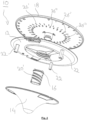
- Air diffuser 1 comprises cover 10 and air diffuser base 30.
- Cover 10 comprises mounting plate 12 provided with three spacers 22.
- Air flow controller 14 is moveably connected to mounting plate 12 by air flow controller adjusting means 16, depicted in figure 1 as screw threads 20, 20', in further connection to handling means 18, depicted in figure 1 as a rotating handling means, like a rotatable disc.
- Cover 10 is further provided with locking mechanism 24 for locking and unlocking the position of air flow controller 14.
- protrusions 26 provided in mounting plate 12 for cooperation with indentations (not shown) provided in handling means 18.
- airflow blocker 28 for directing the air flow.
- Air diffuser base 30 comprises three mounting elements 32 depicted in figure 1 as spacer receiving means 36.
- the spacer receiving means 36 of air diffuser base 30 are configured to clampingly receive spacers 22 of cover 10.
- Air diffuser base 30 is further provided with fixing elements 34 for fixing air diffuser base 30 in an end of an air duct. It is noted that the air flow path 38 is free of any air flow disturbing obstacles.
- the air diffuser base 30 comprises sleeve 40 for receiving base element 42.
- the air diffuser base 30 may further comprise air sealing members 44, 46.
- FIG 2 shows an exploded view of cover 10.
- the indentations 26' provide in handling means 18 are visible.
- the indentations 26' cooperate with the protrusions (not shown) provided in mounting plate 12.
- handling means 18 are provided with resistance elements 26" for cooperation with mounting plate 12.
Landscapes
- Engineering & Computer Science (AREA)
- Chemical & Material Sciences (AREA)
- Combustion & Propulsion (AREA)
- Mechanical Engineering (AREA)
- General Engineering & Computer Science (AREA)
- Air-Flow Control Members (AREA)
- Aeration Devices For Treatment Of Activated Polluted Sludge (AREA)
Applications Claiming Priority (1)
| Application Number | Priority Date | Filing Date | Title |
|---|---|---|---|
| NL2021027A NL2021027B1 (en) | 2018-05-31 | 2018-05-31 | Cover and base for an air diffuser, air diffuser, air diffusing system and method for controlling the air flow of an air diffusing system. |
Publications (3)
| Publication Number | Publication Date |
|---|---|
| EP3575702A1 EP3575702A1 (en) | 2019-12-04 |
| EP3575702B1 true EP3575702B1 (en) | 2024-03-27 |
| EP3575702C0 EP3575702C0 (en) | 2024-03-27 |
Family
ID=64049637
Family Applications (1)
| Application Number | Title | Priority Date | Filing Date |
|---|---|---|---|
| EP19177360.5A Active EP3575702B1 (en) | 2018-05-31 | 2019-05-29 | Air diffuser and air diffusing system |
Country Status (3)
| Country | Link |
|---|---|
| EP (1) | EP3575702B1 (pl) |
| NL (1) | NL2021027B1 (pl) |
| PL (1) | PL3575702T3 (pl) |
Families Citing this family (3)
| Publication number | Priority date | Publication date | Assignee | Title |
|---|---|---|---|---|
| BE1031085B1 (nl) * | 2022-11-30 | 2024-06-24 | Vero Duco | Ventilatieventiel |
| BE1031180B1 (nl) | 2022-12-22 | 2024-07-22 | Renson | Een ventielinrichting voor gebruik in een ventilatiesysteem |
| FR3162834A1 (fr) * | 2024-05-31 | 2025-12-05 | Alexis CHEVALIER | Bouche d'extraction d'air ajustable pour la ventilation d'une pièce, équipée d'un système de montage démontable |
Family Cites Families (5)
| Publication number | Priority date | Publication date | Assignee | Title |
|---|---|---|---|---|
| GB1244725A (en) * | 1967-11-30 | 1971-09-02 | Osma Plastics Ltd | Valves |
| US4800804A (en) * | 1987-08-06 | 1989-01-31 | Tennessee Plastics, Inc. | Variable air flow diffuser |
| NZ247231A (en) * | 1993-03-23 | 1994-10-26 | Holyoake Ind Ltd | Diffuser for air conditioning system; outlet air direction thermostatically controlled |
| DE102011009517A1 (de) * | 2011-01-26 | 2012-07-26 | The Heating Company Bvba | Verstellbares Luftventil |
| KR102203935B1 (ko) * | 2014-01-08 | 2021-01-18 | 삼성전자주식회사 | 토출구 개폐장치 및 이를 포함하는 공기조화기 |
-
2018
- 2018-05-31 NL NL2021027A patent/NL2021027B1/en not_active IP Right Cessation
-
2019
- 2019-05-29 EP EP19177360.5A patent/EP3575702B1/en active Active
- 2019-05-29 PL PL19177360.5T patent/PL3575702T3/pl unknown
Also Published As
| Publication number | Publication date |
|---|---|
| NL2021027B1 (en) | 2019-12-10 |
| EP3575702C0 (en) | 2024-03-27 |
| EP3575702A1 (en) | 2019-12-04 |
| PL3575702T3 (pl) | 2024-08-26 |
Similar Documents
| Publication | Publication Date | Title |
|---|---|---|
| EP3575702B1 (en) | Air diffuser and air diffusing system | |
| US6991534B2 (en) | Adjustable vent | |
| RU2681688C2 (ru) | Вентиляционное устройство с переменной скоростью воздуха | |
| US6527194B1 (en) | Flow control damper | |
| EP2051020B1 (en) | A ventilation device | |
| JPH0820459B2 (ja) | 空気流流速切替え装置 | |
| JP2018173207A (ja) | 可変風量装置 | |
| US3495521A (en) | Manual adjustable control for air valve dampers | |
| KR20090102932A (ko) | 환기덕트의 디퓨저 | |
| KR102235819B1 (ko) | 편류 저감형 디퓨져 | |
| BE1027970B1 (nl) | Klepsamenstel voor een luchtkanaal in of aan een ventilatiesysteem | |
| CN113654228A (zh) | 导风结构、空调器及空调器的控制方法 | |
| US20240255164A1 (en) | An air valve with improved ventilation | |
| US1921457A (en) | Ventilator fitting | |
| US20150369513A1 (en) | Check Valve for Ventilation System | |
| EP3825620A1 (en) | Diffuser for ventilation systems | |
| EP1918656B1 (en) | Ventilation system | |
| KR20100010441U (ko) | 전동 디퓨저 | |
| EP1865270B1 (en) | Device for regulating the air flow rate in a ventilation device | |
| KR200463501Y1 (ko) | 전동 디퓨저 | |
| JP4367245B2 (ja) | 給排気口の施工方法 | |
| JP3775980B2 (ja) | 換気装置 | |
| KR20220051918A (ko) | 자동 조절식 디퓨저 | |
| KR101584539B1 (ko) | 환기 설비용 디퓨저 | |
| US2969009A (en) | Centrifugal take-off and control nozzle |
Legal Events
| Date | Code | Title | Description |
|---|---|---|---|
| PUAI | Public reference made under article 153(3) epc to a published international application that has entered the european phase |
Free format text: ORIGINAL CODE: 0009012 |
|
| STAA | Information on the status of an ep patent application or granted ep patent |
Free format text: STATUS: THE APPLICATION HAS BEEN PUBLISHED |
|
| AK | Designated contracting states |
Kind code of ref document: A1 Designated state(s): AL AT BE BG CH CY CZ DE DK EE ES FI FR GB GR HR HU IE IS IT LI LT LU LV MC MK MT NL NO PL PT RO RS SE SI SK SM TR |
|
| AX | Request for extension of the european patent |
Extension state: BA ME |
|
| STAA | Information on the status of an ep patent application or granted ep patent |
Free format text: STATUS: REQUEST FOR EXAMINATION WAS MADE |
|
| 17P | Request for examination filed |
Effective date: 20200604 |
|
| RBV | Designated contracting states (corrected) |
Designated state(s): AL AT BE BG CH CY CZ DE DK EE ES FI FR GB GR HR HU IE IS IT LI LT LU LV MC MK MT NL NO PL PT RO RS SE SI SK SM TR |
|
| STAA | Information on the status of an ep patent application or granted ep patent |
Free format text: STATUS: EXAMINATION IS IN PROGRESS |
|
| 17Q | First examination report despatched |
Effective date: 20220420 |
|
| P01 | Opt-out of the competence of the unified patent court (upc) registered |
Effective date: 20230527 |
|
| TPAC | Observations filed by third parties |
Free format text: ORIGINAL CODE: EPIDOSNTIPA |
|
| GRAP | Despatch of communication of intention to grant a patent |
Free format text: ORIGINAL CODE: EPIDOSNIGR1 |
|
| STAA | Information on the status of an ep patent application or granted ep patent |
Free format text: STATUS: GRANT OF PATENT IS INTENDED |
|
| INTG | Intention to grant announced |
Effective date: 20240111 |
|
| GRAS | Grant fee paid |
Free format text: ORIGINAL CODE: EPIDOSNIGR3 |
|
| GRAA | (expected) grant |
Free format text: ORIGINAL CODE: 0009210 |
|
| STAA | Information on the status of an ep patent application or granted ep patent |
Free format text: STATUS: THE PATENT HAS BEEN GRANTED |
|
| AK | Designated contracting states |
Kind code of ref document: B1 Designated state(s): AL AT BE BG CH CY CZ DE DK EE ES FI FR GB GR HR HU IE IS IT LI LT LU LV MC MK MT NL NO PL PT RO RS SE SI SK SM TR |
|
| REG | Reference to a national code |
Ref country code: GB Ref legal event code: FG4D |
|
| REG | Reference to a national code |
Ref country code: CH Ref legal event code: EP |
|
| REG | Reference to a national code |
Ref country code: DE Ref legal event code: R096 Ref document number: 602019048887 Country of ref document: DE |
|
| REG | Reference to a national code |
Ref country code: IE Ref legal event code: FG4D |
|
| U01 | Request for unitary effect filed |
Effective date: 20240425 |
|
| P04 | Withdrawal of opt-out of the competence of the unified patent court (upc) registered |
Effective date: 20240514 |
|
| U07 | Unitary effect registered |
Designated state(s): AT BE BG DE DK EE FI FR IT LT LU LV MT NL PT SE SI Effective date: 20240517 |
|
| U20 | Renewal fee for the european patent with unitary effect paid |
Year of fee payment: 6 Effective date: 20240527 |
|
| PG25 | Lapsed in a contracting state [announced via postgrant information from national office to epo] |
Ref country code: GR Free format text: LAPSE BECAUSE OF FAILURE TO SUBMIT A TRANSLATION OF THE DESCRIPTION OR TO PAY THE FEE WITHIN THE PRESCRIBED TIME-LIMIT Effective date: 20240628 |
|
| PG25 | Lapsed in a contracting state [announced via postgrant information from national office to epo] |
Ref country code: HR Free format text: LAPSE BECAUSE OF FAILURE TO SUBMIT A TRANSLATION OF THE DESCRIPTION OR TO PAY THE FEE WITHIN THE PRESCRIBED TIME-LIMIT Effective date: 20240327 Ref country code: RS Free format text: LAPSE BECAUSE OF FAILURE TO SUBMIT A TRANSLATION OF THE DESCRIPTION OR TO PAY THE FEE WITHIN THE PRESCRIBED TIME-LIMIT Effective date: 20240627 |
|
| PG25 | Lapsed in a contracting state [announced via postgrant information from national office to epo] |
Ref country code: RS Free format text: LAPSE BECAUSE OF FAILURE TO SUBMIT A TRANSLATION OF THE DESCRIPTION OR TO PAY THE FEE WITHIN THE PRESCRIBED TIME-LIMIT Effective date: 20240627 Ref country code: NO Free format text: LAPSE BECAUSE OF FAILURE TO SUBMIT A TRANSLATION OF THE DESCRIPTION OR TO PAY THE FEE WITHIN THE PRESCRIBED TIME-LIMIT Effective date: 20240627 Ref country code: HR Free format text: LAPSE BECAUSE OF FAILURE TO SUBMIT A TRANSLATION OF THE DESCRIPTION OR TO PAY THE FEE WITHIN THE PRESCRIBED TIME-LIMIT Effective date: 20240327 Ref country code: GR Free format text: LAPSE BECAUSE OF FAILURE TO SUBMIT A TRANSLATION OF THE DESCRIPTION OR TO PAY THE FEE WITHIN THE PRESCRIBED TIME-LIMIT Effective date: 20240628 |
|
| RAP2 | Party data changed (patent owner data changed or rights of a patent transferred) |
Owner name: VERO DUCO N.V. Owner name: VENTILAIR GROUP NEDERLAND B.V. |
|
| U1H | Name or address of the proprietor changed after the registration of the unitary effect |
Owner name: VERO DUCO N.V.; BE Owner name: VENTILAIR GROUP NEDERLAND B.V.; NL |
|
| PG25 | Lapsed in a contracting state [announced via postgrant information from national office to epo] |
Ref country code: IS Free format text: LAPSE BECAUSE OF FAILURE TO SUBMIT A TRANSLATION OF THE DESCRIPTION OR TO PAY THE FEE WITHIN THE PRESCRIBED TIME-LIMIT Effective date: 20240727 |
|
| PG25 | Lapsed in a contracting state [announced via postgrant information from national office to epo] |
Ref country code: SM Free format text: LAPSE BECAUSE OF FAILURE TO SUBMIT A TRANSLATION OF THE DESCRIPTION OR TO PAY THE FEE WITHIN THE PRESCRIBED TIME-LIMIT Effective date: 20240327 |
|
| PG25 | Lapsed in a contracting state [announced via postgrant information from national office to epo] |
Ref country code: ES Free format text: LAPSE BECAUSE OF FAILURE TO SUBMIT A TRANSLATION OF THE DESCRIPTION OR TO PAY THE FEE WITHIN THE PRESCRIBED TIME-LIMIT Effective date: 20240327 |
|
| PG25 | Lapsed in a contracting state [announced via postgrant information from national office to epo] |
Ref country code: CZ Free format text: LAPSE BECAUSE OF FAILURE TO SUBMIT A TRANSLATION OF THE DESCRIPTION OR TO PAY THE FEE WITHIN THE PRESCRIBED TIME-LIMIT Effective date: 20240327 |
|
| REG | Reference to a national code |
Ref country code: GB Ref legal event code: 732E Free format text: REGISTERED BETWEEN 20240926 AND 20241002 |
|
| PG25 | Lapsed in a contracting state [announced via postgrant information from national office to epo] |
Ref country code: SK Free format text: LAPSE BECAUSE OF FAILURE TO SUBMIT A TRANSLATION OF THE DESCRIPTION OR TO PAY THE FEE WITHIN THE PRESCRIBED TIME-LIMIT Effective date: 20240327 |
|
| PG25 | Lapsed in a contracting state [announced via postgrant information from national office to epo] |
Ref country code: SM Free format text: LAPSE BECAUSE OF FAILURE TO SUBMIT A TRANSLATION OF THE DESCRIPTION OR TO PAY THE FEE WITHIN THE PRESCRIBED TIME-LIMIT Effective date: 20240327 Ref country code: SK Free format text: LAPSE BECAUSE OF FAILURE TO SUBMIT A TRANSLATION OF THE DESCRIPTION OR TO PAY THE FEE WITHIN THE PRESCRIBED TIME-LIMIT Effective date: 20240327 Ref country code: RO Free format text: LAPSE BECAUSE OF FAILURE TO SUBMIT A TRANSLATION OF THE DESCRIPTION OR TO PAY THE FEE WITHIN THE PRESCRIBED TIME-LIMIT Effective date: 20240327 Ref country code: IS Free format text: LAPSE BECAUSE OF FAILURE TO SUBMIT A TRANSLATION OF THE DESCRIPTION OR TO PAY THE FEE WITHIN THE PRESCRIBED TIME-LIMIT Effective date: 20240727 Ref country code: ES Free format text: LAPSE BECAUSE OF FAILURE TO SUBMIT A TRANSLATION OF THE DESCRIPTION OR TO PAY THE FEE WITHIN THE PRESCRIBED TIME-LIMIT Effective date: 20240327 Ref country code: CZ Free format text: LAPSE BECAUSE OF FAILURE TO SUBMIT A TRANSLATION OF THE DESCRIPTION OR TO PAY THE FEE WITHIN THE PRESCRIBED TIME-LIMIT Effective date: 20240327 |
|
| REG | Reference to a national code |
Ref country code: DE Ref legal event code: R097 Ref document number: 602019048887 Country of ref document: DE |
|
| P05 | Withdrawal of opt-out of the competence of the unified patent court (upc) changed |
Free format text: CASE NUMBER: APP_27492/2024 Effective date: 20240517 |
|
| PG25 | Lapsed in a contracting state [announced via postgrant information from national office to epo] |
Ref country code: MC Free format text: LAPSE BECAUSE OF FAILURE TO SUBMIT A TRANSLATION OF THE DESCRIPTION OR TO PAY THE FEE WITHIN THE PRESCRIBED TIME-LIMIT Effective date: 20240327 |
|
| PG25 | Lapsed in a contracting state [announced via postgrant information from national office to epo] |
Ref country code: MC Free format text: LAPSE BECAUSE OF FAILURE TO SUBMIT A TRANSLATION OF THE DESCRIPTION OR TO PAY THE FEE WITHIN THE PRESCRIBED TIME-LIMIT Effective date: 20240327 |
|
| PLBE | No opposition filed within time limit |
Free format text: ORIGINAL CODE: 0009261 |
|
| STAA | Information on the status of an ep patent application or granted ep patent |
Free format text: STATUS: NO OPPOSITION FILED WITHIN TIME LIMIT |
|
| 26N | No opposition filed |
Effective date: 20250103 |
|
| U76 | Licence for the european patent with unitary effect registered |
Designated state(s): AT BE BG DE DK EE FI FR IT LT LU LV MT NL PT SE SI Free format text: SERIAL NUMBER OF LICENSE: 0100 Name of requester: RENSON NV; BE Effective date: 20250124 |
|
| U20 | Renewal fee for the european patent with unitary effect paid |
Year of fee payment: 7 Effective date: 20250528 |
|
| PGFP | Annual fee paid to national office [announced via postgrant information from national office to epo] |
Ref country code: PL Payment date: 20250423 Year of fee payment: 7 |
|
| PGFP | Annual fee paid to national office [announced via postgrant information from national office to epo] |
Ref country code: GB Payment date: 20250527 Year of fee payment: 7 |
|
| PGFP | Annual fee paid to national office [announced via postgrant information from national office to epo] |
Ref country code: CH Payment date: 20250601 Year of fee payment: 7 |
|
| PGFP | Annual fee paid to national office [announced via postgrant information from national office to epo] |
Ref country code: IE Payment date: 20250521 Year of fee payment: 7 |
|
| PG25 | Lapsed in a contracting state [announced via postgrant information from national office to epo] |
Ref country code: CY Free format text: LAPSE BECAUSE OF FAILURE TO SUBMIT A TRANSLATION OF THE DESCRIPTION OR TO PAY THE FEE WITHIN THE PRESCRIBED TIME-LIMIT; INVALID AB INITIO Effective date: 20190529 |
|
| REG | Reference to a national code |
Ref country code: CH Ref legal event code: R18 Free format text: ST27 STATUS EVENT CODE: U-0-0-R10-R18 (AS PROVIDED BY THE NATIONAL OFFICE) Effective date: 20260119 |
|
| PG25 | Lapsed in a contracting state [announced via postgrant information from national office to epo] |
Ref country code: HU Free format text: LAPSE BECAUSE OF FAILURE TO SUBMIT A TRANSLATION OF THE DESCRIPTION OR TO PAY THE FEE WITHIN THE PRESCRIBED TIME-LIMIT; INVALID AB INITIO Effective date: 20190529 |