EP3575673A1 - External light - Google Patents
External light Download PDFInfo
- Publication number
- EP3575673A1 EP3575673A1 EP19172986.2A EP19172986A EP3575673A1 EP 3575673 A1 EP3575673 A1 EP 3575673A1 EP 19172986 A EP19172986 A EP 19172986A EP 3575673 A1 EP3575673 A1 EP 3575673A1
- Authority
- EP
- European Patent Office
- Prior art keywords
- light
- solar panel
- accumulator
- outdoor
- light guide
- Prior art date
- Legal status (The legal status is an assumption and is not a legal conclusion. Google has not performed a legal analysis and makes no representation as to the accuracy of the status listed.)
- Granted
Links
Images

Classifications
-
- F—MECHANICAL ENGINEERING; LIGHTING; HEATING; WEAPONS; BLASTING
- F21—LIGHTING
- F21S—NON-PORTABLE LIGHTING DEVICES; SYSTEMS THEREOF; VEHICLE LIGHTING DEVICES SPECIALLY ADAPTED FOR VEHICLE EXTERIORS
- F21S9/00—Lighting devices with a built-in power supply; Systems employing lighting devices with a built-in power supply
- F21S9/02—Lighting devices with a built-in power supply; Systems employing lighting devices with a built-in power supply the power supply being a battery or accumulator
- F21S9/03—Lighting devices with a built-in power supply; Systems employing lighting devices with a built-in power supply the power supply being a battery or accumulator rechargeable by exposure to light
- F21S9/037—Lighting devices with a built-in power supply; Systems employing lighting devices with a built-in power supply the power supply being a battery or accumulator rechargeable by exposure to light the solar unit and the lighting unit being located within or on the same housing
-
- F—MECHANICAL ENGINEERING; LIGHTING; HEATING; WEAPONS; BLASTING
- F21—LIGHTING
- F21L—LIGHTING DEVICES OR SYSTEMS THEREOF, BEING PORTABLE OR SPECIALLY ADAPTED FOR TRANSPORTATION
- F21L4/00—Electric lighting devices with self-contained electric batteries or cells
- F21L4/08—Electric lighting devices with self-contained electric batteries or cells characterised by means for in situ recharging of the batteries or cells
-
- F—MECHANICAL ENGINEERING; LIGHTING; HEATING; WEAPONS; BLASTING
- F21—LIGHTING
- F21W—INDEXING SCHEME ASSOCIATED WITH SUBCLASSES F21K, F21L, F21S and F21V, RELATING TO USES OR APPLICATIONS OF LIGHTING DEVICES OR SYSTEMS
- F21W2131/00—Use or application of lighting devices or systems not provided for in codes F21W2102/00-F21W2121/00
- F21W2131/10—Outdoor lighting
- F21W2131/103—Outdoor lighting of streets or roads
-
- F—MECHANICAL ENGINEERING; LIGHTING; HEATING; WEAPONS; BLASTING
- F21—LIGHTING
- F21W—INDEXING SCHEME ASSOCIATED WITH SUBCLASSES F21K, F21L, F21S and F21V, RELATING TO USES OR APPLICATIONS OF LIGHTING DEVICES OR SYSTEMS
- F21W2131/00—Use or application of lighting devices or systems not provided for in codes F21W2102/00-F21W2121/00
- F21W2131/10—Outdoor lighting
- F21W2131/109—Outdoor lighting of gardens
-
- F—MECHANICAL ENGINEERING; LIGHTING; HEATING; WEAPONS; BLASTING
- F21—LIGHTING
- F21Y—INDEXING SCHEME ASSOCIATED WITH SUBCLASSES F21K, F21L, F21S and F21V, RELATING TO THE FORM OR THE KIND OF THE LIGHT SOURCES OR OF THE COLOUR OF THE LIGHT EMITTED
- F21Y2103/00—Elongate light sources, e.g. fluorescent tubes
- F21Y2103/10—Elongate light sources, e.g. fluorescent tubes comprising a linear array of point-like light-generating elements
-
- F—MECHANICAL ENGINEERING; LIGHTING; HEATING; WEAPONS; BLASTING
- F21—LIGHTING
- F21Y—INDEXING SCHEME ASSOCIATED WITH SUBCLASSES F21K, F21L, F21S and F21V, RELATING TO THE FORM OR THE KIND OF THE LIGHT SOURCES OR OF THE COLOUR OF THE LIGHT EMITTED
- F21Y2115/00—Light-generating elements of semiconductor light sources
- F21Y2115/10—Light-emitting diodes [LED]
-
- G—PHYSICS
- G02—OPTICS
- G02B—OPTICAL ELEMENTS, SYSTEMS OR APPARATUS
- G02B6/00—Light guides; Structural details of arrangements comprising light guides and other optical elements, e.g. couplings
- G02B6/0001—Light guides; Structural details of arrangements comprising light guides and other optical elements, e.g. couplings specially adapted for lighting devices or systems
- G02B6/0011—Light guides; Structural details of arrangements comprising light guides and other optical elements, e.g. couplings specially adapted for lighting devices or systems the light guides being planar or of plate-like form
- G02B6/0081—Mechanical or electrical aspects of the light guide and light source in the lighting device peculiar to the adaptation to planar light guides, e.g. concerning packaging
- G02B6/0095—Light guides as housings, housing portions, shelves, doors, tiles, windows, or the like
-
- Y—GENERAL TAGGING OF NEW TECHNOLOGICAL DEVELOPMENTS; GENERAL TAGGING OF CROSS-SECTIONAL TECHNOLOGIES SPANNING OVER SEVERAL SECTIONS OF THE IPC; TECHNICAL SUBJECTS COVERED BY FORMER USPC CROSS-REFERENCE ART COLLECTIONS [XRACs] AND DIGESTS
- Y02—TECHNOLOGIES OR APPLICATIONS FOR MITIGATION OR ADAPTATION AGAINST CLIMATE CHANGE
- Y02B—CLIMATE CHANGE MITIGATION TECHNOLOGIES RELATED TO BUILDINGS, e.g. HOUSING, HOUSE APPLIANCES OR RELATED END-USER APPLICATIONS
- Y02B20/00—Energy efficient lighting technologies, e.g. halogen lamps or gas discharge lamps
- Y02B20/72—Energy efficient lighting technologies, e.g. halogen lamps or gas discharge lamps in street lighting
Definitions
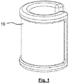
- the invention relates to an outdoor lamp, in particular garden or camping lamp with an accumulator, a solar panel and a light source, which emits light via a light guide to an optical light-emitting element.
- Solar lamps of the type mentioned have the advantage that they can be operated independently of a mains voltage and cost, because the energy required for lighting is obtained solely from the sunlight.
- the solar panel used is electrically connected to a rechargeable accumulator so that the electrical energy gained through the daylight can be stored. Either a switch or sensors, the accumulator with a light source, usually a light emitting diode (LED) is connected, the energy consumption for operation is low.
- Solar lamps can be used as garden lights, path lights or street lights.
- the solar lamp housing consists of a cube with six wall surfaces, which is arranged on its tip standing on a fixture and has solar modules on at least two of its upper surfaces. By this measure it is achieved that the planar solar panel does not always have to be aligned with the position of the sun, since the upwardly directed cube surfaces already cover several directions of irradiation.
- the downside cube faces are used as light emitting surfaces.
- a solar power system in which the solar cells are applied to a curved outer surface of a receiving body, which is designed as a hemispherical shell.
- the usual electrical components are arranged on a circular disc.
- a support structure forms a hemisphere, which is outwardly equipped with various solar cells, which are surrounded by a weatherproof transparent protective cover.
- the interior of the support structure is followed by a heat-cold insulation layer, followed by a layer of battery formed of malleable, lightweight lithium batteries is formed.
- the inside closure forms a protective shell.
- the entire hollow structure is supported by a rigid base plate with a recess for receiving a mast sleeve. On this base plate several LEDs are arranged.
- the DE 10 2015 224 592 B4 describes a garden lamp with a light source powered by a solar panel, a rod of a first self-luminous plastic and a rod connected to the light element of a second self-luminous plastic, wherein the light source is arranged on a first end side of the rod that emitted from the light source Light is coupled into the rod and this penetrates.
- the rod is connected to the luminous element in such a way that the light coupled into the rod is introduced into the luminous element, so that both the rod and the luminous element radiate over their surface the light emitted by the luminous plastic and emitted by the light source at least temporarily in parallel ,
- a rod is used as a light guide, which is also equipped with fluorescent additives.
- the disadvantage of this arrangement is that the solar panel and the optical light-emitting element are separated from each other, so that there is a large volume of construction.
- the light guide serving as a rod also does not work lossless, so that the effective radiation power is relatively low.
- a solar lamp with a housing, a solar cell and an accumulator and a light source that consists of a light emitting diode, a light guide and a crystal, wherein the light generated by the light diode is indirectly passed through the light guide to the crystal and can be emitted by this crystal ,
- the outdoor lamp according to claim 1 which is characterized in that on the outside of a carrier body with a convex lateral surface, the solar panel is attached, which is covered by serving as a light guide and optical light-emitting element transparent coating layer having at least one end face, in which irradiates at least one LED light fed from the accumulator or the solar panel.
- the battery formed as a film, in particular Li-accumulator is disposed between the carrier shell and the solar panel.
- the carrier body is tubular and has a longitudinal slot in which at least one LED or a plurality of LEDs are arranged on a strip.
- a longitudinally slotted cylindrical tube is used as the carrier body, LED strips can be arranged on each of the end faces of this slot, which emit light on both sides into the transparent layer designed as a light guide and an optical luminous element.
- cylinder tubes have the advantage, in contrast to flat or hemispherical curved solar panels, that the sunlight is utilized from any direction for power generation.
- a light guide is understood to mean a glass body which, according to the law of total reflection, transports the light to the exit end. In this way, the light emitted by the LED is transported around the cylinder and steered so that a uniform light emission takes place on all sides.
- a light transparent body e.g.
- the entire outer cylinder jacket is utilized as a support surface for the parts extending all around, such as the solar panel, the accumulator and the light guide / luminous element.
- Such an outdoor light can also be string on a string or a rope, so that in particular several such outdoor lights can be easily installed as temporary path lights or festive lighting. Such outdoor lights, even as fairy lights are low maintenance, robust and relatively shockproof.
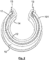
- the outdoor light consists essentially of a support 14 which forms the inside of a longitudinal slot having a piece of pipe.
- a support 14 which forms the inside of a longitudinal slot having a piece of pipe.
- At the open end of the longitudinal slot of the carrier 14 is formed in cross-section U-shaped and comprises or engages over the outer wall, which is formed by a light guide 10, which is transparent to incident from the outside irradiation.
- a solar panel 11 and an accumulator 12 are arranged between this light guide 10 with an end face 101 at its upper end and the carrier 14.
- the accumulator which is fed by the solar panel 11, supplies light emitting diodes on an LED strip 13, which is arranged as a strip on a longitudinal end face of the light guide 10.
- the outdoor light can be used as part of a path lighting, in a lined-up form as a locally arbitrarily suspended lighting or as a position or orientation light.
Landscapes
- Engineering & Computer Science (AREA)
- General Engineering & Computer Science (AREA)
- Life Sciences & Earth Sciences (AREA)
- Sustainable Development (AREA)
- Non-Portable Lighting Devices Or Systems Thereof (AREA)
Abstract
Die Erfindung betrifft eine Außenleuchte, insbesondere Garten- oder Campingleuchte mit einem Akkumulator (12), einem Solarpaneel (11) und einer Lichtquelle, die über einen Lichtleiter (10) Licht an ein optisches Leuchtelement abgibt. Um eine kompakte Außenleuchte mit größtmöglicher Effizienz zu schaffen, wird erfindungsgemäß vorgeschlagen, dass an der Außenseite eines Trägerkörpers (14) mit einer konvexen Mantelfläche das Solarpaneel (11) befestigt ist, das von einer als Lichtleiter (10) und optisches Leuchtelement dienenden transparenten Hüllschicht mit mindestens einer Stirnfläche (101) abgedeckt ist, in die mindestens eine aus dem Akkumulator (12) und dem Solarpaneel (11) gespeiste LED Licht einstrahlt.

Description
Die Erfindung betrifft eine Außenleuchte, insbesondere Garten- oder Campingleuchte mit einem Akkumulator, einem Solarpaneel und einer Lichtquelle, die über einen Lichtleiter Licht an ein optisches Leuchtelement abgibt.The invention relates to an outdoor lamp, in particular garden or camping lamp with an accumulator, a solar panel and a light source, which emits light via a light guide to an optical light-emitting element.
Solarlampen der genannten Art besitzen den Vorteil, dass sie unabhängig von einer Netzspannung und kostengünstig betrieben werden können, weil die zur Beleuchtung benötigte Energie allein aus dem Sonnenlicht gewonnen wird. Das verwendete Solarpaneel ist mit einem wiederaufladbaren Akkumulator elektrisch verbunden, so dass die über das Tageslicht gewonnene elektrische Energie gespeichert werden kann. Entweder über einen Schalter oder Sensoren wird der Akkumulator mit einer Lichtquelle, zumeist einer Leuchtdiode (LED) verbunden, deren Energiebedarf zum Betrieb gering ist. Solarlampen können als Gartenleuchten, Wegleuchten oder Straßenleuchten verwendet werden. Zur Optimierung der Energiegewinnung wird in der
In der
Die
In der
Es ist Aufgabe der vorliegenden Erfindung, die eingangs genannte solarbetriebene Außenleuchte im Hinblick auf eine kompakte Bauweise und größtmögliche Effizienz zu optimieren.It is an object of the present invention to optimize the above-mentioned solar powered outdoor lamp in terms of a compact design and maximum efficiency.
Diese Aufgabe wir durch die Außenleuchte nach Anspruch 1 gelöst, die dadurch gekennzeichnet ist, dass an der Außenseite eines Trägerkörpers mit einer konvexen Mantelfläche das Solarpaneel befestigt ist, das von einer als Lichtleiter und optisches Leuchtelement dienenden transparenten Hüllschicht mit mindestens einer Stirnfläche abgedeckt ist, in die mindestens eine aus dem Akkumulator oder dem Solarpaneel gespeiste LED Licht einstrahlt. Vorzugsweise ist zwischen dem Trägermantel und dem Solarpaneel der als Folie ausgebildete Akkumulator, insbesondere Li-Akkumulator angeordnet.This object is achieved by the outdoor lamp according to claim 1, which is characterized in that on the outside of a carrier body with a convex lateral surface, the solar panel is attached, which is covered by serving as a light guide and optical light-emitting element transparent coating layer having at least one end face, in which irradiates at least one LED light fed from the accumulator or the solar panel. Preferably, the battery formed as a film, in particular Li-accumulator is disposed between the carrier shell and the solar panel.
Eine weiterhin optimierte Bauform ergibt sich, indem der Trägerkörper rohrförmig ausgebildet ist und einen Längsschlitz aufweist, in dem mindestens eine LED oder mehrere LED auf einem Streifen angeordnet sind.A further optimized design results in that the carrier body is tubular and has a longitudinal slot in which at least one LED or a plurality of LEDs are arranged on a strip.
Verwendet man als Trägerkörper ein längs geschlitztes Zylinderrohr, können jeweils an den Stirnflächen dieses Schlitzes LED-Streifen angeordnet werden, die zu beiden Seiten Licht in die als Lichtleiter und optisches Leuchtelement ausgestaltete transparente Schicht einstrahlen. Sollte Zylinderrohre haben im Gegensatz zu ebenen oder halbkugelförmig gewölbten Solarpaneelen den Vorteil, dass das Sonnenlicht aus beliebigen Richtungen zur Stromerzeugung verwertet wird. Unter einem Lichtleiter wird ein Glaskörper verstanden, der nach dem Gesetz der Totalreflexion das Licht an das Austrittsende transportiert. Auf diese Weise wird das über die LED eingestrahlte Licht ringsum des Zylinders transportiert und so gelenkt, dass nach allen Seiten eine gleichmäßige Lichtabstrahlung erfolgt. Ein solcher lichttransparenter Körper, der z.B. aus Glas oder Kunststoff bestehen kann, dient gleichzeitig als Schutzhülle für das Solarpaneel und den folienhaften Akkumulator. Erfindungsgemäß wird der gesamte Außenzylindermantel als Stützfläche für die sich ringsum vollflächig erstreckenden Teile wie Solarpaneel, Akkumulator und Lichtleiter/Leuchtelement ausgenutzt.If a longitudinally slotted cylindrical tube is used as the carrier body, LED strips can be arranged on each of the end faces of this slot, which emit light on both sides into the transparent layer designed as a light guide and an optical luminous element. If cylinder tubes have the advantage, in contrast to flat or hemispherical curved solar panels, that the sunlight is utilized from any direction for power generation. A light guide is understood to mean a glass body which, according to the law of total reflection, transports the light to the exit end. In this way, the light emitted by the LED is transported around the cylinder and steered so that a uniform light emission takes place on all sides. Such a light transparent body, e.g. made of glass or plastic, also serves as a protective cover for the solar panel and the foil-like accumulator. According to the invention, the entire outer cylinder jacket is utilized as a support surface for the parts extending all around, such as the solar panel, the accumulator and the light guide / luminous element.
Durch diese Anordnung wird sowohl eine kompakte Bauweise als auch ein Strahlungsverlust wirkungsvoll vermieden, da die Wege, welche das Licht zurücklegen muss, geringstmöglich sind. Eine solche Außenleuchte lässt sich auch auf eine Schnur oder ein Seil auffädeln, so dass insbesondere mehrere solcher Außenleuchten als temporäre Wegleuchten oder Festbeleuchtung leicht installiert werden können. Solche Außenleuchten, auch als Lichterketten sind wartungsarm, robust und relativ stoßfest.By this arrangement, both a compact design and a radiation loss is effectively avoided, since the paths that must cover the light, are as small as possible. Such an outdoor light can also be string on a string or a rope, so that in particular several such outdoor lights can be easily installed as temporary path lights or festive lighting. Such outdoor lights, even as fairy lights are low maintenance, robust and relatively shockproof.
Die erfindungsgemäße Außenleuchte wird im Folgenden anhand der
- Fig. 1
- eine perspektivische Ansicht einer Außenleuchte,
- Fig. 2
- eine perspektivische Querschnittsansicht der Leuchte nach
Fig. 1 und - Fig. 3
- eine teilgeschnittene perspektivische Ansicht der Leuchte nach
Fig. 1 .
- Fig. 1
- a perspective view of an outdoor lamp,
- Fig. 2
- a perspective cross-sectional view of the lamp according to
Fig. 1 and - Fig. 3
- a partially cutaway perspective view of the light after
Fig. 1 ,
Die Außenleuchte besteht im Wesentlichen aus einem Träger 14, der die Innenseite eines einen Längsschlitz aufweisenden Rohrstückes bildet. Am offenen Ende des Längsschlitzes ist der Träger 14 im Querschnitt U-förmig ausgebildet und umfasst bzw. übergreift die Außenwandung, die durch einen Lichtleiter 10 gebildet wird, die für von außen auftreffende Bestrahlung lichtdurchlässig ist. Zwischen diesem Lichtleiter 10 mit einer Stirnfläche 101 an deren oberem Ende und dem Träger 14 sind ein Solarpaneel 11 sowie ein Akkumulator 12 angeordnet. Der Akkumulator, der von dem Solarpaneel 11 gespeist wird, versorgt Leuchtdioden auf einer LED-Leiste 13, die als Streifen an einer Längs-Stirnseite des Lichtleiters 10 angeordnet ist. Von dieser LED-Leiste 13 eingestrahltes Licht wird aufgrund des konstruktiven Aufbaus im Lichtleiter so abgelenkt, dass es von geringen Verlusten abgesehen an der Stirnfläche 101 des Lichtleiters austritt, so dass die Außenleuchte als Leuchtmittel benutzt werden kann. Die Außenleuchte kann als Teil einer Wegbeleuchtung, in aufgereihter Form als lokal beliebig aufhängbare Platzbeleuchtung oder auch als Positions- oder Orientierungsleuchte verwendet werden.The outdoor light consists essentially of a
Claims (5)
dadurch gekennzeichnet, dass
an der Außenseite eines Trägerkörpers (14) mit einer konvexen Mantelfläche das Solarpaneel (11) befestigt ist, das von einer als Lichtleiter (10) und optisches Leuchtelement dienenden transparenten Hüllschicht mit mindestens einer Stirnfläche abgedeckt ist, in die mindestens eine aus dem Akkumulator (12) und dem Solarpaneel (11) gespeiste LED Licht einstrahlt.Outdoor light, in particular garden or campsite light, with an accumulator (12), a solar panel (11) and a light source, which emits light via a light guide (10) to an optical light-emitting element,
characterized in that
on the outside of a carrier body (14) with a convex lateral surface, the solar panel (11) is fixed, which is covered by a serving as a light guide (10) and optical light-emitting transparent cladding layer having at least one end face into which at least one of the accumulator (12 ) and the solar panel (11) fed LED light irradiates.
Applications Claiming Priority (1)
| Application Number | Priority Date | Filing Date | Title |
|---|---|---|---|
| DE102018112784.7A DE102018112784A1 (en) | 2018-05-29 | 2018-05-29 | outdoor light |
Publications (2)
| Publication Number | Publication Date |
|---|---|
| EP3575673A1 true EP3575673A1 (en) | 2019-12-04 |
| EP3575673B1 EP3575673B1 (en) | 2020-12-16 |
Family
ID=66554131
Family Applications (1)
| Application Number | Title | Priority Date | Filing Date |
|---|---|---|---|
| EP19172986.2A Active EP3575673B1 (en) | 2018-05-29 | 2019-05-07 | External light |
Country Status (2)
| Country | Link |
|---|---|
| EP (1) | EP3575673B1 (en) |
| DE (1) | DE102018112784A1 (en) |
Citations (10)
| Publication number | Priority date | Publication date | Assignee | Title |
|---|---|---|---|---|
| WO1997040535A2 (en) * | 1996-04-23 | 1997-10-30 | Ralf Stobbe | System for recovering energy radiated by electrodeless light sources |
| EP1230513A1 (en) | 1999-11-12 | 2002-08-14 | Wolfgang Wismeth | Solar lamp for open-air use |
| DE20307319U1 (en) | 2003-05-09 | 2003-07-10 | Oliver Richter GmbH & Co. KG, 20355 Hamburg | Solar lamp e.g. for garden lighting, uses light generated by LED diode for radiation into ambience via crystal |
| EP1346672A1 (en) * | 2002-03-20 | 2003-09-24 | Dominic Wirtz | Device used to illuminate objects and rooms |
| DE10336543B4 (en) | 2003-08-05 | 2006-03-23 | Russler, Theodor | Solar power system |
| US20090251892A1 (en) * | 2008-04-08 | 2009-10-08 | Kiran Hatti | Lighting Apparatus |
| DE202012006496U1 (en) * | 2012-07-04 | 2012-08-06 | P.H. Wert-Design E.K. | lamp |
| GB2532713A (en) * | 2014-10-27 | 2016-06-01 | Zeta Specialist Lighting Ltd | Lighting assembly |
| DE102015015970A1 (en) * | 2015-12-01 | 2017-06-01 | Nikolai Koehler | Device system of a solar lamp with a housing of a foil-like photovoltaic module |
| DE102015224592B4 (en) | 2015-12-08 | 2017-11-02 | Krinner Innovation Gmbh | GARDEN LIGHT |
Family Cites Families (1)
| Publication number | Priority date | Publication date | Assignee | Title |
|---|---|---|---|---|
| DE20120155U1 (en) * | 2001-12-12 | 2003-01-30 | Doda, Prince Joycen, 33428 Marienfeld | Street light or lamp comprises a shaft in the form of an elongate thin-walled hollow profile whose outer surfaces carry solar cells serving for production of electric current |
-
2018
- 2018-05-29 DE DE102018112784.7A patent/DE102018112784A1/en not_active Withdrawn
-
2019
- 2019-05-07 EP EP19172986.2A patent/EP3575673B1/en active Active
Patent Citations (10)
| Publication number | Priority date | Publication date | Assignee | Title |
|---|---|---|---|---|
| WO1997040535A2 (en) * | 1996-04-23 | 1997-10-30 | Ralf Stobbe | System for recovering energy radiated by electrodeless light sources |
| EP1230513A1 (en) | 1999-11-12 | 2002-08-14 | Wolfgang Wismeth | Solar lamp for open-air use |
| EP1346672A1 (en) * | 2002-03-20 | 2003-09-24 | Dominic Wirtz | Device used to illuminate objects and rooms |
| DE20307319U1 (en) | 2003-05-09 | 2003-07-10 | Oliver Richter GmbH & Co. KG, 20355 Hamburg | Solar lamp e.g. for garden lighting, uses light generated by LED diode for radiation into ambience via crystal |
| DE10336543B4 (en) | 2003-08-05 | 2006-03-23 | Russler, Theodor | Solar power system |
| US20090251892A1 (en) * | 2008-04-08 | 2009-10-08 | Kiran Hatti | Lighting Apparatus |
| DE202012006496U1 (en) * | 2012-07-04 | 2012-08-06 | P.H. Wert-Design E.K. | lamp |
| GB2532713A (en) * | 2014-10-27 | 2016-06-01 | Zeta Specialist Lighting Ltd | Lighting assembly |
| DE102015015970A1 (en) * | 2015-12-01 | 2017-06-01 | Nikolai Koehler | Device system of a solar lamp with a housing of a foil-like photovoltaic module |
| DE102015224592B4 (en) | 2015-12-08 | 2017-11-02 | Krinner Innovation Gmbh | GARDEN LIGHT |
Also Published As
| Publication number | Publication date |
|---|---|
| DE102018112784A1 (en) | 2019-12-05 |
| EP3575673B1 (en) | 2020-12-16 |
Similar Documents
| Publication | Publication Date | Title |
|---|---|---|
| DE102009035516B4 (en) | Lighting device with LEDs | |
| DE102009032544B4 (en) | Lighting device with solar cell | |
| DE29919948U1 (en) | Solar lamp for outdoor use | |
| WO2007115737A1 (en) | Lighting arrangement | |
| EP2850705B1 (en) | Support rail for holding and supplying power to a plurality of lighting modules, and light strip system with such a support rail | |
| EP2743564B1 (en) | Lighting device and illumination arrangement for lighting the interior of a tower or tunnel | |
| DE20214879U1 (en) | lighting device | |
| EP1852649A1 (en) | Solar powered mast luminaire | |
| DE102009058310B4 (en) | LED luminaire insert with light control element | |
| DE102012008979A1 (en) | Lighting system for flagpoles, poles, poles, pennants, flags, flags and banners | |
| DE10036998A1 (en) | Solar powered outdoor lighting unit on pole, includes LED array in which diode leads are connected directly to metallic casing supporting array | |
| EP3575673B1 (en) | External light | |
| DE202011000903U1 (en) | Solar system with artificial light source | |
| DE202018102989U1 (en) | outdoor light | |
| DE102013110857A1 (en) | Beacon for firing a wind turbine, in particular a tower of a wind turbine | |
| DE202012006496U1 (en) | lamp | |
| DE202010004479U1 (en) | LED Fluorescent Replacement | |
| DE102018113484B3 (en) | DEVICE FOR CONVERTING SUNLIGHT IN ELECTRICAL ENERGY | |
| EP1103757A2 (en) | Lighting system for rooms | |
| DE202007006815U1 (en) | module | |
| EP3627045A1 (en) | Lighting insert module | |
| DE20313634U1 (en) | Electrical battery powered lighting unit has uses a flexible electroluminescent foil that is pulled out of housing to create an illumination panel | |
| AT16273U1 (en) | Lamp with solar cells | |
| DE20300283U1 (en) | light module | |
| CH719039B1 (en) | Solar powered warning light, circuit for controlling and method for operating the warning light |
Legal Events
| Date | Code | Title | Description |
|---|---|---|---|
| PUAI | Public reference made under article 153(3) epc to a published international application that has entered the european phase |
Free format text: ORIGINAL CODE: 0009012 |
|
| STAA | Information on the status of an ep patent application or granted ep patent |
Free format text: STATUS: THE APPLICATION HAS BEEN PUBLISHED |
|
| STAA | Information on the status of an ep patent application or granted ep patent |
Free format text: STATUS: REQUEST FOR EXAMINATION WAS MADE |
|
| AK | Designated contracting states |
Kind code of ref document: A1 Designated state(s): AL AT BE BG CH CY CZ DE DK EE ES FI FR GB GR HR HU IE IS IT LI LT LU LV MC MK MT NL NO PL PT RO RS SE SI SK SM TR |
|
| AX | Request for extension of the european patent |
Extension state: BA ME |
|
| 17P | Request for examination filed |
Effective date: 20191107 |
|
| RBV | Designated contracting states (corrected) |
Designated state(s): AL AT BE BG CH CY CZ DE DK EE ES FI FR GB GR HR HU IE IS IT LI LT LU LV MC MK MT NL NO PL PT RO RS SE SI SK SM TR |
|
| RIC1 | Information provided on ipc code assigned before grant |
Ipc: F21S 9/03 20060101AFI20200724BHEP Ipc: F21Y 103/10 20160101ALN20200724BHEP Ipc: F21W 131/109 20060101ALN20200724BHEP Ipc: F21V 8/00 20060101ALN20200724BHEP Ipc: F21Y 115/10 20160101ALN20200724BHEP Ipc: F21L 4/08 20060101ALI20200724BHEP Ipc: F21W 131/103 20060101ALN20200724BHEP |
|
| GRAP | Despatch of communication of intention to grant a patent |
Free format text: ORIGINAL CODE: EPIDOSNIGR1 |
|
| STAA | Information on the status of an ep patent application or granted ep patent |
Free format text: STATUS: GRANT OF PATENT IS INTENDED |
|
| INTG | Intention to grant announced |
Effective date: 20200908 |
|
| GRAS | Grant fee paid |
Free format text: ORIGINAL CODE: EPIDOSNIGR3 |
|
| GRAA | (expected) grant |
Free format text: ORIGINAL CODE: 0009210 |
|
| STAA | Information on the status of an ep patent application or granted ep patent |
Free format text: STATUS: THE PATENT HAS BEEN GRANTED |
|
| AK | Designated contracting states |
Kind code of ref document: B1 Designated state(s): AL AT BE BG CH CY CZ DE DK EE ES FI FR GB GR HR HU IE IS IT LI LT LU LV MC MK MT NL NO PL PT RO RS SE SI SK SM TR |
|
| REG | Reference to a national code |
Ref country code: GB Ref legal event code: FG4D Free format text: NOT ENGLISH |
|
| REG | Reference to a national code |
Ref country code: DE Ref legal event code: R096 Ref document number: 502019000533 Country of ref document: DE |
|
| REG | Reference to a national code |
Ref country code: IE Ref legal event code: FG4D Free format text: LANGUAGE OF EP DOCUMENT: GERMAN |
|
| REG | Reference to a national code |
Ref country code: AT Ref legal event code: REF Ref document number: 1345926 Country of ref document: AT Kind code of ref document: T Effective date: 20210115 |
|
| PG25 | Lapsed in a contracting state [announced via postgrant information from national office to epo] |
Ref country code: RS Free format text: LAPSE BECAUSE OF FAILURE TO SUBMIT A TRANSLATION OF THE DESCRIPTION OR TO PAY THE FEE WITHIN THE PRESCRIBED TIME-LIMIT Effective date: 20201216 Ref country code: FI Free format text: LAPSE BECAUSE OF FAILURE TO SUBMIT A TRANSLATION OF THE DESCRIPTION OR TO PAY THE FEE WITHIN THE PRESCRIBED TIME-LIMIT Effective date: 20201216 Ref country code: GR Free format text: LAPSE BECAUSE OF FAILURE TO SUBMIT A TRANSLATION OF THE DESCRIPTION OR TO PAY THE FEE WITHIN THE PRESCRIBED TIME-LIMIT Effective date: 20210317 Ref country code: NO Free format text: LAPSE BECAUSE OF FAILURE TO SUBMIT A TRANSLATION OF THE DESCRIPTION OR TO PAY THE FEE WITHIN THE PRESCRIBED TIME-LIMIT Effective date: 20210316 |
|
| REG | Reference to a national code |
Ref country code: NL Ref legal event code: MP Effective date: 20201216 |
|
| PG25 | Lapsed in a contracting state [announced via postgrant information from national office to epo] |
Ref country code: BG Free format text: LAPSE BECAUSE OF FAILURE TO SUBMIT A TRANSLATION OF THE DESCRIPTION OR TO PAY THE FEE WITHIN THE PRESCRIBED TIME-LIMIT Effective date: 20210316 Ref country code: SE Free format text: LAPSE BECAUSE OF FAILURE TO SUBMIT A TRANSLATION OF THE DESCRIPTION OR TO PAY THE FEE WITHIN THE PRESCRIBED TIME-LIMIT Effective date: 20201216 Ref country code: LV Free format text: LAPSE BECAUSE OF FAILURE TO SUBMIT A TRANSLATION OF THE DESCRIPTION OR TO PAY THE FEE WITHIN THE PRESCRIBED TIME-LIMIT Effective date: 20201216 |
|
| PG25 | Lapsed in a contracting state [announced via postgrant information from national office to epo] |
Ref country code: HR Free format text: LAPSE BECAUSE OF FAILURE TO SUBMIT A TRANSLATION OF THE DESCRIPTION OR TO PAY THE FEE WITHIN THE PRESCRIBED TIME-LIMIT Effective date: 20201216 Ref country code: NL Free format text: LAPSE BECAUSE OF FAILURE TO SUBMIT A TRANSLATION OF THE DESCRIPTION OR TO PAY THE FEE WITHIN THE PRESCRIBED TIME-LIMIT Effective date: 20201216 |
|
| REG | Reference to a national code |
Ref country code: LT Ref legal event code: MG9D |
|
| PG25 | Lapsed in a contracting state [announced via postgrant information from national office to epo] |
Ref country code: EE Free format text: LAPSE BECAUSE OF FAILURE TO SUBMIT A TRANSLATION OF THE DESCRIPTION OR TO PAY THE FEE WITHIN THE PRESCRIBED TIME-LIMIT Effective date: 20201216 Ref country code: SM Free format text: LAPSE BECAUSE OF FAILURE TO SUBMIT A TRANSLATION OF THE DESCRIPTION OR TO PAY THE FEE WITHIN THE PRESCRIBED TIME-LIMIT Effective date: 20201216 Ref country code: SK Free format text: LAPSE BECAUSE OF FAILURE TO SUBMIT A TRANSLATION OF THE DESCRIPTION OR TO PAY THE FEE WITHIN THE PRESCRIBED TIME-LIMIT Effective date: 20201216 Ref country code: CZ Free format text: LAPSE BECAUSE OF FAILURE TO SUBMIT A TRANSLATION OF THE DESCRIPTION OR TO PAY THE FEE WITHIN THE PRESCRIBED TIME-LIMIT Effective date: 20201216 Ref country code: LT Free format text: LAPSE BECAUSE OF FAILURE TO SUBMIT A TRANSLATION OF THE DESCRIPTION OR TO PAY THE FEE WITHIN THE PRESCRIBED TIME-LIMIT Effective date: 20201216 Ref country code: RO Free format text: LAPSE BECAUSE OF FAILURE TO SUBMIT A TRANSLATION OF THE DESCRIPTION OR TO PAY THE FEE WITHIN THE PRESCRIBED TIME-LIMIT Effective date: 20201216 Ref country code: PT Free format text: LAPSE BECAUSE OF FAILURE TO SUBMIT A TRANSLATION OF THE DESCRIPTION OR TO PAY THE FEE WITHIN THE PRESCRIBED TIME-LIMIT Effective date: 20210416 |
|
| PG25 | Lapsed in a contracting state [announced via postgrant information from national office to epo] |
Ref country code: PL Free format text: LAPSE BECAUSE OF FAILURE TO SUBMIT A TRANSLATION OF THE DESCRIPTION OR TO PAY THE FEE WITHIN THE PRESCRIBED TIME-LIMIT Effective date: 20201216 |
|
| REG | Reference to a national code |
Ref country code: DE Ref legal event code: R097 Ref document number: 502019000533 Country of ref document: DE |
|
| PG25 | Lapsed in a contracting state [announced via postgrant information from national office to epo] |
Ref country code: IS Free format text: LAPSE BECAUSE OF FAILURE TO SUBMIT A TRANSLATION OF THE DESCRIPTION OR TO PAY THE FEE WITHIN THE PRESCRIBED TIME-LIMIT Effective date: 20210416 |
|
| PLBE | No opposition filed within time limit |
Free format text: ORIGINAL CODE: 0009261 |
|
| STAA | Information on the status of an ep patent application or granted ep patent |
Free format text: STATUS: NO OPPOSITION FILED WITHIN TIME LIMIT |
|
| PG25 | Lapsed in a contracting state [announced via postgrant information from national office to epo] |
Ref country code: AL Free format text: LAPSE BECAUSE OF FAILURE TO SUBMIT A TRANSLATION OF THE DESCRIPTION OR TO PAY THE FEE WITHIN THE PRESCRIBED TIME-LIMIT Effective date: 20201216 Ref country code: IT Free format text: LAPSE BECAUSE OF FAILURE TO SUBMIT A TRANSLATION OF THE DESCRIPTION OR TO PAY THE FEE WITHIN THE PRESCRIBED TIME-LIMIT Effective date: 20201216 |
|
| 26N | No opposition filed |
Effective date: 20210917 |
|
| PG25 | Lapsed in a contracting state [announced via postgrant information from national office to epo] |
Ref country code: DK Free format text: LAPSE BECAUSE OF FAILURE TO SUBMIT A TRANSLATION OF THE DESCRIPTION OR TO PAY THE FEE WITHIN THE PRESCRIBED TIME-LIMIT Effective date: 20201216 |
|
| PG25 | Lapsed in a contracting state [announced via postgrant information from national office to epo] |
Ref country code: ES Free format text: LAPSE BECAUSE OF FAILURE TO SUBMIT A TRANSLATION OF THE DESCRIPTION OR TO PAY THE FEE WITHIN THE PRESCRIBED TIME-LIMIT Effective date: 20201216 Ref country code: MC Free format text: LAPSE BECAUSE OF FAILURE TO SUBMIT A TRANSLATION OF THE DESCRIPTION OR TO PAY THE FEE WITHIN THE PRESCRIBED TIME-LIMIT Effective date: 20201216 Ref country code: LU Free format text: LAPSE BECAUSE OF NON-PAYMENT OF DUE FEES Effective date: 20210507 |
|
| REG | Reference to a national code |
Ref country code: BE Ref legal event code: MM Effective date: 20210531 |
|
| PG25 | Lapsed in a contracting state [announced via postgrant information from national office to epo] |
Ref country code: SI Free format text: LAPSE BECAUSE OF FAILURE TO SUBMIT A TRANSLATION OF THE DESCRIPTION OR TO PAY THE FEE WITHIN THE PRESCRIBED TIME-LIMIT Effective date: 20201216 |
|
| PG25 | Lapsed in a contracting state [announced via postgrant information from national office to epo] |
Ref country code: IE Free format text: LAPSE BECAUSE OF NON-PAYMENT OF DUE FEES Effective date: 20210507 |
|
| PG25 | Lapsed in a contracting state [announced via postgrant information from national office to epo] |
Ref country code: IS Free format text: LAPSE BECAUSE OF FAILURE TO SUBMIT A TRANSLATION OF THE DESCRIPTION OR TO PAY THE FEE WITHIN THE PRESCRIBED TIME-LIMIT Effective date: 20210416 Ref country code: FR Free format text: LAPSE BECAUSE OF NON-PAYMENT OF DUE FEES Effective date: 20210531 |
|
| PG25 | Lapsed in a contracting state [announced via postgrant information from national office to epo] |
Ref country code: BE Free format text: LAPSE BECAUSE OF NON-PAYMENT OF DUE FEES Effective date: 20210531 |
|
| REG | Reference to a national code |
Ref country code: CH Ref legal event code: PL |
|
| PG25 | Lapsed in a contracting state [announced via postgrant information from national office to epo] |
Ref country code: LI Free format text: LAPSE BECAUSE OF NON-PAYMENT OF DUE FEES Effective date: 20220531 Ref country code: CH Free format text: LAPSE BECAUSE OF NON-PAYMENT OF DUE FEES Effective date: 20220531 |
|
| PG25 | Lapsed in a contracting state [announced via postgrant information from national office to epo] |
Ref country code: CY Free format text: LAPSE BECAUSE OF FAILURE TO SUBMIT A TRANSLATION OF THE DESCRIPTION OR TO PAY THE FEE WITHIN THE PRESCRIBED TIME-LIMIT Effective date: 20201216 |
|
| PG25 | Lapsed in a contracting state [announced via postgrant information from national office to epo] |
Ref country code: HU Free format text: LAPSE BECAUSE OF FAILURE TO SUBMIT A TRANSLATION OF THE DESCRIPTION OR TO PAY THE FEE WITHIN THE PRESCRIBED TIME-LIMIT; INVALID AB INITIO Effective date: 20190507 |
|
| GBPC | Gb: european patent ceased through non-payment of renewal fee |
Effective date: 20230507 |
|
| REG | Reference to a national code |
Ref country code: DE Ref legal event code: R082 Ref document number: 502019000533 Country of ref document: DE Representative=s name: RGTH PATENTANWAELTE PARTGMBB, DE Ref country code: DE Ref legal event code: R082 Ref document number: 502019000533 Country of ref document: DE Representative=s name: RGTH RICHTER GERBAULET THIELEMANN HOFMANN PATE, DE |
|
| PG25 | Lapsed in a contracting state [announced via postgrant information from national office to epo] |
Ref country code: MK Free format text: LAPSE BECAUSE OF FAILURE TO SUBMIT A TRANSLATION OF THE DESCRIPTION OR TO PAY THE FEE WITHIN THE PRESCRIBED TIME-LIMIT Effective date: 20201216 Ref country code: GB Free format text: LAPSE BECAUSE OF NON-PAYMENT OF DUE FEES Effective date: 20230507 |
|
| PG25 | Lapsed in a contracting state [announced via postgrant information from national office to epo] |
Ref country code: TR Free format text: LAPSE BECAUSE OF FAILURE TO SUBMIT A TRANSLATION OF THE DESCRIPTION OR TO PAY THE FEE WITHIN THE PRESCRIBED TIME-LIMIT Effective date: 20201216 |
|
| PG25 | Lapsed in a contracting state [announced via postgrant information from national office to epo] |
Ref country code: MT Free format text: LAPSE BECAUSE OF FAILURE TO SUBMIT A TRANSLATION OF THE DESCRIPTION OR TO PAY THE FEE WITHIN THE PRESCRIBED TIME-LIMIT Effective date: 20201216 |
|
| PGFP | Annual fee paid to national office [announced via postgrant information from national office to epo] |
Ref country code: DE Payment date: 20250508 Year of fee payment: 7 |
|
| REG | Reference to a national code |
Ref country code: AT Ref legal event code: MM01 Ref document number: 1345926 Country of ref document: AT Kind code of ref document: T Effective date: 20240507 |
|
| PG25 | Lapsed in a contracting state [announced via postgrant information from national office to epo] |
Ref country code: AT Free format text: LAPSE BECAUSE OF NON-PAYMENT OF DUE FEES Effective date: 20240507 |
|
| PGFP | Annual fee paid to national office [announced via postgrant information from national office to epo] |
Ref country code: AT Payment date: 20260410 Year of fee payment: 5 |