EP3575619A1 - Kugelgelenk - Google Patents
Kugelgelenk Download PDFInfo
- Publication number
- EP3575619A1 EP3575619A1 EP19171482.3A EP19171482A EP3575619A1 EP 3575619 A1 EP3575619 A1 EP 3575619A1 EP 19171482 A EP19171482 A EP 19171482A EP 3575619 A1 EP3575619 A1 EP 3575619A1
- Authority
- EP
- European Patent Office
- Prior art keywords
- ball
- pin
- housing
- joint
- projection
- Prior art date
- Legal status (The legal status is an assumption and is not a legal conclusion. Google has not performed a legal analysis and makes no representation as to the accuracy of the status listed.)
- Withdrawn
Links
Images


Classifications
-
- F—MECHANICAL ENGINEERING; LIGHTING; HEATING; WEAPONS; BLASTING
- F16—ENGINEERING ELEMENTS AND UNITS; GENERAL MEASURES FOR PRODUCING AND MAINTAINING EFFECTIVE FUNCTIONING OF MACHINES OR INSTALLATIONS; THERMAL INSULATION IN GENERAL
- F16C—SHAFTS; FLEXIBLE SHAFTS; ELEMENTS OR CRANKSHAFT MECHANISMS; ROTARY BODIES OTHER THAN GEARING ELEMENTS; BEARINGS
- F16C11/00—Pivots; Pivotal connections
- F16C11/04—Pivotal connections
- F16C11/06—Ball-joints; Other joints having more than one degree of angular freedom, i.e. universal joints
- F16C11/08—Ball-joints; Other joints having more than one degree of angular freedom, i.e. universal joints with resilient bearings
- F16C11/083—Ball-joints; Other joints having more than one degree of angular freedom, i.e. universal joints with resilient bearings by means of parts of rubber or like materials
- F16C11/086—Ball-joints; Other joints having more than one degree of angular freedom, i.e. universal joints with resilient bearings by means of parts of rubber or like materials with an elastomeric member in the blind end of a socket
-
- B—PERFORMING OPERATIONS; TRANSPORTING
- B60—VEHICLES IN GENERAL
- B60G—VEHICLE SUSPENSION ARRANGEMENTS
- B60G7/00—Pivoted suspension arms; Accessories thereof
- B60G7/005—Ball joints
-
- F—MECHANICAL ENGINEERING; LIGHTING; HEATING; WEAPONS; BLASTING
- F16—ENGINEERING ELEMENTS AND UNITS; GENERAL MEASURES FOR PRODUCING AND MAINTAINING EFFECTIVE FUNCTIONING OF MACHINES OR INSTALLATIONS; THERMAL INSULATION IN GENERAL
- F16C—SHAFTS; FLEXIBLE SHAFTS; ELEMENTS OR CRANKSHAFT MECHANISMS; ROTARY BODIES OTHER THAN GEARING ELEMENTS; BEARINGS
- F16C11/00—Pivots; Pivotal connections
- F16C11/04—Pivotal connections
- F16C11/06—Ball-joints; Other joints having more than one degree of angular freedom, i.e. universal joints
- F16C11/0604—Construction of the male part
-
- F—MECHANICAL ENGINEERING; LIGHTING; HEATING; WEAPONS; BLASTING
- F16—ENGINEERING ELEMENTS AND UNITS; GENERAL MEASURES FOR PRODUCING AND MAINTAINING EFFECTIVE FUNCTIONING OF MACHINES OR INSTALLATIONS; THERMAL INSULATION IN GENERAL
- F16C—SHAFTS; FLEXIBLE SHAFTS; ELEMENTS OR CRANKSHAFT MECHANISMS; ROTARY BODIES OTHER THAN GEARING ELEMENTS; BEARINGS
- F16C11/00—Pivots; Pivotal connections
- F16C11/04—Pivotal connections
- F16C11/06—Ball-joints; Other joints having more than one degree of angular freedom, i.e. universal joints
- F16C11/0619—Ball-joints; Other joints having more than one degree of angular freedom, i.e. universal joints the female part comprising a blind socket receiving the male part
- F16C11/0623—Construction or details of the socket member
- F16C11/0628—Construction or details of the socket member with linings
-
- F—MECHANICAL ENGINEERING; LIGHTING; HEATING; WEAPONS; BLASTING
- F16—ENGINEERING ELEMENTS AND UNITS; GENERAL MEASURES FOR PRODUCING AND MAINTAINING EFFECTIVE FUNCTIONING OF MACHINES OR INSTALLATIONS; THERMAL INSULATION IN GENERAL
- F16C—SHAFTS; FLEXIBLE SHAFTS; ELEMENTS OR CRANKSHAFT MECHANISMS; ROTARY BODIES OTHER THAN GEARING ELEMENTS; BEARINGS
- F16C11/00—Pivots; Pivotal connections
- F16C11/04—Pivotal connections
- F16C11/06—Ball-joints; Other joints having more than one degree of angular freedom, i.e. universal joints
- F16C11/0619—Ball-joints; Other joints having more than one degree of angular freedom, i.e. universal joints the female part comprising a blind socket receiving the male part
- F16C11/0623—Construction or details of the socket member
- F16C11/0642—Special features of the plug or cover on the blind end of the socket
-
- F—MECHANICAL ENGINEERING; LIGHTING; HEATING; WEAPONS; BLASTING
- F16—ENGINEERING ELEMENTS AND UNITS; GENERAL MEASURES FOR PRODUCING AND MAINTAINING EFFECTIVE FUNCTIONING OF MACHINES OR INSTALLATIONS; THERMAL INSULATION IN GENERAL
- F16C—SHAFTS; FLEXIBLE SHAFTS; ELEMENTS OR CRANKSHAFT MECHANISMS; ROTARY BODIES OTHER THAN GEARING ELEMENTS; BEARINGS
- F16C11/00—Pivots; Pivotal connections
- F16C11/04—Pivotal connections
- F16C11/06—Ball-joints; Other joints having more than one degree of angular freedom, i.e. universal joints
- F16C11/0666—Sealing means between the socket and the inner member shaft
-
- B—PERFORMING OPERATIONS; TRANSPORTING
- B60—VEHICLES IN GENERAL
- B60G—VEHICLE SUSPENSION ARRANGEMENTS
- B60G2204/00—Indexing codes related to suspensions per se or to auxiliary parts
- B60G2204/40—Auxiliary suspension parts; Adjustment of suspensions
- B60G2204/416—Ball or spherical joints
-
- F—MECHANICAL ENGINEERING; LIGHTING; HEATING; WEAPONS; BLASTING
- F16—ENGINEERING ELEMENTS AND UNITS; GENERAL MEASURES FOR PRODUCING AND MAINTAINING EFFECTIVE FUNCTIONING OF MACHINES OR INSTALLATIONS; THERMAL INSULATION IN GENERAL
- F16C—SHAFTS; FLEXIBLE SHAFTS; ELEMENTS OR CRANKSHAFT MECHANISMS; ROTARY BODIES OTHER THAN GEARING ELEMENTS; BEARINGS
- F16C2326/00—Articles relating to transporting
- F16C2326/01—Parts of vehicles in general
Definitions
- the invention relates to a ball joint with a pin opening and an interior comprehensive housing and a ball joint and a pin firmly connected to this ball pin, the ball joint is rotatably mounted in the interior of the housing through the pin opening, the ball pin extends out of the housing ,
- Such a ball joint is known in the art and is e.g. used for the articulated connection of vehicle components in the chassis of a motor vehicle.
- the ball stud is freely rotatable and / or deflectable relative to the housing, with maximum deflection e.g. is defined by a stop, which is given in particular by a pin opening limiting edge of the housing.
- a stop which is given in particular by a pin opening limiting edge of the housing.
- the present invention seeks to provide a ball joint in which accepts the external position of the ball pin a predetermined position relative to the housing and / or enters a predetermined range of its movement space.
- the aforementioned ball joint with a housing comprising a pin opening and an interior and a ball joint and a pin integral with this ball pin, the ball joint is rotatably mounted in the interior of the housing, through the pin opening, the ball pin extends out of the housing, is especially developed by in that between the housing and the ball stud an elastomer body supported on both the housing and the ball stud is arranged, which is elastically deformable by a movement of the ball stud relative to the housing.
- the elastically deformed elastomer body is a force and / or torque on the ball stud, preferably in the direction of a predetermined position relative to the housing and / or in the direction a predetermined range of the movement space of the ball stud, exercisable.
- This force and / or torque is e.g. Also referred to as restoring force and / or as a restoring moment.
- the movement space comprises in particular all possible and / or achievable positions of the ball pin relative to the housing.
- the or a predetermined position of the ball pin is in particular within the movement space of the ball stud.
- the predetermined position of the ball stud is e.g. also referred to as neutral position and / or as starting position.
- the ball joint and / or the housing is preferably associated with a joint longitudinal axis extending in an axial direction.
- the joint longitudinal axis is also referred to in particular as the housing longitudinal axis.
- the joint longitudinal axis passes through the center of the joint ball.
- One or any direction extending transversely to the axial direction and / or transversely to the longitudinal axis of the joint is referred to in particular as a radial direction.
- the joint longitudinal axis runs centrally through the pin opening and / or centrally through the housing.
- the joint longitudinal axis runs perpendicular to a pin opening surface defined by the pin opening, which is particularly flat.
- the pin opening and / or the pin opening surface is preferably circular or oval or oblong or formed as a slot.
- the spigot opening merges into the interior space and / or the spigot opening opens in particular into the interior space and / or the spigot opening forms part of the interior space.
- the housing is or forms a dimensionally stable body.
- the housing consists eg of plastic or out Metal.
- the housing is made of aluminum or of a ferrous material, such as steel.
- the housing preferably comprises a, in particular the pin opening opposite bottom.
- the floor is firmly and / or rigidly connected to the housing and / or the floor forms in particular a part of the housing.
- the floor is e.g. integrally and / or material homogeneously formed with the housing.
- the floor is e.g. formed by a closure lid fixed to the housing.
- the closure cap is attributed to the housing.
- the closure cap is in particular a dimensionally stable body.
- the closure lid made of plastic or metal.
- the closure lid is made of aluminum or of a ferrous material, such as e.g. Steel.
- the ball stud is in particular movable relative to the housing.
- the ball pivot is associated with a pin longitudinal axis.
- the journal longitudinal axis extends through the center of the joint ball and / or centrally through the ball stud.
- the ball pin extends in the direction of the pin longitudinal axis.
- the ball pin is rotationally symmetrical with respect to the journal longitudinal axis or substantially rotationally symmetrical.
- the joint ball in particular in the direction of the pin longitudinal axis, provided at one end of the pin and / or the ball stud and / or forms, in particular in the direction of the pin longitudinal axis, one end of the ball stud.
- the joint ball is for example also referred to as the head or ball head of the ball stud.
- a side facing away from the pin and / or opposite region or surface area of the joint ball and / or a side facing away from the pin and / or opposite side or surface of the joint ball is preferably referred to as a pole or pole surface.
- the pole face is flattened and / or flat. This can be useful for manufacturing reasons.
- the pole face forms, for example, a region or a part of the spherical surface of the joint ball.
- the journal longitudinal axis extends centrally through the pole face and / or perpendicular to the pole face.
- the pin is rigidly connected to the ball joint.
- the ball stud is integrally formed and / or material homogeneous.
- the pin and the ball joint for example, separate bodies, which together to the ball pin are joined.
- the ball stud forms a dimensionally stable body.
- the ball stud made of plastic or metal.
- the ball stud made of aluminum or a ferrous material, such as steel.
- the ball pin movable by the elastically deformed elastomer body relative to the housing and / or in the or a predetermined position relative to the housing and / or in the or a predetermined range of its movement space movable and / or moved back and / or adjustable and / or repositionable.
- the elastomeric body is elastic or resilient.
- the elastomeric body forms a spring.
- the elastomeric body and / or the spring has a stiffness or spring stiffness such that, in particular without external force, the ball stud is movable relative to the housing through the elastically deformed elastomeric body and / or into or a predetermined position relative to the housing and / or or in the or a predetermined range of its movement space movable and / or moved back and / or adjustable and / or reset.
- Under an external force is understood in particular a force that is not caused by the ball joint and / or a part of the ball joint and / or parts of the ball joint itself.
- the elastomeric body preferably forms part of the ball joint.
- the elastomeric body is not adhesively connected to the ball stud.
- the ball pin is movable relative to the elastomer body.
- the ball stud is movable or slidably attached to the Elstomer Economics.
- the elastomeric body is disc-shaped or annular or formed as a disk or as a ring or annular disc.
- the elastomeric body is integrally formed.
- the elastomeric body is made of an elastomer, e.g. Rubber.
- the or one or each movement of the ball pivot relative to the housing is or in particular comprises a deflection of the ball pivot relative to the housing and / or a rotation of the ball pivot relative to the housing about the journal longitudinal axis.
- the ball pin is deflectable relative to the housing and / or rotatable about the pin longitudinal axis relative to the housing.
- a deflection of the ball pin is in particular a change in the enclosed between the pin longitudinal axis and the longitudinal axis of the joint called angle.
- an inclination of the journal pin relative to the longitudinal axis of the joint is designated by a deflection of the ball pin.
- the predetermined position of the ball stud is given or defined by the zero position, for example.
- the predetermined position of the ball pin is given or defined, for example, by a position of the ball pin deflected relative to the zero position.
- given position of the ball stud is given or defined by a predetermined deflection of the ball stud. Is or is the ball pin rotated or rotated about its longitudinal axis of the pin relative to the housing, this rotation or rotation is referred to in particular as a rotation or orientation or as a rotation or twisting or orientation of the ball stud.
- One and / or a predetermined orientation or rotational positions of the ball pin with respect to its pin longitudinal axis is referred to, for example as a zero orientation of the ball stud.
- a zero orientation of the ball stud For example, given position of the ball stud is given or defined by the zero orientation or additionally by the zero orientation.
- the or one of the elastically deformed elastomer body exerted or exercisable on the ball pin torque acts in particular to one or at least one transverse to the pin longitudinal axis and through the center of the ball joint axis or straight line and / or about the pin longitudinal axis.
- the ball stud and the elastomeric body rest against one another and / or are in contact with one another.
- the ball stud and the elastomeric body are or are in contact with one another and / or with the interposition of one or at least one, preferably inner, intermediate element.
- the ball stud and the elastomeric body lie or stand directly or directly against one another and / or in contact with one another.
- the or at least one, preferably inner, intermediate element can be dispensed with, as a result of which, in particular, the manufacturing outlay can be reduced.
- the housing and the elastomeric body are or are in contact with each other and / or with each other.
- the housing and the elastomeric body are or are in contact with one another and / or with the interposition of one or at least one, preferably outer, intermediate element.
- the housing and the elastomeric body lie or stand directly or directly against each other and / or in contact with each other.
- the or at least one, preferably outer, intermediate element can be dispensed with, as a result of which, in particular, the production outlay can be reduced.
- the elastomeric body is arranged in the housing and / or in the interior.
- the elastomeric body can be protected by the housing from external influences.
- the elastomeric body between the ball stud and a wall bounding the interior wall or wall of the housing is arranged.
- the elastomeric body extends between the ball stud and the or a wall bounding the interior of the housing or wall, preferably in the axial or in the radial direction.
- the wall or wall of the housing comprises e.g. the bottom and / or a wall or wall surrounding the interior of the housing and / or a wall or wall of the housing surrounding the pin opening.
- the wall or wall of the housing is formed by the bottom and / or by the wall or wall of the housing which surrounds the interior and / or by the wall or wall of the housing which surrounds the pin opening.
- the pin or the ball pin extends through the elastomeric body.
- the elastomeric body surrounds the pin or ball stud, preferably completely.
- the elastomeric body is in particular annular or formed as a ring or annular disc, through whose or their annular opening, the pin or the ball pin extends therethrough.
- the elastomeric body between the pin or the ball stud and the housing in particular between the pin or the ball stud and the or arranged the pin opening limiting wall or wall of the housing.
- the elastomeric body extends from the pin or the ball pin to the housing, in particular from the pin or the ball pin to the or the pin opening bounding wall or wall of the housing, preferably in the radial direction.
- the ring opening is formed, for example, round or as a slot.
- the elastomeric body in particular in the axial direction, between the joint ball and the bottom of the housing is arranged.
- the elastomeric body in particular in the axial direction, extends from the joint ball to the bottom of the housing.
- the elastomer body and / or the surface of the elastomer body facing the joint ball preferably directly or directly, bears against the joint ball.
- the elastomeric body and / or the or a ball surface facing the elastomeric body to the ball joint for example. one, in particular axial, distance.
- the elastomeric body preferably directly or directly, abuts against the bottom of the housing.
- the elastomeric body in particular in the axial direction, between the or a side facing away from the pin and / or the elastomeric body facing side of the joint ball and the bottom of the housing is arranged.
- the elastomer body in particular in the axial direction, extends from the side of the joint ball facing away from the journal and / or the elastomer body facing side to the bottom of the housing.
- the elastomeric body is located on the side facing away from the pin and / or the elastomeric body facing side of the ball joint.
- the elastomeric body preferably directly or directly, abuts against the bottom of the housing.
- the side facing away from the pin and / or the elastomeric body side of the joint ball forms the or a pole face of the joint ball.
- the joint ball is flattened on or facing away from the pin and / or facing the elastomeric body side.
- the flattened side of the joint ball is preferably flat.
- the pin longitudinal axis extends centrally through the flattened side and / or perpendicular to the flattened side.
- the joint ball with the flattened side for example, over the entire surface of the elastomeric body and / or on the or, in particular the joint ball facing surface of the elastomeric body, which is preferably flat.
- the elastomeric body and / or the or, in particular the joint ball facing, surface of the elastomeric body to the flattened side of the joint ball for example. one, in particular axial, distance.
- the elastomeric body preferably directly or directly, abuts against the bottom of the housing.
- the flattened side of the joint ball forms the or a pole surface of the joint ball.
- the projection extends in the direction of the pin longitudinal axis and / or the projection preferably protrudes in the direction of the pin longitudinal axis, in particular from the side facing away from the pin and / or the elastomeric body side of the ball joint or from the pole face and / or from the joint ball.
- the recess preferably extends in the axial direction and / or in the direction of the longitudinal axis of the joint, in particular into the elastomer body.
- the projection is fixed, in particular rigid, connected to the joint ball and / or the ball stud.
- the projection is integrally formed and / or material homogeneous with the joint ball and / or the ball stud and / or formed by the material of the ball stud and / or ball joint.
- the projection is preferably a dimensionally stable body.
- the projection is made of plastic or metal.
- the projection is made of aluminum or of a ferrous material, such as e.g. Steel.
- the recess preferably extends in the direction of the journal longitudinal axis, in particular into the joint ball.
- the projection extends in the axial direction and / or in the direction of the longitudinal axis of the joint and / or the projection is preferably in the axial direction and / or in the direction of the longitudinal axis of the joint, in particular of the elastomer body and / or of the surface of the elastomer body facing the joint ball , in front.
- the projection is preferably fixedly connected to the elastomeric body.
- the projection is integrally formed and / or material-homogeneous with the elastomeric body and / or formed by the material of the elastomeric body.
- the projection is elastic or resilient.
- the projection is made of an elastomer such as rubber.
- the ball stud and the elastomeric body rest or are in contact with one another in the region of the projection and / or by means of the projection.
- the ball stud and the elastomeric body are or are in contact with one another in the region of the projection with the interposition of or at least one, preferably inner, intermediate element.
- the ball stud and the elastomeric body are in the region of the projection and / or by means of the projection but directly or directly to each other and / or in contact.
- a circumferential surface of the projection and a circumferential surface delimiting the recess abut one another and / or are in contact with one another.
- the or a peripheral surface of the projection and the peripheral surface bounding the recess are or are in contact with one another and / or with the interposition of the or at least one, preferably inner, intermediate element.
- the or a peripheral surface of the projection and the peripheral surface bounding the recess are directly or directly adjacent to one another and / or in contact with one another.
- the projection and / or the peripheral surface of the projection is e.g. round or out of round.
- the projection is cylindrical, circular cylindrical, semi-cylindrical, part-cylindrical, cube-shaped or cuboid.
- the projection and / or its peripheral surface and / or its contour or peripheral contour preferably in cross-section, circular, semicircular, part-circular, oval, oblong, elliptical, square, rectangular, square or polygonal design.
- the projection is pin-shaped or formed as a pin.
- the recess and / or the peripheral surface bounding the recess is e.g. round or out of round.
- the recess is cylindrical, circular cylindrical, semi-cylindrical, part-cylindrical, cube-shaped or cuboid.
- the recess and / or the peripheral surface bounding the recess and / or the contour or peripheral contour of the recess preferably in cross-section, circular, semicircular, part-circular, oval, oblong, elliptical, square, rectangular, square or polygonal.
- the shape and / or the arrangement of the recess and / or the projection can be achieved in particular that a caused by the projection elastic deformation of the elastomer body and thus also the restoring moment in different directions is the same or different.
- the recess is preferably a depression and / or a groove or a through hole.
- the recess is a side facing away from the pin and / or the elastomeric body side facing the ball joint or introduced into the pole face recess and / or groove.
- the recess is e.g. an in the elastomeric body or in or or, preferably the joint ball and / or the ball stud facing surface of the elastomeric body introduced recess and / or groove. If the elastomeric body is annular or formed as a ring or annular disk, the recess forms e.g. the ring opening of the elastomeric body.
- the dimensions of the recess and / or the dimensions of the peripheral surface bounding the recess are adapted, for example, to the dimensions of the projection and / or to the dimensions of the peripheral surface of the projection.
- each deflection of the ball stud leads to an elastic deformation of the elastomer body.
- the dimensions of the recess and / or the dimensions of the peripheral surface bounding the recess are greater than the dimensions of the projection and / or the dimensions of the peripheral surface of the projection.
- a deflection of the ball pin, in particular in the or the at least one direction, possible without the projection abuts on the or a recess bounding peripheral surface or wall.
- the shape and / or the contour or peripheral contour of the recess is adapted or approximately adapted to the shape and / or the contour or peripheral contour of the projection.
- the shape and / or the contour or circumferential contour of the recess corresponds, preferably approximately or at least approximately, to the shape and / or the contour or peripheral contour of the projection.
- a slight play of the projection in the recess may be present, for example.
- the dimensions of the recess are larger or slightly larger than the dimensions of the projection.
- the projection engages, for example, forming a clearance fit or transition fit into the recess.
- the projection lies with its circumferential surface completely or partially or at least partially against the or a circumferential surface bounding the recess.
- the projection is round and / or the projection and / or the peripheral surface of the projection and / or the contour or peripheral contour of the projection is, for example rotationally symmetrical to the journal longitudinal axis and / or to the joint longitudinal axis and / or the recess is, for example, round and / or the recess and / or the or a peripheral surface bounding the recess and / or the or a contour or peripheral contour of the recess is rotationally symmetrical, for example, to the journal longitudinal axis and / or to the longitudinal axis of the joint.
- the ball pin in particular in this case, preferably free to rotate about its pin longitudinal axis.
- the projection is, for example, out of round and / or the projection and / or the or a peripheral surface of the projection and / or the or a contour or peripheral contour of the projection is not rotationally symmetrical to the journal longitudinal axis and / or to the joint longitudinal axis and / or the projection has an offset or distance to the journal longitudinal axis and / or to the joint longitudinal axis and / or the projection is eccentric to the Pine longitudinal axis and / or arranged to the joint longitudinal axis and / or the recess is eg out of round and / or the recess and / or the or a recess bounding circumferential surface and / or or a contour or peripheral contour of the recess is eg to the pin longitudinal axis and / or to the joint longitudinal axis not rotationally symmetrical and / or the recess has to the journal longitudinal axi
- the projection in particular with respect to a rotation of the ball pin about the pin longitudinal axis, positively engages in the recess and / or the projection is, for example, in particular with respect to a rotation of the ball pin about the pin longitudinal axis, positively with the recess and / or with or one Recess bounding wall connected and / or positively secured in the recess.
- a torque from the ball stud to the elastomeric body transferable.
- the elastomeric body by a rotation of the ball pin about its pin longitudinal axis elastically deformable.
- the recess is designed as a groove extending in a guide direction.
- the groove is also referred to as a guide groove.
- the groove has in particular a slot opening.
- the projection engages through the slot opening in the groove.
- the groove has two mutually opposing groove walls and / or is delimited in particular by the groove walls and / or by two mutually opposite groove walls.
- the groove walls limit the groove opening.
- the groove walls are opposite each other in a direction transverse to the guide direction. The direction transverse to the direction of the direction is eg referred to as reverse direction or damping direction.
- the groove walls are, for example, walls or surfaces of the elastomeric body or the ball stud.
- the groove has a groove base and / or is delimited in particular by the groove base and / or by a groove base.
- the groove base preferably lies opposite the slot opening.
- the groove base is, for example, a wall or surface of the elastomeric body or of the ball stud.
- the groove bottom is curved about a running through the center of the ball joint straight, which preferably extends perpendicular to the pin longitudinal axis.
- the groove bottom for example, is flat.
- the groove has two groove ends, preferably in the guide direction. The groove ends are preferably opposite each other in the guide direction. For example, the groove ends are closed or open.
- the projection bears against one or at least one abutment region of its peripheral surface, preferably directly or directly, against at least one of the groove walls.
- the projection is located on the groove walls with two opposing contact areas of its peripheral surface, preferably directly or directly.
- the contact areas in the reverse direction or damping direction and / or in the or a direction transverse to the guide direction opposite each other.
- a bearing shell is arranged in the housing and / or in the interior, in which the ball pin with its ball joint, preferably slidably and / or movably, sits.
- the ball stud with its ball joint is slidably and / or movably mounted in the bearing shell.
- the elastomeric body preferably in the axial direction, is arranged in the inner space between the bearing shell and the bottom of the housing.
- the bearing shell encloses the joint ball, preferably at least partially.
- the bearing shell is or forms, for example, a spherical shell.
- the bearing impact preferably encloses the joint ball, in particular partially or at least partially.
- the bearing shell advantageously comprises a bearing surface which surrounds the joint ball and abuts against it, preferably a part-spherical bearing surface.
- the bearing surface is preferably arranged in the axial direction on both sides of the center point of the joint ball and / or preferably runs in the axial direction on both sides of the center point of the joint ball and / or is advantageously located on both sides of the center point the ball joint on the ball joint.
- bearing surface is rotationally symmetrical with respect to the longitudinal axis of the joint.
- the bearing shell with respect to the longitudinal axis of the joint is rotationally symmetric or substantially rotationally symmetrical.
- the bearing shell forms a dimensionally stable body.
- the bearing shell made of plastic.
- the ball pin and / or pin in particular outside the housing, extends through a sealing bellows, which preferably extends from the housing or the bearing shell to the ball pin or the pin.
- the sealing bellows surrounds the housing and / or the bearing shell and / or the ball stud and / or the journal.
- the sealing bellows is arranged outside the housing.
- the sealing bellows are preferably made of an elastic material, for example of an elastomer, e.g. Rubber.
- the ball joint is preferably provided for a vehicle.
- the ball joint is or is installed in or on a vehicle, in particular in a chassis or in a wheel suspension of the vehicle.
- the ball stud is e.g. connected or connectable to a first vehicle part of the or a vehicle.
- the housing is e.g. connected to a second vehicle part of the vehicle or connectable.
- the vehicle parts are preferably chassis components.
- the vehicle is preferably a motor vehicle.
- the ball joint described here it is particularly possible to return the ball stud in the or a predetermined position and / or in its initial position. Further, it is possible to bring about a bias in the installed state of the ball joint, for example, characterized in that the predetermined position of the ball pin deviates from the zero position.
- a restoring moment about the pin longitudinal axis and / or different restoring moments about different axes or straight lines running transversely to the pin longitudinal axis and through the center of the joint ball is or can be achieved.
- Fig. 1 is a longitudinal section through a ball joint 1 according to a first embodiment can be seen, which comprises a pin opening 2 and an interior 3 comprehensive housing 4, a arranged in the interior 3 bearing shell 5 and a ball joint 6 and a rigidly connected to this pin 7 ball stud.
- 8 has, which is mounted with its ball joint 6 slidably in the bearing shell 5 and extending through the pin opening 2 through out of the housing 4, relative to which of the ball stud 8 is deflected.
- the ball pin is also shown in a deflected position, wherein the deflected ball pin shown in dashed lines and designated by the reference numeral 8 '.
- the center of the ball joint 6 is designated by the reference M.
- an articulation longitudinal axis 9 which extends in an axial direction x and extends through the center M of the joint ball 6. Furthermore, the ball pin 8 is assigned a through the center M of the ball joint 6 extending pin longitudinal axis 10, with respect to which the ball pin 8 is rotationally symmetrical.
- the journal longitudinal axis of the deflected ball pin 8 ' is designated by the reference numeral 10'.
- the ball pin 8 is shown in a non-deflected state, so that the pin longitudinal axis 10 coincides with the joint longitudinal axis 9. This undeflected position of the ball stud 8 is also referred to as zero position.
- the journal longitudinal axis 10 'of the deflected ball pin 8' includes with hinge longitudinal axis 9, however, an angle ⁇ and intersects the joint longitudinal axis 9 in the center M of the joint ball.
- the ball joint 6 At its side facing away from the pin 7, the ball joint 6 has a flattened pole face 11 which bears against a surface 12 of an elastomer body 13 which is arranged in the axial direction x between the ball joint 6 and a bottom 14 of the housing 4, by a fixed formed with the housing 4 closure lid is formed.
- the elastomer body 13 is disc-shaped and lies on its side facing away from the surface 12 on the bottom 14 at.
- the pole surface By a deflection of the ball pin, the pole surface is partially pressed against the elastomer body 13, so that this deformed elastically.
- the pole face of the deflected ball stud 8 ' is designated by the reference numeral 11'.
- the ball pin 8 Due to the elastic deformation of the elastomer body 13 this exerts on the deflected ball pin 8 'from a restoring moment R, which urges the ball pin back to the zero position, which is also referred to here as the neutral position of the ball stud. Since an external force F acts on this to deflect the ball pin 8, if this external force F is removed, the ball pin is returned to the zero position or neutral position by the elastomer body 13.
- the ball pin 8 in particular in or at least in the zero position, freely rotatable about its journal longitudinal axis 10. A rotation of the ball pin 8 about the pin longitudinal axis 10 is indicated by the arrow 20.
- the joint housing 4 in the region of the pin opening 2 on its outer circumference has an annular bellows groove 15 in or on which a housing 4 surrounding sealing bellows can be defined, extending from the housing 4 to the pin 7 of the ball stud 8 extends, the pin 7 extends through the sealing bellows therethrough.
- the sealing bellows counteracts in particular penetration of dirt and moisture into the interior 3 of the housing 4. In Fig. 1 the sealing bellows is not shown.
- Fig. 2 a longitudinal section through a ball joint 1 according to a second embodiment can be seen, to the first embodiment identical or similar features are denoted by the same reference numerals as in the first embodiment.
- the ball and socket joint 1 has a housing 4 enclosing a spigot opening 2 and an interior 3, a bearing shell 5 arranged in the interior 3, and a ball stud 8 comprising a joint ball 6 and a pin 7 rigidly connected to the latter, with its ball joint 6 is slidably mounted in the bearing shell 5 and extending through the pin opening 2 through out of the housing 4, relative to which the ball stud 8 is deflected.
- the center of the ball joint 6 is designated by the reference M.
- an articulation longitudinal axis 9 which extends in an axial direction x and extends through the center M of the joint ball 6.
- the ball pin 8 is assigned a through the center M of the ball joint 6 extending pin longitudinal axis 10, with respect to which the ball pin 8 is rotationally symmetrical.
- the ball pin 8 is shown in a non-deflected state, so that the pin longitudinal axis 10 coincides with the joint longitudinal axis 9. This undeflected position of the ball stud 8 is also referred to as zero position.
- the ball joint 6 on its side facing away from the pin 7 on a flattened pole face 11.
- the pole face is not flattened, but forms a part of the spherical surface of the joint ball 6.
- the housing 4 is closed on a side opposite the pin opening 2 by a closure lid which forms a bottom 14 of the housing.
- One or any direction extending transversely to the longitudinal axis 9 of the joint is referred to in particular as a radial direction.
- an elastomer body 13 in the form of an annular disc is arranged in the housing 4, through the annular opening 16 of which the ball pin 8 extends with its pin 7.
- the elastomer body 13 extends from the pin 7 in the radial direction to a pin opening 2 bounding wall 17 of the housing 4 and is located both on the pin 7 and on the wall 17 at.
- the peripheral contour of the ring opening 16 is adapted or approximately adapted to the peripheral contour of the pin 7.
- the ring opening is formed for example as a slot.
- the pin 7 By a deflection of the ball pin 8 in the direction of the arrow ⁇ , the pin 7 is partially pressed against the elastomer body 13, so that this deformed elastically. Due to the elastic deformation of the elastomer body 13 this exerts on the deflected ball pin a restoring moment, which urges the ball pin back to the zero position, which is also referred to here as the neutral position of the ball stud. Since an external force F acts on this to deflect the ball pin 8, if this external force F is removed, the ball pin is returned to the zero position or neutral position by the elastomer body 13.
- the ball pin 8, in particular in or at least in the zero position freely rotatable about its journal longitudinal axis 10. A rotation of the ball pin 8 about the pin longitudinal axis 10 is indicated by the arrow 20.
- the joint housing 4 in the region of the pin opening 2 on its outer circumference has an annular bellows groove 15 in or on which a housing 4 surrounding sealing bellows can be defined, extending from the housing 4 to the pin 7 of the ball stud 8 extends, the pin 7 extends through the sealing bellows therethrough.
- the sealing bellows is not shown.
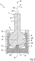
- Fig. 3 is a longitudinal section through a ball joint 1 according to a third embodiment can be seen, wherein the previous embodiments identical or similar features are denoted by the same reference numerals as in the previous embodiments.
- the ball and socket joint 1 has a housing 4 enclosing a spigot opening 2 and an interior 3, a bearing shell 5 arranged in the interior 3, and a ball stud 8 comprising a joint ball 6 and a pin 7 rigidly connected thereto, which with its joint ball 6 is slidably mounted in the bearing shell 5 and extending through the pin opening 2 through out of the housing 4, relative to which the ball stud 8 is deflected.
- the center of the ball joint 6 is designated by the reference M.
- an articulation longitudinal axis 9 which extends in an axial direction x and extends through the center M of the joint ball 6. Furthermore, the ball pin 8 is assigned a through the center M of the ball joint 6 extending pin longitudinal axis 10, with respect to which the ball pin 8 is rotationally symmetrical. The ball pin 8 is shown in a non-deflected state, so that the pin longitudinal axis 10 coincides with the joint longitudinal axis 9. This undeflected position of the ball stud 8 is also referred to as zero position.
- the housing 4 is closed on a side opposite the journal opening 2 by a closure lid, which forms a bottom 14 of the housing.
- the ball joint 6 has on its side facing away from the pin 7 a flattened pole face 11.
- the pole face is not flattened, but forms a part of the spherical surface of the joint ball 6.
- On the pole face 11 is provided in the direction of the journal longitudinal axis 10 in the joint ball 6 extending recess 18 through which the pin longitudinal axis 10 in particular centrally therethrough runs.
- in particular disc-shaped, elastomeric body 13 is arranged, which has on its the ball joint 6 facing surface 12 in the direction of the joint longitudinal axis 9 projecting projection 19 which in the Recess 18 engages.
- the joint longitudinal axis 9 extends in particular centrally through the projection 19.
- the projection 19 is formed by the material of the elastomer body 13 and fixedly connected thereto. Further, the elastomer body 13 is located with its surface facing away from the surface 12 on the bottom 14.
- the ball joint 6 rests with its pole face 11 on the surface 12 of the elastomer body 13.
- the recess 18 and the projection 19 are each formed circular cylindrical, wherein the peripheral contour of the recess 18 is adapted in particular to the peripheral contour of the projection 19 or approximately adapted.
- a deflection of the ball stud 8 in any direction thus leads to a deformation of the elastomer body 13.
- a rotation of the ball pin 8 about the pin longitudinal axis 10 is indicated by the arrow 20.
- the recess 18 and the projection 19 are each formed cuboid, wherein the peripheral contour of the recess 18 is adapted in particular to the peripheral contour of the projection 19 or approximately adapted.
- a deflection of the ball pin 8 in any direction thus leads to a deformation of the elastomer body 13.
- a rotation of the ball pin 8 about the pin longitudinal axis 10 leads to a deformation of the elastomer body 13.
- the recess 18 is formed as an extending in a guide direction groove, wherein the guide direction in Fig. 3 in particular perpendicular to the plane of the drawing.
- the projection 19 is advantageous in the groove in the guide direction, in particular movable, out.
- the groove is also referred to as a guide groove.
- the groove bottom of the groove is curved about a through the center M of the ball joint 6 and perpendicular to the pin longitudinal axis 10 extending straight line 25.
- the groove bottom for example, is flat.
- the ball stud 8 is freely deflectable in the guide direction.
- the joint housing 4 in the region of the pin opening 2 on its outer circumference has an annular bellows groove 15 in or on which a housing 4 surrounding sealing bellows can be defined, extending from the housing 4 to the pin 7 of the ball stud 8 extends, the pin 7 extends through the sealing bellows therethrough.
- the sealing bellows is not shown.
- Fig. 4 is a longitudinal section through a ball joint 1 according to a fourth embodiment can be seen, to the previous embodiments identical or similar features are denoted by the same reference numerals as in the previous embodiments.
- the ball and socket joint 1 comprises a housing 4 comprising a spigot opening 2 and an interior 3, a bearing shell 5 arranged in the interior 3, and a ball stud 8 comprising a joint ball 6 and a pin 7 rigidly connected to the latter, with its ball joint 6 is slidably mounted in the bearing shell 5 and extending through the pin opening 2 through out of the housing 4, relative to which the ball stud 8 is deflected.
- the center of the ball joint 6 is designated by the reference M.
- an articulation longitudinal axis 9 which extends in an axial direction x and extends through the center M of the joint ball 6. Furthermore, the ball pin 8 is assigned a through the center M of the ball joint 6 extending pin longitudinal axis 10, with respect to which the ball pin 8 is rotationally symmetrical. The ball pin 8 is shown in a non-deflected state, so that the pin longitudinal axis 10 coincides with the joint longitudinal axis 9. This undeflected position of the ball stud 8 is also referred to as zero position.
- the housing 4 is closed on a side opposite the journal opening 2 by a closure lid, which forms a bottom 14 of the housing.
- the ball joint 6 has on its side facing away from the pin 7 a flattened pole face 11.
- the pole face is not flattened, but forms part of the spherical surface of the joint ball 6.
- a projection 21 projecting in the direction of the pin longitudinal axis 10 from the joint ball 6 is provided, through which the pin longitudinal axis 10 extends in particular centrally.
- the projection 21 is formed by the material of the ball stud 8 and fixedly connected thereto.
- in particular disc-shaped, elastomer body 13 is arranged, on whose the ball joint 6 facing surface 12 a direction of the longitudinal axis of the joint 9 in the elastomer body 3 extending recess 22 provided is, in which the projection 21 engages.
- the joint longitudinal axis 9 in particular runs centrally through the recess 22.
- the elastomer body 13 lies with its side facing away from the surface 12 against the bottom 14.
- the ball joint 6 rests with its pole face 11 on the surface 12 of the elastomer body 13.
- a plan view of the elastomeric body 13 is made Fig. 5 seen.
- the recess 22 and the projection 21 are each formed circular cylindrical, wherein the peripheral contour of the recess 22 is adapted in particular to the peripheral contour of the projection 21 or approximately adapted.
- a deflection of the ball stud 8 in any direction thus leads to a deformation of the elastomer body 13.
- the ball stud 8 in particular in or at least in the zero position, freely rotatable about its journal longitudinal axis 10.
- a rotation of the ball pin 8 about the journal longitudinal axis 10 is in Fig. 4 indicated by the arrow 20.
- Fig. 6 is a plan view of the elastomeric body 13 according to a first variant visible.
- the recess 22 and the projection 21 are each formed cuboid, wherein the peripheral contour of the recess 22 is adapted in particular to the peripheral contour of the projection 21 or approximately adapted.
- a deflection of the ball pin 8 in any direction thus leads to a deformation of the elastomer body 13.
- a rotation of the ball pin 8 about the pin longitudinal axis 10 leads to a deformation of the elastomer body 13.
- Fig. 7 is a plan view of the elastomeric body 13 according to a second variant visible.
- the recess 22 as a in a guide direction 26 extending groove formed, wherein the guide direction 26 in Fig. 4 in particular perpendicular to the plane of the drawing.
- the groove is also referred to as a guide groove.
- the groove base 23 of the groove is curved about a through the center M of the ball joint 6 and perpendicular to the pin longitudinal axis 10 extending straight line 25.
- the groove bottom for example, is flat.
- the groove width b of the groove is adapted to the projection 21, in particular to the diameter and / or the width of the projection 21, or approximately adapted.
- the groove is dimensioned and / or long that the projection 21 can not press against the groove ends of the groove, which are in particular closed.
- the ball pin 8 in the guide direction 26 is freely deflected. A deflection of the ball stud in a direction other than the guide direction 26, for example in a direction perpendicular to the guide direction 26, in particular leads to an elastic deformation of the elastomer body 13 and thus acting on the ball pin 8 restoring moment.
- Fig. 8 is a plan view of the elastomeric body 13 according to a third variant visible.
- the recess 22 is formed as a groove extending in a guide direction 26, wherein the guide direction 26 in FIG Fig. 4 in particular perpendicular to the plane of the drawing.
- the groove is also referred to as a guide groove.
- the groove bottom of the groove is flat.
- the groove bottom 23 of the groove is curved, for example, around a straight line 25 running through the center M of the ball joint 6 and perpendicular to the pin longitudinal axis 10.
- the groove width b of the groove is adapted to the projection 21, in particular to the diameter and / or the width of the projection 21, or approximately adapted.
- the groove in the guide direction 26 is open at its groove ends.
- the ball pin 8 in the guide direction 26 is freely deflected. A deflection of the ball pin in a direction other than the guide direction 26, for example in a direction perpendicular to the guide direction, in particular leads to an elastic deformation of the elastomer body 13 and thus acting on the ball pin 8 restoring moment.
- the joint housing 4 in the region of the pin opening 2 on its outer circumference has an annular bellows groove 15 in or on which a housing 4 surrounding sealing bellows can be defined, extending from the housing 4 to the pin 7 of the ball stud 8 extends, the pin 7 extends through the sealing bellows therethrough.
- the sealing bellows is not shown.
- Fig. 9 is a longitudinal section through a ball joint 1 according to a fifth embodiment can be seen, to the previous embodiments identical or similar features are denoted by the same reference numerals as in the previous embodiments.
- the ball-and-socket joint 1 has a housing 4 enclosing a spigot opening 2 and an interior 3, a bearing shell 5 arranged in the interior 3, and a ball stud 8 comprising a joint ball 6 and a pin 7 rigidly connected to the latter, with its ball joint 6 is slidably mounted in the bearing shell 5 and extending through the pin opening 2 through out of the housing 4, relative to which the ball stud 8 is deflected.
- the center of the ball joint 6 is designated by the reference M.
- an articulation longitudinal axis 9 which extends in an axial direction x and extends through the center M of the joint ball 6. Furthermore, the ball pin 8 is assigned a through the center M of the ball joint 6 extending pin longitudinal axis 10, with respect to which the ball pin 8 is rotationally symmetrical. The ball pin 8 is shown in a non-deflected state, so that the pin longitudinal axis 10 coincides with the joint longitudinal axis 9. This undeflected position of the ball stud 8 is also referred to as zero position.
- the housing 4 is closed on a side opposite the journal opening 2 by a closure lid, which forms a bottom 14 of the housing.
- the ball joint 6 has on its side facing away from the pin 7 a flattened pole face 11.
- the pole face is not flattened, but forms part of the spherical surface of the joint ball 6.
- a projection 21 projecting in the direction of the pin longitudinal axis 10 from the joint ball 6 is provided, which is preferably arranged eccentrically to the pin longitudinal axis 10, so that it in particular does not or not centrally through the projection 21 runs.
- the projection 21 is formed by the material of the ball stud 8 and fixedly connected thereto.
- in particular disc-shaped, elastomer body 13 is arranged, on whose the ball joint 6 facing surface 12 a direction of the longitudinal axis of the joint 9 in the elastomer body 3 extending recess 22 provided is, in which the projection 21 engages.
- the recess 22 is preferably arranged eccentrically to the housing longitudinal axis 9, so that this particular not or not centrally through the recess 22 extends.
- the ball joint 6 rests with its pole face 11 against the surface 12 of the elastomer body 13. Further, the elastomer body 13 is located with its surface facing away from the surface 12 on the bottom 14.
- the pole face is partially pressed against the elastomer body 13, so that this deformed elastically.
- the elastomer body 13 is elastically deformed by the projection 21 engaging in the recess 22. Due to the elastic deformation of the elastomer body 13 this exerts on the deflected ball pin a restoring moment, which urges the ball pin back to the zero position, which is also referred to here as the neutral position of the ball stud. Since an external force F acts on this to deflect the ball pin 8, if this external force F is removed, the ball pin is returned to the zero position or neutral position by the elastomer body 13.
- FIG. 10 A plan view of the elastomeric body 13 is made Fig. 10 seen.
- the recess 22 and the projection 21 are each formed semi-cylindrical, wherein the peripheral contour of the recess 22 in particular to the peripheral contour of the projection 21 adapted or approximately adapted.
- a rotation of the ball pin 8 about the pin longitudinal axis 10 leads, in particular due to the pin longitudinal axis 10 eccentric arrangement of the projection 21, to a deformation of the elastomer body 13.
- Fig. 11 is a plan view of the elastomeric body 13 according to a first variant visible.
- the recess 22 is formed as a groove extending in a guide direction 26, wherein the guide direction 26 in FIG Fig. 9 in particular perpendicular to the plane of the drawing.
- the projection is formed, for example circular cylindrical.
- the projection 21 is guided in the groove in the guide direction 26.
- the groove is also referred to as a guide groove.
- the groove base 23 of the groove is curved about a through the center M of the ball joint 6 and perpendicular to the pin longitudinal axis 10 extending straight line 25.
- the groove bottom for example, is flat.
- the groove width b of the groove is adapted to the projection 21, in particular to the diameter and / or the width of the projection 21, or approximately adapted.
- a rotation of the ball pin 8 about the pin longitudinal axis 10 leads, in particular due to the pin longitudinal axis 10 eccentric arrangement of the projection 21, to a deformation of the elastomer body 13. Since for turning the ball pin 8 about the pin longitudinal axis 10 acts on this external torque, is omitted this outer torque of the ball pin 8 is rotated back by the elastomer body 13 in a predetermined rotational position with respect to the journal longitudinal axis 10, which is also referred to as zero orientation of the ball stud 8.
- a deflection of the ball stud 8 in Guide 26 thus results in a lower restoring moment than a deflection of the ball stud 8 in a different direction, such as a deflection of the ball stud 8 in the direction of the arrow ⁇ , which extends in particular perpendicular to the guide direction 26.
- the joint housing 4 in the region of the pin opening 2 on its outer circumference has an annular bellows groove 15 in or on which a housing 4 surrounding sealing bellows can be defined, extending from the housing 4 to the pin 7 of the ball stud 8 extends, the pin 7 extends through the sealing bellows therethrough.
- the sealing bellows is not shown.
- Fig. 12 is a longitudinal section through a ball joint 1 according to a sixth embodiment can be seen, to the previous embodiments identical or similar features are denoted by the same reference numerals as in the previous embodiments.
- the ball joint 1 according to the sixth embodiment corresponds to that in FIG Fig. 4 shown ball joint according to the fourth embodiment with the in Fig. 7 shown elastomer body 13 according to the second variant of the fourth embodiment, wherein the view of the ball joint 1 in Fig. 12 opposite to the view in Fig. 4 rotated by 90 ° about the hinge longitudinal axis 9.
- FIG. 14 shows a perspective view of the elastomer body 13 and the ball joint 6 of the ball joint 1 according to the sixth embodiment.
- the projection 21 is formed circular-cylindrical. Furthermore, it can be seen that the groove base 23 is curved. Also is in Fig. 12 the sealing bellows 24 is shown. In addition is in Fig. 12 a deflection of the ball stud in the guide direction indicated by the arrow ⁇ .
Landscapes
- Engineering & Computer Science (AREA)
- General Engineering & Computer Science (AREA)
- Mechanical Engineering (AREA)
- Pivots And Pivotal Connections (AREA)
Applications Claiming Priority (1)
| Application Number | Priority Date | Filing Date | Title |
|---|---|---|---|
| DE102018208475.0A DE102018208475A1 (de) | 2018-05-29 | 2018-05-29 | Kugelgelenk |
Publications (1)
| Publication Number | Publication Date |
|---|---|
| EP3575619A1 true EP3575619A1 (de) | 2019-12-04 |
Family
ID=66323703
Family Applications (1)
| Application Number | Title | Priority Date | Filing Date |
|---|---|---|---|
| EP19171482.3A Withdrawn EP3575619A1 (de) | 2018-05-29 | 2019-04-29 | Kugelgelenk |
Country Status (3)
| Country | Link |
|---|---|
| EP (1) | EP3575619A1 (ko) |
| KR (1) | KR20190135925A (ko) |
| DE (1) | DE102018208475A1 (ko) |
Families Citing this family (1)
| Publication number | Priority date | Publication date | Assignee | Title |
|---|---|---|---|---|
| DE102021203194B3 (de) | 2021-03-30 | 2022-07-21 | Zf Friedrichshafen Ag | Kugelgelenk und Fahrwerkbauteil für ein Kraftfahrzeug und mit einem solchen Kugelgelenk |
Citations (6)
| Publication number | Priority date | Publication date | Assignee | Title |
|---|---|---|---|---|
| US4431328A (en) * | 1979-07-30 | 1984-02-14 | O & S Manufacturing Company | Hemispherical ball and socket joint |
| DE3723548A1 (de) * | 1986-07-16 | 1988-01-21 | Trw Inc | Lagerung fuer ein gelenk |
| US20020012567A1 (en) * | 2000-05-05 | 2002-01-31 | Schmidt George R. | Compliant pivot socket for automotive steering |
| DE20219452U1 (de) * | 2002-09-21 | 2003-04-03 | Orbach Joachim | Punkthalter |
| WO2012154916A2 (en) * | 2011-05-10 | 2012-11-15 | Trw Automotive U.S. Llc | Ball joint |
| GB2496582A (en) * | 2011-11-04 | 2013-05-22 | Goldsmith S College | A ball and socket joint |
-
2018
- 2018-05-29 DE DE102018208475.0A patent/DE102018208475A1/de not_active Ceased
-
2019
- 2019-04-29 EP EP19171482.3A patent/EP3575619A1/de not_active Withdrawn
- 2019-05-24 KR KR1020190061017A patent/KR20190135925A/ko unknown
Patent Citations (6)
| Publication number | Priority date | Publication date | Assignee | Title |
|---|---|---|---|---|
| US4431328A (en) * | 1979-07-30 | 1984-02-14 | O & S Manufacturing Company | Hemispherical ball and socket joint |
| DE3723548A1 (de) * | 1986-07-16 | 1988-01-21 | Trw Inc | Lagerung fuer ein gelenk |
| US20020012567A1 (en) * | 2000-05-05 | 2002-01-31 | Schmidt George R. | Compliant pivot socket for automotive steering |
| DE20219452U1 (de) * | 2002-09-21 | 2003-04-03 | Orbach Joachim | Punkthalter |
| WO2012154916A2 (en) * | 2011-05-10 | 2012-11-15 | Trw Automotive U.S. Llc | Ball joint |
| GB2496582A (en) * | 2011-11-04 | 2013-05-22 | Goldsmith S College | A ball and socket joint |
Also Published As
| Publication number | Publication date |
|---|---|
| KR20190135925A (ko) | 2019-12-09 |
| DE102018208475A1 (de) | 2019-12-05 |
Similar Documents
| Publication | Publication Date | Title |
|---|---|---|
| DE4102863C1 (ko) | ||
| DE19932951A1 (de) | Kugelgelenk | |
| DE60222038T2 (de) | Kugelgelenkdichtung | |
| DE3346665A1 (de) | Elastisches lager mit zwangsfuehrung | |
| EP0353347A1 (de) | Gelenklager, insbesondere für einen Achslenker eines Kraftfahrzeugs | |
| DE3702277A1 (de) | Kugelgelenk | |
| DE4304775C2 (de) | Gelenklager | |
| DE3210954A1 (de) | Kugelgelenk | |
| EP3575619A1 (de) | Kugelgelenk | |
| DE3441019A1 (de) | Wischerarm fuer kraftfahrzeuge | |
| EP1519845A1 (de) | Pendelstütze mit integriertem kugelgelenk | |
| DE102008058239B4 (de) | Buchse | |
| EP0707158A2 (de) | Kugelgelenk für Fahrwerksteile in Kraftfahrzeugen | |
| EP1286070B1 (de) | Tripodegelenk | |
| EP3914506A1 (de) | Kippentkoppelte lenkvorrichtung eines motorrades | |
| DE19629491C2 (de) | Sicherheitsgelenk | |
| DE4305341C2 (de) | Zapfengelenk | |
| EP1756439A1 (de) | Zentralgelenk für einen dreieckslenker von kraftfahrzeugen | |
| DE4420489C2 (de) | Kugelgelenk | |
| DE102014222209B3 (de) | Scharnieranordnung für ein Kraftfahrzeug | |
| EP2565479A1 (de) | Zentrieranordnung an einem Doppelkreuzgelenk | |
| EP1432919B1 (de) | Kugelgelenk | |
| DE10141427A1 (de) | Tripodegelenk | |
| DE3440044C2 (de) | Elastisches Pendelgelenk für Fahrwerksteile in Kraftfahrzeugen | |
| DE102021203194B3 (de) | Kugelgelenk und Fahrwerkbauteil für ein Kraftfahrzeug und mit einem solchen Kugelgelenk |
Legal Events
| Date | Code | Title | Description |
|---|---|---|---|
| PUAI | Public reference made under article 153(3) epc to a published international application that has entered the european phase |
Free format text: ORIGINAL CODE: 0009012 |
|
| AK | Designated contracting states |
Kind code of ref document: A1 Designated state(s): AL AT BE BG CH CY CZ DE DK EE ES FI FR GB GR HR HU IE IS IT LI LT LU LV MC MK MT NL NO PL PT RO RS SE SI SK SM TR |
|
| AX | Request for extension of the european patent |
Extension state: BA ME |
|
| STAA | Information on the status of an ep patent application or granted ep patent |
Free format text: STATUS: THE APPLICATION IS DEEMED TO BE WITHDRAWN |
|
| 18D | Application deemed to be withdrawn |
Effective date: 20200605 |