EP3575603B1 - Scroll compressor having enhanced discharge structure - Google Patents
Scroll compressor having enhanced discharge structure Download PDFInfo
- Publication number
- EP3575603B1 EP3575603B1 EP19176711.0A EP19176711A EP3575603B1 EP 3575603 B1 EP3575603 B1 EP 3575603B1 EP 19176711 A EP19176711 A EP 19176711A EP 3575603 B1 EP3575603 B1 EP 3575603B1
- Authority
- EP
- European Patent Office
- Prior art keywords
- discharge
- orbiting
- compressor
- path
- wrap
- Prior art date
- Legal status (The legal status is an assumption and is not a legal conclusion. Google has not performed a legal analysis and makes no representation as to the accuracy of the status listed.)
- Active
Links
- 239000003507 refrigerant Substances 0.000 claims description 92
- 208000028659 discharge Diseases 0.000 description 230
- 230000006835 compression Effects 0.000 description 99
- 238000007906 compression Methods 0.000 description 99
- 230000008859 change Effects 0.000 description 20
- 230000000694 effects Effects 0.000 description 10
- 230000008901 benefit Effects 0.000 description 6
- 239000012530 fluid Substances 0.000 description 3
- 239000007788 liquid Substances 0.000 description 3
- 230000009471 action Effects 0.000 description 2
- 238000000034 method Methods 0.000 description 2
- 238000001816 cooling Methods 0.000 description 1
- 230000006866 deterioration Effects 0.000 description 1
- 230000007246 mechanism Effects 0.000 description 1
- 230000008569 process Effects 0.000 description 1
- 238000007789 sealing Methods 0.000 description 1
- 230000000153 supplemental effect Effects 0.000 description 1
Images


Classifications
-
- F—MECHANICAL ENGINEERING; LIGHTING; HEATING; WEAPONS; BLASTING
- F04—POSITIVE - DISPLACEMENT MACHINES FOR LIQUIDS; PUMPS FOR LIQUIDS OR ELASTIC FLUIDS
- F04C—ROTARY-PISTON, OR OSCILLATING-PISTON, POSITIVE-DISPLACEMENT MACHINES FOR LIQUIDS; ROTARY-PISTON, OR OSCILLATING-PISTON, POSITIVE-DISPLACEMENT PUMPS
- F04C18/00—Rotary-piston pumps specially adapted for elastic fluids
- F04C18/02—Rotary-piston pumps specially adapted for elastic fluids of arcuate-engagement type, i.e. with circular translatory movement of co-operating members, each member having the same number of teeth or tooth-equivalents
- F04C18/0207—Rotary-piston pumps specially adapted for elastic fluids of arcuate-engagement type, i.e. with circular translatory movement of co-operating members, each member having the same number of teeth or tooth-equivalents both members having co-operating elements in spiral form
- F04C18/0246—Details concerning the involute wraps or their base, e.g. geometry
- F04C18/0269—Details concerning the involute wraps
- F04C18/0292—Ports or channels located in the wrap
-
- F—MECHANICAL ENGINEERING; LIGHTING; HEATING; WEAPONS; BLASTING
- F04—POSITIVE - DISPLACEMENT MACHINES FOR LIQUIDS; PUMPS FOR LIQUIDS OR ELASTIC FLUIDS
- F04C—ROTARY-PISTON, OR OSCILLATING-PISTON, POSITIVE-DISPLACEMENT MACHINES FOR LIQUIDS; ROTARY-PISTON, OR OSCILLATING-PISTON, POSITIVE-DISPLACEMENT PUMPS
- F04C18/00—Rotary-piston pumps specially adapted for elastic fluids
- F04C18/02—Rotary-piston pumps specially adapted for elastic fluids of arcuate-engagement type, i.e. with circular translatory movement of co-operating members, each member having the same number of teeth or tooth-equivalents
- F04C18/0207—Rotary-piston pumps specially adapted for elastic fluids of arcuate-engagement type, i.e. with circular translatory movement of co-operating members, each member having the same number of teeth or tooth-equivalents both members having co-operating elements in spiral form
- F04C18/0215—Rotary-piston pumps specially adapted for elastic fluids of arcuate-engagement type, i.e. with circular translatory movement of co-operating members, each member having the same number of teeth or tooth-equivalents both members having co-operating elements in spiral form where only one member is moving
-
- F—MECHANICAL ENGINEERING; LIGHTING; HEATING; WEAPONS; BLASTING
- F04—POSITIVE - DISPLACEMENT MACHINES FOR LIQUIDS; PUMPS FOR LIQUIDS OR ELASTIC FLUIDS
- F04C—ROTARY-PISTON, OR OSCILLATING-PISTON, POSITIVE-DISPLACEMENT MACHINES FOR LIQUIDS; ROTARY-PISTON, OR OSCILLATING-PISTON, POSITIVE-DISPLACEMENT PUMPS
- F04C18/00—Rotary-piston pumps specially adapted for elastic fluids
- F04C18/02—Rotary-piston pumps specially adapted for elastic fluids of arcuate-engagement type, i.e. with circular translatory movement of co-operating members, each member having the same number of teeth or tooth-equivalents
- F04C18/0207—Rotary-piston pumps specially adapted for elastic fluids of arcuate-engagement type, i.e. with circular translatory movement of co-operating members, each member having the same number of teeth or tooth-equivalents both members having co-operating elements in spiral form
- F04C18/0246—Details concerning the involute wraps or their base, e.g. geometry
- F04C18/0253—Details concerning the base
- F04C18/0261—Details of the ports, e.g. location, number, geometry
-
- F—MECHANICAL ENGINEERING; LIGHTING; HEATING; WEAPONS; BLASTING
- F04—POSITIVE - DISPLACEMENT MACHINES FOR LIQUIDS; PUMPS FOR LIQUIDS OR ELASTIC FLUIDS
- F04C—ROTARY-PISTON, OR OSCILLATING-PISTON, POSITIVE-DISPLACEMENT MACHINES FOR LIQUIDS; ROTARY-PISTON, OR OSCILLATING-PISTON, POSITIVE-DISPLACEMENT PUMPS
- F04C18/00—Rotary-piston pumps specially adapted for elastic fluids
- F04C18/02—Rotary-piston pumps specially adapted for elastic fluids of arcuate-engagement type, i.e. with circular translatory movement of co-operating members, each member having the same number of teeth or tooth-equivalents
- F04C18/0207—Rotary-piston pumps specially adapted for elastic fluids of arcuate-engagement type, i.e. with circular translatory movement of co-operating members, each member having the same number of teeth or tooth-equivalents both members having co-operating elements in spiral form
- F04C18/0246—Details concerning the involute wraps or their base, e.g. geometry
- F04C18/0269—Details concerning the involute wraps
-
- F—MECHANICAL ENGINEERING; LIGHTING; HEATING; WEAPONS; BLASTING
- F04—POSITIVE - DISPLACEMENT MACHINES FOR LIQUIDS; PUMPS FOR LIQUIDS OR ELASTIC FLUIDS
- F04C—ROTARY-PISTON, OR OSCILLATING-PISTON, POSITIVE-DISPLACEMENT MACHINES FOR LIQUIDS; ROTARY-PISTON, OR OSCILLATING-PISTON, POSITIVE-DISPLACEMENT PUMPS
- F04C23/00—Combinations of two or more pumps, each being of rotary-piston or oscillating-piston type, specially adapted for elastic fluids; Pumping installations specially adapted for elastic fluids; Multi-stage pumps specially adapted for elastic fluids
- F04C23/008—Hermetic pumps
-
- F—MECHANICAL ENGINEERING; LIGHTING; HEATING; WEAPONS; BLASTING
- F04—POSITIVE - DISPLACEMENT MACHINES FOR LIQUIDS; PUMPS FOR LIQUIDS OR ELASTIC FLUIDS
- F04C—ROTARY-PISTON, OR OSCILLATING-PISTON, POSITIVE-DISPLACEMENT MACHINES FOR LIQUIDS; ROTARY-PISTON, OR OSCILLATING-PISTON, POSITIVE-DISPLACEMENT PUMPS
- F04C23/00—Combinations of two or more pumps, each being of rotary-piston or oscillating-piston type, specially adapted for elastic fluids; Pumping installations specially adapted for elastic fluids; Multi-stage pumps specially adapted for elastic fluids
- F04C23/02—Pumps characterised by combination with or adaptation to specific driving engines or motors
-
- F—MECHANICAL ENGINEERING; LIGHTING; HEATING; WEAPONS; BLASTING
- F04—POSITIVE - DISPLACEMENT MACHINES FOR LIQUIDS; PUMPS FOR LIQUIDS OR ELASTIC FLUIDS
- F04C—ROTARY-PISTON, OR OSCILLATING-PISTON, POSITIVE-DISPLACEMENT MACHINES FOR LIQUIDS; ROTARY-PISTON, OR OSCILLATING-PISTON, POSITIVE-DISPLACEMENT PUMPS
- F04C29/00—Component parts, details or accessories of pumps or pumping installations, not provided for in groups F04C18/00 - F04C28/00
- F04C29/04—Heating; Cooling; Heat insulation
- F04C29/042—Heating; Cooling; Heat insulation by injecting a fluid
-
- F—MECHANICAL ENGINEERING; LIGHTING; HEATING; WEAPONS; BLASTING
- F04—POSITIVE - DISPLACEMENT MACHINES FOR LIQUIDS; PUMPS FOR LIQUIDS OR ELASTIC FLUIDS
- F04C—ROTARY-PISTON, OR OSCILLATING-PISTON, POSITIVE-DISPLACEMENT MACHINES FOR LIQUIDS; ROTARY-PISTON, OR OSCILLATING-PISTON, POSITIVE-DISPLACEMENT PUMPS
- F04C29/00—Component parts, details or accessories of pumps or pumping installations, not provided for in groups F04C18/00 - F04C28/00
- F04C29/12—Arrangements for admission or discharge of the working fluid, e.g. constructional features of the inlet or outlet
- F04C29/124—Arrangements for admission or discharge of the working fluid, e.g. constructional features of the inlet or outlet with inlet and outlet valves specially adapted for rotary or oscillating piston pumps
- F04C29/126—Arrangements for admission or discharge of the working fluid, e.g. constructional features of the inlet or outlet with inlet and outlet valves specially adapted for rotary or oscillating piston pumps of the non-return type
- F04C29/128—Arrangements for admission or discharge of the working fluid, e.g. constructional features of the inlet or outlet with inlet and outlet valves specially adapted for rotary or oscillating piston pumps of the non-return type of the elastic type, e.g. reed valves
-
- F—MECHANICAL ENGINEERING; LIGHTING; HEATING; WEAPONS; BLASTING
- F04—POSITIVE - DISPLACEMENT MACHINES FOR LIQUIDS; PUMPS FOR LIQUIDS OR ELASTIC FLUIDS
- F04C—ROTARY-PISTON, OR OSCILLATING-PISTON, POSITIVE-DISPLACEMENT MACHINES FOR LIQUIDS; ROTARY-PISTON, OR OSCILLATING-PISTON, POSITIVE-DISPLACEMENT PUMPS
- F04C2210/00—Fluid
- F04C2210/26—Refrigerants with particular properties, e.g. HFC-134a
-
- F—MECHANICAL ENGINEERING; LIGHTING; HEATING; WEAPONS; BLASTING
- F04—POSITIVE - DISPLACEMENT MACHINES FOR LIQUIDS; PUMPS FOR LIQUIDS OR ELASTIC FLUIDS
- F04C—ROTARY-PISTON, OR OSCILLATING-PISTON, POSITIVE-DISPLACEMENT MACHINES FOR LIQUIDS; ROTARY-PISTON, OR OSCILLATING-PISTON, POSITIVE-DISPLACEMENT PUMPS
- F04C2240/00—Components
- F04C2240/10—Stators
-
- F—MECHANICAL ENGINEERING; LIGHTING; HEATING; WEAPONS; BLASTING
- F04—POSITIVE - DISPLACEMENT MACHINES FOR LIQUIDS; PUMPS FOR LIQUIDS OR ELASTIC FLUIDS
- F04C—ROTARY-PISTON, OR OSCILLATING-PISTON, POSITIVE-DISPLACEMENT MACHINES FOR LIQUIDS; ROTARY-PISTON, OR OSCILLATING-PISTON, POSITIVE-DISPLACEMENT PUMPS
- F04C2240/00—Components
- F04C2240/20—Rotors
-
- F—MECHANICAL ENGINEERING; LIGHTING; HEATING; WEAPONS; BLASTING
- F04—POSITIVE - DISPLACEMENT MACHINES FOR LIQUIDS; PUMPS FOR LIQUIDS OR ELASTIC FLUIDS
- F04C—ROTARY-PISTON, OR OSCILLATING-PISTON, POSITIVE-DISPLACEMENT MACHINES FOR LIQUIDS; ROTARY-PISTON, OR OSCILLATING-PISTON, POSITIVE-DISPLACEMENT PUMPS
- F04C2240/00—Components
- F04C2240/30—Casings or housings
-
- F—MECHANICAL ENGINEERING; LIGHTING; HEATING; WEAPONS; BLASTING
- F04—POSITIVE - DISPLACEMENT MACHINES FOR LIQUIDS; PUMPS FOR LIQUIDS OR ELASTIC FLUIDS
- F04C—ROTARY-PISTON, OR OSCILLATING-PISTON, POSITIVE-DISPLACEMENT MACHINES FOR LIQUIDS; ROTARY-PISTON, OR OSCILLATING-PISTON, POSITIVE-DISPLACEMENT PUMPS
- F04C2240/00—Components
- F04C2240/40—Electric motor
-
- F—MECHANICAL ENGINEERING; LIGHTING; HEATING; WEAPONS; BLASTING
- F04—POSITIVE - DISPLACEMENT MACHINES FOR LIQUIDS; PUMPS FOR LIQUIDS OR ELASTIC FLUIDS
- F04C—ROTARY-PISTON, OR OSCILLATING-PISTON, POSITIVE-DISPLACEMENT MACHINES FOR LIQUIDS; ROTARY-PISTON, OR OSCILLATING-PISTON, POSITIVE-DISPLACEMENT PUMPS
- F04C29/00—Component parts, details or accessories of pumps or pumping installations, not provided for in groups F04C18/00 - F04C28/00
- F04C29/02—Lubrication; Lubricant separation
Definitions
- the present invention relates to a scroll compressor, and more particularly, to a scroll compressor having an enhanced discharge structure to discharge a refrigerant compressed in a compression chamber.
- a compressor is an apparatus configured to convert mechanical energy into compression energy of a compressible fluid.
- the compressor may be categorized into a reciprocating compressor, a rotary compressor, a vane compressor, and a scroll compressor in accordance with a method of compressing a fluid.
- the scroll compressor includes a fixed scroll having a fixed wrap and an orbiting scroll having an orbiting wrap engaged with the fixed wrap.
- the scroll compressor allows the orbiting scroll to perform an orbiting movement on the fixed scroll.
- the scroll compressor is provided with a compression chamber formed between the fixed wrap and the orbiting wrap in accordance with the orbiting movement of the orbiting scroll.
- the compression chamber formed between the fixed wrap and the orbiting wrap performs suction and compression of a refrigerant using a continuous volume change.
- the scroll compressor has an advantage capable of obtaining a relatively high compression ratio compared to other types of compressors. Also, the scroll compressor has an advantage capable of obtaining a stable torque because suction, compression, and discharge strokes of a refrigerant are smoothly performed.
- Characteristics of the scroll compressor are determined by shapes of the fixed wrap and the orbiting wrap. Although the fixed wrap and the orbiting wrap may have random shapes, the fixed wrap and the orbiting wrap generally have a form of an involute curve which is easy to process.
- the orbiting scroll generally has an orbiting end plate formed in a circular plate shape and the orbiting wrap formed at one side of the orbiting end plate.
- a scroll compressor in which a point at which an eccentric portion and an orbiting scroll of a rotary shaft are coupled is formed on the same plane (a position at which the eccentric portion and the orbiting scroll overlap along a rotary shaft) as that of the orbiting wrap is disclosed in the Korean Patent Registration No. 10-1059880 , entitled "Scroll Compressor".
- the scroll compressor includes a discharge hole configured to discharge a refrigerant compressed in each compression chamber.
- the refrigerant compressed in the compression chamber is discharged through the discharge hole, however, there is a problem in that it is difficult to make sure of a discharge area of the discharge hole at an initial discharge stage because the discharge hole is covered by the orbiting wrap. If the discharge area is not obtained sufficiently, discharge resistance becomes greater, whereby a smooth discharge is not performed.
- US 2007/036668 A1 relates to a scroll compressor provided with a recess, wherein compression chambers communicate with a discharge port.
- the scroll compressor is of the sort having a wrap with a swing radius that is always equal to or greater than zero.
- a forward ledge of the scroll compressor is defined spaced towards a tip of the scroll wrap relative to a rear ledge.
- a recess in the type of scroll wrap wherein the forward ledge has a thickness that is at least equal to or greater than the thickness of the scroll wrap at the rear ledge.
- a supplemental recess may be provided in the non-orbiting scroll wrap.
- the recess in the orbiting scroll may be stepped to have different height portions.
- US 5 249 943 A relates to a scroll type compressor which includes a fixed scroll and an orbiting scroll.
- Each scroll includes an end plate, a spiral element, at least one airtight compression chamber formed between the fixed and orbiting scrolls, a discharge port, and a drive mechanism for revolving the orbiting scroll relative to the fixed scroll, for compressing fluid in the compression chamber.
- the fixed spiral element and the orbiting spiral element include relatively thick tip portions having oppositely disposed flat faces. These faces are arranged in such a way as to periodically approach each other during the revolution of the orbiting scroll.
- a buffer portion is provided on at least one of the flat faces of the fixed and orbiting tip portions.
- Patent Reference 1 Korean Patent Registration No. 10-1059880 (laid-open date: August 29, 2011 )
- the present invention is directed to a scroll compressor having an enhanced discharge structure that substantially obviates one or more problems due to limitations and disadvantages of the related art.
- An object of the present invention is to provide a scroll compressor having an enhanced discharge structure capable of making sure of a sufficient discharge area at an initial discharge stage to reduce a discharge resistance at an initial discharge stage.
- Another object of the present invention is to provide an auxiliary discharge path structure capable of making sure of a discharge area while maintaining a compression ratio of a scroll compressor.
- Another object of the present invention is to provide a scroll compressor that reduces a problem that an orbiting scroll is subjected to seizure with a fixed scroll.
- a compressor according to the present invention comprises an auxiliary discharge path capable of sufficiently making sure of a discharge area at an initial discharge stage.
- the compressor according to the present invention comprises a fixed scroll including a fixed end plate portion and a fixed wrap, and an orbiting scroll including an orbiting end plate portion and an orbiting wrap, wherein a discharge hole is formed in the fixed end plate portion, and an auxiliary discharge path for connecting a side of the orbiting wrap with a bottom surface of the orbiting wrap is provided to be communicated with the discharge hole, whereby a compressed refrigerant may be discharged through the auxiliary discharge path.
- the compressor according to the present invention provides a structure of an auxiliary discharge path to make sure of a discharge area while maintaining a compression ratio.
- the auxiliary discharge path provides a structure in which an inlet formed at a side of the orbiting wrap is arranged inside a side area of the orbiting wrap that forms a compression chamber at a discharge starting time.
- the compressor of the present invention provides a structure in which an orbiting scroll may be prevented from being subjected to seizure with a fixed scroll.
- the compressor according to the present invention provides a structure in which an auxiliary discharge path is formed on a bottom surface of the orbiting wrap having a friction with the fixed end plate portion in a recessed groove shape.
- the compressor according to the present invention provides a structure in which an auxiliary discharge path is provided at a center portion of an orbiting wrap to discharge a compressed refrigerant through the auxiliary discharge path.
- This structure results in an attenuation effect of discharge loss by enlarging an area to which the compressed refrigerant can be discharged.
- the compressor according to the present invention comprises an auxiliary discharge path connected from a side of an orbiting wrap to a bottom surface of the orbiting wrap, wherein an inlet of the auxiliary discharge path, which is formed at a side, is arranged inside a compression chamber area at a discharge starting time, whereby a discharge area may be enlarged without a change of a compression ratio.
- the compressor according to the present invention comprises an auxiliary discharge path formed on a bottom surface of an orbiting wrap, whereby a fixed end plate portion may be cooled by a refrigerant passing through the auxiliary discharge path.
- the auxiliary discharge path results in reducing a friction area by reducing a sectional area of the bottom surface of the orbiting wrap in which seizure occurs.
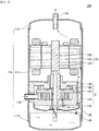
- FIG. 1 is a sectional view illustrating an entire structure of a scroll compressor according to the present invention.
- the scroll compressor to the embodiment of the present invention comprises a casing 110 forming a sealed inner space, a driving motor 120 arranged at an upper portion of the inner space, and a compression portion C performing suction and compression of a refrigerant in accordance with a rotational force of the driving motor.
- the casing 110 includes a cylindrical shell 111 of a cylindrical shape, a first shell coupled to an upper portion of the cylindrical shell 111, and a second shell 113 coupled to a lower portion of the cylindrical shell 111.
- first shell 112 is arranged at the upper portion and the second shell 113 is arranged at the lower portion, the first shell 112 may correspond to an upper shell, and the second shell 113 may correspond to a lower shell.
- a refrigerant suction pipe 116 and a refrigerant dischage portion 118 are coupled to the casing 110.
- a refrigerant is sucked into the compressor 100 through the refrigerant suction pipe 116.
- the sucked refrigerant is compressed in the compression portion C and then discharged from the compressor 100 through the refrigerant dischage portion 118.
- the refrigerant suction pipe 116 may directly be connected to the compression portion C by passing through the cylindrical shell 111.
- the refrigerant dischage portion 118 may be provided in the compressor 100 in a shape passing through the first shell 112.
- the driving motor 120 includes a stator 122, a rotor 124, and a rotary shaft 126.
- the rotary shaft 126 is coupled to the rotor in a single body. Also, the rotary shaft 126 is arranged to pass through the compression portion. The rotary shaft serves to transfer a rotational power to the compression portion.
- the compression portion C includes a main frame 130, a fixed scroll 140, an orbiting scroll 150, an Oldham ring 160, and a discharge cover 170.
- the main frame 130 forms a portion of external appearance of the compression portion C. If the refrigerant dischage portion 118 is arranged toward the upper portion, the main frame 130 may correspond to the upper portion of the compression portion C.
- An outer circumference of the main frame 130 is coupled to an inner circumference of the casing.
- the main frame 130 serves to support the rotary shaft 126 that passes through the main frame 130.
- the main frame 130 maintains a fixed state without being rotated with the rotary shaft 126.
- the fixed scroll 140 may be arranged in the main frame 130 to be far away from the refrigerant dischage portion 118.
- the fixed scroll 140 may be arranged at a lower portion of the main frame 130.
- An outer circumference of the fixed scroll 140 is coupled to the inner circumference of the casing 110.
- the fixed scroll 140 serves to support the rotary shaft 126 that passes through the fixed scroll 140.
- the fixed scroll 140 maintains a fixed state without being rotated with the rotary shaft 126.
- the fixed scroll 140 includes a discharge hole 148 through which a compressed refrigerant is discharged.
- a discharge valve 149 is arranged in the discharge hole 148.
- the discharge valve 149 has a structure which is opened by a pressure of the refrigerant.
- the discharge valve 149 serves to allow the refrigerant which is opened and then compressed to be discharged from the compression chamber if the refrigerant which is discharged reaches a certain pressure.
- the orbiting scroll 150 may be arranged between the main frame 130 and the fixed scroll 140.
- the orbiting scroll 150 may be received in the main frame 130 and the fixed scroll 140.
- the orbiting scroll 150 is coupled to an eccentric portion 126c of the rotary shaft 126.
- the eccentric portion 126c may be provided to be eccentric or protruded from the rotary shaft 126 in a diameter direction.
- the eccentric portion 126c is eccentrically rotated by rotation of the rotary shaft 126.
- the orbiting scroll 150 performs an orbiting movement by means of an eccentric rotation of the eccentric portion 126c.
- the eccentric portion 126c is rotatably coupled to the orbiting scroll 150.
- the Oldham ring 160 is arranged between the orbiting scroll 150 and the main frame 130.
- the Oldham ring 160 serves to allow the orbiting scroll 150 to perform an orbiting movement without performing rotation.
- the discharge cover 170 may be arranged in the fixed scroll 140 to be far away from the refrigerant dischage portion 118.
- the discharge cover 170 may be arranged at the lower portion of the fixed scroll 140.
- the discharge cover 170 may serve to separate the refrigerant and oil, which are discharged from the compression chamber, from each other.
- the oil circulates inside the compressor.
- the oil serves to improve tight sealing of the compression chamber, lubricate friction portions, and cool heat generated from the friction portions.
- the oil moves together with the refrigerant in a state that the oil is mixed with the refrigerant, or is stored by being separated from the refrigerant.
- the oil may be stored in one side of the casing 110.
- the oil may be stored below the lower portion of the casing 110.
- the oil may be stored in a lower space of the discharge cover 170 in the inner space of the casing.
- FIG. 2 is an enlarged view illustrating a compression portion of a compressor according to the present invention
- FIG. 3 is a partially exploded perspective view illustrating a compression portion shown in FIG. 1 .
- the compression portion includes a main frame 130, a fixed scroll 140, an orbiting scroll 150, an Oldham ring 160, and a discharge cover 170.
- the fixed scroll 140 includes a fixed end plate portion 142 having a circular plate shape and a fixed wrap 144 formed to be protruded from the fixed end plate portion 142.
- the discharge hole 148 is formed to pass through the fixed end plate portion 142.
- a portion where the discharge hole 148 is connected with the compression chamber may be referred to as a discharge inlet.
- a portion where the discharge hole 148 is connected with the inside of the discharge cover 170 may be referred to as a discharge outlet.
- the discharge valve 149 is arranged at the discharge outlet.
- the orbiting scroll 150 includes an orbiting end plate portion 152 having a circular plate shape and an orbiting wrap 154 formed to be protruded from the orbiting end plate portion 152.
- the orbiting end plate portion 152 may be arranged in parallel with the fixed end plate portion 142.
- the orbiting wrap 154 may be formed to be protruded toward the fixed end plate portion 142 from one surface of the orbiting end plate portion 152.
- One surface (or bottom surface) of the orbiting wrap 154 may be tightly adhered to the fixed end plate portion 142.
- An exposed surface corresponding to a free end of the orbiting wrap 154 may be in contact with the fixed end plate portion 142.
- the fixed wrap 144 may be formed to be protruded from one surface of the fixed end plate portion 142.
- the fixed wrap 144 may be protruded toward the orbiting end plate portion 152 from the fixed end plate portion 142.
- One surface of the fixed wrap 144 may be tightly adhered to the orbiting end plate portion 152. That is, an exposed surface corresponding to a free end of the fixed wrap 144 may be tightly adhered to the orbiting end plate portion 152.
- the orbiting wrap 154 may be engaged with the fixed wrap 144 to form a sealed space (hereinafter, referred to as compression chamber). If the orbiting wrap 154 performs an orbiting movement, the sealed space moves along a spiral track in a direction of the rotary shaft and its volume is reduced.
- a first compression chamber and a second compression chamber may be formed between the orbiting wrap and the fixed wrap.
- the first compression chamber may be formed between an inner surface of the fixed wrap and an outer surface of the orbiting wrap.
- the first compression chamber and the second compression chamber may move to the discharge hole after suction is completed with a phase difference.
- the first compression chamber and the second compression chamber may be combined with each other in a position close to the discharge hole. That is, the first compression chamber and the second compression chamber may be incorporated into one compression chamber at a position near the discharge hole.
- the fixed scroll 140 is provided with the discharge hole 148 in the fixed end plate portion 142.
- the discharge inlet of the discharge hole 148 may be opened or closed in accordance with the orbiting movement of the orbiting wrap 154.
- the discharge valve 149 is provided at the discharge outlet of the discharge hole 148. Switching of the discharge valve 149 may be adjusted by a pressure of the refrigerant which is discharged.
- the refrigerant which is discharged through the discharge hole 148 may move to the discharge cover 170 and then pass through the driving motor 120 through the compression portion C. Afterwards, the refrigerant may be discharged to the outside of the compressor 100 through the refrigerant dischage portion 118.
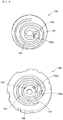
- FIG. 4 is a perspective view respectively illustrating an orbiting scroll and a fixed scroll shown in FIG. 1 .
- discharge holes 148a and 148b are formed in the fixed end plate portion 142 of the fixed scroll 140.
- the discharge hole may include a plurality of discharge holes as shown.
- a discharge hole of a right side may be referred to as a first discharge hole 148a, and another discharge hole may be referred to as a second discharge hole 148b.
- the refrigerant compressed in the compression chamber is discharged to the outside of the compression chamber through the discharge holes 148a and 148b.
- Switching of the discharge holes 148a and 148b is adjusted by the bottom surface of the orbiting wrap 154.
- the refrigerant is resisted when passing through the discharge holes 148a and 148b, and if a discharge area (area opened to move the refrigerant) of the discharge holes 148a and 148b is narrow, a flow velocity becomes fast, whereby discharge resistance is increased.
- the compression chamber formed between the orbiting wrap 154 and the fixed wrap 144 has a volume which is reduced in accordance with the orbiting movement of the orbiting scroll 150, and moves to the center of the orbiting scroll.
- a bypass hole 147 is formed in the fixed end plate portion 142.
- the bypass hole 147 is arranged on a moving path of the compression chamber.
- the bypass hole 147 provides a passage through which an overcompressed refrigerant is discharged.
- a portion where the bypass hole 147 is connected with the compression chamber may be referred to as an inlet, and its opposite portion may be referred to as an outlet.
- a bypass valve (not shown) is arranged at the outlet of the bypass hole 147. Refrigerants of a liquid state may be mixed with each other and sucked into the compression chamber in accordance with an operation state of the compressor. If the refrigerants of the liquid state are mixed, their overcompression may be generated in the compression chamber.
- the bypass hole 147 provides a passage through which the overcompressed refrigerant is discharged.
- the refrigerant discharged through the bypass hole 147 moves to the inside of the discharge cover 170 in the same manner as the refrigerant discharged through the discharge holes 148a and 148b.
- the compressor of the related art provides a structure in which a compressed refrigerant is discharged through the discharge holes 148a and 148b formed in the fixed scroll 140.
- This structure has a drawback in that discharge loss is increased due to a narrow discharge area of the discharge hole at the initial discharge stage.
- the compressor according to the present invention is characterized in that an auxiliary discharge path 156 is provided in the orbiting scroll 150.
- the auxiliary discharge path 156 serves to allow the refrigerant compressed at a discharge starting time to be discharged to the discharge hole 148a or 148b by passing through the auxiliary discharge path 156.
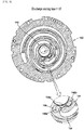
- FIG. 5 is a partially exploded perspective view illustrating an orbiting scroll according to the first embodiment of the present invention.
- the orbiting scroll 150 includes an orbiting end plate portion 152 having a circular plate shape, an orbiting wrap 154 formed to be protruded from the orbiting end plate portion 152 at a certain height, and an auxiliary discharge path 156 formed at a center portion of the orbiting wrap 154 in a groove shape which is recessed.
- the compressor according to the first embodiment of the present invention includes the auxiliary discharge path 156 at the center portion of the orbiting scroll.
- the auxiliary discharge path 156 is formed on the bottom of the orbiting wrap 154 in a recessed groove shape. Also, the auxiliary discharge path 156 is formed to partially remove a side of the orbiting wrap 154, whereby an inlet 156a is formed at the side of the orbiting wrap 154.
- the auxiliary discharge path 156 may be provided in such a manner that the side of the orbiting wrap 154 is partially recessed. Therefore, the auxiliary discharge path 156 may form the inlet 156a through which the refrigerant of the compression chamber enters one surface of the orbiting wrap 154.
- the inlet 156a of the auxiliary discharge path 156 is arranged inside a side area of the orbiting wrap, which forms the compression chamber at a discharge starting time.
- the inlet 156a of the auxiliary discharge path 156 is to maintain a compression ratio by allowing the refrigerant not to move between the compression chambers therethrough.
- the inlet 156a of the auxiliary discharge path 156 forms a wall of a single compression chamber until the discharge starts. If the inlet 156a of the auxiliary discharge path 156 is formed over two compression chambers, compression efficiency may be deteriorated due to movement of the refrigerant between the two compression chambers.
- the auxiliary discharge path 156 may be provided such that its inlet faces the compression chamber provided near the discharge hole 148.
- the auxiliary discharge path 156 may be provided such that its inlet is arranged to be far away from the rotary shaft 120.
- the compressor according to the present invention does not give a change in a crank angle of the discharge starting time because the inlet 156a of the auxiliary discharge path 156 formed in the orbiting wrap 154 is arranged inside the side area, which forms the compression chamber at the discharge starting time. Therefore, the compressor according to the present invention may increase a discharge area of the discharge hole without reducing the compression ratio.
- the auxiliary discharge path is formed on one surface (or bottom surface) of the center portion of the orbiting wrap in a recessed groove shape.
- the bottom surface close to the center portion of the orbiting wrap 154 is partially removed. That is, the auxiliary discharge path may be provided in such a manner that an exposed surface of the center portion of the orbiting wrap is recessed.
- the bottom surface of the center portion of the orbiting wrap is a portion tightly adhered to the fixed end plate portion 142 ( FIG. 4 ).
- the bottom surface of the center portion of the orbiting wrap 154 may be subjected to seizure with the fixed end plate portion 142 during operation of the compressor.
- a partial area of the bottom surface of the center portion of the orbiting wrap according to the present invention becomes the auxiliary discharge path 156, an area of a portion subjected to seizure with the fixed end plate portion 142 may be reduced.
- the refrigerant moves through the auxiliary discharge path 156, and the surface of the fixed end plate portion 142 may be cooled by the refrigerant which is moving, whereby seizure of the orbiting wrap may be more avoided. Also, since the oil moves together with the refrigerant, the oil may be supplied between one surface of the orbiting wrap and the fixed end plate portion.
- the auxiliary discharge path 156 has a groove shape from which a certain area is removed from one surface of the orbiting wrap 154.
- the auxiliary discharge path 156 is formed over the bottom surface (exposed surface) of the orbiting wrap 154 and the side of the orbiting wrap 154.
- a side section of the orbiting wrap 154 removed by the auxiliary discharge path 156 becomes the inlet 156a of the auxiliary discharge path 156, and a bottom section of the orbiting wrap 154 removed by the auxiliary discharge path 156 becomes the outlet of the auxiliary discharge path 156.
- the refrigerant compressed in the compression chamber enters the inlet of the auxiliary discharge path 156 formed at the side of the orbiting wrap 154 and is discharged through the discharge hole 148a or 148b ( FIG. 4 ) formed in the fixed scroll by passing through the outlet of the auxiliary discharge path formed on the bottom surface of the orbiting wrap 154.
- the inlet 156a of the auxiliary discharge path 156 is arranged inside a compression chamber area at the discharge starting time. This is to maintain the compression ratio of the compressor.
- line F1 and line F2 denote lines where the orbiting wrap adjoins the fixed wrap at the discharge starting time.
- the inlet 156a of the auxiliary discharge path 156 is arranged between the line F1 and the line F2.
- the refrigerant passes through the inlet of the auxiliary discharge path 156 at the portion where the orbiting wrap adjoins the fixed wrap during compression. At this time, the refrigerant may move (leak) between the compression chambers. If leakage of the refrigerant occurs between the compression chambers before the discharge starting time, a problem may occur in that efficiency of the compressor is deteriorated or the compression ratio is lowered.
- a depth of the auxiliary discharge path 156 is formed within the range of 10% to 30% of a height of the orbiting wrap. If the depth of the auxiliary discharge path 156 is formed to be less than 10%, a discharge area additionally obtained through the inlet 156a of the auxiliary discharge path 156 is small, whereby an attenuation effect of discharge resistance is low. If the depth of the auxiliary discharge path 156 exceeds 30%, a volume of the auxiliary discharge path 156 is increased, whereby a problem occurs in that a flow rate of the refrigerant staying in the auxiliary discharge path 156 is increased.
- the auxiliary discharge path 156 formed in the orbiting wrap 154 reduces a problem that the orbiting wrap 154 is subjected to seizure with the fixed end plate portion of the fixed scroll.
- the center portion of the orbiting wrap 154 has a friction area with the fixed end plate portion, which is relatively greater than the other portion of the orbiting wrap. Also, the center portion of the orbiting wrap 154 has a moving speed which is relatively slow with respect to the fixed end plate portion. Therefore, the center portion of the orbiting wrap 154 is more likely to be subjected to seizure with the fixed end plate portion 142 than the other portion of the orbiting wrap 154. Seizure of the orbiting wrap 154 may be generated due to a lack or overheat of oil.
- the orbiting wrap according to the present invention includes the auxiliary discharge path 156 at the center portion.
- the auxiliary discharge path 156 is formed in a shape from which the center portion of the orbiting wrap 154 is removed, whereby a downsizing effect of a friction area with the fixed end plate portion is obtained. Also, the refrigerant moves through the auxiliary discharge path 156, and a cooling effect of the fixed end plate portion 142 which is in contact with the refrigerant is obtained.
- the auxiliary discharge path 156 formed in the orbiting wrap 154 results in an attenuation effect of seizure between the orbiting wrap 154 and the fixed wrap 144.
- FIG. 6 is a partially exploded perspective view illustrating an orbiting scroll according to the second embodiment of the present invention.
- the auxiliary discharge path of the orbiting scroll according to the second embodiment of the present invention includes an inlet path 158 and an outlet path 159.
- the refrigerant of the compression chamber may enter the inlet path 158 and then move to the outlet path 159.
- the inlet path 158 is formed toward the inside of the orbiting wrap 154 from the side of the orbiting wrap 154.
- the outlet path 159 is formed inside the orbiting wrap 154 to be communicated with the inlet path 158 on the bottom surface of the orbiting wrap 154.
- the auxiliary discharge path 156 of the first embodiment has a single groove shape for connecting the side of the orbiting wrap 154 with the bottom surface
- the auxiliary discharge paths 158 and 159 of the second embodiment have a structure in which the inlet path 158 connected to the side of the orbiting wrap 154 and the outlet path 150 connected to the bottom surface of the orbiting wrap 154 are connected with each other.
- the auxiliary discharge paths 158 and 159 of the second embodiment may be provided to pass through the orbiting wrap.
- the inlet path 158 is formed toward the inside from the side of the orbiting wrap 154 in a horizontal direction. That is, the inlet path 158 may be provided to pass through the center portion of the orbiting wrap 154 in a diameter direction of the rotary shaft or a direction inclined with respect to the rotary shaft.
- the outlet path 159 is formed on one surface of the orbiting wrap 154 in a longitudinal direction to be communicated with the inlet path 158. That is, the outlet path 159 may be provided to be communicated with the inlet path 158 on one surface where the orbiting wrap 154 faces the fixed scroll by passing through the orbiting wrap 154.
- the refrigerant compressed in the compression chamber may be discharged to the discharge hole by passing through the inlet path 158 and the outlet path 159.
- the inlet 158a of the inlet path 158 is arranged inside the compression chamber area at the discharge starting time in the same manner as the first embodiment.
- one inlet path 158 and one outlet path 159 may be formed or a plurality of outlet paths 159 may be formed.
- the auxiliary discharge path of the second embodiment results in an enlarging effect of the discharge area and an attenuation effect of seizure of the orbiting wrap in the same manner as the auxiliary discharge path of the first embodiment.
- FIGS. 7 to 11 are views illustrating positions of a discharge hole and an auxiliary discharge path every 10° until a crank angle is additionally rotated at 40° from a discharge starting time of a compressor according to the first embodiment of the present invention.
- FIG. 7 illustrates a discharge starting time.
- the first discharge hole 148a is fully covered by the bottom surface of the orbiting wrap 154, and a lower portion of the second discharge hole 148b is partially opened to the compression chamber.
- the compressed refrigerant may enter the auxiliary discharge path 156 through the inlet 156a of the auxiliary discharge path 156 and then be discharged through the first discharge hole 148a overlapped with the auxiliary discharge path 156.
- the refrigerant entering the inlet 156a of the auxiliary discharge path 156 may be discharged through the second discharge hole 148b overlapped with the auxiliary discharge path 156.
- the compressor according to the present invention may make sure of additional refrigerant discharge path through the auxiliary discharge path 156 formed in the orbiting wrap 154. This substantially results in an enlarging effect of an effective discharge area of the discharge hole.
- the auxiliary discharge path 156 is arranged at an end area inside the orbiting wrap 154.
- An overlap area of the auxiliary discharge path 156 with the discharge holes 148a and 148b is changed in accordance with an orbiting movement of the orbiting wrap 154.
- a wider area of the auxiliary discharge path 156 is overlapped with the first discharge hole 148a.
- the overlap area of the auxiliary discharge path 156 with the first discharge hole 148a exists even before the discharge starting time.
- the discharge valve 149 ( FIG. 2 ) is provided at the discharge outlet of the discharge holes 148a and 148b, the discharge valve 149 is not opened if the refrigerant does not reach a discharge pressure even though the refrigerant enters the auxiliary discharge path 156 before the discharge starting time.
- the auxiliary discharge path 156 is overlapped with the discharge holes 148a and 148b before the discharge starting time, the discharge through the auxiliary discharge path 156 may be blocked by the discharge valve 149.
- FIG. 8 illustrates a state that a crank angle is rotated by addition of 10° at a discharge starting time.
- the discharge area of the second discharge hole opened to the compression chamber is downsized and the first discharge hole 148a starts to open.
- the entire discharge area of the discharge hole is narrow even in this state.
- auxiliary discharge path 156 has a sufficient overlap area with the first discharge hole 148a and an overlap area with the second discharge hole 148b is close to twice of an area of the second discharge hole 148b directly opened to the compression chamber.
- the area of the second discharge hole 148b opened to the compression chamber is reduced while the crank angle is being rotated by addition of 10° from the discharge starting time and the area of the first discharge hole 148a opened to the compression chamber is increased but the discharge area of the discharge hole is not sufficient by only these areas.
- auxiliary discharge hole 156 is formed in the orbiting wrap, since the area of the first discharge hole 148a and the second discharge area 148b covered by the orbiting wrap 154 may be used through the auxiliary discharge path 156, this substantially results in an enlarging effect of the discharge area.
- FIG. 9 is a view illustrating a state that a crank angle is rotated by addition of 20° at a discharge starting time.
- auxiliary discharge path 156 has a sufficient overlap area with the first discharge hole 148a and an overlap area with the second discharge hole 148b is close to twice of an area of the second discharge hole 148b directly opened to the compression chamber.
- the compressed refrigerant may be discharge through the first discharge hole 148a overlapped with the auxiliary discharge path 156 and the second discharge hole 148b overlapped with the auxiliary discharge path 156 after passing through the inlet 156a of the auxiliary discharge path 156.
- FIG. 10 is a view illustrating a state that a crank angle is rotated by addition of 30° at a discharge starting time.
- the discharge area of the first discharge hole 148a is 5% or less of the entire area of the first discharge hole 148a even in the state of FIG. 10 .
- auxiliary discharge path 156 has an overlap area with the first discharge hole 148a within the range of 50% or more of the entire area of the first discharge hole 148a.
- the discharge area of the discharge paths 148a and 148b is narrow until the crank angle is rotated by addition of 30° at the discharge starting time, and thus it is useful to make sure of the discharge area through the auxiliary discharge path 156.
- FIG. 11 is a view illustrating a state that a crank angle is rotated by addition of 40° at a discharge starting time.
- the auxiliary discharge path 156 still makes sure of a sufficient area overlapped with the first discharge hole 148a.
- the auxiliary discharge path 156 results in an enlarging effect of an effective discharge area of the discharge hole by providing additional path through which the compressed refrigerant is discharged. Enlargement of the effective discharge area reduces a flow velocity of the refrigerant and discharge resistance.
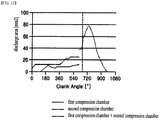
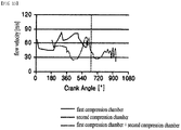
- FIG. 12 is a graph illustrating a change of an open area of a discharge inlet according to a change of a crank angle of a compressor which is not provided with an auxiliary discharge path
- FIG. 13 is a graph illustrating a change of a flow velocity of a refrigerant according to a change of a crank angle of a compressor which is not provided with an auxiliary discharge path.
- a discharge area opened to the first compression chamber and a discharge area opened to the second compression chamber are changed in accordance with a change of the crank angle.
- the first compression chamber and the second compression chamber are incorporated into one before the discharge starting time.
- the discharge area includes an open area of the bypass hole 147 ( FIG. 7 ) arranged on the moving path of the compression chamber.
- the bypass hole is intended to prevent the refrigerant from being overcompressed when the refrigerant of a liquid state enters there and to allow the compressed refrigerant to be discharged.
- a flow velocity of the refrigerant is a numerical value obtained by dividing a volume downsizing rate of the compression chamber by an open area and then reversely counting the divided value.
- a dotted line denotes a point of a crank angle of 660° which is the discharge starting point.
- an interval (interval of a crank angle of 660° or more) corresponding to the time after the discharge starting time is significant in the graph.
- the first compression chamber and the second compression chamber are incorporated into one before the discharge starting time.
- the open area of the discharge hole is measured at 50mm 2 , approximately at the discharge starting time.
- the flow velocity is measured at 49.6m/s at the discharge starting time.
- FIG. 14 is a graph illustrating a change of an open area of a discharge inlet according to a change of a crank angle of a compressor which is provided with an auxiliary discharge path in accordance with the first embodiment of the present invention
- FIG. 15 is a graph illustrating a change of a flow velocity of a refrigerant according to a change of a crank angle of a compressor which is provided with an auxiliary discharge path in accordance with the first embodiment of the present invention.
- the orbiting wrap has a height of 23mm
- the auxiliary discharge path has a depth of 3mm
- the discharge starting time is a point of a crank angle of 660°.
- the open area of the discharge hole at the discharge starting time is measured at 60mm 2 , approximately.
- a flow velocity at the discharge starting time is measured at 42.2mm/s.
- the open area is increased as much as 10mm 2 (20%), approximately.
- the flow velocity of the refrigerant is reduced as much as 7.4mm/s (15%), approximately.
- Discharge loss may be devised from the flow velocity of the refrigerant which is discharged.
- Discharge loss is proportional to kinetic energy of the refrigerant which is discharged. This is because that kinetic energy of the refrigerant which is discharged is generated from a work of the compressor.
- a difference of discharge loss according to the presence of the auxiliary discharge path may simply be checked by a ratio of a value obtained by multiplying the square of the flow rate and the square of the velocity.
- the value obtained by multiplying the square of the flow rate and the square of the velocity in the compressor which is not provided with the auxiliary discharge path of FIGS. 12 and 13 is computed as 90.2m 5 /s 3
- the value obtained by multiplying the square of the flow rate and the square of the velocity in the compressor which is provided with the auxiliary discharge path of FIGS. 14 and 15 is computed as 66.9m 5 /s 3 .
- discharge loss is reduced as much as 26% because the auxiliary discharge path is formed.
Description
- This application claims the benefit of the
Korean Patent Application No. 10-2018-0060759 filed on May 28, 2018 - The present invention relates to a scroll compressor, and more particularly, to a scroll compressor having an enhanced discharge structure to discharge a refrigerant compressed in a compression chamber.
- Generally, a compressor is an apparatus configured to convert mechanical energy into compression energy of a compressible fluid. The compressor may be categorized into a reciprocating compressor, a rotary compressor, a vane compressor, and a scroll compressor in accordance with a method of compressing a fluid.
- The scroll compressor includes a fixed scroll having a fixed wrap and an orbiting scroll having an orbiting wrap engaged with the fixed wrap. The scroll compressor allows the orbiting scroll to perform an orbiting movement on the fixed scroll.
- The scroll compressor is provided with a compression chamber formed between the fixed wrap and the orbiting wrap in accordance with the orbiting movement of the orbiting scroll. The compression chamber formed between the fixed wrap and the orbiting wrap performs suction and compression of a refrigerant using a continuous volume change.
- The scroll compressor has an advantage capable of obtaining a relatively high compression ratio compared to other types of compressors. Also, the scroll compressor has an advantage capable of obtaining a stable torque because suction, compression, and discharge strokes of a refrigerant are smoothly performed.
- Characteristics of the scroll compressor are determined by shapes of the fixed wrap and the orbiting wrap. Although the fixed wrap and the orbiting wrap may have random shapes, the fixed wrap and the orbiting wrap generally have a form of an involute curve which is easy to process.
- The orbiting scroll generally has an orbiting end plate formed in a circular plate shape and the orbiting wrap formed at one side of the orbiting end plate.
- A scroll compressor in which a point at which an eccentric portion and an orbiting scroll of a rotary shaft are coupled is formed on the same plane (a position at which the eccentric portion and the orbiting scroll overlap along a rotary shaft) as that of the orbiting wrap is disclosed in the
Korean Patent Registration No. 10-1059880 - In the scroll compressor having the above structure, since an action point on which a repulsive point of a refrigerant acts and an action point of a reaction force opposite to the repulsive force act at a same height in directions opposite to each other, a problem in which the orbiting scroll is inclined may be solved.
- The scroll compressor includes a discharge hole configured to discharge a refrigerant compressed in each compression chamber. The refrigerant compressed in the compression chamber is discharged through the discharge hole, however, there is a problem in that it is difficult to make sure of a discharge area of the discharge hole at an initial discharge stage because the discharge hole is covered by the orbiting wrap. If the discharge area is not obtained sufficiently, discharge resistance becomes greater, whereby a smooth discharge is not performed.
- However, if the discharge hole is processed at a great size to enlarge a discharge area, a crank angle in which the compression chamber and the discharge hole start to be communicated with each other is brought forward. If the crank angle in which the compression chamber and the discharge hole are communicated with each other is brought forward, deterioration of a compression ratio occurs. Therefore, there is a limitation in that a size of the discharge hole cannot be enlarged to maintain the compression ratio.
-
US 2007/036668 A1 relates to a scroll compressor provided with a recess, wherein compression chambers communicate with a discharge port. The scroll compressor is of the sort having a wrap with a swing radius that is always equal to or greater than zero. A forward ledge of the scroll compressor is defined spaced towards a tip of the scroll wrap relative to a rear ledge. A recess in the type of scroll wrap wherein the forward ledge has a thickness that is at least equal to or greater than the thickness of the scroll wrap at the rear ledge. A supplemental recess may be provided in the non-orbiting scroll wrap. The recess in the orbiting scroll may be stepped to have different height portions. -
US 5 249 943 A relates to a scroll type compressor which includes a fixed scroll and an orbiting scroll. Each scroll includes an end plate, a spiral element, at least one airtight compression chamber formed between the fixed and orbiting scrolls, a discharge port, and a drive mechanism for revolving the orbiting scroll relative to the fixed scroll, for compressing fluid in the compression chamber. The fixed spiral element and the orbiting spiral element include relatively thick tip portions having oppositely disposed flat faces. These faces are arranged in such a way as to periodically approach each other during the revolution of the orbiting scroll. A buffer portion is provided on at least one of the flat faces of the fixed and orbiting tip portions. - (Patent Reference 1)
Korean Patent Registration No. 10-1059880 (laid-open date: August 29, 2011 - Accordingly, the present invention is directed to a scroll compressor having an enhanced discharge structure that substantially obviates one or more problems due to limitations and disadvantages of the related art.
- An object of the present invention is to provide a scroll compressor having an enhanced discharge structure capable of making sure of a sufficient discharge area at an initial discharge stage to reduce a discharge resistance at an initial discharge stage.
- Another object of the present invention is to provide an auxiliary discharge path structure capable of making sure of a discharge area while maintaining a compression ratio of a scroll compressor.
- Other object of the present invention is to provide a scroll compressor that reduces a problem that an orbiting scroll is subjected to seizure with a fixed scroll.
- Additional advantages, objects, and features of the invention will be set forth in part in the description which follows and in part will become apparent to those having ordinary skill in the art upon examination of the following or may be learned from practice of the invention. The objectives and other advantages of the invention may be realized and attained by the structure particularly pointed out in the written description and claims hereof as well as the appended drawings.
- To achieve these objects and other advantages and in accordance with the purpose of the invention, as embodied and broadly described herein, a compressor according to the present invention comprises an auxiliary discharge path capable of sufficiently making sure of a discharge area at an initial discharge stage. The compressor according to the present invention comprises a fixed scroll including a fixed end plate portion and a fixed wrap, and an orbiting scroll including an orbiting end plate portion and an orbiting wrap, wherein a discharge hole is formed in the fixed end plate portion, and an auxiliary discharge path for connecting a side of the orbiting wrap with a bottom surface of the orbiting wrap is provided to be communicated with the discharge hole, whereby a compressed refrigerant may be discharged through the auxiliary discharge path.
- The compressor according to the present invention provides a structure of an auxiliary discharge path to make sure of a discharge area while maintaining a compression ratio. To this end, the auxiliary discharge path provides a structure in which an inlet formed at a side of the orbiting wrap is arranged inside a side area of the orbiting wrap that forms a compression chamber at a discharge starting time.
- Also, the compressor of the present invention provides a structure in which an orbiting scroll may be prevented from being subjected to seizure with a fixed scroll. To this end, the compressor according to the present invention provides a structure in which an auxiliary discharge path is formed on a bottom surface of the orbiting wrap having a friction with the fixed end plate portion in a recessed groove shape.
- The compressor according to the present invention provides a structure in which an auxiliary discharge path is provided at a center portion of an orbiting wrap to discharge a compressed refrigerant through the auxiliary discharge path. This structure results in an attenuation effect of discharge loss by enlarging an area to which the compressed refrigerant can be discharged.
- The compressor according to the present invention comprises an auxiliary discharge path connected from a side of an orbiting wrap to a bottom surface of the orbiting wrap, wherein an inlet of the auxiliary discharge path, which is formed at a side, is arranged inside a compression chamber area at a discharge starting time, whereby a discharge area may be enlarged without a change of a compression ratio.
- Also, the compressor according to the present invention comprises an auxiliary discharge path formed on a bottom surface of an orbiting wrap, whereby a fixed end plate portion may be cooled by a refrigerant passing through the auxiliary discharge path. The auxiliary discharge path results in reducing a friction area by reducing a sectional area of the bottom surface of the orbiting wrap in which seizure occurs. As a result, a problem that the bottom surface of the orbiting wrap is subjected to seizure with the fixed end plate portion may be solved.
- It is to be understood that both the foregoing general description and the following detailed description of the present invention are exemplary and explanatory and are intended to provide further explanation of the invention as claimed.
- The accompanying drawings, which are included to provide a further understanding of the invention and are incorporated in and constitute a part of this application, illustrate embodiment(s) of the invention and together with the description serve to explain the principle of the invention. In the drawings:
-
FIG. 1 is a sectional view illustrating an entire structure of a scroll compressor according to the present invention; -
FIG. 2 is an enlarged view illustrating a compression portion of a compressor according to the present invention; -
FIG. 3 is a partially exploded perspective view illustrating a compression portion shown inFIG. 1 ; -
FIG. 4 is a perspective view respectively illustrating an orbiting scroll and a fixed scroll shown inFIG. 1 ; -
FIG. 5 is a partially exploded perspective view illustrating an orbiting scroll according to the first embodiment of the present invention; -
FIG. 6 is a partially exploded perspective view illustrating an orbiting scroll according to the second embodiment of the present invention; -
FIG. 7 is a view illustrating positions of a discharge hole and an auxiliary discharge path at a discharge starting time of a compressor according to the first embodiment of the present invention; -
FIG. 8 is a view illustrating a state that a crank angle is rotated by addition of 10° at a discharge starting time inFIG. 7 ; -
FIG. 9 is a view illustrating a state that a crank angle is rotated by addition of 20° at a discharge starting time inFIG. 7 ; -
FIG. 10 is a view illustrating a state that a crank angle is rotated by addition of 30° at a discharge starting time inFIG. 7 ; -
FIG. 11 is a view illustrating a state that a crank angle is rotated by addition of 40° at a discharge starting time inFIG. 7 ; -
FIG. 12 is a graph illustrating a change of an open area of a discharge inlet according to a change of a crank angle of a compressor which is not provided with an auxiliary discharge path; -
FIG. 13 is a graph illustrating a change of a flow velocity of a refrigerant according to a change of a crank angle of a compressor which is not provided with an auxiliary discharge path; -
FIG. 14 is a graph illustrating a change of an open area of a discharge inlet according to a change of a crank angle of a compressor which is provided with an auxiliary discharge path in accordance with the first embodiment of the present invention; and -
FIG. 15 is a graph illustrating a change of a flow velocity of a refrigerant according to a change of a crank angle of a compressor which is provided with an auxiliary discharge path in accordance with the first embodiment of the present invention. - Reference will now be made in detail to the detailed embodiments of the present invention, examples of which are illustrated in the accompanying drawings. The present invention is not limited to the embodiments as suggested, and the skilled person may easily devise other embodiments within the range of the appended claims.
- Hereinafter, the preferred embodiments of the present invention will be described in detail with reference to the accompanying drawings. Wherever possible, the same reference numbers will be used throughout the drawings to refer to the same or like parts.
-
FIG. 1 is a sectional view illustrating an entire structure of a scroll compressor according to the present invention. - The scroll compressor to the embodiment of the present invention comprises a
casing 110 forming a sealed inner space, a drivingmotor 120 arranged at an upper portion of the inner space, and a compression portion C performing suction and compression of a refrigerant in accordance with a rotational force of the driving motor. - The
casing 110 includes acylindrical shell 111 of a cylindrical shape, a first shell coupled to an upper portion of thecylindrical shell 111, and asecond shell 113 coupled to a lower portion of thecylindrical shell 111. - If the
first shell 112 is arranged at the upper portion and thesecond shell 113 is arranged at the lower portion, thefirst shell 112 may correspond to an upper shell, and thesecond shell 113 may correspond to a lower shell. - A
refrigerant suction pipe 116 and arefrigerant dischage portion 118 are coupled to thecasing 110. A refrigerant is sucked into thecompressor 100 through therefrigerant suction pipe 116. The sucked refrigerant is compressed in the compression portion C and then discharged from thecompressor 100 through therefrigerant dischage portion 118. - As shown, the
refrigerant suction pipe 116 may directly be connected to the compression portion C by passing through thecylindrical shell 111. Therefrigerant dischage portion 118 may be provided in thecompressor 100 in a shape passing through thefirst shell 112. - The driving
motor 120 includes astator 122, arotor 124, and arotary shaft 126. Therotary shaft 126 is coupled to the rotor in a single body. Also, therotary shaft 126 is arranged to pass through the compression portion. The rotary shaft serves to transfer a rotational power to the compression portion. - The compression portion C includes a
main frame 130, afixed scroll 140, anorbiting scroll 150, anOldham ring 160, and adischarge cover 170. - The
main frame 130 forms a portion of external appearance of the compression portion C. If therefrigerant dischage portion 118 is arranged toward the upper portion, themain frame 130 may correspond to the upper portion of the compression portion C. - An outer circumference of the
main frame 130 is coupled to an inner circumference of the casing. Themain frame 130 serves to support therotary shaft 126 that passes through themain frame 130. Themain frame 130 maintains a fixed state without being rotated with therotary shaft 126. - The fixed
scroll 140 may be arranged in themain frame 130 to be far away from therefrigerant dischage portion 118. For example, the fixedscroll 140 may be arranged at a lower portion of themain frame 130. An outer circumference of the fixedscroll 140 is coupled to the inner circumference of thecasing 110. The fixedscroll 140 serves to support therotary shaft 126 that passes through the fixedscroll 140. The fixedscroll 140 maintains a fixed state without being rotated with therotary shaft 126. - The fixed
scroll 140 includes adischarge hole 148 through which a compressed refrigerant is discharged. Adischarge valve 149 is arranged in thedischarge hole 148. Thedischarge valve 149 has a structure which is opened by a pressure of the refrigerant. Thedischarge valve 149 serves to allow the refrigerant which is opened and then compressed to be discharged from the compression chamber if the refrigerant which is discharged reaches a certain pressure. - The
orbiting scroll 150 may be arranged between themain frame 130 and the fixedscroll 140. Theorbiting scroll 150 may be received in themain frame 130 and the fixedscroll 140. Theorbiting scroll 150 is coupled to an eccentric portion 126c of therotary shaft 126. The eccentric portion 126c may be provided to be eccentric or protruded from therotary shaft 126 in a diameter direction. The eccentric portion 126c is eccentrically rotated by rotation of therotary shaft 126. Theorbiting scroll 150 performs an orbiting movement by means of an eccentric rotation of the eccentric portion 126c. - The eccentric portion 126c is rotatably coupled to the
orbiting scroll 150. - The
Oldham ring 160 is arranged between the orbitingscroll 150 and themain frame 130. TheOldham ring 160 serves to allow theorbiting scroll 150 to perform an orbiting movement without performing rotation. - The
discharge cover 170 may be arranged in the fixedscroll 140 to be far away from therefrigerant dischage portion 118. For example, thedischarge cover 170 may be arranged at the lower portion of the fixedscroll 140. Thedischarge cover 170 may serve to separate the refrigerant and oil, which are discharged from the compression chamber, from each other. The oil circulates inside the compressor. The oil serves to improve tight sealing of the compression chamber, lubricate friction portions, and cool heat generated from the friction portions. The oil moves together with the refrigerant in a state that the oil is mixed with the refrigerant, or is stored by being separated from the refrigerant. - The oil may be stored in one side of the
casing 110. For example, the oil may be stored below the lower portion of thecasing 110. The oil may be stored in a lower space of thedischarge cover 170 in the inner space of the casing. - After the stored oil moves by being sucked into the
rotary shaft 126, the oil may be supplied to a necessary portion of the compression portion C.FIG. 2 is an enlarged view illustrating a compression portion of a compressor according to the present invention, andFIG. 3 is a partially exploded perspective view illustrating a compression portion shown inFIG. 1 . - As described above, the compression portion includes a
main frame 130, afixed scroll 140, anorbiting scroll 150, anOldham ring 160, and adischarge cover 170. - The fixed
scroll 140 includes a fixedend plate portion 142 having a circular plate shape and afixed wrap 144 formed to be protruded from the fixedend plate portion 142. Thedischarge hole 148 is formed to pass through the fixedend plate portion 142. - A portion where the
discharge hole 148 is connected with the compression chamber may be referred to as a discharge inlet. A portion where thedischarge hole 148 is connected with the inside of thedischarge cover 170 may be referred to as a discharge outlet. Thedischarge valve 149 is arranged at the discharge outlet. - The
orbiting scroll 150 includes an orbitingend plate portion 152 having a circular plate shape and anorbiting wrap 154 formed to be protruded from the orbitingend plate portion 152. - The orbiting
end plate portion 152 may be arranged in parallel with the fixedend plate portion 142. Theorbiting wrap 154 may be formed to be protruded toward the fixedend plate portion 142 from one surface of the orbitingend plate portion 152. - One surface (or bottom surface) of the
orbiting wrap 154 may be tightly adhered to the fixedend plate portion 142. An exposed surface corresponding to a free end of theorbiting wrap 154 may be in contact with the fixedend plate portion 142. The fixedwrap 144 may be formed to be protruded from one surface of the fixedend plate portion 142. For example, the fixedwrap 144 may be protruded toward the orbitingend plate portion 152 from the fixedend plate portion 142. - One surface of the fixed
wrap 144 may be tightly adhered to the orbitingend plate portion 152. That is, an exposed surface corresponding to a free end of the fixedwrap 144 may be tightly adhered to the orbitingend plate portion 152. - The
orbiting wrap 154 may be engaged with the fixedwrap 144 to form a sealed space (hereinafter, referred to as compression chamber). If theorbiting wrap 154 performs an orbiting movement, the sealed space moves along a spiral track in a direction of the rotary shaft and its volume is reduced. - A first compression chamber and a second compression chamber may be formed between the orbiting wrap and the fixed wrap.
- The first compression chamber may be formed between an inner surface of the fixed wrap and an outer surface of the orbiting wrap. The first compression chamber and the second compression chamber may move to the discharge hole after suction is completed with a phase difference. In other words, if the
rotary shaft 120 is rotated, it may seem that the first compression chamber and the second compression chamber move to the discharge hole. The first compression chamber and the second compression chamber may be combined with each other in a position close to the discharge hole. That is, the first compression chamber and the second compression chamber may be incorporated into one compression chamber at a position near the discharge hole. The fixedscroll 140 is provided with thedischarge hole 148 in the fixedend plate portion 142. The discharge inlet of thedischarge hole 148 may be opened or closed in accordance with the orbiting movement of theorbiting wrap 154. Thedischarge valve 149 is provided at the discharge outlet of thedischarge hole 148. Switching of thedischarge valve 149 may be adjusted by a pressure of the refrigerant which is discharged. - The refrigerant which is discharged through the
discharge hole 148 may move to thedischarge cover 170 and then pass through the drivingmotor 120 through the compression portion C. Afterwards, the refrigerant may be discharged to the outside of thecompressor 100 through therefrigerant dischage portion 118. -
FIG. 4 is a perspective view respectively illustrating an orbiting scroll and a fixed scroll shown inFIG. 1 . - As shown,
discharge holes end plate portion 142 of the fixedscroll 140. The discharge hole may include a plurality of discharge holes as shown. InFIG. 4 , a discharge hole of a right side may be referred to as afirst discharge hole 148a, and another discharge hole may be referred to as asecond discharge hole 148b. - As described above, the refrigerant compressed in the compression chamber is discharged to the outside of the compression chamber through the
discharge holes discharge holes orbiting wrap 154. The refrigerant is resisted when passing through thedischarge holes discharge holes - The compression chamber formed between the orbiting
wrap 154 and the fixedwrap 144 has a volume which is reduced in accordance with the orbiting movement of theorbiting scroll 150, and moves to the center of the orbiting scroll. - A
bypass hole 147 is formed in the fixedend plate portion 142. Thebypass hole 147 is arranged on a moving path of the compression chamber. - The
bypass hole 147 provides a passage through which an overcompressed refrigerant is discharged. A portion where thebypass hole 147 is connected with the compression chamber may be referred to as an inlet, and its opposite portion may be referred to as an outlet. - A bypass valve (not shown) is arranged at the outlet of the
bypass hole 147. Refrigerants of a liquid state may be mixed with each other and sucked into the compression chamber in accordance with an operation state of the compressor. If the refrigerants of the liquid state are mixed, their overcompression may be generated in the compression chamber. - If overcompression of the refrigerant is generated, the
bypass hole 147 provides a passage through which the overcompressed refrigerant is discharged. The refrigerant discharged through thebypass hole 147 moves to the inside of thedischarge cover 170 in the same manner as the refrigerant discharged through thedischarge holes - The compressor of the related art provides a structure in which a compressed refrigerant is discharged through the
discharge holes scroll 140. This structure has a drawback in that discharge loss is increased due to a narrow discharge area of the discharge hole at the initial discharge stage. - The compressor according to the present invention is characterized in that an
auxiliary discharge path 156 is provided in theorbiting scroll 150. Theauxiliary discharge path 156 serves to allow the refrigerant compressed at a discharge starting time to be discharged to thedischarge hole auxiliary discharge path 156. -
FIG. 5 is a partially exploded perspective view illustrating an orbiting scroll according to the first embodiment of the present invention. - The
orbiting scroll 150 according to the first embodiment of the present invention includes an orbitingend plate portion 152 having a circular plate shape, anorbiting wrap 154 formed to be protruded from the orbitingend plate portion 152 at a certain height, and anauxiliary discharge path 156 formed at a center portion of theorbiting wrap 154 in a groove shape which is recessed. - As shown, the compressor according to the first embodiment of the present invention includes the
auxiliary discharge path 156 at the center portion of the orbiting scroll. - The
auxiliary discharge path 156 is formed on the bottom of theorbiting wrap 154 in a recessed groove shape. Also, theauxiliary discharge path 156 is formed to partially remove a side of theorbiting wrap 154, whereby aninlet 156a is formed at the side of theorbiting wrap 154. - That is, the
auxiliary discharge path 156 may be provided in such a manner that the side of theorbiting wrap 154 is partially recessed. Therefore, theauxiliary discharge path 156 may form theinlet 156a through which the refrigerant of the compression chamber enters one surface of theorbiting wrap 154. - It is preferable that the
inlet 156a of theauxiliary discharge path 156 is arranged inside a side area of the orbiting wrap, which forms the compression chamber at a discharge starting time. Theinlet 156a of theauxiliary discharge path 156 is to maintain a compression ratio by allowing the refrigerant not to move between the compression chambers therethrough. - In other words, the
inlet 156a of theauxiliary discharge path 156 forms a wall of a single compression chamber until the discharge starts. If theinlet 156a of theauxiliary discharge path 156 is formed over two compression chambers, compression efficiency may be deteriorated due to movement of the refrigerant between the two compression chambers. - That is, the
auxiliary discharge path 156 may be provided such that its inlet faces the compression chamber provided near thedischarge hole 148. Theauxiliary discharge path 156 may be provided such that its inlet is arranged to be far away from therotary shaft 120. - The compressor according to the present invention does not give a change in a crank angle of the discharge starting time because the
inlet 156a of theauxiliary discharge path 156 formed in theorbiting wrap 154 is arranged inside the side area, which forms the compression chamber at the discharge starting time. Therefore, the compressor according to the present invention may increase a discharge area of the discharge hole without reducing the compression ratio. - Also, in the compressor according to the present invention, the auxiliary discharge path is formed on one surface (or bottom surface) of the center portion of the orbiting wrap in a recessed groove shape. In other words, the bottom surface close to the center portion of the
orbiting wrap 154 is partially removed. That is, the auxiliary discharge path may be provided in such a manner that an exposed surface of the center portion of the orbiting wrap is recessed. - The bottom surface of the center portion of the orbiting wrap is a portion tightly adhered to the fixed end plate portion 142 (
FIG. 4 ). The bottom surface of the center portion of theorbiting wrap 154 may be subjected to seizure with the fixedend plate portion 142 during operation of the compressor. - Since a partial area of the bottom surface of the center portion of the orbiting wrap according to the present invention becomes the
auxiliary discharge path 156, an area of a portion subjected to seizure with the fixedend plate portion 142 may be reduced. - Also, the refrigerant moves through the
auxiliary discharge path 156, and the surface of the fixedend plate portion 142 may be cooled by the refrigerant which is moving, whereby seizure of the orbiting wrap may be more avoided. Also, since the oil moves together with the refrigerant, the oil may be supplied between one surface of the orbiting wrap and the fixed end plate portion. - The
auxiliary discharge path 156 has a groove shape from which a certain area is removed from one surface of theorbiting wrap 154. Theauxiliary discharge path 156 is formed over the bottom surface (exposed surface) of theorbiting wrap 154 and the side of theorbiting wrap 154. - A side section of the orbiting wrap 154 removed by the
auxiliary discharge path 156 becomes theinlet 156a of theauxiliary discharge path 156, and a bottom section of the orbiting wrap 154 removed by theauxiliary discharge path 156 becomes the outlet of theauxiliary discharge path 156. - The refrigerant compressed in the compression chamber enters the inlet of the
auxiliary discharge path 156 formed at the side of theorbiting wrap 154 and is discharged through thedischarge hole FIG. 4 ) formed in the fixed scroll by passing through the outlet of the auxiliary discharge path formed on the bottom surface of theorbiting wrap 154. - Preferably, the
inlet 156a of theauxiliary discharge path 156 is arranged inside a compression chamber area at the discharge starting time. This is to maintain the compression ratio of the compressor. - In the shown embodiment, line F1 and line F2 denote lines where the orbiting wrap adjoins the fixed wrap at the discharge starting time. Preferably, the
inlet 156a of theauxiliary discharge path 156 is arranged between the line F1 and the line F2. - If the
inlet 156a of theauxiliary discharge path 156 is formed to get out of the line F1 or the line F2, the refrigerant passes through the inlet of theauxiliary discharge path 156 at the portion where the orbiting wrap adjoins the fixed wrap during compression. At this time, the refrigerant may move (leak) between the compression chambers. If leakage of the refrigerant occurs between the compression chambers before the discharge starting time, a problem may occur in that efficiency of the compressor is deteriorated or the compression ratio is lowered. - Preferably, a depth of the
auxiliary discharge path 156 is formed within the range of 10% to 30% of a height of the orbiting wrap. If the depth of theauxiliary discharge path 156 is formed to be less than 10%, a discharge area additionally obtained through theinlet 156a of theauxiliary discharge path 156 is small, whereby an attenuation effect of discharge resistance is low. If the depth of theauxiliary discharge path 156 exceeds 30%, a volume of theauxiliary discharge path 156 is increased, whereby a problem occurs in that a flow rate of the refrigerant staying in theauxiliary discharge path 156 is increased. - The
auxiliary discharge path 156 formed in theorbiting wrap 154 reduces a problem that theorbiting wrap 154 is subjected to seizure with the fixed end plate portion of the fixed scroll. - The center portion of the
orbiting wrap 154 has a friction area with the fixed end plate portion, which is relatively greater than the other portion of the orbiting wrap. Also, the center portion of theorbiting wrap 154 has a moving speed which is relatively slow with respect to the fixed end plate portion. Therefore, the center portion of theorbiting wrap 154 is more likely to be subjected to seizure with the fixedend plate portion 142 than the other portion of theorbiting wrap 154. Seizure of theorbiting wrap 154 may be generated due to a lack or overheat of oil. - In order to prevent seizure from being generated, it is preferable to reduce a friction area or lower a temperature of a friction portion.
- The orbiting wrap according to the present invention includes the
auxiliary discharge path 156 at the center portion. Theauxiliary discharge path 156 is formed in a shape from which the center portion of theorbiting wrap 154 is removed, whereby a downsizing effect of a friction area with the fixed end plate portion is obtained. Also, the refrigerant moves through theauxiliary discharge path 156, and a cooling effect of the fixedend plate portion 142 which is in contact with the refrigerant is obtained. - Therefore, the
auxiliary discharge path 156 formed in the orbiting wrap 154 results in an attenuation effect of seizure between the orbitingwrap 154 and the fixedwrap 144. -
FIG. 6 is a partially exploded perspective view illustrating an orbiting scroll according to the second embodiment of the present invention. - The auxiliary discharge path of the orbiting scroll according to the second embodiment of the present invention includes an
inlet path 158 and anoutlet path 159. The refrigerant of the compression chamber may enter theinlet path 158 and then move to theoutlet path 159. - The
inlet path 158 is formed toward the inside of the orbiting wrap 154 from the side of theorbiting wrap 154. Theoutlet path 159 is formed inside theorbiting wrap 154 to be communicated with theinlet path 158 on the bottom surface of theorbiting wrap 154. - Although the
auxiliary discharge path 156 of the first embodiment has a single groove shape for connecting the side of the orbiting wrap 154 with the bottom surface, theauxiliary discharge paths inlet path 158 connected to the side of theorbiting wrap 154 and theoutlet path 150 connected to the bottom surface of theorbiting wrap 154 are connected with each other. - The
auxiliary discharge paths - The
inlet path 158 is formed toward the inside from the side of theorbiting wrap 154 in a horizontal direction. That is, theinlet path 158 may be provided to pass through the center portion of theorbiting wrap 154 in a diameter direction of the rotary shaft or a direction inclined with respect to the rotary shaft. - The
outlet path 159 is formed on one surface of theorbiting wrap 154 in a longitudinal direction to be communicated with theinlet path 158. That is, theoutlet path 159 may be provided to be communicated with theinlet path 158 on one surface where the orbiting wrap 154 faces the fixed scroll by passing through theorbiting wrap 154. - The refrigerant compressed in the compression chamber may be discharged to the discharge hole by passing through the
inlet path 158 and theoutlet path 159. - Preferably, the
inlet 158a of theinlet path 158 is arranged inside the compression chamber area at the discharge starting time in the same manner as the first embodiment. - Although two
inlet paths 158 and oneoutlet path 159 are formed in the shown embodiment, oneinlet path 158 and oneoutlet path 159 may be formed or a plurality ofoutlet paths 159 may be formed. - The auxiliary discharge path of the second embodiment results in an enlarging effect of the discharge area and an attenuation effect of seizure of the orbiting wrap in the same manner as the auxiliary discharge path of the first embodiment.
-
FIGS. 7 to 11 are views illustrating positions of a discharge hole and an auxiliary discharge path every 10° until a crank angle is additionally rotated at 40° from a discharge starting time of a compressor according to the first embodiment of the present invention. -
FIG. 7 illustrates a discharge starting time. Referring toFIG. 7 , at the discharge starting time, thefirst discharge hole 148a is fully covered by the bottom surface of theorbiting wrap 154, and a lower portion of thesecond discharge hole 148b is partially opened to the compression chamber. - In case of the related art compressor which is not provided with the
auxiliary discharge path 156, since the refrigerant can be discharged through only the discharge area of thesecond discharge hole 148b, a discharge flow velocity is very fast and discharge resistance is great. - However, if the
auxiliary discharge path 156 which connects the side with the bottom surface of theorbiting wrap 154 is formed like this embodiment, the compressed refrigerant may enter theauxiliary discharge path 156 through theinlet 156a of theauxiliary discharge path 156 and then be discharged through thefirst discharge hole 148a overlapped with theauxiliary discharge path 156. - Also, the refrigerant entering the
inlet 156a of theauxiliary discharge path 156 may be discharged through thesecond discharge hole 148b overlapped with theauxiliary discharge path 156. - The compressor according to the present invention may make sure of additional refrigerant discharge path through the
auxiliary discharge path 156 formed in theorbiting wrap 154. This substantially results in an enlarging effect of an effective discharge area of the discharge hole. - As shown, the
auxiliary discharge path 156 is arranged at an end area inside theorbiting wrap 154. An overlap area of theauxiliary discharge path 156 with thedischarge holes orbiting wrap 154. - Referring to
FIG. 7 , at the discharge starting time, a wider area of theauxiliary discharge path 156 is overlapped with thefirst discharge hole 148a. In this case, it is noted that the overlap area of theauxiliary discharge path 156 with thefirst discharge hole 148a exists even before the discharge starting time. - However, since the discharge valve 149 (
FIG. 2 ) is provided at the discharge outlet of thedischarge holes discharge valve 149 is not opened if the refrigerant does not reach a discharge pressure even though the refrigerant enters theauxiliary discharge path 156 before the discharge starting time. - Therefore, in the compressor according to the present invention, even though the
auxiliary discharge path 156 is overlapped with thedischarge holes auxiliary discharge path 156 may be blocked by thedischarge valve 149. -
FIG. 8 illustrates a state that a crank angle is rotated by addition of 10° at a discharge starting time. Referring toFIG. 8 in comparison withFIG. 7 , as the crank angle is rotated by addition of 10°, it is noted that the discharge area of the second discharge hole opened to the compression chamber is downsized and thefirst discharge hole 148a starts to open. However, it is noted that the entire discharge area of the discharge hole is narrow even in this state. - It is noted that the
auxiliary discharge path 156 has a sufficient overlap area with thefirst discharge hole 148a and an overlap area with thesecond discharge hole 148b is close to twice of an area of thesecond discharge hole 148b directly opened to the compression chamber. - It is noted that the area of the
second discharge hole 148b opened to the compression chamber is reduced while the crank angle is being rotated by addition of 10° from the discharge starting time and the area of thefirst discharge hole 148a opened to the compression chamber is increased but the discharge area of the discharge hole is not sufficient by only these areas. - However, if the
auxiliary discharge hole 156 is formed in the orbiting wrap, since the area of thefirst discharge hole 148a and thesecond discharge area 148b covered by theorbiting wrap 154 may be used through theauxiliary discharge path 156, this substantially results in an enlarging effect of the discharge area. -
FIG. 9 is a view illustrating a state that a crank angle is rotated by addition of 20° at a discharge starting time. - Referring to
FIG. 9 in comparison withFIG. 8 , as the crank angle is rotated by addition of 10°, it is noted that the discharge area of thesecond discharge hole 148b opened to the compression chamber is downsized and an open area of thefirst discharge hole 148a is enlarged. However, it is noted that the entire discharge area of the discharge hole is very narrow even in this state. - It is noted that the
auxiliary discharge path 156 has a sufficient overlap area with thefirst discharge hole 148a and an overlap area with thesecond discharge hole 148b is close to twice of an area of thesecond discharge hole 148b directly opened to the compression chamber. - Therefore, the compressed refrigerant may be discharge through the
first discharge hole 148a overlapped with theauxiliary discharge path 156 and thesecond discharge hole 148b overlapped with theauxiliary discharge path 156 after passing through theinlet 156a of theauxiliary discharge path 156. -
FIG. 10 is a view illustrating a state that a crank angle is rotated by addition of 30° at a discharge starting time. - Referring to
FIG. 10 in comparison withFIG. 9 , as the crank angle is rotated by addition of 10°, it is noted that the discharge area of thesecond discharge hole 148b opened to the compression chamber is downsized so that thesecond discharge hole 148b is almost closed, and the open area of thefirst discharge hole 148a is enlarged. - The discharge area of the
first discharge hole 148a is 5% or less of the entire area of thefirst discharge hole 148a even in the state ofFIG. 10 . - Meanwhile, it is noted that the
auxiliary discharge path 156 has an overlap area with thefirst discharge hole 148a within the range of 50% or more of the entire area of thefirst discharge hole 148a. - It is noted that the discharge area of the
discharge paths auxiliary discharge path 156. -
FIG. 11 is a view illustrating a state that a crank angle is rotated by addition of 40° at a discharge starting time. - Referring to
FIG. 11 in comparison withFIG. 10 , as the crank angle is rotated by addition of 10°, it is noted that a right lower portion of thesecond discharge hole 148b opened to the compression chamber is additionally opened to make sure of a discharge area and the discharge area offirst discharge hole 148a is more enlarged. - At this time, the
auxiliary discharge path 156 still makes sure of a sufficient area overlapped with thefirst discharge hole 148a. - In a state that the crank angle is rotated by addition of 40° at the discharge starting time, the discharge areas of the
first discharge hole 148a and thesecond discharge hole 148b are obtained appropriately. However, even in this state, the compressed refrigerant may move through theauxiliary discharge path 156. - As described above, the
auxiliary discharge path 156 results in an enlarging effect of an effective discharge area of the discharge hole by providing additional path through which the compressed refrigerant is discharged. Enlargement of the effective discharge area reduces a flow velocity of the refrigerant and discharge resistance. -
FIG. 12 is a graph illustrating a change of an open area of a discharge inlet according to a change of a crank angle of a compressor which is not provided with an auxiliary discharge path, andFIG. 13 is a graph illustrating a change of a flow velocity of a refrigerant according to a change of a crank angle of a compressor which is not provided with an auxiliary discharge path. - A discharge area opened to the first compression chamber and a discharge area opened to the second compression chamber are changed in accordance with a change of the crank angle. The first compression chamber and the second compression chamber are incorporated into one before the discharge starting time.
- In this case, the discharge area includes an open area of the bypass hole 147 (
FIG. 7 ) arranged on the moving path of the compression chamber. The bypass hole is intended to prevent the refrigerant from being overcompressed when the refrigerant of a liquid state enters there and to allow the compressed refrigerant to be discharged. - A flow velocity of the refrigerant is a numerical value obtained by dividing a volume downsizing rate of the compression chamber by an open area and then reversely counting the divided value.
- Also, in the drawing, a dotted line denotes a point of a crank angle of 660° which is the discharge starting point.
- If the refrigerant of a gaseous state is sucked and compressed, since the discharge is performed after the discharge starting time, an interval (interval of a crank angle of 660° or more) corresponding to the time after the discharge starting time is significant in the graph.
- Referring to
FIG. 12 , the first compression chamber and the second compression chamber are incorporated into one before the discharge starting time. The open area of the discharge hole is measured at 50mm2, approximately at the discharge starting time. - Referring to
FIG. 13 , the flow velocity is measured at 49.6m/s at the discharge starting time. -
FIG. 14 is a graph illustrating a change of an open area of a discharge inlet according to a change of a crank angle of a compressor which is provided with an auxiliary discharge path in accordance with the first embodiment of the present invention, andFIG. 15 is a graph illustrating a change of a flow velocity of a refrigerant according to a change of a crank angle of a compressor which is provided with an auxiliary discharge path in accordance with the first embodiment of the present invention. - In the compressor of
FIGS. 14 and15 , the orbiting wrap has a height of 23mm, the auxiliary discharge path has a depth of 3mm, and the discharge starting time is a point of a crank angle of 660°. - In
FIG. 14 , the open area of the discharge hole at the discharge starting time is measured at 60mm2, approximately. Referring toFIG. 15 , a flow velocity at the discharge starting time is measured at 42.2mm/s. - Referring to
FIGS. 14 and15 in comparison with theFIGS. 12 and13 , as the auxiliary discharge path is formed in the compressor, the open area is increased as much as 10mm2 (20%), approximately. Also, as the auxiliary discharge path is formed in the compressor, the flow velocity of the refrigerant is reduced as much as 7.4mm/s (15%), approximately. - Discharge loss may be devised from the flow velocity of the refrigerant which is discharged.
- Discharge loss is proportional to kinetic energy of the refrigerant which is discharged. This is because that kinetic energy of the refrigerant which is discharged is generated from a work of the compressor.
- Since the kinetic energy of the refrigerant is proportional to the square of a flow rate and velocity, a difference of discharge loss according to the presence of the auxiliary discharge path may simply be checked by a ratio of a value obtained by multiplying the square of the flow rate and the square of the velocity.
- The value obtained by multiplying the square of the flow rate and the square of the velocity in the compressor which is not provided with the auxiliary discharge path of
FIGS. 12 and13 is computed as 90.2m5/s3, and the value obtained by multiplying the square of the flow rate and the square of the velocity in the compressor which is provided with the auxiliary discharge path ofFIGS. 14 and15 is computed as 66.9m5/s3. - It is noted that discharge loss is reduced as much as 26% because the auxiliary discharge path is formed.
- It will be apparent to those skilled in the art that the present invention may be embodied in other specific forms without departing from the essential characteristics of the invention. Thus, the above embodiments are to be considered in all respects as illustrative and not restrictive. The scope of the invention should be determined by reasonable interpretation of the appended claims.
Claims (15)
- A compressor comprising:a casing (110) having a discharge portion (118) at one side, through which a refrigerant is discharged;a driving motor (120) coupled to the case (110);a rotary shaft (126) rotatably coupled to the driving motor (120);a main frame (130) coupled to an inner circumferential surface of the case (110) and provided to be passed by the rotary shaft (126);a fixed scroll (140) including a fixed end plate portion (142) coupled to the casing (110), a fixed wrap (144) protruded from the fixed end plate portion (142), and a discharge hole (148) passing through the fixed end plate portion (142) to allow the refrigerant to be discharged; andan orbiting scroll (150) including an orbiting end plate portion (152) received in the main frame (130) and an orbiting wrap (154) protruded to be engaged with the fixed wrap (144) in the orbiting end plate portion (152),characterized in thatthe fixed end plate portion (142) of the fixed scroll (140) is provided to be passed by the rotary shaft (126), and wherein the discharge hole (148) is spaced apart from the rotary shaft (126);the orbiting scroll (150) is coupled to the rotary shaft (126) to allow the rotary shaft (126) to pass therethrough;the orbiting wrap (154) includes a center portion configured to open or close at least a portion of the discharge hole (148) when the orbiting end plate portion (152) performs an orbiting movement by means of the rotary shaft (126), and an auxiliary discharge path (156) formed in the center portion of the orbiting wrap (154) to guide the refrigerant to the discharge hole (148).
- The compressor of claim 1, wherein the auxiliary discharge path (156) formed at the center portion of the orbiting wrap (154) is recessed.
- The compressor of claim 1 or 2, wherein the auxiliary discharge path (156) is configured to extend toward the discharge hole (148) from a side of the orbiting wrap (154).
- The compressor any one of claims 1 to 3, wherein the auxiliary discharge path (156) is configured to be recessed in the center portion of the orbiting wrap (154) such that an area facing the discharge hole (148) exists.
- The compressor of any one of claims 1 to 4, wherein the auxiliary discharge path (156) is provided as a recessed groove in the orbiting wrap (154).
- The compressor of any one of claims 1 to 5, wherein the auxiliary discharge path (156) is adapted to form an opening portion (156a) at a side of the orbiting wrap (154).
- The compressor of any one of claims 1 to 6, wherein the auxiliary discharge path (156) is adapted to be recessed at a depth lower than a length of the orbiting wrap (154) extended from the orbiting end plate portion (152).
- The compressor of any one of claims 1 to 7, wherein the auxiliary discharge path (156) is provided such that the refrigerant enters a portion headed for a free end of the fixed wrap (144) from the rotary shaft (126).
- The compressor of any one of claims 1 to 8, wherein the discharge hole (148) includes a first discharge hole (148a) passing through the fixed end plate portion (142) and a second discharge hole (148b) spaced apart from the first discharge hole (148a), passing through the fixed end plate portion (142), and the auxiliary discharge path (156) is provided to allow the refrigerant to enter between the first discharge hole (148a) and the second discharge hole (148b).
- The compressor of claim 1, wherein the auxiliary discharge path (158, 159) is provided to pass through the center portion of the orbiting wrap (154).
- The compressor of claim 10, wherein the auxiliary discharge path (156) includes an inlet path (158) through which the refrigerant enters by passing through a side of the center portion of the orbiting wrap (154), and an outlet path (159) provided to pass through the center portion of the orbiting wrap (154) by communicating the inlet path (158) with the discharge hole (148), through which the refrigerant is discharged.
- The compressor of claim 11, wherein the inlet path (158) and the outlet path (159) are arranged to be inclined with each other.
- The compressor of claim 11 or 12, wherein the outlet path (159) is provided to reduce an area where the center portion of the orbiting wrap (154) is in contact with the fixed end plate portion (142).
- The compressor of claim 10, wherein the inlet path (158) is formed to extend from the side of the center portion of the orbiting wrap (154) to the inside of the center portion of the orbiting wrap (154), and the outlet path (159) is formed to extend to one surface of the center portion of the orbiting wrap (154) from the inlet path (158), wherein one surface of the center portion of the orbiting wrap (154) is capable of facing the discharge hole (148).
- The compressor of claim 1, wherein the auxiliary discharge path (156) has an area facing the fixed end plate portion (142), wherein the area facing the fixed end plate portion (142) is wider than an area facing the fixed wrap (144).
Applications Claiming Priority (1)
| Application Number | Priority Date | Filing Date | Title |
|---|---|---|---|
| KR1020180060759A KR102497530B1 (en) | 2018-05-28 | 2018-05-28 | Scroll compressor having enhanced discharge structure |
Publications (2)
| Publication Number | Publication Date |
|---|---|
| EP3575603A1 EP3575603A1 (en) | 2019-12-04 |
| EP3575603B1 true EP3575603B1 (en) | 2021-07-21 |
Family
ID=66655216
Family Applications (1)
| Application Number | Title | Priority Date | Filing Date |
|---|---|---|---|
| EP19176711.0A Active EP3575603B1 (en) | 2018-05-28 | 2019-05-27 | Scroll compressor having enhanced discharge structure |
Country Status (4)
| Country | Link |
|---|---|
| US (2) | US11428229B2 (en) |
| EP (1) | EP3575603B1 (en) |
| KR (1) | KR102497530B1 (en) |
| CN (1) | CN110541820B (en) |
Families Citing this family (4)
| Publication number | Priority date | Publication date | Assignee | Title |
|---|---|---|---|---|
| KR102497530B1 (en) * | 2018-05-28 | 2023-02-08 | 엘지전자 주식회사 | Scroll compressor having enhanced discharge structure |
| KR102086349B1 (en) * | 2018-08-31 | 2020-03-09 | 엘지전자 주식회사 | Motor operated compressor |
| KR102507073B1 (en) * | 2021-04-28 | 2023-03-07 | 엘지전자 주식회사 | Scroll Compressor |
| KR20230155820A (en) | 2022-05-04 | 2023-11-13 | 엘지전자 주식회사 | Scroll compressor |
Family Cites Families (24)
| Publication number | Priority date | Publication date | Assignee | Title |
|---|---|---|---|---|
| US4781549A (en) * | 1985-09-30 | 1988-11-01 | Copeland Corporation | Modified wrap scroll-type machine |
| US5152682A (en) * | 1990-03-29 | 1992-10-06 | Kabushiki Kaisha Toshiba | Scroll type fluid machine with passageway for innermost working chamber |
| JPH04234590A (en) * | 1991-01-08 | 1992-08-24 | Toshiba Corp | Scroll compressor |
| US5242283A (en) | 1991-03-15 | 1993-09-07 | Kabushiki Kaisha Toyoda Jidoshokki Seisakusho | Scroll type compressor with elongated discharge port |
| JPH051882U (en) * | 1991-06-27 | 1993-01-14 | 株式会社豊田自動織機製作所 | Scroll compressor |
| JP3543367B2 (en) * | 1994-07-01 | 2004-07-14 | ダイキン工業株式会社 | Scroll compressor |
| US6120268A (en) | 1997-09-16 | 2000-09-19 | Carrier Corporation | Scroll compressor with reverse offset at wrap tips |
| JP2005291037A (en) | 2004-03-31 | 2005-10-20 | Nippon Soken Inc | Fluid machine |
| US7699589B2 (en) * | 2004-11-04 | 2010-04-20 | Sanden Corporation | Scroll type fluid machine having a circulation path and inlet path for guiding refrigerant from a discharge chamber to a drive casing and to a rear-side of movable scroll |
| US7338264B2 (en) | 2005-05-31 | 2008-03-04 | Scroll Technologies | Recesses for pressure equalization in a scroll compressor |
| US20070036668A1 (en) | 2005-08-09 | 2007-02-15 | Carrier Corporation | Scroll compressor discharge port improvements |
| JP2009228478A (en) | 2008-03-19 | 2009-10-08 | Daikin Ind Ltd | Scroll compressor |
| KR101059880B1 (en) | 2011-03-09 | 2011-08-29 | 엘지전자 주식회사 | Scroll compressor |
| US10125767B2 (en) * | 2013-05-21 | 2018-11-13 | Lg Electronics Inc. | Scroll compressor with bypass portions |
| KR102056371B1 (en) | 2013-05-21 | 2019-12-16 | 엘지전자 주식회사 | Scroll compressor |
| KR102243681B1 (en) * | 2014-08-13 | 2021-04-23 | 엘지전자 주식회사 | Scroll Compressor |
| KR102241201B1 (en) | 2014-08-13 | 2021-04-16 | 엘지전자 주식회사 | Scroll compressor |
| KR102487906B1 (en) * | 2016-04-26 | 2023-01-12 | 엘지전자 주식회사 | Scroll compressor |
| KR102483241B1 (en) * | 2016-04-26 | 2022-12-30 | 엘지전자 주식회사 | Scroll compressor |
| JP6763225B2 (en) * | 2016-07-29 | 2020-09-30 | ダイキン工業株式会社 | Scroll compressor |
| JP7169737B2 (en) * | 2016-07-29 | 2022-11-11 | ダイキン工業株式会社 | scroll compressor |
| KR101936933B1 (en) | 2016-11-29 | 2019-01-09 | 연세대학교 산학협력단 | Methods for detecting nucleic acid sequence variations and a device for detecting nucleic acid sequence variations using the same |
| KR102409675B1 (en) * | 2017-07-10 | 2022-06-15 | 엘지전자 주식회사 | Compressor having enhanced discharge structure |
| KR102497530B1 (en) * | 2018-05-28 | 2023-02-08 | 엘지전자 주식회사 | Scroll compressor having enhanced discharge structure |
-
2018
- 2018-05-28 KR KR1020180060759A patent/KR102497530B1/en active IP Right Grant
-
2019
- 2019-05-27 EP EP19176711.0A patent/EP3575603B1/en active Active
- 2019-05-28 CN CN201910451031.1A patent/CN110541820B/en active Active
- 2019-05-28 US US16/423,775 patent/US11428229B2/en active Active
-
2022
- 2022-07-28 US US17/876,038 patent/US20220364564A1/en active Pending
Also Published As
| Publication number | Publication date |
|---|---|
| US20220364564A1 (en) | 2022-11-17 |
| CN110541820A (en) | 2019-12-06 |
| US20190360490A1 (en) | 2019-11-28 |
| EP3575603A1 (en) | 2019-12-04 |
| KR102497530B1 (en) | 2023-02-08 |
| CN110541820B (en) | 2021-11-19 |
| KR20190135375A (en) | 2019-12-06 |
| US11428229B2 (en) | 2022-08-30 |
Similar Documents
| Publication | Publication Date | Title |
|---|---|---|
| EP3575603B1 (en) | Scroll compressor having enhanced discharge structure | |
| US9267501B2 (en) | Compressor including biasing passage located relative to bypass porting | |
| US7758326B2 (en) | Scroll fluid machine | |
| JPS6037320B2 (en) | Scroll compressor | |
| US8602755B2 (en) | Rotary compressor with improved suction portion location | |
| JP4866887B2 (en) | Scroll compressor | |
| US10890182B2 (en) | Scroll compressor having check valve and passage that communicates a discharge port with a discharge space when the check valve is closed | |
| JP3924817B2 (en) | Positive displacement fluid machine | |
| JP5304285B2 (en) | Scroll compressor | |
| JP2001323881A (en) | Compressor | |
| KR102182170B1 (en) | Scroll compressor | |
| US11346221B2 (en) | Backpressure passage rotary compressor | |
| KR101442547B1 (en) | Scoroll compressor | |
| KR100312366B1 (en) | Displacement type fluid machine | |
| JPH0378586A (en) | Scroll type fluid device | |
| TW200521328A (en) | Vortex compressor | |
| JP2010019176A (en) | Scroll compressor | |
| CN214330897U (en) | Rotary compressor | |
| KR20180094412A (en) | Rotary compressor | |
| US11415132B2 (en) | Scroll compressor containing scroll self-rotation prevention arrangement | |
| KR102060470B1 (en) | 2-stage compressor | |
| JP2019143548A (en) | Scroll fluid machine | |
| WO2024070389A1 (en) | Scroll compressor | |
| JP2006348933A (en) | Rotary compressor | |
| JP2019143544A (en) | Scroll fluid machine |
Legal Events
| Date | Code | Title | Description |
|---|---|---|---|
| PUAI | Public reference made under article 153(3) epc to a published international application that has entered the european phase |
Free format text: ORIGINAL CODE: 0009012 |
|
| STAA | Information on the status of an ep patent application or granted ep patent |
Free format text: STATUS: REQUEST FOR EXAMINATION WAS MADE |
|
| 17P | Request for examination filed |
Effective date: 20190627 |
|
| AK | Designated contracting states |
Kind code of ref document: A1 Designated state(s): AL AT BE BG CH CY CZ DE DK EE ES FI FR GB GR HR HU IE IS IT LI LT LU LV MC MK MT NL NO PL PT RO RS SE SI SK SM TR |
|
| AX | Request for extension of the european patent |
Extension state: BA ME |
|
| RBV | Designated contracting states (corrected) |
Designated state(s): AL AT BE BG CH CY CZ DE DK EE ES FI FR GB GR HR HU IE IS IT LI LT LU LV MC MK MT NL NO PL PT RO RS SE SI SK SM TR |
|
| RIC1 | Information provided on ipc code assigned before grant |
Ipc: F04C 29/12 20060101ALI20201222BHEP Ipc: F04C 18/02 20060101AFI20201222BHEP Ipc: F04C 23/00 20060101ALI20201222BHEP |
|
| GRAP | Despatch of communication of intention to grant a patent |
Free format text: ORIGINAL CODE: EPIDOSNIGR1 |
|
| STAA | Information on the status of an ep patent application or granted ep patent |
Free format text: STATUS: GRANT OF PATENT IS INTENDED |
|
| INTG | Intention to grant announced |
Effective date: 20210205 |
|
| GRAS | Grant fee paid |
Free format text: ORIGINAL CODE: EPIDOSNIGR3 |
|
| GRAA | (expected) grant |
Free format text: ORIGINAL CODE: 0009210 |
|
| STAA | Information on the status of an ep patent application or granted ep patent |
Free format text: STATUS: THE PATENT HAS BEEN GRANTED |
|
| AK | Designated contracting states |
Kind code of ref document: B1 Designated state(s): AL AT BE BG CH CY CZ DE DK EE ES FI FR GB GR HR HU IE IS IT LI LT LU LV MC MK MT NL NO PL PT RO RS SE SI SK SM TR |
|
| REG | Reference to a national code |
Ref country code: GB Ref legal event code: FG4D |
|
| REG | Reference to a national code |
Ref country code: CH Ref legal event code: EP |
|
| REG | Reference to a national code |
Ref country code: DE Ref legal event code: R096 Ref document number: 602019006203 Country of ref document: DE |
|
| REG | Reference to a national code |
Ref country code: AT Ref legal event code: REF Ref document number: 1412829 Country of ref document: AT Kind code of ref document: T Effective date: 20210815 |
|
| REG | Reference to a national code |
Ref country code: IE Ref legal event code: FG4D |
|
| REG | Reference to a national code |
Ref country code: LT Ref legal event code: MG9D |
|
| REG | Reference to a national code |
Ref country code: NL Ref legal event code: MP Effective date: 20210721 |
|
| REG | Reference to a national code |
Ref country code: AT Ref legal event code: MK05 Ref document number: 1412829 Country of ref document: AT Kind code of ref document: T Effective date: 20210721 |
|
| PG25 | Lapsed in a contracting state [announced via postgrant information from national office to epo] |
Ref country code: RS Free format text: LAPSE BECAUSE OF FAILURE TO SUBMIT A TRANSLATION OF THE DESCRIPTION OR TO PAY THE FEE WITHIN THE PRESCRIBED TIME-LIMIT Effective date: 20210721 Ref country code: SE Free format text: LAPSE BECAUSE OF FAILURE TO SUBMIT A TRANSLATION OF THE DESCRIPTION OR TO PAY THE FEE WITHIN THE PRESCRIBED TIME-LIMIT Effective date: 20210721 Ref country code: ES Free format text: LAPSE BECAUSE OF FAILURE TO SUBMIT A TRANSLATION OF THE DESCRIPTION OR TO PAY THE FEE WITHIN THE PRESCRIBED TIME-LIMIT Effective date: 20210721 Ref country code: FI Free format text: LAPSE BECAUSE OF FAILURE TO SUBMIT A TRANSLATION OF THE DESCRIPTION OR TO PAY THE FEE WITHIN THE PRESCRIBED TIME-LIMIT Effective date: 20210721 Ref country code: BG Free format text: LAPSE BECAUSE OF FAILURE TO SUBMIT A TRANSLATION OF THE DESCRIPTION OR TO PAY THE FEE WITHIN THE PRESCRIBED TIME-LIMIT Effective date: 20211021 Ref country code: AT Free format text: LAPSE BECAUSE OF FAILURE TO SUBMIT A TRANSLATION OF THE DESCRIPTION OR TO PAY THE FEE WITHIN THE PRESCRIBED TIME-LIMIT Effective date: 20210721 Ref country code: LT Free format text: LAPSE BECAUSE OF FAILURE TO SUBMIT A TRANSLATION OF THE DESCRIPTION OR TO PAY THE FEE WITHIN THE PRESCRIBED TIME-LIMIT Effective date: 20210721 Ref country code: HR Free format text: LAPSE BECAUSE OF FAILURE TO SUBMIT A TRANSLATION OF THE DESCRIPTION OR TO PAY THE FEE WITHIN THE PRESCRIBED TIME-LIMIT Effective date: 20210721 Ref country code: NL Free format text: LAPSE BECAUSE OF FAILURE TO SUBMIT A TRANSLATION OF THE DESCRIPTION OR TO PAY THE FEE WITHIN THE PRESCRIBED TIME-LIMIT Effective date: 20210721 Ref country code: PT Free format text: LAPSE BECAUSE OF FAILURE TO SUBMIT A TRANSLATION OF THE DESCRIPTION OR TO PAY THE FEE WITHIN THE PRESCRIBED TIME-LIMIT Effective date: 20211122 Ref country code: NO Free format text: LAPSE BECAUSE OF FAILURE TO SUBMIT A TRANSLATION OF THE DESCRIPTION OR TO PAY THE FEE WITHIN THE PRESCRIBED TIME-LIMIT Effective date: 20211021 |
|
| PG25 | Lapsed in a contracting state [announced via postgrant information from national office to epo] |
Ref country code: PL Free format text: LAPSE BECAUSE OF FAILURE TO SUBMIT A TRANSLATION OF THE DESCRIPTION OR TO PAY THE FEE WITHIN THE PRESCRIBED TIME-LIMIT Effective date: 20210721 Ref country code: LV Free format text: LAPSE BECAUSE OF FAILURE TO SUBMIT A TRANSLATION OF THE DESCRIPTION OR TO PAY THE FEE WITHIN THE PRESCRIBED TIME-LIMIT Effective date: 20210721 Ref country code: GR Free format text: LAPSE BECAUSE OF FAILURE TO SUBMIT A TRANSLATION OF THE DESCRIPTION OR TO PAY THE FEE WITHIN THE PRESCRIBED TIME-LIMIT Effective date: 20211022 |
|
| REG | Reference to a national code |
Ref country code: DE Ref legal event code: R097 Ref document number: 602019006203 Country of ref document: DE |
|
| PG25 | Lapsed in a contracting state [announced via postgrant information from national office to epo] |
Ref country code: DK Free format text: LAPSE BECAUSE OF FAILURE TO SUBMIT A TRANSLATION OF THE DESCRIPTION OR TO PAY THE FEE WITHIN THE PRESCRIBED TIME-LIMIT Effective date: 20210721 |
|
| PLBE | No opposition filed within time limit |
Free format text: ORIGINAL CODE: 0009261 |
|
| STAA | Information on the status of an ep patent application or granted ep patent |
Free format text: STATUS: NO OPPOSITION FILED WITHIN TIME LIMIT |
|
| PG25 | Lapsed in a contracting state [announced via postgrant information from national office to epo] |
Ref country code: SM Free format text: LAPSE BECAUSE OF FAILURE TO SUBMIT A TRANSLATION OF THE DESCRIPTION OR TO PAY THE FEE WITHIN THE PRESCRIBED TIME-LIMIT Effective date: 20210721 Ref country code: SK Free format text: LAPSE BECAUSE OF FAILURE TO SUBMIT A TRANSLATION OF THE DESCRIPTION OR TO PAY THE FEE WITHIN THE PRESCRIBED TIME-LIMIT Effective date: 20210721 Ref country code: RO Free format text: LAPSE BECAUSE OF FAILURE TO SUBMIT A TRANSLATION OF THE DESCRIPTION OR TO PAY THE FEE WITHIN THE PRESCRIBED TIME-LIMIT Effective date: 20210721 Ref country code: EE Free format text: LAPSE BECAUSE OF FAILURE TO SUBMIT A TRANSLATION OF THE DESCRIPTION OR TO PAY THE FEE WITHIN THE PRESCRIBED TIME-LIMIT Effective date: 20210721 Ref country code: CZ Free format text: LAPSE BECAUSE OF FAILURE TO SUBMIT A TRANSLATION OF THE DESCRIPTION OR TO PAY THE FEE WITHIN THE PRESCRIBED TIME-LIMIT Effective date: 20210721 Ref country code: AL Free format text: LAPSE BECAUSE OF FAILURE TO SUBMIT A TRANSLATION OF THE DESCRIPTION OR TO PAY THE FEE WITHIN THE PRESCRIBED TIME-LIMIT Effective date: 20210721 |
|
| 26N | No opposition filed |
Effective date: 20220422 |
|
| PG25 | Lapsed in a contracting state [announced via postgrant information from national office to epo] |
Ref country code: IT Free format text: LAPSE BECAUSE OF FAILURE TO SUBMIT A TRANSLATION OF THE DESCRIPTION OR TO PAY THE FEE WITHIN THE PRESCRIBED TIME-LIMIT Effective date: 20210721 |
|
| REG | Reference to a national code |
Ref country code: CH Ref legal event code: PL |
|
| REG | Reference to a national code |
Ref country code: BE Ref legal event code: MM Effective date: 20220531 |
|
| PG25 | Lapsed in a contracting state [announced via postgrant information from national office to epo] |
Ref country code: MC Free format text: LAPSE BECAUSE OF FAILURE TO SUBMIT A TRANSLATION OF THE DESCRIPTION OR TO PAY THE FEE WITHIN THE PRESCRIBED TIME-LIMIT Effective date: 20210721 Ref country code: LU Free format text: LAPSE BECAUSE OF NON-PAYMENT OF DUE FEES Effective date: 20220527 Ref country code: LI Free format text: LAPSE BECAUSE OF NON-PAYMENT OF DUE FEES Effective date: 20220531 Ref country code: CH Free format text: LAPSE BECAUSE OF NON-PAYMENT OF DUE FEES Effective date: 20220531 |
|
| PG25 | Lapsed in a contracting state [announced via postgrant information from national office to epo] |
Ref country code: IE Free format text: LAPSE BECAUSE OF NON-PAYMENT OF DUE FEES Effective date: 20220527 Ref country code: FR Free format text: LAPSE BECAUSE OF NON-PAYMENT OF DUE FEES Effective date: 20220531 |
|
| PG25 | Lapsed in a contracting state [announced via postgrant information from national office to epo] |
Ref country code: BE Free format text: LAPSE BECAUSE OF NON-PAYMENT OF DUE FEES Effective date: 20220531 |
|
| PGFP | Annual fee paid to national office [announced via postgrant information from national office to epo] |
Ref country code: DE Payment date: 20230405 Year of fee payment: 5 |
|
| GBPC | Gb: european patent ceased through non-payment of renewal fee |
Effective date: 20230527 |
|
| PG25 | Lapsed in a contracting state [announced via postgrant information from national office to epo] |
Ref country code: HU Free format text: LAPSE BECAUSE OF FAILURE TO SUBMIT A TRANSLATION OF THE DESCRIPTION OR TO PAY THE FEE WITHIN THE PRESCRIBED TIME-LIMIT; INVALID AB INITIO Effective date: 20190527 |