JP2005291037A - Fluid machine - Google Patents
Fluid machine Download PDFInfo
- Publication number
- JP2005291037A JP2005291037A JP2004104817A JP2004104817A JP2005291037A JP 2005291037 A JP2005291037 A JP 2005291037A JP 2004104817 A JP2004104817 A JP 2004104817A JP 2004104817 A JP2004104817 A JP 2004104817A JP 2005291037 A JP2005291037 A JP 2005291037A
- Authority
- JP
- Japan
- Prior art keywords
- tooth portion
- tooth
- working chamber
- scroll member
- scroll
- Prior art date
- Legal status (The legal status is an assumption and is not a legal conclusion. Google has not performed a legal analysis and makes no representation as to the accuracy of the status listed.)
- Pending
Links
- 239000012530 fluid Substances 0.000 title claims abstract description 29
- 230000006835 compression Effects 0.000 claims abstract description 28
- 238000007906 compression Methods 0.000 claims abstract description 28
- 239000000758 substrate Substances 0.000 claims description 32
- 230000002093 peripheral effect Effects 0.000 claims description 6
- 239000003507 refrigerant Substances 0.000 abstract description 70
- 230000007246 mechanism Effects 0.000 description 34
- 239000007788 liquid Substances 0.000 description 14
- 230000008859 change Effects 0.000 description 10
- 238000004891 communication Methods 0.000 description 10
- 238000007789 sealing Methods 0.000 description 10
- 239000000498 cooling water Substances 0.000 description 9
- 230000005540 biological transmission Effects 0.000 description 5
- 239000007791 liquid phase Substances 0.000 description 5
- 230000015572 biosynthetic process Effects 0.000 description 4
- 230000005284 excitation Effects 0.000 description 4
- 230000000903 blocking effect Effects 0.000 description 3
- 239000002826 coolant Substances 0.000 description 3
- 238000010586 diagram Methods 0.000 description 3
- 239000012071 phase Substances 0.000 description 3
- 239000003638 chemical reducing agent Substances 0.000 description 2
- 230000000694 effects Effects 0.000 description 2
- 230000002265 prevention Effects 0.000 description 2
- 238000005057 refrigeration Methods 0.000 description 2
- XLYOFNOQVPJJNP-UHFFFAOYSA-N water Substances O XLYOFNOQVPJJNP-UHFFFAOYSA-N 0.000 description 2
- 238000004804 winding Methods 0.000 description 2
- 235000014676 Phragmites communis Nutrition 0.000 description 1
- 239000006096 absorbing agent Substances 0.000 description 1
- 238000010521 absorption reaction Methods 0.000 description 1
- 230000009471 action Effects 0.000 description 1
- 238000004378 air conditioning Methods 0.000 description 1
- 239000003990 capacitor Substances 0.000 description 1
- 238000006243 chemical reaction Methods 0.000 description 1
- 238000001816 cooling Methods 0.000 description 1
- 238000007599 discharging Methods 0.000 description 1
- 230000005611 electricity Effects 0.000 description 1
- 238000010438 heat treatment Methods 0.000 description 1
- 238000005192 partition Methods 0.000 description 1
- 230000010349 pulsation Effects 0.000 description 1
- 230000005855 radiation Effects 0.000 description 1
- 238000011084 recovery Methods 0.000 description 1
- 230000009467 reduction Effects 0.000 description 1
- 230000001172 regenerating effect Effects 0.000 description 1
- 230000008929 regeneration Effects 0.000 description 1
- 238000011069 regeneration method Methods 0.000 description 1
- 239000002918 waste heat Substances 0.000 description 1
Images


Classifications
-
- F—MECHANICAL ENGINEERING; LIGHTING; HEATING; WEAPONS; BLASTING
- F01—MACHINES OR ENGINES IN GENERAL; ENGINE PLANTS IN GENERAL; STEAM ENGINES
- F01C—ROTARY-PISTON OR OSCILLATING-PISTON MACHINES OR ENGINES
- F01C1/00—Rotary-piston machines or engines
- F01C1/02—Rotary-piston machines or engines of arcuate-engagement type, i.e. with circular translatory movement of co-operating members, each member having the same number of teeth or tooth-equivalents
- F01C1/0207—Rotary-piston machines or engines of arcuate-engagement type, i.e. with circular translatory movement of co-operating members, each member having the same number of teeth or tooth-equivalents both members having co-operating elements in spiral form
- F01C1/0246—Details concerning the involute wraps or their base, e.g. geometry
-
- F—MECHANICAL ENGINEERING; LIGHTING; HEATING; WEAPONS; BLASTING
- F04—POSITIVE - DISPLACEMENT MACHINES FOR LIQUIDS; PUMPS FOR LIQUIDS OR ELASTIC FLUIDS
- F04C—ROTARY-PISTON, OR OSCILLATING-PISTON, POSITIVE-DISPLACEMENT MACHINES FOR LIQUIDS; ROTARY-PISTON, OR OSCILLATING-PISTON, POSITIVE-DISPLACEMENT PUMPS
- F04C29/00—Component parts, details or accessories of pumps or pumping installations, not provided for in groups F04C18/00 - F04C28/00
- F04C29/0042—Driving elements, brakes, couplings, transmissions specially adapted for pumps
- F04C29/0085—Prime movers
-
- F—MECHANICAL ENGINEERING; LIGHTING; HEATING; WEAPONS; BLASTING
- F25—REFRIGERATION OR COOLING; COMBINED HEATING AND REFRIGERATION SYSTEMS; HEAT PUMP SYSTEMS; MANUFACTURE OR STORAGE OF ICE; LIQUEFACTION SOLIDIFICATION OF GASES
- F25B—REFRIGERATION MACHINES, PLANTS OR SYSTEMS; COMBINED HEATING AND REFRIGERATION SYSTEMS; HEAT PUMP SYSTEMS
- F25B1/00—Compression machines, plants or systems with non-reversible cycle
- F25B1/04—Compression machines, plants or systems with non-reversible cycle with compressor of rotary type
-
- F—MECHANICAL ENGINEERING; LIGHTING; HEATING; WEAPONS; BLASTING
- F04—POSITIVE - DISPLACEMENT MACHINES FOR LIQUIDS; PUMPS FOR LIQUIDS OR ELASTIC FLUIDS
- F04C—ROTARY-PISTON, OR OSCILLATING-PISTON, POSITIVE-DISPLACEMENT MACHINES FOR LIQUIDS; ROTARY-PISTON, OR OSCILLATING-PISTON, POSITIVE-DISPLACEMENT PUMPS
- F04C2240/00—Components
- F04C2240/45—Hybrid prime mover
Landscapes
- Engineering & Computer Science (AREA)
- Mechanical Engineering (AREA)
- General Engineering & Computer Science (AREA)
- Physics & Mathematics (AREA)
- Geometry (AREA)
- Thermal Sciences (AREA)
- Applications Or Details Of Rotary Compressors (AREA)
- Rotary Pumps (AREA)
Abstract
Description
本発明は、流体を圧縮して吐出する圧縮モード(ポンプモード)と、膨張時の流体圧を運動エネルギーに変換して機械的エネルギーを出力する膨張モード(モータモード)とを兼ね備えるスクロール式の流体機械に関するもので、熱エネルギーを回収するランキンサイクル等の熱回収システムを備える蒸気圧縮式冷凍機用の膨張機一体型圧縮機に適用して有効である。 The present invention relates to a scroll type fluid that combines a compression mode (pump mode) for compressing and discharging a fluid and an expansion mode (motor mode) for converting fluid pressure during expansion into kinetic energy and outputting mechanical energy. The present invention relates to a machine, and is effective when applied to an expander-integrated compressor for a vapor compression refrigerator having a heat recovery system such as a Rankine cycle for recovering thermal energy.
従来、ランキンサイクルを備える蒸気圧縮式冷凍機では、例えば、特許文献1に示されるように、蒸気圧縮式冷凍機の圧縮機を膨張機と兼用した構成(圧縮/膨張機)としており、ランキンサイクルにてエネルギー回収を行なう場合には、圧縮機を膨張機として使用している。
しかしながら、上記のような圧縮/膨張機としてスクロール式ポンプを採用し、正転/逆転運動により圧縮/膨張作動する場合には、通常、蒸気圧縮式冷凍機作動時を前提にして圧縮機として設計し、これを膨張機として作動した場合には、充分に性能が発揮できないという問題がある。 However, when a scroll pump is used as the compressor / expander as described above and compression / expansion operation is performed by forward / reverse motion, it is usually designed as a compressor on the assumption that the vapor compression refrigerator is operating. However, when this is operated as an expander, there is a problem that sufficient performance cannot be exhibited.
具体的には、一つに膨張機として用いる場合の吸入口の開閉作動がある。圧縮機としてスクロール式ポンプを用いる場合は、差圧で開閉する吐出弁を用いて高圧側からの冷媒の逆流を防止することが一般的であり、容易である。しかし、膨張機として用いる場合に、高圧側から低圧側への冷媒漏れ防止に弁を適用することは、構造が複雑となり体格が大型化するため容易ではない。このため、膨張モード時には、作動室への高圧側からの無駄な漏れこみはスクロール部のシール性によって抑止することが好ましい。 Specifically, there is an opening / closing operation of the suction port when used as an expander. When a scroll pump is used as the compressor, it is common and easy to prevent the refrigerant from flowing back from the high pressure side using a discharge valve that opens and closes with a differential pressure. However, when used as an expander, it is not easy to apply a valve to prevent leakage of refrigerant from the high pressure side to the low pressure side because the structure is complicated and the physique is enlarged. For this reason, in the expansion mode, it is preferable to prevent wasteful leakage from the high pressure side into the working chamber by the sealing property of the scroll portion.
また、高圧側からのシール性を重視する一方で、膨張モード時にスクロール中心部で順次形成される作動室の切り替わりは、瞬時に行なわれることが冷媒の連続的な安定した流れを得るために重要である。圧縮モード時の吐出口を膨張モード時の吸入口として用いると、作動室の切り替わり時に吸入口を長期間塞ぎ過ぎる場合があり、作動室の切り替わりがスムースに行なわれないという問題がある。 In addition, while emphasizing the sealing performance from the high pressure side, switching of the working chambers that are sequentially formed at the center of the scroll in the expansion mode is important in order to obtain a continuous and stable flow of refrigerant. It is. When the discharge port in the compression mode is used as the suction port in the expansion mode, the suction port may be blocked for a long time when the working chamber is switched, and there is a problem that the switching of the working chamber is not performed smoothly.
本発明者らは、上記具体的問題点に着眼し、膨張モード時における吸入口やスクロール中心部の設定により、膨張機として作動した場合の性能向上が可能であることを見出した。 The present inventors have focused on the above specific problems, and have found that the performance when operated as an expander can be improved by setting the suction port and the scroll center in the expansion mode.
本発明は、上記点に鑑みてなされたものであって、膨張モード時に、高圧側からの漏れこみを抑えるシール性と、順次形成されるスクロール作動室の切り替わりのスムース性とを両立することが可能な流体機械を提供することを目的とする。 The present invention has been made in view of the above points, and it is possible to achieve both a sealing property for suppressing leakage from the high-pressure side and a smoothness for switching the scroll working chambers that are sequentially formed in the expansion mode. The object is to provide a possible fluid machine.
本発明は上記目的を達成するために、以下の技術的手段を採用する。 In order to achieve the above object, the present invention employs the following technical means.
請求項1に記載の発明では、
渦巻状の第1歯部(102b)およびこの第1歯部(102b)を支持する第1基板部(102a)を有する固定スクロール部材(102)と、
渦巻状の第2歯部(103b)およびこの第2歯部(103b)を支持する第2基板部(103a)を有し、第2歯部(103b)形成側が固定スクロール部材(102)の第1歯部(102b)形成側と向かい合って配設され、自転を防止しつつ公転運動を行なう可動スクロール部材(103)と、
2つのスクロール部材(102、103)の間において、第1歯部(102b)と第2歯部(103b)との2つの摺接部(122、123)の間に設けられ、可動スクロール部材(103)の公転運動によって容積が変化する作動室(V)とを備え、
作動室(V)が固定スクロール部材(102)の外周部で順次形成され中心部に向かって移動しながら容積を縮小し、作動室(V)で流体を圧縮して吐出する圧縮モード、および、作動室(V)が固定スクロール部材(102)の中心部で順次形成され外周部に向かって移動しながら容積を増大し、作動室(V)で流体を膨張して吐出する膨張モードで運転することが可能な流体機械であって、
膨張モードで運転する場合には、中心部において第1歯部(102b)と第2歯部(103b)とが1つの当接面(121)で当接した後、この当接面(121)が2つの摺接部(122、123)に移行するときに2つの摺接部(122、123)の間に作動室(V)が形成され、
固定スクロール部材(102)は、当接面(121)となる領域に開口し、中心部で形成される作動室(V)に流体を導入するための導入口(105a)を備えることを特徴としている。
In the invention according to claim 1,
A fixed scroll member (102) having a spiral first tooth portion (102b) and a first substrate portion (102a) supporting the first tooth portion (102b);
It has a spiral second tooth portion (103b) and a second substrate portion (103a) that supports the second tooth portion (103b), and the second tooth portion (103b) forming side is the first of the fixed scroll member (102). A movable scroll member (103) disposed facing the one tooth portion (102b) forming side and performing a revolving motion while preventing rotation;
Between the two scroll members (102, 103), provided between the two sliding contact portions (122, 123) of the first tooth portion (102b) and the second tooth portion (103b), the movable scroll member ( 103) and a working chamber (V) whose volume is changed by a revolving motion,
A compression mode in which the working chamber (V) is sequentially formed on the outer peripheral portion of the fixed scroll member (102), the volume is reduced while moving toward the center, and the fluid is compressed and discharged in the working chamber (V); The working chamber (V) is sequentially formed at the center portion of the fixed scroll member (102) and increases in volume while moving toward the outer peripheral portion, and the operation chamber (V) is operated in an expansion mode in which fluid is expanded and discharged. A fluid machine capable of
When operating in the expansion mode, after the first tooth portion (102b) and the second tooth portion (103b) are in contact with each other at one contact surface (121) at the center, the contact surface (121) Is moved to the two sliding contact portions (122, 123), the working chamber (V) is formed between the two sliding contact portions (122, 123),
The fixed scroll member (102) is provided with an introduction port (105a) for opening a fluid into a working chamber (V) formed at the center portion, which is opened in a region to be a contact surface (121). Yes.
これによると、スクロール中心部における作動室(V)の形成は、第1歯部(102b)と第2歯部(103b)との1つの当接面(121)が2つの摺接部(122、123)に移行するときに始まり、作動室(V)は形成当初(第1、第2歯部間の空間の可動スクロール部材公転軸方向投影面積が0から正値となった時点)から2つの摺接部(122、123)に挟まれている。したがって、先に形成された作動室(V)に流体が漏れ難い。 According to this, the formation of the working chamber (V) in the scroll central portion is such that one contact surface (121) between the first tooth portion (102b) and the second tooth portion (103b) has two sliding contact portions (122). , 123), the working chamber (V) is 2 from the beginning of formation (when the projected area in the direction of the movable scroll member revolving axis in the space between the first and second tooth portions changes from 0 to a positive value). Sandwiched between the two sliding contact portions (122, 123). Therefore, it is difficult for the fluid to leak into the previously formed working chamber (V).
また、第1歯部(102b)と第2歯部(103b)との当接時点で先に形成された作動室(V)が閉じられ、当接直後から当接面(121)領域に開口した導入口(105a)から流体が導入されて次の作動室(V)が形成される。したがって、順次形成される作動室(V)への流体の導入が途切れることがない。 In addition, the working chamber (V) formed earlier at the time of contact between the first tooth portion (102b) and the second tooth portion (103b) is closed, and the contact surface (121) is opened immediately after contact. The next working chamber (V) is formed by introducing the fluid from the inlet (105a). Therefore, the introduction of fluid into the sequentially formed working chambers (V) is not interrupted.
このようにして、膨張モード時に、高圧側からの漏れこみを抑えるシール性を確保しつつ、順次形成される作動室の切り替わりをスムースに行なうことができる。 In this way, in the expansion mode, it is possible to smoothly switch the working chambers that are sequentially formed while ensuring a sealing property that suppresses leakage from the high-pressure side.
また、請求項2に記載の発明では、導入口(105a)は、第1歯部(102b)の当接面(121)領域内において、第1基板部(102a)から第1歯部(102b)の歯丈方向に延設されていることを特徴としている。 In the invention according to claim 2, the introduction port (105a) is formed from the first substrate portion (102a) to the first tooth portion (102b) in the region of the contact surface (121) of the first tooth portion (102b). ) In the tooth height direction.
これによると、第1歯部(102b)と第2歯部(103b)との当接面(121)領域内における導入口(105a)の開口面積を大きくすることができる。したがって、第1歯部(102b)と第2歯部(103b)との1つの当接面(121)が2つの摺接部(122、123)に移行するときに形成される作動室(V)に流体を速やかかつ確実に導入することができる。 According to this, the opening area of the introduction port (105a) in the contact surface (121) region of the first tooth portion (102b) and the second tooth portion (103b) can be increased. Therefore, the working chamber (V) formed when one contact surface (121) between the first tooth portion (102b) and the second tooth portion (103b) is transferred to the two sliding contact portions (122, 123). ) Can be introduced quickly and reliably.
また、請求項3に記載の発明では、導入口(105a)は、第1歯部(102b)における歯丈方向の延設長さ(L)が、第1歯部(102b)の歯丈方向高さ(H)より小さいことを特徴としている。 In the invention according to claim 3, the length (L) of the first tooth portion (102b) in the tooth height direction of the introduction port (105a) is the tooth height direction of the first tooth portion (102b). It is characterized by being smaller than the height (H).
これによると、導入口(105a)は可動スクロール部材(103)の基板部(103a)に到達するところまで延設されてはいない。したがって、導入口(105a)内の流体が、固定スクロール部材(102)の歯部(102b)と可動スクロール部材(103)の基板部(103a)との間から、先に形成された作動室(V)に漏れ難い。このようにして、高圧側からの漏れこみを抑えるシール性をさらに向上することができる。 According to this, the introduction port (105a) is not extended to the point where it reaches the substrate part (103a) of the movable scroll member (103). Therefore, the fluid in the introduction port (105a) flows from between the tooth portion (102b) of the fixed scroll member (102) and the substrate portion (103a) of the movable scroll member (103) to the working chamber ( V) is difficult to leak. In this way, the sealing performance that suppresses leakage from the high-pressure side can be further improved.
また、従来、圧縮機として設計しこれを膨張機として作動した場合に、導入口(105b)をなす圧縮モード時の吐出口(105)は、一般的に固定スクロール部材(102)の基板部(102a)に開口しており、歯部(102b、103b)相互の当接面(121)領域には設けられない。そして、可動スクロール部材(103)歯部(103b)の固定スクロール部材(102)基板部(102a)との摺接面にチップシール(103e)を設ける場合には、可動スクロール部材(103)が旋回したときにチップシール(103e)の軌跡が基板部(102a)の導入口(105b)に重なるとチップシール(103e)が破損する可能性があるため、チップシール(103e)を可動スクロール部材(103)歯部(103b)の先端にまで延設することは困難であった。 Also, conventionally, when the compressor is designed and operated as an expander, the discharge port (105) in the compression mode that forms the introduction port (105b) is generally the substrate portion of the fixed scroll member (102) ( 102a) and is not provided in the contact surface (121) region between the tooth portions (102b, 103b). When the tip seal (103e) is provided on the sliding contact surface of the movable scroll member (103) tooth portion (103b) with the fixed scroll member (102) substrate portion (102a), the movable scroll member (103) turns. If the locus of the tip seal (103e) overlaps with the inlet (105b) of the substrate portion (102a), the tip seal (103e) may be damaged. Therefore, the tip seal (103e) is moved to the movable scroll member (103). ) It was difficult to extend to the tip of the tooth portion (103b).
ところが、導入口(105a)を第1歯部(102b)と第2歯部(103b)との当接面(121)に設けることにより、請求項4に記載の発明のように、第2歯部(103b)の渦巻方向に延びるチップシール(103e)は、可動スクロール部材(103)が公転運動したときに導入口(105a)と重ならない領域内において、第2歯部(103b)の中心部側先端近傍にまで延設することができる。 However, by providing the introduction port (105a) on the contact surface (121) of the first tooth portion (102b) and the second tooth portion (103b), the second tooth as in the invention of claim 4 is provided. The tip seal (103e) extending in the spiral direction of the portion (103b) has a central portion of the second tooth portion (103b) in a region that does not overlap with the introduction port (105a) when the movable scroll member (103) revolves. It can extend to the vicinity of the side tip.
これにより、固定スクロール部材(102)の基板部(102a)と可動スクロール部材(103)の歯部(103b)との間のシール性を向上することができる。 Thereby, the sealing performance between the board | substrate part (102a) of a fixed scroll member (102) and the tooth | gear part (103b) of a movable scroll member (103) can be improved.
因みに、上記各手段の括弧内の符号は、後述する実施形態に記載の具体的手段との対応関係を示す一例である。 Incidentally, the reference numerals in parentheses of each means described above are an example showing the correspondence with the specific means described in the embodiments described later.
以下、本発明の実施の形態を図に基づいて説明する。 Hereinafter, embodiments of the present invention will be described with reference to the drawings.
本実施形態は、ランキンサイクルを備える車両用蒸気圧縮式冷凍機に本発明に係る流体機械を適用したものであって、図1は本実施形態に係る蒸気圧縮式冷凍機を示す模式図である。 In this embodiment, a fluid machine according to the present invention is applied to a vehicular vapor compression refrigerator having a Rankine cycle, and FIG. 1 is a schematic diagram showing the vapor compression refrigerator according to this embodiment. .
そして、本実施形態に係るランキンサイクルを備える蒸気圧縮式冷凍機は、走行用動力を発生させる熱機関を成すエンジン20で発生した廃熱からエネルギーを回収すると共に、蒸気圧縮式冷凍機で発生した冷熱および温熱を空調に利用するものである。以下、ランキンサイクルを備える蒸気圧縮式冷凍機について述べる。
And the vapor compression refrigerator provided with the Rankine cycle which concerns on this embodiment collect | recovered energy from the waste heat which generate | occur | produced with the
膨張機一体型圧縮機10は、気相冷媒を圧縮加圧して吐出するポンプモード(圧縮モード)と、過熱蒸気冷媒の膨張時の流体圧を運動エネルギーに変換して機械的エネルギーを出力するモータモード(膨張モード)とを兼ね備える流体機械であり、放熱器11は、膨張機一体型圧縮機10の吐出側(後述する高圧ポート110)に接続されて放熱しながら冷媒を冷却する放冷器である。尚、膨張機一体型圧縮機10の詳細については後述する。
The expander-integrated
気液分離器12は放熱器11から流出した冷媒を気相冷媒と液相冷媒とに分離するレシーバであり、減圧器13は気液分離器12で分離された液相冷媒を減圧膨張させるもので、本実施形態では、冷媒を等エンタルピ的に減圧すると共に、膨張機一体型圧縮機10がポンプモードで作動している時に膨張機一体型圧縮機10に吸入される冷媒の過熱度が所定値となるように絞り開度を制御する温度式膨張弁を採用している。
The gas-
蒸発器14は、減圧器13にて減圧された冷媒を蒸発させて吸熱作用を発揮させる吸熱器であり、これらの膨張機一体型圧縮機10、放熱器11、気液分離器12、減圧器13および蒸発器14等にて低温側の熱を高温側に移動させる蒸気圧縮式冷凍機が構成される。
The
加熱器30は、膨張機一体型圧縮機10と放熱器11とを繋ぐ冷媒回路に設けられて、この冷媒回路を流れる冷媒とエンジン冷却水とを熱交換することにより冷媒を加熱する熱交換器であり、三方弁21によりエンジン20から流出したエンジン冷却水を加熱器30に循環させる場合と循環させない場合とが切替えられる。三方弁21は図示しない電子制御装置により制御される。
The
第1バイパス回路31は、気液分離器12で分離された液相冷媒を加熱器30のうち放熱器11の冷媒入口側に導く冷媒通路であり、この第1バイパス回路31には、液相冷媒を循環させるための液ポンプ32および気液分離器12側から加熱器30側にのみ冷媒が流れることを許容する逆止弁31aが設けられている。尚、液ポンプ32は、本実施形態では、電動式のポンプを採用していおり、図示しない電子制御装置により制御される。
The
また、第2バイパス回路33は、膨張機一体型圧縮機10がモータモードで作動するときの冷媒出口側(後述する低圧ポート111)と放熱器11の冷媒入口側とを繋ぐ冷媒通路であり、この第2バイパス回路33には、膨張機一体型圧縮機10側から放熱器11の冷媒入口側にのみ冷媒が流れることを許容する逆止弁33aが設けられている。
The
尚、逆止弁14aは蒸発器14の冷媒出口側から膨張機一体型圧縮機10がポンプモードで作動する時、冷媒吸入側(後述する低圧ポート111)にのみ冷媒が流れることを許容するものである。また、開閉弁34は冷媒通路を開閉する電磁式のバルブであり、図示しない電子制御装置により制御される。
The
因みに、水ポンプ22はエンジン冷却水を循環させるもので、ラジエータ23はエンジン冷却水と外気とを熱交換してエンジン冷却水を冷却する熱交換器である。尚、水ポンプ22はエンジン20から動力を得て稼動する機械式のポンプであるが、電動モータにて駆動される電動ポンプを用いても良いことは言うまでもない。また、図1では、ラジエータ23を迂回させて冷却水を流すバイパス回路及びこのバイパス回路に流す冷却水量とラジエータ23に流す冷却水量とを調節する流量調整弁は省略されている。
Incidentally, the
次に、膨張機一体型圧縮機10の詳細について述べる。
Next, details of the expander-integrated
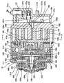
図2は膨張機一体型圧縮機10の断面図であり、膨張機一体型圧縮機10は、流体(本実施形態では、気相冷媒)を圧縮または膨張させるポンプモータ機構100、回転エネルギーが入力されることにより電気エネルギーを出力し、電力が入力されることにより回転エネルギーを出力する回転電機200、外部駆動源(駆動減)を成すエンジン20からの動力を断続可能にポンプモータ機構100側に伝達する動力伝達機構を成す電磁クラッチ300、並びにポンプモータ機構100、回転電機200および電磁クラッチ300間における動力伝達経路を切替えると共に、その回転動力の回転数を減速又は増速して伝達する遊星歯車機構から成る変速機構400等から構成されている。
FIG. 2 is a cross-sectional view of the expander-integrated
ここで、回転電機200はステータ210およびステータ210内で回転するロータ220等から成るもので、ステータ210は巻き線が巻かれたステータコイルであり、ロータ220は永久磁石が埋設されたマグネットロータである。
Here, the rotating
そして、本実施形態では、回転電機200は、ステータ210に電力が供給された場合にはロータ220を回転させてポンプモータ機構100を駆動する電動モータとして作動し、ロータ220を回転させるトルクが入力された場合には電力を発生させる発電機(本発明の回生機構に対応)として作動する。
In the present embodiment, the rotating
また、電磁クラッチ300は、Vベルトを介してエンジン20からの動力を受けるプーリ部310、磁界を発生させる励磁コイル320、および励磁コイル320により誘起された磁界により電磁力により変位するフリクションプレート330等から成るもので、エンジン20側と膨張機一体型圧縮機10側とを繋ぐときは励磁コイル320に通電し、エンジン20側と膨張機一体型圧縮機10側とを切り離すときは励磁コイル320への通電を遮断する。
The
また、ポンプモータ機構100は、周知のスクロール型圧縮機構とほぼ同一構造を有するもので、具体的には、ミドルハウジング101を介して回転電機200のステータハウジング230に対して固定された固定スクロール(固定スクロール部材、ハウジング)102、ミドルハウジング101と固定スクロール102との間の空間で旋回変位する可動部材を成す旋回スクロール(可動スクロール部材)103、および作動室Vと高圧室104とを連通させる連通路105、106を開閉する弁機構107等から成るものである。
The
ここで、固定スクロール102は、板状の基板部(第1基板部)102aおよび基板部102aから旋回スクロール103側に突出した渦巻状の歯部(第1歯部)102bを有して構成され、一方、旋回スクロール103は、歯部102bに接触して噛み合う渦巻状の歯部(第2歯部)103b、および歯部103bが形成された基板部(第2基板部)103aを有して構成されており、両歯部102b、103bが接触した状態で旋回スクロール103が旋回することにより、両スクロール102、103により構成された作動室Vの体積が拡大縮小する。
Here, the fixed
シャフト108は、一方の長手方向端部に回転中心軸に対して偏心した偏心部108aを有するクランクシャフトであり、この偏心部108aは、ブッシング103dおよびベアリング103c等を介して旋回スクロール103に連結されている。
The
尚、ブッシング103dは、偏心部108aに対して僅かに変位することができるものであり、旋回スクロール103に作用する圧縮反力により、両歯部102b、103bの接触圧力が増大する向きに旋回スクロール103を変位させる従動クランク機構を構成するものである。
The
また、自転防止機構109は、シャフト108が1回転する間に旋回スクロール103が偏心部108a周りに1回転するようにするものである。このためシャフト108が回転すると、旋回スクロール103は、自転せずにシャフト108の回転中心軸周りを公転旋回し、且つ、作動室Vは、旋回スクロール103の外径側から中心側に変位するほど、その体積が縮小するように変化する。因みに、本実施形態では、自転防止機構109としてピン−リング(ピン−ホール)式を採用している。
Further, the
また、連通路105は、ポンプモード時に最小体積となる作動室Vと高圧室104とを連通させて圧縮された冷媒を吐出する吐出ポートであり、連通路106はモータモード時に最小体積となる作動室Vと高圧室104とを連通させて高圧室104に導入された高温、高圧の冷媒、つまり過熱蒸気を作動室Vに導く流入ポートである。
The
連通路106は、連通路105に合流するように形成されており、連通路105の作動室V側開口部は、モータモード時に作動室Vへ冷媒を導入する導入口105aとなっている。導入口105aはポンプモード時に作動室Vから冷媒を導出する導出口として機能する。導入口105aの開口形態は、本発明の要部であり、後で詳述する。
The
また、高圧室104は連通路105(以下、吐出ポート105と呼ぶ)から吐出された冷媒の脈動を平滑化する吐出室の機能を有するものであり、この高圧室104には、加熱器30および放熱器11側に接続される高圧ポート110が設けられている。
The high-
尚、蒸発器14および第2バイパス回路33側に接続される低圧ポート111は、ステータハウジング230に設けられてステータハウジング230内を経由してステータハウジング230と固定スクロール102との間の空間に連通している。
The
また、吐出弁107aは、吐出ポート105の高圧室104側に配置されて吐出ポート105から吐出された冷媒が高圧室104から作動室Vに逆流することを防止するリード弁状の逆止弁であり、ストッパ107bは吐出弁107aの最大開度を規制する弁止板であり、吐出弁107aおよびストッパ107bはボルト107cにて基板部102aに固定されている。
The
スプール107dは、連通路106(以下、流入ポート106と呼ぶ)を開閉する弁体であり、電磁弁107eは低圧ポート111側と背圧室107fとの連通状態を制御することにより背圧室107f内の圧力を制御する制御弁であり、バネ107gは流入ポート106を閉じる向きの弾性力をスプール107dに作用させる弾性手段であり、絞り107hは所定の通路抵抗を有して背圧室107fと高圧室104とを連通させる抵抗手段である。
The
そして、電磁弁107eを開くと、背圧室107fの圧力が高圧室104より低下してスプール107dがバネ107gを押し縮めながら紙面右側に変位するので、流入ポート106が開く。尚、絞り107hでの圧力損失は非常に大きいので、高圧室104から背圧室107fに流れ込む冷媒量は無視できるほど小さい。
When the
逆に、電磁弁107eを閉じると、背圧室107fの圧力と高圧室104との圧力が等しくなるので、スプール107dはバネ107gの力により紙面左側に変位するので、流入ポート106が閉じる。つまり、スプール107d、電磁弁107e、背圧室107f、バネ107gおよび絞り107h等により流入ポート106を開閉するパイロット式の電気開閉弁が構成される。
Conversely, when the
また、変速機構400は、中心部に設けられたサンギヤ401と、サンギヤ401の外周で自転しつつ公転するピニオンギヤ402aに連結されるプラネタリーキャリヤ402と、ピニオンギヤ402aの更に外周に設けられたリング状のリングギヤ403とから成るものである。
Further, the
そして、サンギヤ401は、回転電機200のロータ220と一体化され、プラネタリーキャリヤ402は、電磁クラッチ300のフリクションプレート330と一体的に回転するシャフト331に一体化され、更に、リングギヤ403は、シャフト108の他方の長手方向端部(反偏心部側)に一体化されている。
The
また、ワンウェイクラッチ500は、シャフト331が一方向(プーリ部310の回転方向)にのみ回転することを許容するもので、軸受332はシャフト331を回転可能に支持するもので、軸受404はサンギヤ401、つまりロータ220をシャフト331に対して回転可能に支持するものであり、軸受405はシャフト331(プラネタリーキャリヤ402)をシャフト108に対して回転可能に支持するものであり、軸受108bはシャフト108をミドルハウジング101対して回転可能に支持するものである。
The one-
また、リップシール333は、シャフト331とステータハウジング230との隙間から冷媒がステータハウジング230外に漏れ出すことを防止する軸封装置である。
The
ここで、モータモード時に作動室Vへ冷媒を導入する導入口105aについて説明する。
Here, the
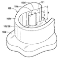
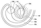
図4は、固定スクロール102の歯部102b先端部(渦巻状中心側先端部、所謂巻き始め部)を示す斜視図である。
FIG. 4 is a perspective view showing the distal end portion of the
図4に示すように、固定スクロール102の基板部102aを貫通するように形成された吐出ポート105(流入ポート106でもある)は、一部が歯部102b内に掘り込まれて歯部102b内に延設されており、前述した開口端である導入口105aは、基板部102aの歯部102b近傍に開口するとともに、基板部102aから歯部102bの歯丈方向(歯部の立設方向)に延びるように開口している。
As shown in FIG. 4, a discharge port 105 (also an inflow port 106) formed so as to penetrate through the
本実施形態のポンプモータ機構100では、固定スクロール102の歯部102bおよび旋回スクロール103の歯部103b(図1、図5参照)は、モータモード時に、歯部102b、103b相互がスクロール中心部において1つの当接面121で当接した後、作動室Vを形成するように立設配置されている。
In the
そして、歯部102bの歯丈方向に延設された導入口105aは、歯部102bにおいて、全域がこの当接面121となる領域(2本の一点鎖線で挟まれた領域)内に開口している。
The
また、導入口105aの歯部102bにおける歯丈方向の延設長さLは、歯部102bの高さHより小さくなっている。これにより、導入口105aの図中上方側には遮断壁102dが形成され、遮断壁102dが流入ポート106から導入口105aに向かう冷媒を遮断して、冷媒が歯部102b図中上面側(すなわち旋回スクロール基板側)に到達することを抑止するようになっている。
Further, the extending length L in the tooth height direction of the
次に、本実施形態に係る膨張機一体型圧縮機10の作動およびその作用効果について述べる。
Next, the operation and effects of the expander-integrated
1.ポンプモード(圧縮モード)
このモードは、シャフト108に回転力を与えることによりポンプモータ機構100の旋回スクロール103を旋回させて冷媒を吸入圧縮する運転モードである。
1. Pump mode (compression mode)
This mode is an operation mode in which the
具体的には、液ポンプ32を停止させた状態で開閉弁34を開き、三方弁21の切替えによって、エンジン冷却水を加熱器30側に循環させないようにする。また、電磁弁107eを閉じてスプール107dによって流入ポート106を閉じた状態でシャフト108を回転させるようにする。
Specifically, the on / off
これにより、膨張機一体型圧縮機10は、周知のスクロール型圧縮機と同様に、低圧ポート111から冷媒を吸引して、スクロール外周部から中心部に向かって移動する作動室Vにて圧縮した後、吐出ポート105から高圧室104に圧縮した冷媒を吐出し、高圧ポート110から圧縮された冷媒を放熱器11側に吐出する。
As a result, the expander-integrated
この時、シャフト108に回転力を与えるに当たっては、主に電磁クラッチ300にてエンジン20側と膨張機一体型圧縮機10側とを繋いでエンジン20の動力により回転力を与える場合と、電磁クラッチ300にてエンジン20側と膨張機一体型圧縮機10側とを切り離して回転電機200により回転力を与える場合とがある。
At this time, when the rotational force is applied to the
そして、電磁クラッチ300にてエンジン20側と膨張機一体型圧縮機10側とを繋いでエンジン20の動力により回転力を与える場合には、電磁クラッチ300に通電して電磁クラッチ300を繋ぐと共に、サンギヤ401、つまりロータ220が回転しない程度のトルクがロータ220に発生するように回転電機200に通電する。
And when connecting the
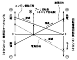
これにより、プーリ部310に伝達されたエンジン20の回転力は、変速機構400にて増速されてポンプモータ機構100に伝達され、ポンプモータ機構100を圧縮機として稼動させる(図3中のエンジン駆動圧縮)。
As a result, the rotational force of the
尚、電磁クラッチ300にてエンジン20側と膨張機一体型圧縮機10側とを切り離して回転電機200により回転力を与える場合には、電磁クラッチ300への通電を遮断して電磁クラッチ300を切った状態で回転電機200に通電して、プーリ部310の回転方向とは逆回転方向に作動させることで、ポンプモータ機構100を圧縮機として稼動させる。
When the
この時、シャフト331(プラネタリーキャリヤ402)は、ワンウェイクラッチ500によりロックされ回転しないので、回転電機200の回転力は、変速機構400にて減速されてポンプモータ機構100に伝達される(図3中の電動圧縮)。
At this time, since the shaft 331 (planetary carrier 402) is locked by the one-
そして、高圧ポート110から吐出される冷媒は、加熱器30→開閉弁34→放熱器11→気液分離器12→減圧器13→蒸発器14→逆止弁14a→膨張機一体型圧縮機10の低圧ポート111の順に循環(冷凍サイクルを循環)し、蒸発器14の吸熱による冷房(あるいは放熱器11の放熱による暖房)が行われる。尚、加熱器30にエンジン冷却水が循環しないので、加熱器30にて冷媒は加熱されず、加熱器30は単なる冷媒通路として機能する。
The refrigerant discharged from the high-
2.モータモード(膨張モード)
このモードは、高圧室104に加熱器30にて加熱された高圧の過熱蒸気冷媒をポンプモータ機構100に導入して膨張させることにより、旋回スクロール103を旋回させてシャフト108を回転させ、機械的出力を得るものである。
2. Motor mode (expansion mode)
In this mode, high-pressure superheated vapor refrigerant heated by the
尚、本実施形態では、得られた機械的出力によりロータ220を回転させて回転電機200により発電し、その発電された電力を蓄電器に蓄えるようにしている。
In the present embodiment, the
具体的には、開閉弁34を閉じた状態で液ポンプ32を稼動させ、三方弁21の切替えによって、エンジン冷却水を加熱器30側に循環させるようにする。また、膨張機一体型圧縮機10の電磁クラッチ300への通電を遮断して電磁クラッチ300を切った状態で電磁弁107eを開いてスプール107dによって流入ポート106を開き、高圧室104に加熱器30にて加熱された高圧の過熱蒸気冷媒を流入ポート106を経由させて作動室Vに導入して、スクロール中心部で形成され外周部に向かって移動する作動室V内において膨張させる。
Specifically, the
これにより、過熱蒸気の膨張により旋回スクロール103がポンプモード実行時の逆向きに回転するので、膨張を終えて圧力が低下した冷媒は、低圧ポート111から放熱器11側に流出すると共に、旋回スクロール103に与えられた回転エネルギーは、変速機構400にて増速されて回転電機200のロータ220に伝達される。
As a result, the
この時、シャフト331(プラネタリーキャリヤ402)は、ワンウェイクラッチ500によりロックされ回転しないので、旋回スクロール103の回転力は、変速機構400にて増速されて回転電気200に伝達される(図3中の膨張回生)。
At this time, since the shaft 331 (planetary carrier 402) is locked by the one-
そして、低圧ポート111から流出される冷媒は、第2バイパス回路33→逆止弁33a→放熱器11→気液分離器12→第1バイパス回路31→逆止弁31a→液ポンプ32→加熱器30→膨張機一体型圧縮機10(高圧ポート110)の順に循環することになる(ランキンサイクルを循環)。尚、液ポンプ32は、加熱器30にて加熱されて生成された過熱蒸気冷媒が気液分離器12側に逆流しない程度の圧力にて液相冷媒を加熱器30に送り込む。
And the refrigerant | coolant which flows out out of the low voltage |
ここで、モータモード時におけるスクロール中心部での作動室Vの形成と、この作動室Vへの冷媒の導入について説明する。 Here, formation of the working chamber V at the center of the scroll in the motor mode and introduction of the refrigerant into the working chamber V will be described.
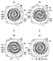
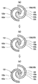
図5は、膨張機一体型圧縮機10の図2におけるA−A線断面図であり、図5(a)〜(d)で旋回スクロール103が公転運動を1回転(作動一周期)する状態を示している。
5 is a cross-sectional view of the expander-integrated
図5(a)に示すように、まず、固定スクロール102の歯部102bと、旋回スクロール103の歯部103bとは、歯部102b、103b相互がスクロール中心部において1つの当接面121で当接する。
As shown in FIG. 5A, first, the
次に、図5(b)に示すように、旋回スクロール103の歯部103bが移動し、図5(a)に示す当接面121が2つの摺接部122、123に移行するときに2つの摺接部122、123に間に作動室Vが形成される。このとき、高圧の過熱蒸気冷媒が導入口105aから作動室V内に導入される。
Next, as shown in FIG. 5 (b), the
導入口105aは、固定スクロール102の当接面121領域内に開口しているので、スクロール中心部において新しい作動室Vの形成が開始された時点(歯部102b、103b間の空間の旋回スクロール103公転軸方向投影面積が0から正値となった時点)から、作動室V内に導入口105aから冷媒が導入され、図5(c)、(d)に示すように摺接部122、123が移動して作動室Vが拡張するのに伴ない、中心部の作動室Vへの高圧冷媒の導入が継続される。
Since the
そして、旋回スクロール103が1回転し、図5(a)に示す状態に戻るときに、中心部において形成された作動室Vは、歯部102b、103b相互の当接部121により導入口105aを閉じられて冷媒導入が中止されるとともに、2つの作動室Vに分割されてスクロール外周部へ移動していく。
Then, when the
図5(a)に示す状態に戻った直後には、前述したように、当接面121が2つの摺接部122、123に移行するときに2つの摺接部122、123に間に新たな作動室Vが形成される。このとき、分割されてスクロール外周部へ移動していく先に形成された作動室Vと、新たに形成された作動室Vとは、摺接部122、123によりシールされている。
Immediately after returning to the state shown in FIG. 5A, as described above, when the
したがって、先に形成され冷媒が膨張している作動室V内に、新たに形成された作動室V内に導入されている高圧冷媒が漏れ難い。 Therefore, it is difficult for the high-pressure refrigerant introduced into the newly formed working chamber V to leak into the previously formed working chamber V in which the refrigerant is expanded.
また、歯部102b、103b相互が当接面121で当接して先に形成された作動室Vへの冷媒導入が中止された直後には、当接面121領域内に開口した導入口105aから、次に形成される新たな作動室V内への冷媒導入が開始される。したがって、順次形成される作動室Vへの冷媒の導入が途切れることがない。
Immediately after the introduction of the refrigerant into the previously formed working chamber V after the
このようにして、モータモード時に、高圧側からの漏れこみを抑えるシール性を確保しつつ、順次形成される作動室Vの切り替わりをスムースに行なうことができる。 In this way, in the motor mode, it is possible to smoothly switch the working chambers V that are sequentially formed while ensuring a sealing property that suppresses leakage from the high-pressure side.
ちなみに、従来、圧縮機として設計しこれを膨張機として作動した場合には、図7に示すように、導入口105bをなす圧縮モード時の吐出ポート105は、一般的に固定スクロール102の基板部102aに開口していた。
Incidentally, when the compressor is conventionally designed as a compressor and operated as an expander, as shown in FIG. 7, the
このような膨張機では、本実施形態と同様に旋回スクロール103が旋回したときであっても、図7(a)に示す歯部102b、103b相互が当接する前の状態から、図7(b)に示す当接状態を経て、図7(c)に示す歯部102b、103b間に空間が形成される状態に至る課程では、導入口105bは閉塞されて冷媒の導入が停止し、作動室Vの切り替えをスムースに行なうことはできない。
In such an expander, even when the
また、本実施形態では、固定スクロール102の歯部102bには、導入口105aより旋回スクロール103基板部103a側に遮断壁102dが設けられている。したがって、流入ポート106内の高圧冷媒が固定スクロール102の歯部102bと、旋回スクロール103の基板部103aとの間に到達し難く、高圧側からの漏れこみを抑えるシール性をさらに向上することができる。
In the present embodiment, the
また、本実施形態では、図5に示すように、固定スクロール102歯部102bの旋回スクロール103基板部103aとの摺接面(渦巻状端面)には、チップシール102cが設けられ、旋回スクロール103歯部103bの固定スクロール102基板部102aとの摺接面(渦巻状端面)には、チップシール103eが設けられ、各摺接箇所のシール性を高めている。
Further, in this embodiment, as shown in FIG. 5, a
従来、圧縮機として設計しこれを膨張機として作動する場合には、先にも述べ、図8にも示すように、導入口105bをなす圧縮モード時の吐出口105は、一般的に固定スクロール102の基板部102aに開口しており、歯部相互の当接面領域には設けられない。
Conventionally, when the compressor is designed and operated as an expander, the
そして、旋回スクロール103歯部103b(図7参照)にチップシール103eを設ける場合には、旋回スクロール103が旋回したときにチップシール103eの軌跡(図8に二点鎖線で示す作動一周期に渡る軌跡)が導入口105bに重なるとチップシール103eが折損する可能性があるため、チップシール103eを可動スクロール103歯部103bの先端にまで延設することはできなかった(図7参照)。ここで、図8は、固定スクロール102と旋回スクロール側のチップシール103eとの位置関係のみを示している。
When the
ところが、本実施形態では、導入口105aを歯部102bと歯部103bとの当接面121に設けることにより、図6に示すように、旋回スクロール側のチップシール103eは、旋回スクロール103が公転運動したときに導入口105aと重ならない領域内において(導入口105aを避けて)、歯部103bの中心部側先端近傍にまで延設することができる(図5参照)。
However, in this embodiment, by providing the
これにより、固定スクロール102の基板部102aと旋回スクロール103の歯部103bとの間のシール性を向上することができる。ここで、図6は、固定スクロール102と旋回スクロール側のチップシール103eとの位置関係のみを示している。
Thereby, the sealing performance between the board |
なお、本実施形態の説明において当接、摺接と表現した部位では、厳密な意味での接触が行なわれる場合に限らず、スクロールの旋回動作を容易にするために、僅かなクリアランスが形成されている場合も含んでいる。すなわち、厳密な意味での当接、摺接でなくても、当接面や摺接部は作動室を区画する(作動室間をシールして各作動室を機能させる)ものであればよい。僅かなクリアランスが形成されている場合も含む概略当接、概略摺接であっても、実質的な当接、摺接であると言える。 Note that in the description of the present embodiment, a portion expressed as contact or sliding contact is not limited to contact in a strict sense, and a slight clearance is formed in order to facilitate the scroll turning operation. It includes cases where In other words, even if the contact and sliding contact are not strictly defined, the contact surface and the sliding contact portion may be any one that partitions the working chambers (seals the working chambers to function each working chamber). . It can be said that the substantial contact and the sliding contact include substantial contact and sliding contact including a case where a slight clearance is formed.
(他の実施形態)
上記一実施形態では、導入口105aは、歯部102bの歯丈方向に延設されて、当接面121となる領域内に開口していたが、固定スクロール102の当接面121領域内に開口していれば、例えば基板部102aのみに開口(すなわち、当接面121領域の基板部102a側の辺部に開口)するものであってもよい。
(Other embodiments)
In the above-described embodiment, the
また、上記一実施形態では、膨張機一体型圧縮機10にて回収したエネルギーを蓄電器にて蓄えたが、フライホィールによる運動エネルギーまたはバネにより弾性エネルギー等の機械的エネルギーとして蓄えても良い。
Moreover, in the said one Embodiment, although the energy collect | recovered with the expander integrated
また、上記一実施形態では、変速機構400として遊星歯車機構を用いたが、本発明はこれに限定されるものではなく、例えばCVT(ベルト式無段変速機構)やベルトを用いないトロイダル方式の変速機構等の変速比を変更できる変速機構を用いても良い。また、変速機構を有しない膨張機一体型圧縮機に本発明を適用してもかまわない。
In the above-described embodiment, the planetary gear mechanism is used as the
また、ランキンサイクルを備える車両用蒸気圧縮式冷凍機に本発明に係る流体機械を適用したが、本発明の適用はこれに限定されるものではない。 Moreover, although the fluid machine which concerns on this invention was applied to the vapor compression refrigerator for vehicles provided with a Rankine cycle, application of this invention is not limited to this.
10 膨張機一体型圧縮機(流体機械)
100 ポンプモータ機構
102 固定スクロール(固定スクロール部材)
102a 基板部(第1基板部)
102b 歯部(第1歯部)
103 旋回スクロール(可動スクロール部材)
103a 基板部(第2基板部)
103b 歯部(第2歯部)
103e チップシール
105a 導入口
121 当接面(歯部102bと歯部103bとの当接面)
122、123 摺接部(歯部102bと歯部103bとの摺接部)
H 歯部102b歯丈方向高さ
L 導入口105a延設長さ
V 作動室
10 Expander-integrated compressor (fluid machine)
100
102a Substrate (first substrate)
102b Tooth part (first tooth part)
103 Orbiting scroll (movable scroll member)
103a Substrate part (second substrate part)
103b Tooth part (second tooth part)
122, 123 Sliding contact portion (sliding contact portion between
Claims (4)
渦巻状の第2歯部(103b)およびこの第2歯部(103b)を支持する第2基板部(103a)を有し、前記第2歯部(103b)形成側が前記固定スクロール部材(102)の前記第1歯部(102b)形成側と向かい合って配設され、自転を防止しつつ公転運動を行なう可動スクロール部材(103)と、
前記2つのスクロール部材(102、103)の間において、前記第1歯部(102b)と前記第2歯部(103b)との2つの摺接部(122、123)の間に設けられ、前記可動スクロール部材(103)の公転運動によって容積が変化する作動室(V)とを備え、
前記作動室(V)が前記固定スクロール部材(102)の外周部で順次形成され中心部に向かって移動しながら容積を縮小し、前記作動室(V)で流体を圧縮して吐出する圧縮モード、および、前記作動室(V)が前記固定スクロール部材(102)の中心部で順次形成され外周部に向かって移動しながら容積を増大し、前記作動室(V)で流体を膨張して吐出する膨張モードで運転することが可能な流体機械であって、
前記膨張モードで運転する場合には、前記中心部において前記第1歯部(102b)と前記第2歯部(103b)とが1つの当接面(121)で当接した後、この当接面(121)が前記2つの摺接部(122、123)に移行するときに前記2つの摺接部(122、123)の間に前記作動室(V)が形成され、
前記固定スクロール部材(102)は、前記当接面(121)となる領域に開口し、前記中心部で形成される前記作動室(V)に前記流体を導入するための導入口(105a)を備えることを特徴とする流体装置。 A fixed scroll member (102) having a spiral first tooth portion (102b) and a first substrate portion (102a) supporting the first tooth portion (102b);
It has a spiral second tooth portion (103b) and a second substrate portion (103a) that supports the second tooth portion (103b), and the side on which the second tooth portion (103b) is formed is the fixed scroll member (102). A movable scroll member (103) that is disposed to face the first tooth portion (102b) forming side and performs a revolving motion while preventing rotation,
Between the two scroll members (102, 103), provided between two sliding contact portions (122, 123) of the first tooth portion (102b) and the second tooth portion (103b), A working chamber (V) whose volume is changed by the revolving motion of the movable scroll member (103),
A compression mode in which the working chamber (V) is sequentially formed on the outer peripheral portion of the fixed scroll member (102), the volume is reduced while moving toward the center portion, and the fluid is compressed and discharged in the working chamber (V). The working chamber (V) is sequentially formed at the center of the fixed scroll member (102), and the volume is increased while moving toward the outer peripheral portion, and the fluid is expanded and discharged in the working chamber (V). A fluid machine capable of operating in an expansion mode,
When operating in the expansion mode, the first tooth portion (102b) and the second tooth portion (103b) are brought into contact with each other at one contact surface (121) in the central portion, and then the contact is made. When the surface (121) moves to the two sliding contact portions (122, 123), the working chamber (V) is formed between the two sliding contact portions (122, 123),
The fixed scroll member (102) has an inlet (105a) for opening the fluid into the working chamber (V) formed in the central portion, opening in a region to be the contact surface (121). A fluidic device comprising:
前記チップシール(103e)は、前記可動スクロール部材(103)が公転運動したときに前記導入口(105a)と重ならない領域内において、前記第2歯部(103b)の前記中心部側先端近傍にまで延設されていることを特徴とする請求項1ないし請求項3のいずれか1つに記載の流体機械。 The second tooth portion (103b) includes a tip seal (103e) extending in a spiral direction of the second tooth portion (103b) on a sliding contact surface with the first substrate portion (102a),
The tip seal (103e) is located near the front end of the second tooth portion (103b) on the center side in a region where the movable scroll member (103) does not overlap with the introduction port (105a) when the orbiting scroll member (103) revolves. The fluid machine according to any one of claims 1 to 3, wherein the fluid machine is extended to a distance.
Priority Applications (4)
| Application Number | Priority Date | Filing Date | Title |
|---|---|---|---|
| JP2004104817A JP2005291037A (en) | 2004-03-31 | 2004-03-31 | Fluid machine |
| DE102005013510A DE102005013510A1 (en) | 2004-03-31 | 2005-03-23 | fluid machine |
| US11/091,421 US7344364B2 (en) | 2004-03-31 | 2005-03-29 | Fluid machine |
| CNA2005100629391A CN1676882A (en) | 2004-03-31 | 2005-03-31 | Fluid machine |
Applications Claiming Priority (1)
| Application Number | Priority Date | Filing Date | Title |
|---|---|---|---|
| JP2004104817A JP2005291037A (en) | 2004-03-31 | 2004-03-31 | Fluid machine |
Publications (1)
| Publication Number | Publication Date |
|---|---|
| JP2005291037A true JP2005291037A (en) | 2005-10-20 |
Family
ID=35049592
Family Applications (1)
| Application Number | Title | Priority Date | Filing Date |
|---|---|---|---|
| JP2004104817A Pending JP2005291037A (en) | 2004-03-31 | 2004-03-31 | Fluid machine |
Country Status (4)
| Country | Link |
|---|---|
| US (1) | US7344364B2 (en) |
| JP (1) | JP2005291037A (en) |
| CN (1) | CN1676882A (en) |
| DE (1) | DE102005013510A1 (en) |
Families Citing this family (10)
| Publication number | Priority date | Publication date | Assignee | Title |
|---|---|---|---|---|
| JP2006242133A (en) * | 2005-03-04 | 2006-09-14 | Denso Corp | Fluid machine |
| US7841845B2 (en) * | 2005-05-16 | 2010-11-30 | Emerson Climate Technologies, Inc. | Open drive scroll machine |
| JP4884904B2 (en) * | 2006-09-26 | 2012-02-29 | 三菱重工業株式会社 | Fluid machinery |
| JP5001928B2 (en) * | 2008-10-20 | 2012-08-15 | サンデン株式会社 | Waste heat recovery system for internal combustion engines |
| US10215451B2 (en) * | 2014-05-12 | 2019-02-26 | Panasonic Intellectual Property Management Co., Ltd. | Compressor and refrigeration cycle device using same |
| US10077922B2 (en) * | 2014-05-12 | 2018-09-18 | Panasonic Intellectual Property Management Co., Ltd. | Compressor and refrigeration cycle device using same |
| KR102497530B1 (en) | 2018-05-28 | 2023-02-08 | 엘지전자 주식회사 | Scroll compressor having enhanced discharge structure |
| CN110822050B (en) * | 2019-11-26 | 2021-08-31 | 奇瑞汽车股份有限公司 | Power transmission system |
| US11952961B2 (en) * | 2020-11-16 | 2024-04-09 | L. Doug Sheneman | Energy pump |
| WO2024248672A1 (en) * | 2023-05-28 | 2024-12-05 | Михаил Алексеевич ИГНАТОВ | Geothermal electric generator |
Family Cites Families (8)
| Publication number | Priority date | Publication date | Assignee | Title |
|---|---|---|---|---|
| JPS6041237B2 (en) * | 1981-03-09 | 1985-09-14 | サンデン株式会社 | Scroll type fluid device |
| JP2540738B2 (en) | 1986-10-13 | 1996-10-09 | 日本電装株式会社 | Exhaust heat utilization device for vehicle mounting |
| US5242283A (en) * | 1991-03-15 | 1993-09-07 | Kabushiki Kaisha Toyoda Jidoshokki Seisakusho | Scroll type compressor with elongated discharge port |
| JPH051882U (en) * | 1991-06-27 | 1993-01-14 | 株式会社豊田自動織機製作所 | Scroll compressor |
| JP2884883B2 (en) * | 1992-02-21 | 1999-04-19 | 株式会社豊田自動織機製作所 | Refrigerant gas discharge structure in scroll compressor |
| JP3696955B2 (en) | 1995-12-04 | 2005-09-21 | 三菱重工業株式会社 | Scroll fluid machinery |
| CN1082146C (en) | 1995-08-31 | 2002-04-03 | 三菱重工业株式会社 | Eddy tube type fluid machinery |
| JP3192939B2 (en) | 1995-08-31 | 2001-07-30 | 三菱重工業株式会社 | Scroll type fluid machine |
-
2004
- 2004-03-31 JP JP2004104817A patent/JP2005291037A/en active Pending
-
2005
- 2005-03-23 DE DE102005013510A patent/DE102005013510A1/en not_active Withdrawn
- 2005-03-29 US US11/091,421 patent/US7344364B2/en not_active Expired - Fee Related
- 2005-03-31 CN CNA2005100629391A patent/CN1676882A/en active Pending
Also Published As
| Publication number | Publication date |
|---|---|
| US7344364B2 (en) | 2008-03-18 |
| CN1676882A (en) | 2005-10-05 |
| DE102005013510A1 (en) | 2005-11-03 |
| US20050220646A1 (en) | 2005-10-06 |
Similar Documents
| Publication | Publication Date | Title |
|---|---|---|
| JP4722493B2 (en) | Fluid machinery | |
| JP4039320B2 (en) | Fluid machinery | |
| JP4493531B2 (en) | Fluid pump with expander and Rankine cycle using the same | |
| JP4034291B2 (en) | Fluid machinery | |
| JP4549941B2 (en) | Complex fluid machinery | |
| JP2005248809A (en) | Fluid machine | |
| JP4606840B2 (en) | Composite fluid machine and refrigeration apparatus using the same | |
| JP2005291037A (en) | Fluid machine | |
| JP2006242133A (en) | Fluid machine | |
| JP4078994B2 (en) | Fluid machinery and waste heat recovery system | |
| JP4070740B2 (en) | Switching valve structure for fluid machinery | |
| JP4111901B2 (en) | Fluid machinery | |
| JP4736813B2 (en) | Vehicle exhaust heat recovery system | |
| JP4463660B2 (en) | Refrigeration equipment | |
| JP5247734B2 (en) | Waste heat regeneration system | |
| CN100404790C (en) | fluid machinery | |
| JP2006342793A (en) | Fluid machine | |
| JP4549884B2 (en) | Fluid machinery | |
| JP2005090447A (en) | Fluid machine | |
| JP2006242049A (en) | Fluid machine and start control device for internal combustion engine using the same | |
| JP2008157152A (en) | Rankine cycle | |
| JP4055724B2 (en) | Fluid machinery | |
| JP2005313878A (en) | Rankine cycle system and control method for the same | |
| JP5484604B2 (en) | Refrigeration air conditioner |
Legal Events
| Date | Code | Title | Description |
|---|---|---|---|
| A621 | Written request for application examination |
Free format text: JAPANESE INTERMEDIATE CODE: A621 Effective date: 20060605 |
|
| A131 | Notification of reasons for refusal |
Free format text: JAPANESE INTERMEDIATE CODE: A131 Effective date: 20090203 |
|
| A02 | Decision of refusal |
Free format text: JAPANESE INTERMEDIATE CODE: A02 Effective date: 20090609 |