US11428229B2 - Scroll compressor having enhanced discharge structure - Google Patents
Scroll compressor having enhanced discharge structure Download PDFInfo
- Publication number
- US11428229B2 US11428229B2 US16/423,775 US201916423775A US11428229B2 US 11428229 B2 US11428229 B2 US 11428229B2 US 201916423775 A US201916423775 A US 201916423775A US 11428229 B2 US11428229 B2 US 11428229B2
- Authority
- US
- United States
- Prior art keywords
- discharge
- discharge hole
- orbiting
- end plate
- compressor
- Prior art date
- Legal status (The legal status is an assumption and is not a legal conclusion. Google has not performed a legal analysis and makes no representation as to the accuracy of the status listed.)
- Active, expires
Links
Images


Classifications
-
- F—MECHANICAL ENGINEERING; LIGHTING; HEATING; WEAPONS; BLASTING
- F04—POSITIVE - DISPLACEMENT MACHINES FOR LIQUIDS; PUMPS FOR LIQUIDS OR ELASTIC FLUIDS
- F04C—ROTARY-PISTON, OR OSCILLATING-PISTON, POSITIVE-DISPLACEMENT MACHINES FOR LIQUIDS; ROTARY-PISTON, OR OSCILLATING-PISTON, POSITIVE-DISPLACEMENT PUMPS
- F04C18/00—Rotary-piston pumps specially adapted for elastic fluids
- F04C18/02—Rotary-piston pumps specially adapted for elastic fluids of arcuate-engagement type, i.e. with circular translatory movement of co-operating members, each member having the same number of teeth or tooth-equivalents
- F04C18/0207—Rotary-piston pumps specially adapted for elastic fluids of arcuate-engagement type, i.e. with circular translatory movement of co-operating members, each member having the same number of teeth or tooth-equivalents both members having co-operating elements in spiral form
- F04C18/0215—Rotary-piston pumps specially adapted for elastic fluids of arcuate-engagement type, i.e. with circular translatory movement of co-operating members, each member having the same number of teeth or tooth-equivalents both members having co-operating elements in spiral form where only one member is moving
-
- F—MECHANICAL ENGINEERING; LIGHTING; HEATING; WEAPONS; BLASTING
- F04—POSITIVE - DISPLACEMENT MACHINES FOR LIQUIDS; PUMPS FOR LIQUIDS OR ELASTIC FLUIDS
- F04C—ROTARY-PISTON, OR OSCILLATING-PISTON, POSITIVE-DISPLACEMENT MACHINES FOR LIQUIDS; ROTARY-PISTON, OR OSCILLATING-PISTON, POSITIVE-DISPLACEMENT PUMPS
- F04C29/00—Component parts, details or accessories of pumps or pumping installations, not provided for in groups F04C18/00 - F04C28/00
- F04C29/12—Arrangements for admission or discharge of the working fluid, e.g. constructional features of the inlet or outlet
- F04C29/124—Arrangements for admission or discharge of the working fluid, e.g. constructional features of the inlet or outlet with inlet and outlet valves specially adapted for rotary or oscillating piston pumps
- F04C29/126—Arrangements for admission or discharge of the working fluid, e.g. constructional features of the inlet or outlet with inlet and outlet valves specially adapted for rotary or oscillating piston pumps of the non-return type
- F04C29/128—Arrangements for admission or discharge of the working fluid, e.g. constructional features of the inlet or outlet with inlet and outlet valves specially adapted for rotary or oscillating piston pumps of the non-return type of the elastic type, e.g. reed valves
-
- F—MECHANICAL ENGINEERING; LIGHTING; HEATING; WEAPONS; BLASTING
- F04—POSITIVE - DISPLACEMENT MACHINES FOR LIQUIDS; PUMPS FOR LIQUIDS OR ELASTIC FLUIDS
- F04C—ROTARY-PISTON, OR OSCILLATING-PISTON, POSITIVE-DISPLACEMENT MACHINES FOR LIQUIDS; ROTARY-PISTON, OR OSCILLATING-PISTON, POSITIVE-DISPLACEMENT PUMPS
- F04C18/00—Rotary-piston pumps specially adapted for elastic fluids
- F04C18/02—Rotary-piston pumps specially adapted for elastic fluids of arcuate-engagement type, i.e. with circular translatory movement of co-operating members, each member having the same number of teeth or tooth-equivalents
- F04C18/0207—Rotary-piston pumps specially adapted for elastic fluids of arcuate-engagement type, i.e. with circular translatory movement of co-operating members, each member having the same number of teeth or tooth-equivalents both members having co-operating elements in spiral form
- F04C18/0246—Details concerning the involute wraps or their base, e.g. geometry
- F04C18/0253—Details concerning the base
- F04C18/0261—Details of the ports, e.g. location, number, geometry
-
- F—MECHANICAL ENGINEERING; LIGHTING; HEATING; WEAPONS; BLASTING
- F04—POSITIVE - DISPLACEMENT MACHINES FOR LIQUIDS; PUMPS FOR LIQUIDS OR ELASTIC FLUIDS
- F04C—ROTARY-PISTON, OR OSCILLATING-PISTON, POSITIVE-DISPLACEMENT MACHINES FOR LIQUIDS; ROTARY-PISTON, OR OSCILLATING-PISTON, POSITIVE-DISPLACEMENT PUMPS
- F04C18/00—Rotary-piston pumps specially adapted for elastic fluids
- F04C18/02—Rotary-piston pumps specially adapted for elastic fluids of arcuate-engagement type, i.e. with circular translatory movement of co-operating members, each member having the same number of teeth or tooth-equivalents
- F04C18/0207—Rotary-piston pumps specially adapted for elastic fluids of arcuate-engagement type, i.e. with circular translatory movement of co-operating members, each member having the same number of teeth or tooth-equivalents both members having co-operating elements in spiral form
- F04C18/0246—Details concerning the involute wraps or their base, e.g. geometry
- F04C18/0269—Details concerning the involute wraps
- F04C18/0292—Ports or channels located in the wrap
-
- F—MECHANICAL ENGINEERING; LIGHTING; HEATING; WEAPONS; BLASTING
- F04—POSITIVE - DISPLACEMENT MACHINES FOR LIQUIDS; PUMPS FOR LIQUIDS OR ELASTIC FLUIDS
- F04C—ROTARY-PISTON, OR OSCILLATING-PISTON, POSITIVE-DISPLACEMENT MACHINES FOR LIQUIDS; ROTARY-PISTON, OR OSCILLATING-PISTON, POSITIVE-DISPLACEMENT PUMPS
- F04C23/00—Combinations of two or more pumps, each being of rotary-piston or oscillating-piston type, specially adapted for elastic fluids; Pumping installations specially adapted for elastic fluids; Multi-stage pumps specially adapted for elastic fluids
- F04C23/008—Hermetic pumps
-
- F—MECHANICAL ENGINEERING; LIGHTING; HEATING; WEAPONS; BLASTING
- F04—POSITIVE - DISPLACEMENT MACHINES FOR LIQUIDS; PUMPS FOR LIQUIDS OR ELASTIC FLUIDS
- F04C—ROTARY-PISTON, OR OSCILLATING-PISTON, POSITIVE-DISPLACEMENT MACHINES FOR LIQUIDS; ROTARY-PISTON, OR OSCILLATING-PISTON, POSITIVE-DISPLACEMENT PUMPS
- F04C23/00—Combinations of two or more pumps, each being of rotary-piston or oscillating-piston type, specially adapted for elastic fluids; Pumping installations specially adapted for elastic fluids; Multi-stage pumps specially adapted for elastic fluids
- F04C23/02—Pumps characterised by combination with or adaptation to specific driving engines or motors
-
- F—MECHANICAL ENGINEERING; LIGHTING; HEATING; WEAPONS; BLASTING
- F04—POSITIVE - DISPLACEMENT MACHINES FOR LIQUIDS; PUMPS FOR LIQUIDS OR ELASTIC FLUIDS
- F04C—ROTARY-PISTON, OR OSCILLATING-PISTON, POSITIVE-DISPLACEMENT MACHINES FOR LIQUIDS; ROTARY-PISTON, OR OSCILLATING-PISTON, POSITIVE-DISPLACEMENT PUMPS
- F04C29/00—Component parts, details or accessories of pumps or pumping installations, not provided for in groups F04C18/00 - F04C28/00
- F04C29/04—Heating; Cooling; Heat insulation
- F04C29/042—Heating; Cooling; Heat insulation by injecting a fluid
-
- F—MECHANICAL ENGINEERING; LIGHTING; HEATING; WEAPONS; BLASTING
- F04—POSITIVE - DISPLACEMENT MACHINES FOR LIQUIDS; PUMPS FOR LIQUIDS OR ELASTIC FLUIDS
- F04C—ROTARY-PISTON, OR OSCILLATING-PISTON, POSITIVE-DISPLACEMENT MACHINES FOR LIQUIDS; ROTARY-PISTON, OR OSCILLATING-PISTON, POSITIVE-DISPLACEMENT PUMPS
- F04C29/00—Component parts, details or accessories of pumps or pumping installations, not provided for in groups F04C18/00 - F04C28/00
- F04C29/12—Arrangements for admission or discharge of the working fluid, e.g. constructional features of the inlet or outlet
-
- F—MECHANICAL ENGINEERING; LIGHTING; HEATING; WEAPONS; BLASTING
- F04—POSITIVE - DISPLACEMENT MACHINES FOR LIQUIDS; PUMPS FOR LIQUIDS OR ELASTIC FLUIDS
- F04C—ROTARY-PISTON, OR OSCILLATING-PISTON, POSITIVE-DISPLACEMENT MACHINES FOR LIQUIDS; ROTARY-PISTON, OR OSCILLATING-PISTON, POSITIVE-DISPLACEMENT PUMPS
- F04C2210/00—Fluid
- F04C2210/26—Refrigerants with particular properties, e.g. HFC-134a
-
- F—MECHANICAL ENGINEERING; LIGHTING; HEATING; WEAPONS; BLASTING
- F04—POSITIVE - DISPLACEMENT MACHINES FOR LIQUIDS; PUMPS FOR LIQUIDS OR ELASTIC FLUIDS
- F04C—ROTARY-PISTON, OR OSCILLATING-PISTON, POSITIVE-DISPLACEMENT MACHINES FOR LIQUIDS; ROTARY-PISTON, OR OSCILLATING-PISTON, POSITIVE-DISPLACEMENT PUMPS
- F04C2240/00—Components
- F04C2240/10—Stators
-
- F—MECHANICAL ENGINEERING; LIGHTING; HEATING; WEAPONS; BLASTING
- F04—POSITIVE - DISPLACEMENT MACHINES FOR LIQUIDS; PUMPS FOR LIQUIDS OR ELASTIC FLUIDS
- F04C—ROTARY-PISTON, OR OSCILLATING-PISTON, POSITIVE-DISPLACEMENT MACHINES FOR LIQUIDS; ROTARY-PISTON, OR OSCILLATING-PISTON, POSITIVE-DISPLACEMENT PUMPS
- F04C2240/00—Components
- F04C2240/20—Rotors
-
- F—MECHANICAL ENGINEERING; LIGHTING; HEATING; WEAPONS; BLASTING
- F04—POSITIVE - DISPLACEMENT MACHINES FOR LIQUIDS; PUMPS FOR LIQUIDS OR ELASTIC FLUIDS
- F04C—ROTARY-PISTON, OR OSCILLATING-PISTON, POSITIVE-DISPLACEMENT MACHINES FOR LIQUIDS; ROTARY-PISTON, OR OSCILLATING-PISTON, POSITIVE-DISPLACEMENT PUMPS
- F04C2240/00—Components
- F04C2240/30—Casings or housings
-
- F—MECHANICAL ENGINEERING; LIGHTING; HEATING; WEAPONS; BLASTING
- F04—POSITIVE - DISPLACEMENT MACHINES FOR LIQUIDS; PUMPS FOR LIQUIDS OR ELASTIC FLUIDS
- F04C—ROTARY-PISTON, OR OSCILLATING-PISTON, POSITIVE-DISPLACEMENT MACHINES FOR LIQUIDS; ROTARY-PISTON, OR OSCILLATING-PISTON, POSITIVE-DISPLACEMENT PUMPS
- F04C2240/00—Components
- F04C2240/40—Electric motor
-
- F—MECHANICAL ENGINEERING; LIGHTING; HEATING; WEAPONS; BLASTING
- F04—POSITIVE - DISPLACEMENT MACHINES FOR LIQUIDS; PUMPS FOR LIQUIDS OR ELASTIC FLUIDS
- F04C—ROTARY-PISTON, OR OSCILLATING-PISTON, POSITIVE-DISPLACEMENT MACHINES FOR LIQUIDS; ROTARY-PISTON, OR OSCILLATING-PISTON, POSITIVE-DISPLACEMENT PUMPS
- F04C29/00—Component parts, details or accessories of pumps or pumping installations, not provided for in groups F04C18/00 - F04C28/00
- F04C29/02—Lubrication; Lubricant separation
Definitions
- the present invention relates to a scroll compressor, and more particularly, to a scroll compressor having an enhanced discharge structure to discharge a refrigerant compressed in a compression chamber.
- a compressor is an apparatus configured to convert mechanical energy into compression energy of a compressible fluid.
- the compressor may be categorized into a reciprocating compressor, a rotary compressor, a vane compressor, and a scroll compressor in accordance with a method of compressing a fluid.
- the scroll compressor includes a fixed scroll having a fixed wrap and an orbiting scroll having an orbiting wrap engaged with the fixed wrap.
- the scroll compressor allows the orbiting scroll to perform an orbiting movement on the fixed scroll.
- the scroll compressor is provided with a compression chamber formed between the fixed wrap and the orbiting wrap in accordance with the orbiting movement of the orbiting scroll.
- the compression chamber formed between the fixed wrap and the orbiting wrap performs suction and compression of a refrigerant using a continuous volume change.
- the scroll compressor has an advantage capable of obtaining a relatively high compression ratio compared to other types of compressors. Also, the scroll compressor has an advantage capable of obtaining a stable torque because suction, compression, and discharge strokes of a refrigerant are smoothly performed.
- Characteristics of the scroll compressor are determined by shapes of the fixed wrap and the orbiting wrap. Although the fixed wrap and the orbiting wrap may have random shapes, the fixed wrap and the orbiting wrap generally have a form of an involute curve which is easy to process.
- the orbiting scroll generally has an orbiting end plate formed in a circular plate shape and the orbiting wrap formed at one side of the orbiting end plate.
- the scroll compressor includes a discharge hole configured to discharge a refrigerant compressed in each compression chamber.
- the refrigerant compressed in the compression chamber is discharged through the discharge hole, however, there is a problem in that it is difficult to make sure of a discharge area of the discharge hole at an initial discharge stage because the discharge hole is covered by the orbiting wrap. If the discharge area is not obtained sufficiently, discharge resistance becomes greater, whereby a smooth discharge is not performed.
- Patent Reference 1 Korean Patent Registration No. 10-1059880 (laid-open date: Aug. 29, 2011)
- the present invention is directed to a scroll compressor having an enhanced discharge structure that substantially obviates one or more problems due to limitations and disadvantages of the related art.
- An object of the present invention is to provide a scroll compressor having an enhanced discharge structure capable of making sure of a sufficient discharge area at an initial discharge stage to reduce a discharge resistance at an initial discharge stage.
- Another object of the present invention is to provide an auxiliary discharge path structure capable of making sure of a discharge area while maintaining a compression ratio of a scroll compressor.
- Another object of the present invention is to provide a scroll compressor that reduces a problem that an orbiting scroll is subjected to seizure with a fixed scroll.
- a compressor according to the present invention comprises an auxiliary discharge path capable of sufficiently making sure of a discharge area at an initial discharge stage.
- the compressor according to the present invention comprises a fixed scroll including a fixed end plate portion and a fixed wrap, and an orbiting scroll including an orbiting end plate portion and an orbiting wrap, wherein a discharge hole is formed in the fixed end plate portion, and an auxiliary discharge path for connecting a side of the orbiting wrap with a bottom surface of the orbiting wrap is provided to be communicated with the discharge hole, whereby a compressed refrigerant may be discharged through the auxiliary discharge path.
- the compressor according to the present invention provides a structure of an auxiliary discharge path to make sure of a discharge area while maintaining a compression ratio.
- the auxiliary discharge path provides a structure in which an inlet formed at a side of the orbiting wrap is arranged inside a side area of the orbiting wrap that forms a compression chamber at a discharge starting time.
- the compressor of the present invention provides a structure in which an orbiting scroll may be prevented from being subjected to seizure with a fixed scroll.
- the compressor according to the present invention provides a structure in which an auxiliary discharge path is formed on a bottom surface of the orbiting wrap having a friction with the fixed end plate portion in a recessed groove shape.
- the compressor according to the present invention provides a structure in which an auxiliary discharge path is provided at a center portion of an orbiting wrap to discharge a compressed refrigerant through the auxiliary discharge path.
- This structure results in an attenuation effect of discharge loss by enlarging an area to which the compressed refrigerant can be discharged.
- the compressor according to the present invention comprises an auxiliary discharge path connected from a side of an orbiting wrap to a bottom surface of the orbiting wrap, wherein an inlet of the auxiliary discharge path, which is formed at a side, is arranged inside a compression chamber area at a discharge starting time, whereby a discharge area may be enlarged without a change of a compression ratio.
- the compressor according to the present invention comprises an auxiliary discharge path formed on a bottom surface of an orbiting wrap, whereby a fixed end plate portion may be cooled by a refrigerant passing through the auxiliary discharge path.
- the auxiliary discharge path results in reducing a friction area by reducing a sectional area of the bottom surface of the orbiting wrap in which seizure occurs.
- FIG. 1 is a sectional view illustrating an entire structure of a scroll compressor according to the present invention
- FIG. 2 is an enlarged view illustrating a compression portion of a compressor according to the present invention
- FIG. 3 is a partially exploded perspective view illustrating a compression portion shown in FIG. 1 ;
- FIG. 4 is a perspective view respectively illustrating an orbiting scroll and a fixed scroll shown in FIG. 1 ;
- FIG. 5 is a partially exploded perspective view illustrating an orbiting scroll according to the first embodiment of the present invention.
- FIG. 6 is a partially exploded perspective view illustrating an orbiting scroll according to the second embodiment of the present invention.
- FIG. 7 is a view illustrating positions of a discharge hole and an auxiliary discharge path at a discharge starting time of a compressor according to the first embodiment of the present invention
- FIG. 9 is a view illustrating a state that a crank angle is rotated by addition of 20° at a discharge starting time in FIG. 7 ;
- FIG. 10 is a view illustrating a state that a crank angle is rotated by addition of 30° at a discharge starting time in FIG. 7 ;
- FIG. 11 is a view illustrating a state that a crank angle is rotated by addition of 40° at a discharge starting time in FIG. 7 ;
- FIG. 12 is a graph illustrating a change of an open area of a discharge inlet according to a change of a crank angle of a compressor which is not provided with an auxiliary discharge path;
- FIG. 13 is a graph illustrating a change of a flow velocity of a refrigerant according to a change of a crank angle of a compressor which is not provided with an auxiliary discharge path;
- FIG. 15 is a graph illustrating a change of a flow velocity of a refrigerant according to a change of a crank angle of a compressor which is provided with an auxiliary discharge path in accordance with the first embodiment of the present invention.
- FIG. 1 is a sectional view illustrating an entire structure of a scroll compressor according to the present invention.
- the scroll compressor to the embodiment of the present invention comprises a casing 110 forming a sealed inner space, a driving motor 120 arranged at an upper portion of the inner space, and a compression portion C performing suction and compression of a refrigerant in accordance with a rotational force of the driving motor.
- the casing 110 includes a cylindrical shell 111 of a cylindrical shape, a first shell coupled to an upper portion of the cylindrical shell 111 , and a second shell 113 coupled to a lower portion of the cylindrical shell 111 .
- first shell 112 is arranged at the upper portion and the second shell 113 is arranged at the lower portion, the first shell 112 may correspond to an upper shell, and the second shell 113 may correspond to a lower shell.
- a refrigerant suction pipe 116 and a refrigerant discharge portion 118 are coupled to the casing 110 .
- a refrigerant is sucked into the compressor 100 through the refrigerant suction pipe 116 .
- the sucked refrigerant is compressed in the compression portion C and then discharged from the compressor 100 through the refrigerant discharge portion 118 .
- the refrigerant suction pipe 116 may directly be connected to the compression portion C by passing through the cylindrical shell 111 .
- the refrigerant discharge portion 118 may be provided in the compressor 100 in a shape passing through the first shell 112 .
- the driving motor 120 includes a stator 122 , a rotor 124 , and a rotary shaft 126 .
- the rotary shaft 126 is coupled to the rotor in a single body. Also, the rotary shaft 126 is arranged to pass through the compression portion. The rotary shaft serves to transfer a rotational power to the compression portion.
- the compression portion C includes a main frame 130 , a fixed scroll 140 , an orbiting scroll 150 , an Oldham ring 160 , and a discharge cover 170 .
- the main frame 130 forms a portion of external appearance of the compression portion C. If the refrigerant discharge portion 118 is arranged toward the upper portion, the main frame 130 may correspond to the upper portion of the compression portion C.
- An outer circumference of the main frame 130 is coupled to an inner circumference of the casing.
- the main frame 130 serves to support the rotary shaft 126 that passes through the main frame 130 .
- the main frame 130 maintains a fixed state without being rotated with the rotary shaft 126 .
- the fixed scroll 140 may be arranged in the main frame 130 to be far away from the refrigerant discharge portion 118 .
- the fixed scroll 140 may be arranged at a lower portion of the main frame 130 .
- An outer circumference of the fixed scroll 140 is coupled to the inner circumference of the casing 110 .
- the fixed scroll 140 serves to support the rotary shaft 126 that passes through the fixed scroll 140 .
- the fixed scroll 140 maintains a fixed state without being rotated with the rotary shaft 126 .
- the fixed scroll 140 includes a discharge hole 148 through which a compressed refrigerant is discharged.
- a discharge valve 149 is arranged in the discharge hole 148 .
- the discharge valve 149 has a structure which is opened by a pressure of the refrigerant.
- the discharge valve 149 serves to allow the refrigerant which is opened and then compressed to be discharged from the compression chamber if the refrigerant which is discharged reaches a certain pressure.
- the orbiting scroll 150 may be arranged between the main frame 130 and the fixed scroll 140 .
- the orbiting scroll 150 may be received in the main frame 130 and the fixed scroll 140 .
- the orbiting scroll 150 is coupled to an eccentric portion 126 b of the rotary shaft 126 .
- the eccentric portion 126 b may be provided to be eccentric or protruded from the rotary shaft 126 in a diameter direction.
- the eccentric portion 126 b is eccentrically rotated by rotation of the rotary shaft 126 .
- the orbiting scroll 150 performs an orbiting movement by means of an eccentric rotation of the eccentric portion 126 b.
- the eccentric portion 126 b is rotatably coupled to the orbiting scroll 150 .
- the Oldham ring 160 is arranged between the orbiting scroll 150 and the main frame 130 .
- the Oldham ring 160 serves to allow the orbiting scroll 150 to perform an orbiting movement without performing rotation.
- the discharge cover 170 may be arranged in the fixed scroll 140 to be far away from the refrigerant discharge portion 118 .
- the discharge cover 170 may be arranged at the lower portion of the fixed scroll 140 .
- the discharge cover 170 may serve to separate the refrigerant and oil, which are discharged from the compression chamber, from each other.
- the oil circulates inside the compressor.
- the oil serves to improve tight sealing of the compression chamber, lubricate friction portions, and cool heat generated from the friction portions.
- the oil moves together with the refrigerant in a state that the oil is mixed with the refrigerant, or is stored by being separated from the refrigerant.
- the oil may be stored in one side of the casing 110 .
- the oil may be stored below the lower portion of the casing 110 .
- the oil may be stored in a lower space of the discharge cover 170 in the inner space of the casing.
- FIG. 2 is an enlarged view illustrating a compression portion of a compressor according to the present invention
- FIG. 3 is a partially exploded perspective view illustrating a compression portion shown in FIG. 1 .
- the compression portion includes a main frame 130 , a fixed scroll 140 , an orbiting scroll 150 , an Oldham ring 160 , and a discharge cover 170 .
- the fixed scroll 140 includes a fixed end plate portion 142 having a circular plate shape and a fixed wrap 144 formed to be protruded from the fixed end plate portion 142 .
- the discharge hole 148 is formed to pass through the fixed end plate portion 142 .
- a portion where the discharge hole 148 is connected with the compression chamber may be referred to as a discharge inlet.
- a portion where the discharge hole 148 is connected with the inside of the discharge cover 170 may be referred to as a discharge outlet.
- the discharge valve 149 is arranged at the discharge outlet.
- the orbiting scroll 150 includes an orbiting end plate portion 152 having a circular plate shape and an orbiting wrap 154 formed to be protruded from the orbiting end plate portion 152 .
- the orbiting end plate portion 152 may be arranged in parallel with the fixed end plate portion 142 .
- the orbiting wrap 154 may be formed to be protruded toward the fixed end plate portion 142 from one surface of the orbiting end plate portion 152 .
- One surface (or bottom surface) of the orbiting wrap 154 may be tightly adhered to the fixed end plate portion 142 .
- An exposed surface corresponding to a free end of the orbiting wrap 154 may be in contact with the fixed end plate portion 142 .
- the fixed wrap 144 may be formed to be protruded from one surface of the fixed end plate portion 142 .
- the fixed wrap 144 may be protruded toward the orbiting end plate portion 152 from the fixed end plate portion 142 .
- One surface of the fixed wrap 144 may be tightly adhered to the orbiting end plate portion 152 . That is, an exposed surface corresponding to a free end of the fixed wrap 144 may be tightly adhered to the orbiting end plate portion 152 .
- the orbiting wrap 154 may be engaged with the fixed wrap 144 to form a sealed space (hereinafter, referred to as compression chamber). If the orbiting wrap 154 performs an orbiting movement, the sealed space moves along a spiral track in a direction of the rotary shaft and its volume is reduced.
- a first compression chamber and a second compression chamber may be formed between the orbiting wrap and the fixed wrap.
- the first compression chamber may be formed between an inner surface of the fixed wrap and an outer surface of the orbiting wrap.
- the first compression chamber and the second compression chamber may move to the discharge hole after suction is completed with a phase difference.
- the first compression chamber and the second compression chamber may be combined with each other in a position close to the discharge hole. That is, the first compression chamber and the second compression chamber may be incorporated into one compression chamber at a position near the discharge hole.
- the fixed scroll 140 is provided with the discharge hole 148 in the fixed end plate portion 142 .
- the discharge inlet of the discharge hole 148 may be opened or closed in accordance with the orbiting movement of the orbiting wrap 154 .
- the discharge valve 149 is provided at the discharge outlet of the discharge hole 148 . Switching of the discharge valve 149 may be adjusted by a pressure of the refrigerant which is discharged.
- the refrigerant which is discharged through the discharge hole 148 may move to the discharge cover 170 and then pass through the driving motor 120 through the compression portion C. Afterwards, the refrigerant may be discharged to the outside of the compressor 100 through the refrigerant discharge portion 118 .
- FIG. 4 is a perspective view respectively illustrating an orbiting scroll and a fixed scroll shown in FIG. 1 .
- discharge holes 148 a and 148 b are formed in the fixed end plate portion 142 of the fixed scroll 140 .
- the discharge hole may include a plurality of discharge holes as shown.
- a discharge hole of a right side may be referred to as a first discharge hole 148 a
- another discharge hole may be referred to as a second discharge hole 148 b.
- the refrigerant compressed in the compression chamber is discharged to the outside of the compression chamber through the discharge holes 148 a and 148 b .
- Switching of the discharge holes 148 a and 148 b is adjusted by the bottom surface of the orbiting wrap 154 .
- the refrigerant is resisted when passing through the discharge holes 148 a and 148 b , and if a discharge area (area opened to move the refrigerant) of the discharge holes 148 a and 148 b is narrow, a flow velocity becomes fast, whereby discharge resistance is increased.
- the compression chamber formed between the orbiting wrap 154 and the fixed wrap 144 has a volume which is reduced in accordance with the orbiting movement of the orbiting scroll 150 , and moves to the center of the orbiting scroll.
- a bypass hole 147 is formed in the fixed end plate portion 142 .
- the bypass hole 147 is arranged on a moving path of the compression chamber.
- the bypass hole 147 provides a passage through which an overcompressed refrigerant is discharged.
- a portion where the bypass hole 147 is connected with the compression chamber may be referred to as an inlet, and its opposite portion may be referred to as an outlet.
- a bypass valve (not shown) is arranged at the outlet of the bypass hole 147 .
- Refrigerants of a liquid state may be mixed with each other and sucked into the compression chamber in accordance with an operation state of the compressor. If the refrigerants of the liquid state are mixed, their overcompression may be generated in the compression chamber.
- the bypass hole 147 provides a passage through which the overcompressed refrigerant is discharged.
- the refrigerant discharged through the bypass hole 147 moves to the inside of the discharge cover 170 in the same manner as the refrigerant discharged through the discharge holes 148 a and 148 b.
- the compressor of the related art provides a structure in which a compressed refrigerant is discharged through the discharge holes 148 a and 148 b formed in the fixed scroll 140 .
- This structure has a drawback in that discharge loss is increased due to a narrow discharge area of the discharge hole at the initial discharge stage.
- the compressor according to the present invention is characterized in that an auxiliary discharge path 156 is provided in the orbiting scroll 150 .
- the auxiliary discharge path 156 serves to allow the refrigerant compressed at a discharge starting time to be discharged to the discharge hole 148 a or 148 b by passing through the auxiliary discharge path 156 .
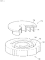
- FIG. 5 is a partially exploded perspective view illustrating an orbiting scroll according to the first embodiment of the present invention.
- the orbiting scroll 150 includes an orbiting end plate portion 152 having a circular plate shape, an orbiting wrap 154 formed to be protruded from the orbiting end plate portion 152 at a certain height, and an auxiliary discharge path 156 formed at a center portion of the orbiting wrap 154 in a groove shape which is recessed.
- the compressor according to the first embodiment of the present invention includes the auxiliary discharge path 156 at the center portion of the orbiting scroll.
- the auxiliary discharge path 156 is formed on the bottom of the orbiting wrap 154 in a recessed groove shape. Also, the auxiliary discharge path 156 is formed to partially remove a side of the orbiting wrap 154 , whereby an inlet 156 a is formed at the side of the orbiting wrap 154 .
- the auxiliary discharge path 156 may be provided in such a manner that the side of the orbiting wrap 154 is partially recessed. Therefore, the auxiliary discharge path 156 may form the inlet 156 a through which the refrigerant of the compression chamber enters one surface of the orbiting wrap 154 .
- the inlet 156 a of the auxiliary discharge path 156 is arranged inside a side area of the orbiting wrap, which forms the compression chamber at a discharge starting time.
- the inlet 156 a of the auxiliary discharge path 156 is to maintain a compression ratio by allowing the refrigerant not to move between the compression chambers therethrough.
- the inlet 156 a of the auxiliary discharge path 156 forms a wall of a single compression chamber until the discharge starts. If the inlet 156 a of the auxiliary discharge path 156 is formed over two compression chambers, compression efficiency may be deteriorated due to movement of the refrigerant between the two compression chambers.
- the auxiliary discharge path 156 may be provided such that its inlet faces the compression chamber provided near the discharge hole 148 .
- the auxiliary discharge path 156 may be provided such that its inlet is arranged to be far away from the rotary shaft 120 .
- the compressor according to the present invention does not give a change in a crank angle of the discharge starting time because the inlet 156 a of the auxiliary discharge path 156 formed in the orbiting wrap 154 is arranged inside the side area, which forms the compression chamber at the discharge starting time. Therefore, the compressor according to the present invention may increase a discharge area of the discharge hole without reducing the compression ratio.
- the auxiliary discharge path is formed on one surface (or bottom surface) of the center portion of the orbiting wrap in a recessed groove shape.
- the bottom surface close to the center portion of the orbiting wrap 154 is partially removed. That is, the auxiliary discharge path may be provided in such a manner that an exposed surface of the center portion of the orbiting wrap is recessed.
- the bottom surface of the center portion of the orbiting wrap is a portion tightly adhered to the fixed end plate portion 142 ( FIG. 4 ).
- the bottom surface of the center portion of the orbiting wrap 154 may be subjected to seizure with the fixed end plate portion 142 during operation of the compressor.
- a partial area of the bottom surface of the center portion of the orbiting wrap according to the present invention becomes the auxiliary discharge path 156 , an area of a portion subjected to seizure with the fixed end plate portion 142 may be reduced.
- the refrigerant moves through the auxiliary discharge path 156 , and the surface of the fixed end plate portion 142 may be cooled by the refrigerant which is moving, whereby seizure of the orbiting wrap may be more avoided. Also, since the oil moves together with the refrigerant, the oil may be supplied between one surface of the orbiting wrap and the fixed end plate portion.
- the auxiliary discharge path 156 has a groove shape from which a certain area is removed from one surface of the orbiting wrap 154 .
- the auxiliary discharge path 156 is formed over the bottom surface (exposed surface) of the orbiting wrap 154 and the side of the orbiting wrap 154 .
- a side section of the orbiting wrap 154 removed by the auxiliary discharge path 156 becomes the inlet 156 a of the auxiliary discharge path 156
- a bottom section of the orbiting wrap 154 removed by the auxiliary discharge path 156 becomes the outlet of the auxiliary discharge path 156 .
- the refrigerant compressed in the compression chamber enters the inlet of the auxiliary discharge path 156 formed at the side of the orbiting wrap 154 and is discharged through the discharge hole 148 a or 148 b ( FIG. 4 ) formed in the fixed scroll by passing through the outlet of the auxiliary discharge path formed on the bottom surface of the orbiting wrap 154 .
- the inlet 156 a of the auxiliary discharge path 156 is arranged inside a compression chamber area at the discharge starting time. This is to maintain the compression ratio of the compressor.
- line F 1 and line F 2 denote lines where the orbiting wrap adjoins the fixed wrap at the discharge starting time.
- the inlet 156 a of the auxiliary discharge path 156 is arranged between the line F 1 and the line F 2 .
- the refrigerant passes through the inlet of the auxiliary discharge path 156 at the portion where the orbiting wrap adjoins the fixed wrap during compression. At this time, the refrigerant may move (leak) between the compression chambers. If leakage of the refrigerant occurs between the compression chambers before the discharge starting time, a problem may occur in that efficiency of the compressor is deteriorated or the compression ratio is lowered.
- a depth of the auxiliary discharge path 156 is formed within the range of 10% to 30% of a height of the orbiting wrap. If the depth of the auxiliary discharge path 156 is formed to be less than 10%, a discharge area additionally obtained through the inlet 156 a of the auxiliary discharge path 156 is small, whereby an attenuation effect of discharge resistance is low. If the depth of the auxiliary discharge path 156 exceeds 30%, a volume of the auxiliary discharge path 156 is increased, whereby a problem occurs in that a flow rate of the refrigerant staying in the auxiliary discharge path 156 is increased.
- the auxiliary discharge path 156 formed in the orbiting wrap 154 reduces a problem that the orbiting wrap 154 is subjected to seizure with the fixed end plate portion of the fixed scroll.
- the center portion of the orbiting wrap 154 has a friction area with the fixed end plate portion, which is relatively greater than the other portion of the orbiting wrap. Also, the center portion of the orbiting wrap 154 has a moving speed which is relatively slow with respect to the fixed end plate portion. Therefore, the center portion of the orbiting wrap 154 is more likely to be subjected to seizure with the fixed end plate portion 142 than the other portion of the orbiting wrap 154 . Seizure of the orbiting wrap 154 may be generated due to a lack or overheat of oil.
- the orbiting wrap according to the present invention includes the auxiliary discharge path 156 at the center portion.
- the auxiliary discharge path 156 is formed in a shape from which the center portion of the orbiting wrap 154 is removed, whereby a downsizing effect of a friction area with the fixed end plate portion is obtained. Also, the refrigerant moves through the auxiliary discharge path 156 , and a cooling effect of the fixed end plate portion 142 which is in contact with the refrigerant is obtained.
- the auxiliary discharge path 156 formed in the orbiting wrap 154 results in an attenuation effect of seizure between the orbiting wrap 154 and the fixed wrap 144 .
- FIG. 6 is a partially exploded perspective view illustrating an orbiting scroll according to the second embodiment of the present invention.
- the auxiliary discharge path of the orbiting scroll according to the second embodiment of the present invention includes an inlet path 158 and an outlet path 159 .
- the refrigerant of the compression chamber may enter the inlet path 158 and then move to the outlet path 159 .
- the inlet path 158 is formed toward the inside of the orbiting wrap 154 from the side of the orbiting wrap 154 .
- the outlet path 159 is formed inside the orbiting wrap 154 to be communicated with the inlet path 158 on the bottom surface of the orbiting wrap 154 .
- the auxiliary discharge path 156 of the first embodiment has a single groove shape for connecting the side of the orbiting wrap 154 with the bottom surface
- the auxiliary discharge paths 158 and 159 of the second embodiment have a structure in which the inlet path 158 connected to the side of the orbiting wrap 154 and the outlet path 159 connected to the bottom surface of the orbiting wrap 154 are connected with each other.
- the auxiliary discharge paths 158 and 159 of the second embodiment may be provided to pass through the orbiting wrap.
- the inlet path 158 is formed toward the inside from the side of the orbiting wrap 154 in a horizontal direction. That is, the inlet path 158 may be provided to pass through the center portion of the orbiting wrap 154 in a diameter direction of the rotary shaft or a direction inclined with respect to the rotary shaft.
- the outlet path 159 is formed on one surface of the orbiting wrap 154 in a longitudinal direction to be communicated with the inlet path 158 . That is, the outlet path 159 may be provided to be communicated with the inlet path 158 on one surface where the orbiting wrap 154 faces the fixed scroll by passing through the orbiting wrap 154 .
- the refrigerant compressed in the compression chamber may be discharged to the discharge hole by passing through the inlet path 158 and the outlet path 159 .
- the inlet 158 a of the inlet path 158 is arranged inside the compression chamber area at the discharge starting time in the same manner as the first embodiment.
- one inlet path 158 and one outlet path 159 may be formed or a plurality of outlet paths 159 may be formed.
- the auxiliary discharge path of the second embodiment results in an enlarging effect of the discharge area and an attenuation effect of seizure of the orbiting wrap in the same manner as the auxiliary discharge path of the first embodiment.
- FIGS. 7 to 11 are views illustrating positions of a discharge hole and an auxiliary discharge path every 10° until a crank angle is additionally rotated at 40° from a discharge starting time of a compressor according to the first embodiment of the present invention.
- FIG. 7 illustrates a discharge starting time.
- the first discharge hole 148 a is fully covered by the bottom surface of the orbiting wrap 154 , and a lower portion of the second discharge hole 148 b is partially opened to the compression chamber.
- the compressed refrigerant may enter the auxiliary discharge path 156 through the inlet 156 a of the auxiliary discharge path 156 and then be discharged through the first discharge hole 148 a overlapped with the auxiliary discharge path 156 .
- the refrigerant entering the inlet 156 a of the auxiliary discharge path 156 may be discharged through the second discharge hole 148 b overlapped with the auxiliary discharge path 156 .
- the compressor according to the present invention may make sure of additional refrigerant discharge path through the auxiliary discharge path 156 formed in the orbiting wrap 154 . This substantially results in an enlarging effect of an effective discharge area of the discharge hole.
- the auxiliary discharge path 156 is arranged at an end area inside the orbiting wrap 154 .
- An overlap area of the auxiliary discharge path 156 with the discharge holes 148 a and 148 b is changed in accordance with an orbiting movement of the orbiting wrap 154 .
- a wider area of the auxiliary discharge path 156 is overlapped with the first discharge hole 148 a .
- the overlap area of the auxiliary discharge path 156 with the first discharge hole 148 a exists even before the discharge starting time.
- the discharge valve 149 ( FIG. 2 ) is provided at the discharge outlet of the discharge holes 148 a and 148 b , the discharge valve 149 is not opened if the refrigerant does not reach a discharge pressure even though the refrigerant enters the auxiliary discharge path 156 before the discharge starting time.
- the auxiliary discharge path 156 is overlapped with the discharge holes 148 a and 148 b before the discharge starting time, the discharge through the auxiliary discharge path 156 may be blocked by the discharge valve 149 .
- FIG. 8 illustrates a state that a crank angle is rotated by addition of 10° at a discharge starting time.
- the discharge area of the second discharge hole opened to the compression chamber is downsized and the first discharge hole 148 a starts to open.
- the entire discharge area of the discharge hole is narrow even in this state.
- auxiliary discharge path 156 has a sufficient overlap area with the first discharge hole 148 a and an overlap area with the second discharge hole 148 b is close to twice of an area of the second discharge hole 148 b directly opened to the compression chamber.
- the area of the second discharge hole 148 b opened to the compression chamber is reduced while the crank angle is being rotated by addition of 10° from the discharge starting time and the area of the first discharge hole 148 a opened to the compression chamber is increased but the discharge area of the discharge hole is not sufficient by only these areas.
- auxiliary discharge hole 156 is formed in the orbiting wrap, since the area of the first discharge hole 148 a and the second discharge area 148 b covered by the orbiting wrap 154 may be used through the auxiliary discharge path 156 , this substantially results in an enlarging effect of the discharge area.
- FIG. 9 is a view illustrating a state that a crank angle is rotated by addition of 20° at a discharge starting time.
- auxiliary discharge path 156 has a sufficient overlap area with the first discharge hole 148 a and an overlap area with the second discharge hole 148 b is close to twice of an area of the second discharge hole 148 b directly opened to the compression chamber.
- the compressed refrigerant may be discharge through the first discharge hole 148 a overlapped with the auxiliary discharge path 156 and the second discharge hole 148 b overlapped with the auxiliary discharge path 156 after passing through the inlet 156 a of the auxiliary discharge path 156 .
- FIG. 10 is a view illustrating a state that a crank angle is rotated by addition of 30° at a discharge starting time.
- the discharge area of the first discharge hole 148 a is 5% or less of the entire area of the first discharge hole 148 a even in the state of FIG. 10 .
- the auxiliary discharge path 156 has an overlap area with the first discharge hole 148 a within the range of 50% or more of the entire area of the first discharge hole 148 a.
- the discharge area of the discharge paths 148 a and 148 b is narrow until the crank angle is rotated by addition of 30° at the discharge starting time, and thus it is useful to make sure of the discharge area through the auxiliary discharge path 156 .
- FIG. 11 is a view illustrating a state that a crank angle is rotated by addition of 40° at a discharge starting time.
- the auxiliary discharge path 156 still makes sure of a sufficient area overlapped with the first discharge hole 148 a.
- the auxiliary discharge path 156 results in an enlarging effect of an effective discharge area of the discharge hole by providing additional path through which the compressed refrigerant is discharged. Enlargement of the effective discharge area reduces a flow velocity of the refrigerant and discharge resistance.
- FIG. 12 is a graph illustrating a change of an open area of a discharge inlet according to a change of a crank angle of a compressor which is not provided with an auxiliary discharge path
- FIG. 13 is a graph illustrating a change of a flow velocity of a refrigerant according to a change of a crank angle of a compressor which is not provided with an auxiliary discharge path.
- a discharge area opened to the first compression chamber and a discharge area opened to the second compression chamber are changed in accordance with a change of the crank angle.
- the first compression chamber and the second compression chamber are incorporated into one before the discharge starting time.
- the discharge area includes an open area of the bypass hole 147 ( FIG. 7 ) arranged on the moving path of the compression chamber.
- the bypass hole is intended to prevent the refrigerant from being overcompressed when the refrigerant of a liquid state enters there and to allow the compressed refrigerant to be discharged.
- a flow velocity of the refrigerant is a numerical value obtained by dividing a volume downsizing rate of the compression chamber by an open area and then reversely counting the divided value.
- a dotted line denotes a point of a crank angle of 660° which is the discharge starting point.
- an interval (interval of a crank angle of 660° or more) corresponding to the time after the discharge starting time is significant in the graph.
- the first compression chamber and the second compression chamber are incorporated into one before the discharge starting time.
- the open area of the discharge hole is measured at 50 mm 2 , approximately at the discharge starting time.
- the flow velocity is measured at 49.6 m/s at the discharge starting time.
- FIG. 14 is a graph illustrating a change of an open area of a discharge inlet according to a change of a crank angle of a compressor which is provided with an auxiliary discharge path in accordance with the first embodiment of the present invention
- FIG. 15 is a graph illustrating a change of a flow velocity of a refrigerant according to a change of a crank angle of a compressor which is provided with an auxiliary discharge path in accordance with the first embodiment of the present invention.
- the orbiting wrap has a height of 23 mm
- the auxiliary discharge path has a depth of 3 mm
- the discharge starting time is a point of a crank angle of 660°.
- the open area of the discharge hole at the discharge starting time is measured at 60 mm 2 , approximately.
- a flow velocity at the discharge starting time is measured at 42.2 mm/s.
- the open area is increased as much as 10 mm 2 (20%), approximately.
- the flow velocity of the refrigerant is reduced as much as 7.4 mm/s (15%), approximately.
- Discharge loss may be devised from the flow velocity of the refrigerant which is discharged.
- Discharge loss is proportional to kinetic energy of the refrigerant which is discharged. This is because that kinetic energy of the refrigerant which is discharged is generated from a work of the compressor.
- a difference of discharge loss according to the presence of the auxiliary discharge path may simply be checked by a ratio of a value obtained by multiplying the square of the flow rate and the square of the velocity.
- the value obtained by multiplying the square of the flow rate and the square of the velocity in the compressor which is not provided with the auxiliary discharge path of FIGS. 12 and 13 is computed as 90.2 m 5 /s 3
- the value obtained by multiplying the square of the flow rate and the square of the velocity in the compressor which is provided with the auxiliary discharge path of FIGS. 14 and 15 is computed as 66.9 m 5 /s 3 .
- discharge loss is reduced as much as 26% because the auxiliary discharge path is formed.
Abstract
Description
Claims (16)
Priority Applications (1)
| Application Number | Priority Date | Filing Date | Title |
|---|---|---|---|
| US17/876,038 US20220364564A1 (en) | 2018-05-28 | 2022-07-28 | Scroll compressor having enhanced discharge structure |
Applications Claiming Priority (2)
| Application Number | Priority Date | Filing Date | Title |
|---|---|---|---|
| KR10-2018-0060759 | 2018-05-28 | ||
| KR1020180060759A KR102497530B1 (en) | 2018-05-28 | 2018-05-28 | Scroll compressor having enhanced discharge structure |
Related Child Applications (1)
| Application Number | Title | Priority Date | Filing Date |
|---|---|---|---|
| US17/876,038 Division US20220364564A1 (en) | 2018-05-28 | 2022-07-28 | Scroll compressor having enhanced discharge structure |
Publications (2)
| Publication Number | Publication Date |
|---|---|
| US20190360490A1 US20190360490A1 (en) | 2019-11-28 |
| US11428229B2 true US11428229B2 (en) | 2022-08-30 |
Family
ID=66655216
Family Applications (2)
| Application Number | Title | Priority Date | Filing Date |
|---|---|---|---|
| US16/423,775 Active 2040-06-19 US11428229B2 (en) | 2018-05-28 | 2019-05-28 | Scroll compressor having enhanced discharge structure |
| US17/876,038 Pending US20220364564A1 (en) | 2018-05-28 | 2022-07-28 | Scroll compressor having enhanced discharge structure |
Family Applications After (1)
| Application Number | Title | Priority Date | Filing Date |
|---|---|---|---|
| US17/876,038 Pending US20220364564A1 (en) | 2018-05-28 | 2022-07-28 | Scroll compressor having enhanced discharge structure |
Country Status (4)
| Country | Link |
|---|---|
| US (2) | US11428229B2 (en) |
| EP (1) | EP3575603B1 (en) |
| KR (1) | KR102497530B1 (en) |
| CN (1) | CN110541820B (en) |
Cited By (1)
| Publication number | Priority date | Publication date | Assignee | Title |
|---|---|---|---|---|
| US20220364564A1 (en) * | 2018-05-28 | 2022-11-17 | Lg Electronics Inc. | Scroll compressor having enhanced discharge structure |
Families Citing this family (3)
| Publication number | Priority date | Publication date | Assignee | Title |
|---|---|---|---|---|
| KR102086349B1 (en) * | 2018-08-31 | 2020-03-09 | 엘지전자 주식회사 | Motor operated compressor |
| KR102507073B1 (en) * | 2021-04-28 | 2023-03-07 | 엘지전자 주식회사 | Scroll Compressor |
| KR20230155820A (en) | 2022-05-04 | 2023-11-13 | 엘지전자 주식회사 | Scroll compressor |
Citations (20)
| Publication number | Priority date | Publication date | Assignee | Title |
|---|---|---|---|---|
| US4781549A (en) * | 1985-09-30 | 1988-11-01 | Copeland Corporation | Modified wrap scroll-type machine |
| JPH04234590A (en) * | 1991-01-08 | 1992-08-24 | Toshiba Corp | Scroll compressor |
| US5152682A (en) * | 1990-03-29 | 1992-10-06 | Kabushiki Kaisha Toshiba | Scroll type fluid machine with passageway for innermost working chamber |
| US5242283A (en) | 1991-03-15 | 1993-09-07 | Kabushiki Kaisha Toyoda Jidoshokki Seisakusho | Scroll type compressor with elongated discharge port |
| US5249943A (en) | 1991-06-27 | 1993-10-05 | Kabushiki Kaisha Toyoda Jidoshokki Seisakusho | Scroll type compressor having recessed buffer means in a spiral wrap flat face |
| JPH0821381A (en) * | 1994-07-01 | 1996-01-23 | Daikin Ind Ltd | Scroll compressor |
| CN1211687A (en) | 1997-09-16 | 1999-03-24 | 运载器有限公司 | Scroll compressor with reverse offset at wrap tips |
| CN1676882A (en) | 2004-03-31 | 2005-10-05 | 株式会社日本自动车部品综合研究所 | Fluid machine |
| US20060269432A1 (en) | 2005-05-31 | 2006-11-30 | Scroll Technologies | Recesses for pressure equalization in a scroll compressor |
| US20070036668A1 (en) | 2005-08-09 | 2007-02-15 | Carrier Corporation | Scroll compressor discharge port improvements |
| US20080138228A1 (en) * | 2004-11-04 | 2008-06-12 | Sanden Corporation | Scroll-Type Fluid Machine |
| JP2009228478A (en) | 2008-03-19 | 2009-10-08 | Daikin Ind Ltd | Scroll compressor |
| CN105190042A (en) | 2013-05-21 | 2015-12-23 | Lg电子株式会社 | Scroll compressor |
| US20160047380A1 (en) * | 2014-08-13 | 2016-02-18 | Lg Electronics Inc. | Scroll compressor |
| KR20160020190A (en) | 2014-08-13 | 2016-02-23 | 엘지전자 주식회사 | Scroll compressor |
| US20170306952A1 (en) | 2013-05-21 | 2017-10-26 | Lg Electronics Inc. | Scroll compressor |
| CN107313931A (en) | 2016-04-26 | 2017-11-03 | Lg电子株式会社 | Scroll compressor |
| WO2018021245A1 (en) * | 2016-07-29 | 2018-02-01 | ダイキン工業株式会社 | Scroll compressor |
| US20190010945A1 (en) * | 2017-07-10 | 2019-01-10 | Lg Electronics Inc. | Compressor having improved discharge structure |
| US11125230B2 (en) * | 2016-07-29 | 2021-09-21 | Daikin Industries, Ltd. | Scroll compressor having offset portion provided on discharge port to reduce backflow |
Family Cites Families (4)
| Publication number | Priority date | Publication date | Assignee | Title |
|---|---|---|---|---|
| KR101059880B1 (en) | 2011-03-09 | 2011-08-29 | 엘지전자 주식회사 | Scroll compressor |
| KR102483241B1 (en) * | 2016-04-26 | 2022-12-30 | 엘지전자 주식회사 | Scroll compressor |
| KR101936933B1 (en) | 2016-11-29 | 2019-01-09 | 연세대학교 산학협력단 | Methods for detecting nucleic acid sequence variations and a device for detecting nucleic acid sequence variations using the same |
| KR102497530B1 (en) * | 2018-05-28 | 2023-02-08 | 엘지전자 주식회사 | Scroll compressor having enhanced discharge structure |
-
2018
- 2018-05-28 KR KR1020180060759A patent/KR102497530B1/en active IP Right Grant
-
2019
- 2019-05-27 EP EP19176711.0A patent/EP3575603B1/en active Active
- 2019-05-28 US US16/423,775 patent/US11428229B2/en active Active
- 2019-05-28 CN CN201910451031.1A patent/CN110541820B/en active Active
-
2022
- 2022-07-28 US US17/876,038 patent/US20220364564A1/en active Pending
Patent Citations (26)
| Publication number | Priority date | Publication date | Assignee | Title |
|---|---|---|---|---|
| US4781549A (en) * | 1985-09-30 | 1988-11-01 | Copeland Corporation | Modified wrap scroll-type machine |
| US5152682A (en) * | 1990-03-29 | 1992-10-06 | Kabushiki Kaisha Toshiba | Scroll type fluid machine with passageway for innermost working chamber |
| JPH04234590A (en) * | 1991-01-08 | 1992-08-24 | Toshiba Corp | Scroll compressor |
| US5242283A (en) | 1991-03-15 | 1993-09-07 | Kabushiki Kaisha Toyoda Jidoshokki Seisakusho | Scroll type compressor with elongated discharge port |
| US5249943A (en) | 1991-06-27 | 1993-10-05 | Kabushiki Kaisha Toyoda Jidoshokki Seisakusho | Scroll type compressor having recessed buffer means in a spiral wrap flat face |
| JPH0821381A (en) * | 1994-07-01 | 1996-01-23 | Daikin Ind Ltd | Scroll compressor |
| CN1211687A (en) | 1997-09-16 | 1999-03-24 | 运载器有限公司 | Scroll compressor with reverse offset at wrap tips |
| CN1676882A (en) | 2004-03-31 | 2005-10-05 | 株式会社日本自动车部品综合研究所 | Fluid machine |
| US20080138228A1 (en) * | 2004-11-04 | 2008-06-12 | Sanden Corporation | Scroll-Type Fluid Machine |
| US20060269432A1 (en) | 2005-05-31 | 2006-11-30 | Scroll Technologies | Recesses for pressure equalization in a scroll compressor |
| US20070036668A1 (en) | 2005-08-09 | 2007-02-15 | Carrier Corporation | Scroll compressor discharge port improvements |
| CN101415906A (en) | 2005-08-09 | 2009-04-22 | 蜗卷技术公司 | Scroll compressor discharge port improvements |
| JP2009228478A (en) | 2008-03-19 | 2009-10-08 | Daikin Ind Ltd | Scroll compressor |
| US20170306952A1 (en) | 2013-05-21 | 2017-10-26 | Lg Electronics Inc. | Scroll compressor |
| CN105190042A (en) | 2013-05-21 | 2015-12-23 | Lg电子株式会社 | Scroll compressor |
| US10041493B2 (en) * | 2014-08-13 | 2018-08-07 | Lg Electronics Inc. | Scroll compressor |
| CN105370572A (en) | 2014-08-13 | 2016-03-02 | Lg电子株式会社 | Scroll compressor |
| KR20160020190A (en) | 2014-08-13 | 2016-02-23 | 엘지전자 주식회사 | Scroll compressor |
| US20180073505A1 (en) | 2014-08-13 | 2018-03-15 | Lg Electronics Inc. | Scroll compressor |
| US20180073507A1 (en) * | 2014-08-13 | 2018-03-15 | Lg Electronics Inc. | Scroll compressor |
| US20160047380A1 (en) * | 2014-08-13 | 2016-02-18 | Lg Electronics Inc. | Scroll compressor |
| CN107313931A (en) | 2016-04-26 | 2017-11-03 | Lg电子株式会社 | Scroll compressor |
| WO2018021245A1 (en) * | 2016-07-29 | 2018-02-01 | ダイキン工業株式会社 | Scroll compressor |
| US11125230B2 (en) * | 2016-07-29 | 2021-09-21 | Daikin Industries, Ltd. | Scroll compressor having offset portion provided on discharge port to reduce backflow |
| US11131305B2 (en) * | 2016-07-29 | 2021-09-28 | Daikin Industries, Ltd. | Scroll compressor having cutout provided on movable wrap to reduce backflow |
| US20190010945A1 (en) * | 2017-07-10 | 2019-01-10 | Lg Electronics Inc. | Compressor having improved discharge structure |
Non-Patent Citations (2)
| Title |
|---|
| Chinese Office Action in Chinese Application No. 201910451031.1, dated Jul. 31, 2020, 14 pages (with English translation). |
| Extended European Search Report in European Application No. 19176711.0, dated Oct. 18, 2019, 8 pages. |
Cited By (1)
| Publication number | Priority date | Publication date | Assignee | Title |
|---|---|---|---|---|
| US20220364564A1 (en) * | 2018-05-28 | 2022-11-17 | Lg Electronics Inc. | Scroll compressor having enhanced discharge structure |
Also Published As
| Publication number | Publication date |
|---|---|
| KR102497530B1 (en) | 2023-02-08 |
| US20220364564A1 (en) | 2022-11-17 |
| US20190360490A1 (en) | 2019-11-28 |
| EP3575603B1 (en) | 2021-07-21 |
| EP3575603A1 (en) | 2019-12-04 |
| CN110541820B (en) | 2021-11-19 |
| CN110541820A (en) | 2019-12-06 |
| KR20190135375A (en) | 2019-12-06 |
Similar Documents
| Publication | Publication Date | Title |
|---|---|---|
| US11428229B2 (en) | Scroll compressor having enhanced discharge structure | |
| US7758326B2 (en) | Scroll fluid machine | |
| US9267501B2 (en) | Compressor including biasing passage located relative to bypass porting | |
| US8435014B2 (en) | Hermetically sealed scroll compressor | |
| JP6302813B2 (en) | Scroll compressor and refrigeration cycle apparatus using the same | |
| US20120230854A1 (en) | Scroll Compressor | |
| JP3924817B2 (en) | Positive displacement fluid machine | |
| US10890182B2 (en) | Scroll compressor having check valve and passage that communicates a discharge port with a discharge space when the check valve is closed | |
| KR20180093693A (en) | Scroll compressor | |
| JP2010053798A (en) | Scroll compressor | |
| JP7057532B2 (en) | Scroll compressor | |
| JP2011085038A (en) | Scroll compressor | |
| KR102182170B1 (en) | Scroll compressor | |
| JP6118702B2 (en) | Scroll compressor and refrigeration equipment | |
| JP6735662B2 (en) | Rotary compressor and refrigeration cycle device | |
| US11441562B2 (en) | Scroll compressor having noise reduction structure | |
| KR20190001070A (en) | Compressor having enhanced structure for discharging refrigerant | |
| JP2017172346A (en) | Scroll compressor and air conditioner | |
| JP5055110B2 (en) | Helium hermetic scroll compressor | |
| JP2016148297A (en) | Compressor | |
| KR20150081142A (en) | A rotary compressor | |
| CN214330897U (en) | Rotary compressor | |
| KR20190004200A (en) | Compressor having enhanced structure for preventing refrigerant leakage | |
| KR20180094412A (en) | Rotary compressor | |
| US11415132B2 (en) | Scroll compressor containing scroll self-rotation prevention arrangement |
Legal Events
| Date | Code | Title | Description |
|---|---|---|---|
| FEPP | Fee payment procedure |
Free format text: ENTITY STATUS SET TO UNDISCOUNTED (ORIGINAL EVENT CODE: BIG.); ENTITY STATUS OF PATENT OWNER: LARGE ENTITY |
|
| STPP | Information on status: patent application and granting procedure in general |
Free format text: DOCKETED NEW CASE - READY FOR EXAMINATION |
|
| AS | Assignment |
Owner name: LG ELECTRONICS INC., KOREA, DEMOCRATIC PEOPLE'S REPUBLIC OF Free format text: ASSIGNMENT OF ASSIGNORS INTEREST;ASSIGNORS:LEE, HOWON;LEE, KANGWOOK;KIM, CHEOLHWAN;REEL/FRAME:052367/0431 Effective date: 20190523 |
|
| STPP | Information on status: patent application and granting procedure in general |
Free format text: NON FINAL ACTION MAILED |
|
| STPP | Information on status: patent application and granting procedure in general |
Free format text: RESPONSE TO NON-FINAL OFFICE ACTION ENTERED AND FORWARDED TO EXAMINER |
|
| STPP | Information on status: patent application and granting procedure in general |
Free format text: NOTICE OF ALLOWANCE MAILED -- APPLICATION RECEIVED IN OFFICE OF PUBLICATIONS |
|
| STPP | Information on status: patent application and granting procedure in general |
Free format text: AWAITING TC RESP., ISSUE FEE NOT PAID |
|
| AS | Assignment |
Owner name: LG ELECTRONICS INC., KOREA, REPUBLIC OF Free format text: CORRECTIVE ASSIGNMENT TO CORRECT THE ASSIGNEE'S COUNTRY OF RECORD PREVIOUSLY RECORDED AT REEL: 052367 FRAME: 0431. ASSIGNOR(S) HEREBY CONFIRMS THE ASSIGNMENT;ASSIGNORS:LEE, HOWON;LEE, KANGWOOK;KIM, CHEOLHWAN;REEL/FRAME:060783/0910 Effective date: 20190523 |
|
| STPP | Information on status: patent application and granting procedure in general |
Free format text: PUBLICATIONS -- ISSUE FEE PAYMENT RECEIVED |
|
| STPP | Information on status: patent application and granting procedure in general |
Free format text: PUBLICATIONS -- ISSUE FEE PAYMENT VERIFIED |
|
| STCF | Information on status: patent grant |
Free format text: PATENTED CASE |