EP3575119A1 - Power supply unit - Google Patents
Power supply unit Download PDFInfo
- Publication number
- EP3575119A1 EP3575119A1 EP19166721.1A EP19166721A EP3575119A1 EP 3575119 A1 EP3575119 A1 EP 3575119A1 EP 19166721 A EP19166721 A EP 19166721A EP 3575119 A1 EP3575119 A1 EP 3575119A1
- Authority
- EP
- European Patent Office
- Prior art keywords
- power supply
- unit
- electrical component
- drive
- converters
- Prior art date
- Legal status (The legal status is an assumption and is not a legal conclusion. Google has not performed a legal analysis and makes no representation as to the accuracy of the status listed.)
- Granted
Links
Images


Classifications
-
- B—PERFORMING OPERATIONS; TRANSPORTING
- B60—VEHICLES IN GENERAL
- B60R—VEHICLES, VEHICLE FITTINGS, OR VEHICLE PARTS, NOT OTHERWISE PROVIDED FOR
- B60R16/00—Electric or fluid circuits specially adapted for vehicles and not otherwise provided for; Arrangement of elements of electric or fluid circuits specially adapted for vehicles and not otherwise provided for
- B60R16/02—Electric or fluid circuits specially adapted for vehicles and not otherwise provided for; Arrangement of elements of electric or fluid circuits specially adapted for vehicles and not otherwise provided for electric constitutive elements
- B60R16/03—Electric or fluid circuits specially adapted for vehicles and not otherwise provided for; Arrangement of elements of electric or fluid circuits specially adapted for vehicles and not otherwise provided for electric constitutive elements for supply of electrical power to vehicle subsystems or for
- B60R16/033—Electric or fluid circuits specially adapted for vehicles and not otherwise provided for; Arrangement of elements of electric or fluid circuits specially adapted for vehicles and not otherwise provided for electric constitutive elements for supply of electrical power to vehicle subsystems or for characterised by the use of electrical cells or batteries
-
- B—PERFORMING OPERATIONS; TRANSPORTING
- B60—VEHICLES IN GENERAL
- B60K—ARRANGEMENT OR MOUNTING OF PROPULSION UNITS OR OF TRANSMISSIONS IN VEHICLES; ARRANGEMENT OR MOUNTING OF PLURAL DIVERSE PRIME-MOVERS IN VEHICLES; AUXILIARY DRIVES FOR VEHICLES; INSTRUMENTATION OR DASHBOARDS FOR VEHICLES; ARRANGEMENTS IN CONNECTION WITH COOLING, AIR INTAKE, GAS EXHAUST OR FUEL SUPPLY OF PROPULSION UNITS IN VEHICLES
- B60K1/00—Arrangement or mounting of electrical propulsion units
- B60K1/04—Arrangement or mounting of electrical propulsion units of the electric storage means for propulsion
-
- B—PERFORMING OPERATIONS; TRANSPORTING
- B60—VEHICLES IN GENERAL
- B60K—ARRANGEMENT OR MOUNTING OF PROPULSION UNITS OR OF TRANSMISSIONS IN VEHICLES; ARRANGEMENT OR MOUNTING OF PLURAL DIVERSE PRIME-MOVERS IN VEHICLES; AUXILIARY DRIVES FOR VEHICLES; INSTRUMENTATION OR DASHBOARDS FOR VEHICLES; ARRANGEMENTS IN CONNECTION WITH COOLING, AIR INTAKE, GAS EXHAUST OR FUEL SUPPLY OF PROPULSION UNITS IN VEHICLES
- B60K25/00—Auxiliary drives
-
- B—PERFORMING OPERATIONS; TRANSPORTING
- B60—VEHICLES IN GENERAL
- B60L—PROPULSION OF ELECTRICALLY-PROPELLED VEHICLES; SUPPLYING ELECTRIC POWER FOR AUXILIARY EQUIPMENT OF ELECTRICALLY-PROPELLED VEHICLES; ELECTRODYNAMIC BRAKE SYSTEMS FOR VEHICLES IN GENERAL; MAGNETIC SUSPENSION OR LEVITATION FOR VEHICLES; MONITORING OPERATING VARIABLES OF ELECTRICALLY-PROPELLED VEHICLES; ELECTRIC SAFETY DEVICES FOR ELECTRICALLY-PROPELLED VEHICLES
- B60L1/00—Supplying electric power to auxiliary equipment of vehicles
-
- B—PERFORMING OPERATIONS; TRANSPORTING
- B60—VEHICLES IN GENERAL
- B60L—PROPULSION OF ELECTRICALLY-PROPELLED VEHICLES; SUPPLYING ELECTRIC POWER FOR AUXILIARY EQUIPMENT OF ELECTRICALLY-PROPELLED VEHICLES; ELECTRODYNAMIC BRAKE SYSTEMS FOR VEHICLES IN GENERAL; MAGNETIC SUSPENSION OR LEVITATION FOR VEHICLES; MONITORING OPERATING VARIABLES OF ELECTRICALLY-PROPELLED VEHICLES; ELECTRIC SAFETY DEVICES FOR ELECTRICALLY-PROPELLED VEHICLES
- B60L50/00—Electric propulsion with power supplied within the vehicle
- B60L50/50—Electric propulsion with power supplied within the vehicle using propulsion power supplied by batteries or fuel cells
- B60L50/60—Electric propulsion with power supplied within the vehicle using propulsion power supplied by batteries or fuel cells using power supplied by batteries
-
- B—PERFORMING OPERATIONS; TRANSPORTING
- B60—VEHICLES IN GENERAL
- B60L—PROPULSION OF ELECTRICALLY-PROPELLED VEHICLES; SUPPLYING ELECTRIC POWER FOR AUXILIARY EQUIPMENT OF ELECTRICALLY-PROPELLED VEHICLES; ELECTRODYNAMIC BRAKE SYSTEMS FOR VEHICLES IN GENERAL; MAGNETIC SUSPENSION OR LEVITATION FOR VEHICLES; MONITORING OPERATING VARIABLES OF ELECTRICALLY-PROPELLED VEHICLES; ELECTRIC SAFETY DEVICES FOR ELECTRICALLY-PROPELLED VEHICLES
- B60L53/00—Methods of charging batteries, specially adapted for electric vehicles; Charging stations or on-board charging equipment therefor; Exchange of energy storage elements in electric vehicles
- B60L53/20—Methods of charging batteries, specially adapted for electric vehicles; Charging stations or on-board charging equipment therefor; Exchange of energy storage elements in electric vehicles characterised by converters located in the vehicle
-
- B—PERFORMING OPERATIONS; TRANSPORTING
- B60—VEHICLES IN GENERAL
- B60R—VEHICLES, VEHICLE FITTINGS, OR VEHICLE PARTS, NOT OTHERWISE PROVIDED FOR
- B60R16/00—Electric or fluid circuits specially adapted for vehicles and not otherwise provided for; Arrangement of elements of electric or fluid circuits specially adapted for vehicles and not otherwise provided for
- B60R16/02—Electric or fluid circuits specially adapted for vehicles and not otherwise provided for; Arrangement of elements of electric or fluid circuits specially adapted for vehicles and not otherwise provided for electric constitutive elements
- B60R16/0207—Wire harnesses
- B60R16/0215—Protecting, fastening and routing means therefor
-
- H—ELECTRICITY
- H02—GENERATION; CONVERSION OR DISTRIBUTION OF ELECTRIC POWER
- H02J—ELECTRIC POWER NETWORKS; CIRCUIT ARRANGEMENTS OR SYSTEMS FOR SUPPLYING OR DISTRIBUTING ELECTRIC POWER; SYSTEMS FOR STORING ELECTRIC ENERGY
- H02J9/00—Circuit arrangements for emergency or stand-by power supply, e.g. for emergency lighting
- H02J9/04—Circuit arrangements for emergency or stand-by power supply, e.g. for emergency lighting in which the distribution system is disconnected from the normal source and connected to a standby source
- H02J9/06—Circuit arrangements for emergency or stand-by power supply, e.g. for emergency lighting in which the distribution system is disconnected from the normal source and connected to a standby source with automatic change-over, e.g. UPS systems
-
- B—PERFORMING OPERATIONS; TRANSPORTING
- B60—VEHICLES IN GENERAL
- B60K—ARRANGEMENT OR MOUNTING OF PROPULSION UNITS OR OF TRANSMISSIONS IN VEHICLES; ARRANGEMENT OR MOUNTING OF PLURAL DIVERSE PRIME-MOVERS IN VEHICLES; AUXILIARY DRIVES FOR VEHICLES; INSTRUMENTATION OR DASHBOARDS FOR VEHICLES; ARRANGEMENTS IN CONNECTION WITH COOLING, AIR INTAKE, GAS EXHAUST OR FUEL SUPPLY OF PROPULSION UNITS IN VEHICLES
- B60K17/00—Arrangement or mounting of transmissions in vehicles
- B60K17/34—Arrangement or mounting of transmissions in vehicles for driving both front and rear wheels, e.g. four wheel drive vehicles
-
- B—PERFORMING OPERATIONS; TRANSPORTING
- B60—VEHICLES IN GENERAL
- B60K—ARRANGEMENT OR MOUNTING OF PROPULSION UNITS OR OF TRANSMISSIONS IN VEHICLES; ARRANGEMENT OR MOUNTING OF PLURAL DIVERSE PRIME-MOVERS IN VEHICLES; AUXILIARY DRIVES FOR VEHICLES; INSTRUMENTATION OR DASHBOARDS FOR VEHICLES; ARRANGEMENTS IN CONNECTION WITH COOLING, AIR INTAKE, GAS EXHAUST OR FUEL SUPPLY OF PROPULSION UNITS IN VEHICLES
- B60K1/00—Arrangement or mounting of electrical propulsion units
- B60K2001/003—Arrangement or mounting of electrical propulsion units with means for cooling the electrical propulsion units
- B60K2001/005—Arrangement or mounting of electrical propulsion units with means for cooling the electrical propulsion units the electric storage means
-
- B—PERFORMING OPERATIONS; TRANSPORTING
- B60—VEHICLES IN GENERAL
- B60K—ARRANGEMENT OR MOUNTING OF PROPULSION UNITS OR OF TRANSMISSIONS IN VEHICLES; ARRANGEMENT OR MOUNTING OF PLURAL DIVERSE PRIME-MOVERS IN VEHICLES; AUXILIARY DRIVES FOR VEHICLES; INSTRUMENTATION OR DASHBOARDS FOR VEHICLES; ARRANGEMENTS IN CONNECTION WITH COOLING, AIR INTAKE, GAS EXHAUST OR FUEL SUPPLY OF PROPULSION UNITS IN VEHICLES
- B60K25/00—Auxiliary drives
- B60K2025/005—Auxiliary drives driven by electric motors forming part of the propulsion unit
-
- B—PERFORMING OPERATIONS; TRANSPORTING
- B60—VEHICLES IN GENERAL
- B60L—PROPULSION OF ELECTRICALLY-PROPELLED VEHICLES; SUPPLYING ELECTRIC POWER FOR AUXILIARY EQUIPMENT OF ELECTRICALLY-PROPELLED VEHICLES; ELECTRODYNAMIC BRAKE SYSTEMS FOR VEHICLES IN GENERAL; MAGNETIC SUSPENSION OR LEVITATION FOR VEHICLES; MONITORING OPERATING VARIABLES OF ELECTRICALLY-PROPELLED VEHICLES; ELECTRIC SAFETY DEVICES FOR ELECTRICALLY-PROPELLED VEHICLES
- B60L2210/00—Converter types
- B60L2210/10—DC to DC converters
- B60L2210/12—Buck converters
-
- Y—GENERAL TAGGING OF NEW TECHNOLOGICAL DEVELOPMENTS; GENERAL TAGGING OF CROSS-SECTIONAL TECHNOLOGIES SPANNING OVER SEVERAL SECTIONS OF THE IPC; TECHNICAL SUBJECTS COVERED BY FORMER USPC CROSS-REFERENCE ART COLLECTIONS [XRACs] AND DIGESTS
- Y02—TECHNOLOGIES OR APPLICATIONS FOR MITIGATION OR ADAPTATION AGAINST CLIMATE CHANGE
- Y02T—CLIMATE CHANGE MITIGATION TECHNOLOGIES RELATED TO TRANSPORTATION
- Y02T10/00—Road transport of goods or passengers
- Y02T10/60—Other road transportation technologies with climate change mitigation effect
- Y02T10/70—Energy storage systems for electromobility, e.g. batteries
-
- Y—GENERAL TAGGING OF NEW TECHNOLOGICAL DEVELOPMENTS; GENERAL TAGGING OF CROSS-SECTIONAL TECHNOLOGIES SPANNING OVER SEVERAL SECTIONS OF THE IPC; TECHNICAL SUBJECTS COVERED BY FORMER USPC CROSS-REFERENCE ART COLLECTIONS [XRACs] AND DIGESTS
- Y02—TECHNOLOGIES OR APPLICATIONS FOR MITIGATION OR ADAPTATION AGAINST CLIMATE CHANGE
- Y02T—CLIMATE CHANGE MITIGATION TECHNOLOGIES RELATED TO TRANSPORTATION
- Y02T10/00—Road transport of goods or passengers
- Y02T10/60—Other road transportation technologies with climate change mitigation effect
- Y02T10/7072—Electromobility specific charging systems or methods for batteries, ultracapacitors, supercapacitors or double-layer capacitors
-
- Y—GENERAL TAGGING OF NEW TECHNOLOGICAL DEVELOPMENTS; GENERAL TAGGING OF CROSS-SECTIONAL TECHNOLOGIES SPANNING OVER SEVERAL SECTIONS OF THE IPC; TECHNICAL SUBJECTS COVERED BY FORMER USPC CROSS-REFERENCE ART COLLECTIONS [XRACs] AND DIGESTS
- Y02—TECHNOLOGIES OR APPLICATIONS FOR MITIGATION OR ADAPTATION AGAINST CLIMATE CHANGE
- Y02T—CLIMATE CHANGE MITIGATION TECHNOLOGIES RELATED TO TRANSPORTATION
- Y02T90/00—Enabling technologies or technologies with a potential or indirect contribution to GHG emissions mitigation
- Y02T90/10—Technologies relating to charging of electric vehicles
- Y02T90/14—Plug-in electric vehicles
Definitions
- the present invention relates to a power supply unit for supplying power to a load mounted on a vehicle.
- a vehicle such as a hybrid vehicle and an electric vehicle is provided with a high-voltage drive power supply for supplying electric power to a drive motor, and a low-voltage electrical component power supply for supplying power to other electric loads (electrical components).
- the motor vehicle has been proposed which is provided with a converter between a main battery (drive power supply) and an auxiliary machine (electric components) (see, for example, Patent Document 1).
- An electric vehicle described in Patent Document 1 at that time that a failure occurred in the auxiliary battery (electrical component power supply), electric power, due to the provision of a converter, can be supplied from the main battery to the auxiliaries.
- Patent Document Japanese Unexamined Patent Application Publication No. 2018-78752
- An object of the present invention is to provide a power supply unit capable of simplifying the configuration of the temperature adjustment structure.
- a power supply unit of the present invention is for supplying power to loads mounted on a vehicle, including a drive power supply for supplying electric power to a drive motor and electrical components as the load, at least one electrical component power supply for supplying power to the electrical components, at least one step-down converter provided between the drive power supply and the electrical components; a distribution unit for distributing power of the drive power supply and the electrical component power supply to a plurality of electrical components and an accommodating unit for accommodating the drive power supply, and the electrical component power supply, the step-down converter and the distribution unit are accommodated in the accommodating unit.
- the configuration of the temperature adjustment structure can be simplified.
- the power supply unit 1 of the present embodiment is, as shown in FIGS. 1 and 2 , provided in a floor portion of a vehicle 100, and includes a drive power supply 2, two electrical component power supplies 3A and 3B, two DC/DC converters 4A and 4B as step-down converter, a junction box 5 as distribution unit, an accommodating unit 6, a wire harness 7, and a switch 8.
- a longitudinal direction of the vehicle 100 is assumed as X direction, a width direction Y direction, and a vertical direction Z direction.
- the vehicle 100 is an electric vehicle for example, and includes two front and rear drive motors as load, an automatic operation load 10A, and a general load 10B. Two front and rear drive motors are for driving front wheels and rear wheels, respectively, but only one driving motor may be provided. Further, the vehicle 100 may be a hybrid car including a drive motor and an engine.
- the automatic operation load 10A and the general load 10B are electrical components provided in the vehicle 100.
- the electrical components are components other than the drive motor to which electric power is supplied, and applications and functions thereof are not limited to this.
- the automatic operation load 10A is an electrical component necessary for automatic operation carrying out driving and controlling at least one of accelerator, steering wheel, and brake.
- ECU 203 for the automatic operation corresponds to the automatic operation load 10A.
- the general load 10B is an electrical component which is not necessary for the automatic operation such as air conditioner and audio.
- the vehicle 100 is provided with a front area controller 201 to which electrical components on the front side are connected, and a rear area controller 202 to which electrical components on the rear side is connected.
- the area controllers 201 and 202 are junction boxes to which power of a voltage substantially equal to a voltage of the electrical component power supplies 3A and 3B is supplied and distribute electric power to each electrical component. It is noted that the ECU 203 is also connected to the area controller 201.
- the drive power supply 2 is constituted by a lithium ion battery of a plurality of cells for example, and supplies power to the drive motor and the electrical components.
- the voltage of the drive power supply 2 is higher than that of the electrical component power supplies 3A and 3B.
- the drive power supply 2 is stepped down by the DC/DC converters 4A and 4B and connected to the electrical components and applies voltage to the electrical components.
- the electrical component power supplies 3A and 3B are constituted by lithium ion batteries for example, and supply power to the electrical components.
- the voltage of the electrical component power supplies 3A, 3B may be, for example, 12V, 48V, or the like.
- One electrical component power supply 3A is used as a main power supply and the other electrical component power supply 3B is used as an auxiliary power supply.
- the DC/DC converters 4A and 4B are provided between the drive power supply 2 and the electrical components, and step down the voltage of the drive power supply 2 to a voltage substantially equal to the voltage of the electrical component power supplies 3A and 3B.
- a switch 8 is provided between the two DC/DC converters 4A and 4B, and switches between connection and disconnection.
- the junction box 5 distributes the electric power of the drive power supply 2 and the electric component power supplies 3A, 3B to a plurality of electrical components, and is connected to the drive power supply 2 via the DC/DC converters 4A, 4B, as well as is directly connected to the electrical component power supplies 3A and 3B.
- the junction box 5 is connected to the area controllers 201, 202 with the wire harness 7, and supplies electric power.
- the accommodating unit 6 is a rectangular parallelepiped case with a flat shape in which the dimension in the Z direction is smaller than the dimension in the X direction and the dimension in the Y direction, and accommodates the drive power supply 2, the electrical component power supplies 3A, 3B, the DC/DC converter 4A, 4B and the junction box 5.
- the shape of the accommodation unit 6 is square, the shape of the accommodating unit 6 may be appropriately selected according to the outer shape of the drive power supply 2.
- a passing portion 61 extending in the X direction through which the harness 7 passes is formed, and opening portions 62 and 63 from which the wire harness 7 is drawn out is formed at the front end and the rear end.
- the wire harness 7 is constituted by a first wire harness 7A connected to the junction box 5 and extending toward the front area controller 201, and a second wire harness 7B connected to the junction box 5 and extending to the rear area controller 202 on the rear side.
- the first wire harness 7A passes through the opening 62 and is drawn out outside the accommodating unit 6, and the second wire harness 7B is drawn out through the opening 63 outside the unit 6.
- the wire harness 7 is constituted by a main system (shown by a solid line) to be connected to the main electric component power supply 3A, and a redundant system (shown by a broken line) connected to the auxiliary electrical component power supply 3B.
- first wire harness 7A and the second wire harness 7B may be configured to simply pass the openings 62, 63, or a connector may be provided in the opening 62, 63, via which the wire harness inside the accommodating unit 6 and the outside wire harness are connected.
- the electrical component power supplies 3A and 3B and the DC/DC converters 4A and 4B and the junction box 5 constitute the distribution unit 20.
- the distribution unit 20 is disposed in the front side region in the accommodating unit 6.
- the drive power supply 2 may not be disposed in the region where the distribution unit 20 of the accommodating unit 6 is arranged, or the drive power supply 2 and the distribution unit 20 may be overlapped in the Z direction.
- the DC/DC converters 4A and 4B at the central portion in the Y direction, and the two electric component power supplies 3A, 3B are disposed sandwiching the DC/DC converters 4A, 4B from the Y direction.
- the junction box 5 may be disposed frontward or rearward with respect to the DC/DC converters 4A and 4B, or may be arranged to overlap in the Z direction.
- the accommodating unit 6 is provided with a cooling unit and a heat transfer unit as a temperature control mechanism.
- the heating unit may be further provided as the temperature control mechanism.
- the cooling unit is for cooling the drive power supply 2 and the electrical component power supplies 3A, 3B, and includes, for example, fins, air blowing unit or the like.
- the heat transferring unit transfers heat between each part (the drive power supply 2, the electrical component power supplies 3A, 3B, the DC/DC converters 4A, 4B, and the junction box 5) accommodated in the accommodating unit 6, and includes a flow path (for example, a tube through which a liquid flows).
- a flow path for example, a tube through which a liquid flows.
- heat generated by the DC/DC converter 4A, 4B may be transferred to the electrical component power supplies 3A and 3B.
- the heat transfer fluid may be circulated naturally due to the temperature difference between the parts or may be forcibly circulated by the fluid feeding unit.
- the electrical component power supplies 3A and 3B and the DC/DC converters 4A, 4B and the junction box 5 are accommodated in the same accommodating unit 6 as accommodates the drive power supply 2, the drive power supply 2 and the electrical component power supplies 3A and 3B come close to each other.
- the cooling unit for cooling the drive power supply 2 and the electrical component power supplies 3A and 3B can be shared.
- heat can be transferred between each part (the drive power supply 2, the electrical component power supply 3A, 3B, the DC/DC converters 4A, 4B, and the junction box 5) accommodated in the accommodating unit 6, thus omitting the heating unit or reducing capacity thereof.
- the passing portion 6 in the accommodating unit 6, which extends along the X direction that is the front-rear direction of the vehicle, a step or an unevenness is hard to be formed in comparison with the configuration in which the wire harness is superimposed in the Z direction. As a result, the vehicle 100 is lowered and the interior space of the vehicle is made wider.
- the power supply unit 1 includes two electrical component power supplies 3A and 3B and two DC/DC converters 4A and 4B, when a failure or the like occurs in one system, the other system can therefore drive the vehicle 100.
- the distribution unit 20 is arranged in the front side region in the accommodating unit 6, in addition, the DC/DC converters 4A and 4B are arranged in the center portion in the Y direction, and two electrical components power supplies 3A and 3B are disposed so as to sandwich the DC/DC converters 4A and 4B from the Y direction, the present invention is not limited to such arrangement.
- the distribution unit 20 may be disposed in the front side region in the accommodating unit 6, as well as the DC/DC converters 4A, 4B in the center portion in the Y direction, and the two electric component power supplies 3A, 3B on one side in the Y direction with respect to the DC/DC converters 4 (the right side in the illustrated example).
- the junction box 5 is disposed on the opposite side of the electrical component power supplies 3A and 3B across the DC/DC converters 4A and 4B.
- the distribution unit 20 may be arranged in the front side region in the accommodating unit 6, the DC/DC converters 4A and 4B on one side (the left side in the illustrated example) in the Y direction, and the two electrical component power supplies 3A and 3B on the other side (the right side in the illustrated example) in the Y direction with respect to the DC/DC converters 4A and 4B.
- the junction box 5 is arranged on the front side of the electrical component power supplies 3A, 3B.
- the distribution unit 20 may be arranged in the rear side region in the accommodating unit 6, and the DC/DC converters 4A and 4B in the center portion in the Y direction, and the two electric component electric power supplies 3A and 3B may be arranged so as to sandwich the DC/DC converters 4A and 4B from the Y direction.
- the disposition of the distribution unit 20 in the accommodation unit 6 and the arrangement of the electrical component power supplies 3A, 3B and the DC/DC converters 4A and 4B may be appropriately set.
- the passing portion 61 through which the wire harness 7 passes in the X direction that is front and rear direction of the vehicle is formed in the accommodating unit 6, the passing portion may be formed extending in the other direction such as the Y direction or the like. Further, for example, when the distribution unit 20 arranged at the end in the Y direction in the accommodating unit 6 and the wire harness is easily drawn out from the accommodating unit 6, the wire harness may be wired at a position adjacent to the accommodating unit 6 in the Y direction with respect to the accommodating unit 6 so as to extend along the X direction.
- the power supply unit 1 includes two electrical component power supplies 3A, 3B and two DC/DC converters 4A and 4B
- the power supply unit may include an appropriate number of electric component power supply and DC/DC converter, and the number may be one or otherwise 3 or more. Also, the numbers of the electrical component power supply and the DC/DC converter may differ from each other.
- the present invention is not limited to this. That is, the present invention is illustrated and described specifically mainly with respect to a specific implementation, it is to be understood that without departing from the spirit and scope of the present invention in contrast to the embodiments described above, the shape, material, quantity, other details modifications can be made by those skilled in the art. Therefore, since the description that limits the shape, material, etc. disclosed above is described illustratively in order to facilitate the understanding of the present invention, but does not limit the present invention, the description in the name of the member with the limitation of part or all of the fixed part limitations on the shape, material, etc. thereof should be included in the present invention.
Landscapes
- Engineering & Computer Science (AREA)
- Mechanical Engineering (AREA)
- Power Engineering (AREA)
- Transportation (AREA)
- Chemical & Material Sciences (AREA)
- Combustion & Propulsion (AREA)
- Life Sciences & Earth Sciences (AREA)
- Sustainable Development (AREA)
- Sustainable Energy (AREA)
- Business, Economics & Management (AREA)
- Emergency Management (AREA)
- Electric Propulsion And Braking For Vehicles (AREA)
- Charge And Discharge Circuits For Batteries Or The Like (AREA)
- Secondary Cells (AREA)
- Dc-Dc Converters (AREA)
- Input Circuits Of Receivers And Coupling Of Receivers And Audio Equipment (AREA)
Abstract
Description
- The present invention relates to a power supply unit for supplying power to a load mounted on a vehicle.
- Generally, a vehicle such as a hybrid vehicle and an electric vehicle is provided with a high-voltage drive power supply for supplying electric power to a drive motor, and a low-voltage electrical component power supply for supplying power to other electric loads (electrical components). As the vehicle provided with two types of power supplies in this manner, the motor vehicle has been proposed which is provided with a converter between a main battery (drive power supply) and an auxiliary machine (electric components) (see, for example, Patent Document 1). An electric vehicle described in
Patent Document 1, at that time that a failure occurred in the auxiliary battery (electrical component power supply), electric power, due to the provision of a converter, can be supplied from the main battery to the auxiliaries. - Patent Document; Japanese Unexamined Patent Application Publication No.
2018-78752 - However, when two types of power supply are provided as the electric vehicle as described in
Patent Document 1, a temperature adjustment structure for keeping the power supply at an appropriate temperature (cooling or heating) needs to be provided independently with respect to each power supply, so there is a disadvantage that a configuration thereof tends to be complicated. - An object of the present invention is to provide a power supply unit capable of simplifying the configuration of the temperature adjustment structure.
- A power supply unit of the present invention is for supplying power to loads mounted on a vehicle, including a drive power supply for supplying electric power to a drive motor and electrical components as the load, at least one electrical component power supply for supplying power to the electrical components, at least one step-down converter provided between the drive power supply and the electrical components; a distribution unit for distributing power of the drive power supply and the electrical component power supply to a plurality of electrical components and an accommodating unit for accommodating the drive power supply, and the electrical component power supply, the step-down converter and the distribution unit are accommodated in the accommodating unit.
- According to such a power supply unit as the present invention, since the electrical component power supply, the step-down converter and the distribution unit are accommodated in the same accommodating unit as accommodates the drive power supply, the drive power supply and the electrical component power supply are located close to each other. As a result, the cooling unit for cooling the drive power supply and the electrical component power supply can be shared. In addition, when one of the drive power supply and the electrical component power supply is low in temperature, the heat generated by another of the power supply, the step-down converter and the distribution unit can be easily transmitted to the low temperature power supply, thus omitting a heating unit, or reducing capacity thereof. As described above, according to the power supply unit of the present invention, the configuration of the temperature adjustment structure can be simplified.
-
-
FIG. 1 is a plan view showing a vehicle provided with a power supply unit according to an embodiment of the present invention; -
FIG. 2 is a circuit diagram showing the power supply unit; -
FIG. 3 is a plan view showing a vehicle provided with a power supply unit according to a first modified example of the present invention; -
FIG. 4 is a plan view showing a vehicle provided with a power supply unit according to a second modification of the present invention; and -
FIG. 5 is a plan view showing a vehicle provided with a power supply unit according to a third modified example of the present invention. - Embodiments of the present invention will be described below with reference to the drawings. In the
power supply unit 1 of the present embodiment is, as shown inFIGS. 1 and2 , provided in a floor portion of avehicle 100, and includes adrive power supply 2, two electricalcomponent power supplies DC converters junction box 5 as distribution unit, anaccommodating unit 6, awire harness 7, and aswitch 8. In the present embodiment, a longitudinal direction of thevehicle 100 is assumed as X direction, a width direction Y direction, and a vertical direction Z direction. - The
vehicle 100 is an electric vehicle for example, and includes two front and rear drive motors as load, anautomatic operation load 10A, and ageneral load 10B. Two front and rear drive motors are for driving front wheels and rear wheels, respectively, but only one driving motor may be provided. Further, thevehicle 100 may be a hybrid car including a drive motor and an engine. - The
automatic operation load 10A and thegeneral load 10B are electrical components provided in thevehicle 100. The electrical components are components other than the drive motor to which electric power is supplied, and applications and functions thereof are not limited to this. Theautomatic operation load 10A is an electrical component necessary for automatic operation carrying out driving and controlling at least one of accelerator, steering wheel, and brake. In the present embodiment, ECU 203 for the automatic operation corresponds to theautomatic operation load 10A. - The
general load 10B is an electrical component which is not necessary for the automatic operation such as air conditioner and audio. In the present embodiment, twohead lamp assemblies 101 arranged in front and right and left, ahorn 102 disposed forward and in the middle part on the right side in the Y direction, and anexterior speaker 103 disposed forward and in the middle part on the left side in the Y direction, and two slidedoor drive motors 104 arranged on the left side in the Y direction and back and forth, fourside turn lamps 105 disposed on the rear side of the front wheels and the front side of the rear wheels, tworear lamp assemblies 106 disposed rearward and left and right, alicense lamp 107 disposed rearward and at the center in the Y direction, and awasher motor 108 disposed rearward and on the left side in the Y direction correspond to thegeneral load 10B. - The
vehicle 100 is provided with afront area controller 201 to which electrical components on the front side are connected, and arear area controller 202 to which electrical components on the rear side is connected. Thearea controllers component power supplies area controller 201. - The
drive power supply 2 is constituted by a lithium ion battery of a plurality of cells for example, and supplies power to the drive motor and the electrical components. The voltage of thedrive power supply 2 is higher than that of the electricalcomponent power supplies drive power supply 2 is stepped down by the DC/DC converters - The electrical
component power supplies component power supplies component power supply 3A is used as a main power supply and the other electricalcomponent power supply 3B is used as an auxiliary power supply. - The DC/
DC converters drive power supply 2 and the electrical components, and step down the voltage of thedrive power supply 2 to a voltage substantially equal to the voltage of the electricalcomponent power supplies switch 8 is provided between the two DC/DC converters - The
junction box 5 distributes the electric power of thedrive power supply 2 and the electriccomponent power supplies drive power supply 2 via the DC/DC converters component power supplies junction box 5 is connected to thearea controllers wire harness 7, and supplies electric power. - For example, the
accommodating unit 6 is a rectangular parallelepiped case with a flat shape in which the dimension in the Z direction is smaller than the dimension in the X direction and the dimension in the Y direction, and accommodates thedrive power supply 2, the electricalcomponent power supplies DC converter junction box 5. InFIG. 1 , although the shape of theaccommodation unit 6 is square, the shape of theaccommodating unit 6 may be appropriately selected according to the outer shape of thedrive power supply 2. In the central portion of theaccommodating unit 6 in the Y direction, apassing portion 61 extending in the X direction through which theharness 7 passes is formed, and openingportions wire harness 7 is drawn out is formed at the front end and the rear end. - The
wire harness 7 is constituted by afirst wire harness 7A connected to thejunction box 5 and extending toward thefront area controller 201, and asecond wire harness 7B connected to thejunction box 5 and extending to therear area controller 202 on the rear side. Thefirst wire harness 7A passes through the opening 62 and is drawn out outside theaccommodating unit 6, and thesecond wire harness 7B is drawn out through the opening 63 outside theunit 6. Thewire harness 7 is constituted by a main system (shown by a solid line) to be connected to the main electriccomponent power supply 3A, and a redundant system (shown by a broken line) connected to the auxiliary electricalcomponent power supply 3B. Note that thefirst wire harness 7A and thesecond wire harness 7B may be configured to simply pass theopenings opening accommodating unit 6 and the outside wire harness are connected. - The electrical
component power supplies DC converters junction box 5 constitute thedistribution unit 20. In the present embodiment, thedistribution unit 20 is disposed in the front side region in theaccommodating unit 6. Thedrive power supply 2 may not be disposed in the region where thedistribution unit 20 of theaccommodating unit 6 is arranged, or thedrive power supply 2 and thedistribution unit 20 may be overlapped in the Z direction. Further, the DC/DC converters component power supplies DC converters junction box 5 may be disposed frontward or rearward with respect to the DC/DC converters - The
accommodating unit 6 is provided with a cooling unit and a heat transfer unit as a temperature control mechanism. The heating unit may be further provided as the temperature control mechanism. The cooling unit is for cooling thedrive power supply 2 and the electricalcomponent power supplies - The heat transferring unit transfers heat between each part (the
drive power supply 2, the electricalcomponent power supplies DC converters accommodating unit 6, and includes a flow path (for example, a tube through which a liquid flows). For example, if desirable characteristics cannot be obtained due to low temperature of thepower supplies DC converter component power supplies - According to this embodiment as described above, there are the following effects. That is, since the electrical
component power supplies DC converters junction box 5 are accommodated in the sameaccommodating unit 6 as accommodates thedrive power supply 2, thedrive power supply 2 and the electricalcomponent power supplies drive power supply 2 and the electricalcomponent power supplies drive power supply 2, the electricalcomponent power supply DC converters accommodating unit 6, thus omitting the heating unit or reducing capacity thereof. - Further, since there is provided the passing
portion 6 in theaccommodating unit 6, which extends along the X direction that is the front-rear direction of the vehicle, a step or an unevenness is hard to be formed in comparison with the configuration in which the wire harness is superimposed in the Z direction. As a result, thevehicle 100 is lowered and the interior space of the vehicle is made wider. - In addition, since the
power supply unit 1 includes two electricalcomponent power supplies DC converters vehicle 100. - It should be noted that the present invention is not limited to the above-described embodiment, and includes other configurations and the like where the object of the present invention can be achieved, and the following modifications and the like are included in the present invention.
- For example, in the above embodiment, while the
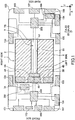
distribution unit 20 is arranged in the front side region in theaccommodating unit 6, in addition, the DC/DC converters components power supplies DC converters - As shown in
FIG. 3 , thedistribution unit 20 may be disposed in the front side region in theaccommodating unit 6, as well as the DC/DC converters component power supplies junction box 5 is disposed on the opposite side of the electricalcomponent power supplies DC converters - Further, as shown in
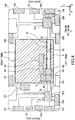
FIG. 4 , thedistribution unit 20 may be arranged in the front side region in theaccommodating unit 6, the DC/DC converters component power supplies DC converters junction box 5 is arranged on the front side of the electricalcomponent power supplies - Further, as shown in
FIG. 5 , thedistribution unit 20 may be arranged in the rear side region in theaccommodating unit 6, and the DC/DC converters electric power supplies DC converters - In this way, the disposition of the
distribution unit 20 in theaccommodation unit 6 and the arrangement of the electricalcomponent power supplies DC converters - Further, in the above-described embodiment, while the passing
portion 61 through which thewire harness 7 passes in the X direction that is front and rear direction of the vehicle is formed in theaccommodating unit 6, the passing portion may be formed extending in the other direction such as the Y direction or the like. Further, for example, when thedistribution unit 20 arranged at the end in the Y direction in theaccommodating unit 6 and the wire harness is easily drawn out from theaccommodating unit 6, the wire harness may be wired at a position adjacent to theaccommodating unit 6 in the Y direction with respect to theaccommodating unit 6 so as to extend along the X direction. - In the above embodiment, while the
power supply unit 1 includes two electricalcomponent power supplies DC converters - In addition, while the best configurations, methods, and the like for carrying out the present invention are disclosed in the above description, the present invention is not limited to this. That is, the present invention is illustrated and described specifically mainly with respect to a specific implementation, it is to be understood that without departing from the spirit and scope of the present invention in contrast to the embodiments described above, the shape, material, quantity, other details modifications can be made by those skilled in the art. Therefore, since the description that limits the shape, material, etc. disclosed above is described illustratively in order to facilitate the understanding of the present invention, but does not limit the present invention, the description in the name of the member with the limitation of part or all of the fixed part limitations on the shape, material, etc. thereof should be included in the present invention.
-
- 1 feed unit
- 2 drive power supply
- 3A, 3B power supply components
- 4A, 4B DC/DC converter (buck converter)
- 5 junction box (distribution unit)
- 6 storage unit
- 61 passage part
- 7 wire harness
- 10 automatic operation load (electrical component)
- 10B general load (electrical component)
Claims (3)
- A power supply unit for supplying power to a load mounted on a vehicle, comprising:a drive power supply for supplying electric power to a drive motor and electrical components as the load;at least one electrical component power supply for supplying power to the electrical components;at least one step-down converter provided between the drive power supply and the electrical components;a distribution unit for distributing power of the drive power supply and the electrical component power supply to a plurality of electrical components; andan accommodating unit for accommodating the drive power supply, wherein the electrical component power supply, the step-down converter and the distribution unit are accommodated in the accommodating unit.
- The power supply unit according to claim 1, further comprising
a wire harness connected to the distribution unit and led out of the accommodating unit, wherein
a passage portion is formed in the accommodating unit, that extends in a front-rear direction of the vehicle and passes therethrough the wire harness. - The power supply unit according to claim 1 or 2, wherein
a plurality of electrical component power supplies and a plurality of step-down converters are provided.
Applications Claiming Priority (1)
| Application Number | Priority Date | Filing Date | Title |
|---|---|---|---|
| JP2018104790A JP7433748B2 (en) | 2018-05-31 | 2018-05-31 | power supply unit |
Publications (2)
| Publication Number | Publication Date |
|---|---|
| EP3575119A1 true EP3575119A1 (en) | 2019-12-04 |
| EP3575119B1 EP3575119B1 (en) | 2020-11-25 |
Family
ID=66091902
Family Applications (1)
| Application Number | Title | Priority Date | Filing Date |
|---|---|---|---|
| EP19166721.1A Active EP3575119B1 (en) | 2018-05-31 | 2019-04-02 | Power supply unit |
Country Status (4)
| Country | Link |
|---|---|
| US (1) | US10960836B2 (en) |
| EP (1) | EP3575119B1 (en) |
| JP (1) | JP7433748B2 (en) |
| CN (1) | CN110549853B (en) |
Cited By (1)
| Publication number | Priority date | Publication date | Assignee | Title |
|---|---|---|---|---|
| EP4116123A1 (en) * | 2021-07-07 | 2023-01-11 | Yazaki Corporation | In-vehicle power supply system |
Families Citing this family (4)
| Publication number | Priority date | Publication date | Assignee | Title |
|---|---|---|---|---|
| JP7146168B2 (en) * | 2018-03-20 | 2022-10-04 | マツダ株式会社 | vehicle drive |
| JP7343457B2 (en) * | 2020-09-16 | 2023-09-12 | トヨタ自動車株式会社 | electric vehicle |
| IT202300005280A1 (en) * | 2023-03-21 | 2024-09-21 | Ferrari Spa | HYBRID OR ELECTRIC ROAD VEHICLE WITH SINGLE REFRIGERATION UNIT FOR BATTERY PACK AND POWER ELECTRONICS |
| JP7797445B2 (en) | 2023-07-14 | 2026-01-13 | 矢崎総業株式会社 | Power Supply Module |
Citations (4)
| Publication number | Priority date | Publication date | Assignee | Title |
|---|---|---|---|---|
| EP2402191A1 (en) * | 2009-02-24 | 2012-01-04 | Nissan Motor Co., Ltd. | Battery installation structure |
| JP2015214315A (en) * | 2014-05-13 | 2015-12-03 | 本田技研工業株式会社 | Electric device storage structure |
| WO2017173420A1 (en) * | 2016-04-01 | 2017-10-05 | Faraday & Future Inc. | Electric vehicle battery management |
| EP3321119A1 (en) * | 2016-11-10 | 2018-05-16 | Toyota Jidosha Kabushiki Kaisha | Vehicle power supply system |
Family Cites Families (51)
| Publication number | Priority date | Publication date | Assignee | Title |
|---|---|---|---|---|
| JP4346928B2 (en) * | 2003-03-04 | 2009-10-21 | 富士重工業株式会社 | Battery mounting structure |
| JP2005304122A (en) * | 2004-04-07 | 2005-10-27 | Denso Corp | Battery management device for hybrid vehicles |
| JP4365338B2 (en) * | 2005-03-17 | 2009-11-18 | トヨタ自動車株式会社 | Electronic component housing structure |
| JP2009289636A (en) * | 2008-05-30 | 2009-12-10 | Toyota Motor Corp | Temperature adjusting structure of power supply apparatus |
| US8125181B2 (en) * | 2008-09-17 | 2012-02-28 | Toyota Motor Engineering & Manufacturing North America, Inc. | Method and apparatus for hybrid vehicle auxiliary battery state of charge control |
| US8167262B2 (en) * | 2009-01-10 | 2012-05-01 | Ford Global Technologies, Llc | Power converter mounting assemblies |
| US9511659B2 (en) * | 2009-01-28 | 2016-12-06 | Steven Young | Method and apparatus for lawn care |
| JP5168308B2 (en) * | 2010-04-14 | 2013-03-21 | トヨタ自動車株式会社 | Power supply system and vehicle equipped with the same |
| US20110313583A1 (en) * | 2010-06-22 | 2011-12-22 | Unified Packet Systems Corp. | Integrated Wireless Power Control Device |
| WO2012078721A2 (en) * | 2010-12-07 | 2012-06-14 | Allison Transmission, Inc. | Energy storage system for hybrid electric vehicle |
| JP2012243424A (en) * | 2011-05-16 | 2012-12-10 | F-Bit Power Co Ltd | Charging system for electric vehicle or plug-in hybrid vehicle |
| JP5853417B2 (en) * | 2011-05-17 | 2016-02-09 | 日産自動車株式会社 | Battery pack structure for electric vehicles |
| US9677907B2 (en) * | 2013-03-14 | 2017-06-13 | Itron Inc | Intelligent receptacle |
| JP6070379B2 (en) * | 2013-04-10 | 2017-02-01 | トヨタ自動車株式会社 | On-vehicle converter |
| JP5899182B2 (en) * | 2013-10-23 | 2016-04-06 | 本田技研工業株式会社 | Electric vehicle |
| US20160009232A1 (en) * | 2014-07-10 | 2016-01-14 | Adam M. Budny | Power Toolbox, Power Toolbox Accessory Kit, and Related Methods |
| US10045427B2 (en) * | 2014-09-29 | 2018-08-07 | Philips Lighting Holding B.V. | System and method of autonomous restore point creation and restoration for luminaire controllers |
| JP6076318B2 (en) * | 2014-11-27 | 2017-02-08 | 矢崎総業株式会社 | Wire harness |
| JP6235529B2 (en) * | 2015-05-25 | 2017-11-22 | トヨタ自動車株式会社 | Electric vehicle and battery pack |
| JP6347235B2 (en) * | 2015-07-30 | 2018-06-27 | トヨタ自動車株式会社 | Control device for hybrid vehicle |
| US20170070090A1 (en) * | 2015-09-08 | 2017-03-09 | Weifield Group Consulting | Smart electrical outlet |
| JP6374894B2 (en) * | 2016-02-02 | 2018-08-15 | 矢崎総業株式会社 | Circuit body for vehicle |
| US10782327B2 (en) * | 2016-02-16 | 2020-09-22 | Panasonic Intellectual Property Management Co., Ltd. | Power supply system, power control device, and power supply device |
| US10168673B2 (en) * | 2016-03-01 | 2019-01-01 | International Business Machines Corporation | Analytic-based energy consumption control |
| BR112018074873B8 (en) * | 2016-06-01 | 2024-01-09 | Univ Pontificia Bolivariana | Method and device for detecting faults in transmission and distribution systems |
| WO2017222073A1 (en) * | 2016-06-24 | 2017-12-28 | 矢崎総業株式会社 | Vehicle circuit structure |
| WO2017222074A1 (en) * | 2016-06-24 | 2017-12-28 | 矢崎総業株式会社 | Vehicle circuit structure |
| US10295250B2 (en) * | 2016-08-08 | 2019-05-21 | Ford Global Technologies, Llc | Vehicle-based smart cooler |
| US11712980B2 (en) * | 2016-09-14 | 2023-08-01 | Ford Global Technologies, Llc | Vehicle power generation human machine interfaces |
| US10501032B2 (en) * | 2016-11-07 | 2019-12-10 | Toyota Motor Enigineering & Manufacturing North America, Inc. | Vehicle retractable power interface |
| CN114583369A (en) * | 2016-11-09 | 2022-06-03 | Cps 科技控股有限公司 | battery pack |
| JP2018185898A (en) * | 2017-04-24 | 2018-11-22 | 矢崎総業株式会社 | Electric wire and wire harness |
| US10791669B2 (en) * | 2017-07-07 | 2020-10-06 | The Toro Company | Turf vehicle having accessory attachment system |
| US20190013766A1 (en) * | 2017-07-07 | 2019-01-10 | John Stach | Mobile renewable energy power generator, management system, and distributed energy resources |
| JP6724876B2 (en) * | 2017-08-31 | 2020-07-15 | 株式会社デンソー | Power converter |
| US20190084506A1 (en) * | 2017-09-15 | 2019-03-21 | GM Global Technology Operations LLC | Power receptacle system for an automotive vehicle |
| US10763660B2 (en) * | 2017-11-14 | 2020-09-01 | Ford Global Technologies, Llc | Dual use vehicular AC generator |
| JP6731902B2 (en) * | 2017-11-27 | 2020-07-29 | 矢崎総業株式会社 | Power supply system |
| JP2019098782A (en) * | 2017-11-28 | 2019-06-24 | 矢崎総業株式会社 | Wire harness routing structure |
| US10892635B2 (en) * | 2018-01-11 | 2021-01-12 | Ford Global Technologies, Llc | Redundant power supply |
| DE102018104916A1 (en) * | 2018-03-05 | 2019-09-05 | Bender Gmbh & Co. Kg | Method for controlling a charging device of a vehicle and charging device of a vehicle for charging an electrical energy storage device of the vehicle |
| JP6710238B2 (en) * | 2018-05-25 | 2020-06-17 | 本田技研工業株式会社 | Vehicle power system |
| US10855070B2 (en) * | 2018-09-19 | 2020-12-01 | Ford Global Technologies, Llc | Vehicle and method of delivering electrical current to an outlet on the vehicle |
| CN110936727B (en) * | 2018-09-21 | 2021-06-15 | 精工爱普生株式会社 | Mobile devices |
| US11012587B2 (en) * | 2018-09-21 | 2021-05-18 | Seiko Epson Corporation | Mobile device with battery |
| US11059474B2 (en) * | 2018-10-09 | 2021-07-13 | Ford Global Technologies, Llc | Hybrid vehicle with electrical power outlet |
| US11043801B2 (en) * | 2018-10-09 | 2021-06-22 | Ford Global Technologies, Llc | Hybrid vehicle with electrical power outlet |
| JP7135722B2 (en) * | 2018-10-29 | 2022-09-13 | トヨタ自動車株式会社 | vehicle |
| JP7131316B2 (en) * | 2018-11-12 | 2022-09-06 | トヨタ自動車株式会社 | Self-driving equipment module mounting structure, self-driving electric vehicle equipped with the same, and self-driving equipment module cooling method |
| JP6845843B2 (en) * | 2018-12-14 | 2021-03-24 | 本田技研工業株式会社 | Vehicle power system |
| US10730447B1 (en) * | 2019-02-27 | 2020-08-04 | Ford Global Technologies, Llc | Pickup truck lockbox |
-
2018
- 2018-05-31 JP JP2018104790A patent/JP7433748B2/en active Active
-
2019
- 2019-04-02 EP EP19166721.1A patent/EP3575119B1/en active Active
- 2019-04-19 US US16/389,337 patent/US10960836B2/en active Active
- 2019-05-30 CN CN201910464054.6A patent/CN110549853B/en active Active
Patent Citations (5)
| Publication number | Priority date | Publication date | Assignee | Title |
|---|---|---|---|---|
| EP2402191A1 (en) * | 2009-02-24 | 2012-01-04 | Nissan Motor Co., Ltd. | Battery installation structure |
| JP2015214315A (en) * | 2014-05-13 | 2015-12-03 | 本田技研工業株式会社 | Electric device storage structure |
| WO2017173420A1 (en) * | 2016-04-01 | 2017-10-05 | Faraday & Future Inc. | Electric vehicle battery management |
| EP3321119A1 (en) * | 2016-11-10 | 2018-05-16 | Toyota Jidosha Kabushiki Kaisha | Vehicle power supply system |
| JP2018078752A (en) | 2016-11-10 | 2018-05-17 | トヨタ自動車株式会社 | Electric car |
Cited By (2)
| Publication number | Priority date | Publication date | Assignee | Title |
|---|---|---|---|---|
| EP4116123A1 (en) * | 2021-07-07 | 2023-01-11 | Yazaki Corporation | In-vehicle power supply system |
| US11749986B2 (en) | 2021-07-07 | 2023-09-05 | Yazaki Corporation | In-vehicle power supply system |
Also Published As
| Publication number | Publication date |
|---|---|
| CN110549853B (en) | 2022-11-11 |
| US20190366957A1 (en) | 2019-12-05 |
| US10960836B2 (en) | 2021-03-30 |
| JP2019209717A (en) | 2019-12-12 |
| JP7433748B2 (en) | 2024-02-20 |
| CN110549853A (en) | 2019-12-10 |
| EP3575119B1 (en) | 2020-11-25 |
Similar Documents
| Publication | Publication Date | Title |
|---|---|---|
| US10960836B2 (en) | Power supply unit | |
| JP5776852B2 (en) | High-voltage harness connection structure for electric vehicles | |
| JP5853417B2 (en) | Battery pack structure for electric vehicles | |
| US20210218101A1 (en) | Electric Vehicle | |
| US20230001869A1 (en) | Vehicle Power Supply Circuit | |
| US20150010795A1 (en) | Battery pack temperature control structure for electric vehicles | |
| US20150010782A1 (en) | Battery pack temperature control structure for electric vehicles | |
| JPWO2012157332A1 (en) | Battery pack structure for electric vehicles | |
| WO2012157315A1 (en) | Battery pack structure for electric vehicles | |
| EP3974239A1 (en) | Electric power supply system comprising a first and a second battery in a vehicle | |
| JP2015061414A (en) | Electric vehicle | |
| JP6738847B2 (en) | Vehicle power supply system | |
| US11186184B2 (en) | Electrically operated vehicle and charging system | |
| US20240239198A1 (en) | High voltage vehicle architecture | |
| CN114243895B (en) | Vehicle and power supply system thereof | |
| EP4251502B1 (en) | Smart vehicle | |
| US20250206247A1 (en) | Vehicle | |
| US20250229670A1 (en) | DC-DC Converters for Vehicles | |
| US20250229671A1 (en) | DC-DC Converters for Vehicles | |
| EP4585443A1 (en) | Dc-dc converters for vehicles | |
| JP4802793B2 (en) | Dual power supply vehicle power supply device | |
| JP2021176262A (en) | Power distribution system | |
| JP2025176480A (en) | Vehicle Power Supply Systems | |
| OA21498A (en) | Smart vehicle. | |
| CN117656872A (en) | A vehicle system architecture and vehicle |
Legal Events
| Date | Code | Title | Description |
|---|---|---|---|
| PUAI | Public reference made under article 153(3) epc to a published international application that has entered the european phase |
Free format text: ORIGINAL CODE: 0009012 |
|
| STAA | Information on the status of an ep patent application or granted ep patent |
Free format text: STATUS: REQUEST FOR EXAMINATION WAS MADE |
|
| 17P | Request for examination filed |
Effective date: 20190402 |
|
| AK | Designated contracting states |
Kind code of ref document: A1 Designated state(s): AL AT BE BG CH CY CZ DE DK EE ES FI FR GB GR HR HU IE IS IT LI LT LU LV MC MK MT NL NO PL PT RO RS SE SI SK SM TR |
|
| AX | Request for extension of the european patent |
Extension state: BA ME |
|
| RBV | Designated contracting states (corrected) |
Designated state(s): AL AT BE BG CH CY CZ DE DK EE ES FI FR GB GR HR HU IE IS IT LI LT LU LV MC MK MT NL NO PL PT RO RS SE SI SK SM TR |
|
| GRAP | Despatch of communication of intention to grant a patent |
Free format text: ORIGINAL CODE: EPIDOSNIGR1 |
|
| STAA | Information on the status of an ep patent application or granted ep patent |
Free format text: STATUS: GRANT OF PATENT IS INTENDED |
|
| INTG | Intention to grant announced |
Effective date: 20200821 |
|
| GRAS | Grant fee paid |
Free format text: ORIGINAL CODE: EPIDOSNIGR3 |
|
| GRAA | (expected) grant |
Free format text: ORIGINAL CODE: 0009210 |
|
| STAA | Information on the status of an ep patent application or granted ep patent |
Free format text: STATUS: THE PATENT HAS BEEN GRANTED |
|
| AK | Designated contracting states |
Kind code of ref document: B1 Designated state(s): AL AT BE BG CH CY CZ DE DK EE ES FI FR GB GR HR HU IE IS IT LI LT LU LV MC MK MT NL NO PL PT RO RS SE SI SK SM TR |
|
| REG | Reference to a national code |
Ref country code: GB Ref legal event code: FG4D |
|
| REG | Reference to a national code |
Ref country code: CH Ref legal event code: EP |
|
| REG | Reference to a national code |
Ref country code: DE Ref legal event code: R096 Ref document number: 602019001445 Country of ref document: DE |
|
| REG | Reference to a national code |
Ref country code: AT Ref legal event code: REF Ref document number: 1337898 Country of ref document: AT Kind code of ref document: T Effective date: 20201215 |
|
| REG | Reference to a national code |
Ref country code: IE Ref legal event code: FG4D |
|
| REG | Reference to a national code |
Ref country code: AT Ref legal event code: MK05 Ref document number: 1337898 Country of ref document: AT Kind code of ref document: T Effective date: 20201125 |
|
| REG | Reference to a national code |
Ref country code: NL Ref legal event code: MP Effective date: 20201125 |
|
| PG25 | Lapsed in a contracting state [announced via postgrant information from national office to epo] |
Ref country code: NO Free format text: LAPSE BECAUSE OF FAILURE TO SUBMIT A TRANSLATION OF THE DESCRIPTION OR TO PAY THE FEE WITHIN THE PRESCRIBED TIME-LIMIT Effective date: 20210225 Ref country code: GR Free format text: LAPSE BECAUSE OF FAILURE TO SUBMIT A TRANSLATION OF THE DESCRIPTION OR TO PAY THE FEE WITHIN THE PRESCRIBED TIME-LIMIT Effective date: 20210226 Ref country code: RS Free format text: LAPSE BECAUSE OF FAILURE TO SUBMIT A TRANSLATION OF THE DESCRIPTION OR TO PAY THE FEE WITHIN THE PRESCRIBED TIME-LIMIT Effective date: 20201125 Ref country code: PT Free format text: LAPSE BECAUSE OF FAILURE TO SUBMIT A TRANSLATION OF THE DESCRIPTION OR TO PAY THE FEE WITHIN THE PRESCRIBED TIME-LIMIT Effective date: 20210325 Ref country code: FI Free format text: LAPSE BECAUSE OF FAILURE TO SUBMIT A TRANSLATION OF THE DESCRIPTION OR TO PAY THE FEE WITHIN THE PRESCRIBED TIME-LIMIT Effective date: 20201125 |
|
| PG25 | Lapsed in a contracting state [announced via postgrant information from national office to epo] |
Ref country code: AT Free format text: LAPSE BECAUSE OF FAILURE TO SUBMIT A TRANSLATION OF THE DESCRIPTION OR TO PAY THE FEE WITHIN THE PRESCRIBED TIME-LIMIT Effective date: 20201125 Ref country code: IS Free format text: LAPSE BECAUSE OF FAILURE TO SUBMIT A TRANSLATION OF THE DESCRIPTION OR TO PAY THE FEE WITHIN THE PRESCRIBED TIME-LIMIT Effective date: 20210325 Ref country code: LV Free format text: LAPSE BECAUSE OF FAILURE TO SUBMIT A TRANSLATION OF THE DESCRIPTION OR TO PAY THE FEE WITHIN THE PRESCRIBED TIME-LIMIT Effective date: 20201125 Ref country code: PL Free format text: LAPSE BECAUSE OF FAILURE TO SUBMIT A TRANSLATION OF THE DESCRIPTION OR TO PAY THE FEE WITHIN THE PRESCRIBED TIME-LIMIT Effective date: 20201125 Ref country code: SE Free format text: LAPSE BECAUSE OF FAILURE TO SUBMIT A TRANSLATION OF THE DESCRIPTION OR TO PAY THE FEE WITHIN THE PRESCRIBED TIME-LIMIT Effective date: 20201125 Ref country code: BG Free format text: LAPSE BECAUSE OF FAILURE TO SUBMIT A TRANSLATION OF THE DESCRIPTION OR TO PAY THE FEE WITHIN THE PRESCRIBED TIME-LIMIT Effective date: 20210225 |
|
| REG | Reference to a national code |
Ref country code: LT Ref legal event code: MG9D |
|
| PG25 | Lapsed in a contracting state [announced via postgrant information from national office to epo] |
Ref country code: HR Free format text: LAPSE BECAUSE OF FAILURE TO SUBMIT A TRANSLATION OF THE DESCRIPTION OR TO PAY THE FEE WITHIN THE PRESCRIBED TIME-LIMIT Effective date: 20201125 |
|
| PG25 | Lapsed in a contracting state [announced via postgrant information from national office to epo] |
Ref country code: CZ Free format text: LAPSE BECAUSE OF FAILURE TO SUBMIT A TRANSLATION OF THE DESCRIPTION OR TO PAY THE FEE WITHIN THE PRESCRIBED TIME-LIMIT Effective date: 20201125 Ref country code: EE Free format text: LAPSE BECAUSE OF FAILURE TO SUBMIT A TRANSLATION OF THE DESCRIPTION OR TO PAY THE FEE WITHIN THE PRESCRIBED TIME-LIMIT Effective date: 20201125 Ref country code: SK Free format text: LAPSE BECAUSE OF FAILURE TO SUBMIT A TRANSLATION OF THE DESCRIPTION OR TO PAY THE FEE WITHIN THE PRESCRIBED TIME-LIMIT Effective date: 20201125 Ref country code: SM Free format text: LAPSE BECAUSE OF FAILURE TO SUBMIT A TRANSLATION OF THE DESCRIPTION OR TO PAY THE FEE WITHIN THE PRESCRIBED TIME-LIMIT Effective date: 20201125 Ref country code: LT Free format text: LAPSE BECAUSE OF FAILURE TO SUBMIT A TRANSLATION OF THE DESCRIPTION OR TO PAY THE FEE WITHIN THE PRESCRIBED TIME-LIMIT Effective date: 20201125 Ref country code: RO Free format text: LAPSE BECAUSE OF FAILURE TO SUBMIT A TRANSLATION OF THE DESCRIPTION OR TO PAY THE FEE WITHIN THE PRESCRIBED TIME-LIMIT Effective date: 20201125 |
|
| REG | Reference to a national code |
Ref country code: DE Ref legal event code: R097 Ref document number: 602019001445 Country of ref document: DE |
|
| PG25 | Lapsed in a contracting state [announced via postgrant information from national office to epo] |
Ref country code: DK Free format text: LAPSE BECAUSE OF FAILURE TO SUBMIT A TRANSLATION OF THE DESCRIPTION OR TO PAY THE FEE WITHIN THE PRESCRIBED TIME-LIMIT Effective date: 20201125 |
|
| PLBE | No opposition filed within time limit |
Free format text: ORIGINAL CODE: 0009261 |
|
| STAA | Information on the status of an ep patent application or granted ep patent |
Free format text: STATUS: NO OPPOSITION FILED WITHIN TIME LIMIT |
|
| PG25 | Lapsed in a contracting state [announced via postgrant information from national office to epo] |
Ref country code: NL Free format text: LAPSE BECAUSE OF FAILURE TO SUBMIT A TRANSLATION OF THE DESCRIPTION OR TO PAY THE FEE WITHIN THE PRESCRIBED TIME-LIMIT Effective date: 20201125 Ref country code: AL Free format text: LAPSE BECAUSE OF FAILURE TO SUBMIT A TRANSLATION OF THE DESCRIPTION OR TO PAY THE FEE WITHIN THE PRESCRIBED TIME-LIMIT Effective date: 20201125 Ref country code: IT Free format text: LAPSE BECAUSE OF FAILURE TO SUBMIT A TRANSLATION OF THE DESCRIPTION OR TO PAY THE FEE WITHIN THE PRESCRIBED TIME-LIMIT Effective date: 20201125 |
|
| 26N | No opposition filed |
Effective date: 20210826 |
|
| PG25 | Lapsed in a contracting state [announced via postgrant information from national office to epo] |
Ref country code: SI Free format text: LAPSE BECAUSE OF FAILURE TO SUBMIT A TRANSLATION OF THE DESCRIPTION OR TO PAY THE FEE WITHIN THE PRESCRIBED TIME-LIMIT Effective date: 20201125 Ref country code: MC Free format text: LAPSE BECAUSE OF FAILURE TO SUBMIT A TRANSLATION OF THE DESCRIPTION OR TO PAY THE FEE WITHIN THE PRESCRIBED TIME-LIMIT Effective date: 20201125 |
|
| PG25 | Lapsed in a contracting state [announced via postgrant information from national office to epo] |
Ref country code: LU Free format text: LAPSE BECAUSE OF NON-PAYMENT OF DUE FEES Effective date: 20210402 |
|
| REG | Reference to a national code |
Ref country code: BE Ref legal event code: MM Effective date: 20210430 |
|
| PG25 | Lapsed in a contracting state [announced via postgrant information from national office to epo] |
Ref country code: ES Free format text: LAPSE BECAUSE OF FAILURE TO SUBMIT A TRANSLATION OF THE DESCRIPTION OR TO PAY THE FEE WITHIN THE PRESCRIBED TIME-LIMIT Effective date: 20201125 Ref country code: FR Free format text: LAPSE BECAUSE OF NON-PAYMENT OF DUE FEES Effective date: 20210430 |
|
| PG25 | Lapsed in a contracting state [announced via postgrant information from national office to epo] |
Ref country code: IE Free format text: LAPSE BECAUSE OF NON-PAYMENT OF DUE FEES Effective date: 20210402 |
|
| PG25 | Lapsed in a contracting state [announced via postgrant information from national office to epo] |
Ref country code: IS Free format text: LAPSE BECAUSE OF FAILURE TO SUBMIT A TRANSLATION OF THE DESCRIPTION OR TO PAY THE FEE WITHIN THE PRESCRIBED TIME-LIMIT Effective date: 20210325 |
|
| PG25 | Lapsed in a contracting state [announced via postgrant information from national office to epo] |
Ref country code: BE Free format text: LAPSE BECAUSE OF NON-PAYMENT OF DUE FEES Effective date: 20210430 |
|
| REG | Reference to a national code |
Ref country code: CH Ref legal event code: PL |
|
| PG25 | Lapsed in a contracting state [announced via postgrant information from national office to epo] |
Ref country code: LI Free format text: LAPSE BECAUSE OF NON-PAYMENT OF DUE FEES Effective date: 20220430 Ref country code: CH Free format text: LAPSE BECAUSE OF NON-PAYMENT OF DUE FEES Effective date: 20220430 |
|
| PG25 | Lapsed in a contracting state [announced via postgrant information from national office to epo] |
Ref country code: CY Free format text: LAPSE BECAUSE OF FAILURE TO SUBMIT A TRANSLATION OF THE DESCRIPTION OR TO PAY THE FEE WITHIN THE PRESCRIBED TIME-LIMIT Effective date: 20201125 |
|
| PG25 | Lapsed in a contracting state [announced via postgrant information from national office to epo] |
Ref country code: HU Free format text: LAPSE BECAUSE OF FAILURE TO SUBMIT A TRANSLATION OF THE DESCRIPTION OR TO PAY THE FEE WITHIN THE PRESCRIBED TIME-LIMIT; INVALID AB INITIO Effective date: 20190402 |
|
| GBPC | Gb: european patent ceased through non-payment of renewal fee |
Effective date: 20230402 |
|
| PG25 | Lapsed in a contracting state [announced via postgrant information from national office to epo] |
Ref country code: GB Free format text: LAPSE BECAUSE OF NON-PAYMENT OF DUE FEES Effective date: 20230402 |
|
| PG25 | Lapsed in a contracting state [announced via postgrant information from national office to epo] |
Ref country code: GB Free format text: LAPSE BECAUSE OF NON-PAYMENT OF DUE FEES Effective date: 20230402 |
|
| PG25 | Lapsed in a contracting state [announced via postgrant information from national office to epo] |
Ref country code: MK Free format text: LAPSE BECAUSE OF FAILURE TO SUBMIT A TRANSLATION OF THE DESCRIPTION OR TO PAY THE FEE WITHIN THE PRESCRIBED TIME-LIMIT Effective date: 20201125 |
|
| PG25 | Lapsed in a contracting state [announced via postgrant information from national office to epo] |
Ref country code: MT Free format text: LAPSE BECAUSE OF FAILURE TO SUBMIT A TRANSLATION OF THE DESCRIPTION OR TO PAY THE FEE WITHIN THE PRESCRIBED TIME-LIMIT Effective date: 20201125 |
|
| PGFP | Annual fee paid to national office [announced via postgrant information from national office to epo] |
Ref country code: DE Payment date: 20250305 Year of fee payment: 7 |
|
| PG25 | Lapsed in a contracting state [announced via postgrant information from national office to epo] |
Ref country code: TR Free format text: LAPSE BECAUSE OF FAILURE TO SUBMIT A TRANSLATION OF THE DESCRIPTION OR TO PAY THE FEE WITHIN THE PRESCRIBED TIME-LIMIT Effective date: 20201125 |