WO2017222073A1 - Vehicle circuit structure - Google Patents
Vehicle circuit structure Download PDFInfo
- Publication number
- WO2017222073A1 WO2017222073A1 PCT/JP2017/023312 JP2017023312W WO2017222073A1 WO 2017222073 A1 WO2017222073 A1 WO 2017222073A1 JP 2017023312 W JP2017023312 W JP 2017023312W WO 2017222073 A1 WO2017222073 A1 WO 2017222073A1
- Authority
- WO
- WIPO (PCT)
- Prior art keywords
- line
- power supply
- sub
- branch
- harness
- Prior art date
Links
Images


Classifications
-
- B—PERFORMING OPERATIONS; TRANSPORTING
- B60—VEHICLES IN GENERAL
- B60R—VEHICLES, VEHICLE FITTINGS, OR VEHICLE PARTS, NOT OTHERWISE PROVIDED FOR
- B60R16/00—Electric or fluid circuits specially adapted for vehicles and not otherwise provided for; Arrangement of elements of electric or fluid circuits specially adapted for vehicles and not otherwise provided for
- B60R16/02—Electric or fluid circuits specially adapted for vehicles and not otherwise provided for; Arrangement of elements of electric or fluid circuits specially adapted for vehicles and not otherwise provided for electric constitutive elements
- B60R16/0207—Wire harnesses
- B60R16/0215—Protecting, fastening and routing means therefor
-
- B—PERFORMING OPERATIONS; TRANSPORTING
- B60—VEHICLES IN GENERAL
- B60R—VEHICLES, VEHICLE FITTINGS, OR VEHICLE PARTS, NOT OTHERWISE PROVIDED FOR
- B60R16/00—Electric or fluid circuits specially adapted for vehicles and not otherwise provided for; Arrangement of elements of electric or fluid circuits specially adapted for vehicles and not otherwise provided for
- B60R16/02—Electric or fluid circuits specially adapted for vehicles and not otherwise provided for; Arrangement of elements of electric or fluid circuits specially adapted for vehicles and not otherwise provided for electric constitutive elements
- B60R16/03—Electric or fluid circuits specially adapted for vehicles and not otherwise provided for; Arrangement of elements of electric or fluid circuits specially adapted for vehicles and not otherwise provided for electric constitutive elements for supply of electrical power to vehicle subsystems or for
-
- H—ELECTRICITY
- H01—ELECTRIC ELEMENTS
- H01B—CABLES; CONDUCTORS; INSULATORS; SELECTION OF MATERIALS FOR THEIR CONDUCTIVE, INSULATING OR DIELECTRIC PROPERTIES
- H01B7/00—Insulated conductors or cables characterised by their form
- H01B7/0045—Cable-harnesses
-
- H—ELECTRICITY
- H01—ELECTRIC ELEMENTS
- H01R—ELECTRICALLY-CONDUCTIVE CONNECTIONS; STRUCTURAL ASSOCIATIONS OF A PLURALITY OF MUTUALLY-INSULATED ELECTRICAL CONNECTING ELEMENTS; COUPLING DEVICES; CURRENT COLLECTORS
- H01R31/00—Coupling parts supported only by co-operation with counterpart
- H01R31/06—Intermediate parts for linking two coupling parts, e.g. adapter
-
- H—ELECTRICITY
- H01—ELECTRIC ELEMENTS
- H01B—CABLES; CONDUCTORS; INSULATORS; SELECTION OF MATERIALS FOR THEIR CONDUCTIVE, INSULATING OR DIELECTRIC PROPERTIES
- H01B7/00—Insulated conductors or cables characterised by their form
- H01B7/08—Flat or ribbon cables
- H01B7/0823—Parallel wires, incorporated in a flat insulating profile
Definitions
- the present invention relates to a vehicle circuit body arranged in a vehicle.
- a wire harness which is an assembly of a number of electric wires, is routed on the vehicle, and power is supplied by connecting the main power supply and the electrical components of each part via the wire harness.
- junction blocks are used to distribute power to multiple systems
- relay boxes are used to control power supply on / off for each system
- fuse boxes are used to protect each wire and load of the wire harness. Is generally used.
- the vehicle also includes a plurality of control units for controlling these electrical components, and the control unit and the electrical components are connected by a wire harness and can communicate with each other.
- the wire harness disclosed in Patent Document 1 includes a network transmission path and a circuit for supplying power, GND, and other signals.
- the wire harness includes a wire harness main line, a sub-wire harness, an optional sub-wire harness, and a network hub device.
- the present invention has been made in view of the above-described circumstances, and its purpose is to provide a structure for electrical connection between various electrical components and a power source on a vehicle and between electrical components, particularly a configuration of a main line portion.
- An object of the present invention is to provide a vehicle circuit body that is simplified and can easily add a new electric wire.
- a vehicle circuit body comprising a plurality of control boxes,
- the said trunk line is a circuit body for vehicles comprised with the wiring material which has at least 1 type of conductor among a flat type conductor, a round bar conductor, and a strand wire.
- the “predetermined current capacity” is a necessary and sufficient current capacity when, for example, all the electrical components that can be mounted on the mounting target vehicle are used and the “predetermined communication capacity” The communication capacity is necessary and sufficient when all electrical components that can be mounted on the mounting target vehicle are mounted and used.
- trunk line includes a branching portion that branches at least one of the power supply line and the communication line.
- trunk line further includes an earth line having a predetermined current capacity.
- a trunk line that is routed to the vehicle body with a predetermined current capacity and a predetermined communication capacity, and a plurality of control boxes that are distributed along the trunk line The vehicle circuit body having a simple structure can be configured by the branch line connecting the auxiliary machine to the main line via the. Further, the vehicle circuit body is configured by being divided into a trunk line that is commonly used for a plurality of vehicle types, grades, or options and a branch line that is changed by a plurality of vehicle types, grades, or optional accessories. Therefore, even if the number of vehicle types, grades, or optional accessories increases, it is only necessary to prepare branch lines having different wirings depending on a plurality of vehicle types, grades, or optional accessories. Cost can be reduced.
- the main power line requires a large cross-sectional area in order to ensure a predetermined current capacity. Therefore, when the power line is composed of a wiring material having a flat conductor with a strip-like cross-sectional shape, it becomes easy to bend in the thickness direction, and is routed along a predetermined wiring path. Work becomes easy. Moreover, when a power supply line is comprised by the wiring material which has a highly versatile round bar conductor and a strand, manufacture becomes easy and a bending direction becomes free and routing property becomes high.
- the routing material is configured by appropriately mixing a flat conductor, a round bar conductor, and a stranded wire, so that routing performance can be improved according to the routing route of the vehicle.
- a trunk line that is easy to manufacture.
- the routing material having a conductor suitable for the routing route of the vehicle can be used for each trunk line between the plurality of control boxes, and the routing property is further improved. To do.
- the main line is branched into a plurality of main lines at the branch portion, so that the control boxes distributed and arranged on each main line can be arranged in each part of the vehicle. . Therefore, it is easy to supply power and transmit / receive communication data (signals) via the branch lines connected to these control boxes, and to shorten the branch lines to the auxiliary devices arranged in each part of the vehicle. Become.
- the main power supply and the sub power supply are distributed in the main power supply line. Therefore, voltage fluctuation when the required power of each auxiliary machine is high can be suppressed by supplying current from each power source.
- power can be supplied from the other power source, and a power line that can be cut off can be configured.
- the main power supply and the sub power supply distributed in the vehicle are connected by the main power supply line, so that the regenerative energy can be easily recovered in the electric vehicle and the hybrid vehicle, and the energy recovery rate can be improved.
- by having a plurality of power supplies it is possible to support backup of power supplies, and the influence at the time of power failure can be reduced.
- the ground line is arranged in parallel with the power line in the trunk line, thereby preventing power noise from entering the communication line.
- the power line and the earth line are constructed and arranged in layers with wiring material having a flat conductor, and the noise resistance performance is further improved by increasing the surface area of the surfaces facing each other and reducing the gap between them. Can do.
- the structure for electrical connection between various electrical components and the power supply on the vehicle and between the electrical components, particularly the configuration of the trunk portion, is simplified, and the addition of new electric wires is also possible. In addition to being easy, it is possible to reduce the size and weight.
- FIG. 1 is an exploded perspective view showing a layout and connection state of each part in a state where the circuit body for a vehicle according to the first embodiment of the present invention is routed on the vehicle body, and an outline of each module mounted on the vehicle body. is there.
- FIG. 2 is a perspective view showing a state in which each module shown in FIG. 1 is mounted on the vehicle body.
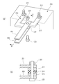
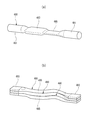
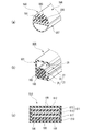
- 3A is a perspective view showing the supply-side control box shown in FIG. 1, and FIG. 3B is a cross-sectional view taken along the line AA in FIG. 3A.
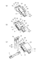
- 4 (a) to 4 (c) are perspective views showing an assembling procedure of the supply side control box shown in FIG.
- FIG. 5A and FIG. 5B are perspective views illustrating the circuit board according to this embodiment.
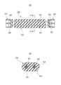
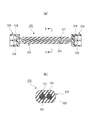
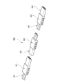
- FIG. 6 (a) is a perspective view showing the branch control box shown in FIG. 1
- FIG. 6 (b) is a perspective view showing the control box shown in FIG. 1
- FIG. 6 (c) is shown in FIG. It is a perspective view which shows the intermediate control box.
- FIG. 7 is an enlarged perspective view of a main part for explaining the instrument panel module shown in FIG.
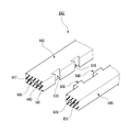
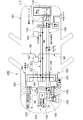
- FIG. 8 is a schematic configuration diagram illustrating a branch box according to the present embodiment.
- 9 (a) to 9 (c) are perspective views for explaining the structure of the branch box shown in FIG.
- FIG. 10 is an exploded perspective view showing a modification of the routing material according to the present embodiment.
- FIG. 11 is a main part perspective view showing a modification of the flat conductor according to the present embodiment.
- FIG. 12 is a perspective view for explaining a fuse configured in the flat conductor according to the present embodiment.
- FIG. 13A is a perspective view for explaining an example of battery connection between a power line and a ground line constituted by a flat conductor according to this embodiment
- FIG. 13B is a cross-sectional view taken along line BB in FIG. It is a cross-sectional arrow view.
- FIG. 14 is a perspective view for explaining an example of a connection structure of wiring members made of flat conductors according to the present embodiment.
- FIGS. 15A to 15C are perspective views for explaining the arrangement of power supply lines according to the present embodiment.
- FIG. 16A to FIG. 16D are cross-sectional views illustrating the arrangement of the routing material according to the present embodiment.
- FIG. 17A to 17E are cross-sectional views illustrating the arrangement of the routing material according to the present embodiment.
- FIG. 18A and FIG. 18B are cross-sectional views illustrating the arrangement of the routing material according to the present embodiment.
- FIG. 19A and FIG. 19B are perspective views for explaining a substrate connection structure for a round bar conductor according to the present embodiment.
- FIG. 20 is a perspective view for explaining a terminalized structure of a stranded wire according to this embodiment.
- FIG. 21A to FIG. 21D are enlarged views of main parts for explaining examples of the terminal structure of the power supply line according to the present embodiment.
- FIG. 22 is a perspective view for explaining an example of forming a round bar conductor according to the present embodiment.
- FIG. 23 is an explanatory diagram comparing the covering cross-sectional area of the conventional wire harness and the covering cross-sectional area of the routing material according to the present embodiment.
- FIG. 24A and FIG. 24B are a perspective view and a cross-sectional view of a main part for explaining a terminal connection structure of a round bar conductor according to this embodiment.
- FIG. 25A and FIG. 25B are a perspective view and a cross-sectional view of relevant parts for explaining a control box connection structure of a round bar conductor according to the present embodiment.
- FIG. 26A and FIG. 26B are perspective views of relevant parts for explaining a modification of the round bar conductor according to the present embodiment.
- FIG. 27 is a cross-sectional view illustrating a modified example of the routing material according to the present embodiment.
- FIG. 28 is a cross-sectional view illustrating a modified example of the routing material according to the present embodiment.
- FIG. 29A is a longitudinal sectional view for explaining a modification of the routing material according to the present embodiment
- FIG. 29B is a sectional view taken along the line CC in FIG. 29A.
- FIG. 30A to FIG. 30D are cross-sectional views for explaining modifications of the routing material according to the present embodiment.
- FIG. 31 (a) is a longitudinal sectional view for explaining a modification of the routing material according to the present embodiment
- FIG. 31 (b) is a DD sectional view in FIG.
- FIG. 32 is a plan view for explaining a modification of the routing material according to the present embodiment.
- FIG. 33 (a) to 33 (c) are a partial perspective view and a cross-sectional view for explaining an example of the arrangement form of the arrangement material according to this embodiment.
- FIG. 34 is a partial cross-sectional perspective view illustrating a modified example of the vehicle circuit body according to the present embodiment.
- FIG. 35 is a perspective view of a main part for explaining an example of a bonding configuration of the routing material according to the present embodiment.
- FIG. 36 is a perspective view of relevant parts for explaining an example of a bonding configuration of the routing material according to the present embodiment.
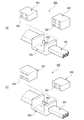
- FIGS. 37A and 37B are exploded perspective views of main parts for explaining a modification of the control box according to the present embodiment.
- FIG. 38B are partial cross-sectional perspective views for explaining a modified example of the routing material according to the present embodiment.
- FIG. 39A and FIG. 39B are perspective views for explaining an arrangement form example of the arrangement material according to the present embodiment.
- FIG. 40 is a schematic plan view illustrating a modified example of the vehicle circuit body according to the present embodiment.
- 41 (a) to 41 (e) are schematic plan views for explaining modifications of the vehicle circuit body according to the present embodiment.
- FIG. 42 is a schematic configuration diagram illustrating a modified example of the vehicle circuit body according to the present embodiment.
- FIG. 43 is a schematic configuration diagram illustrating a modified example of the vehicle circuit body according to the present embodiment.
- FIG. 44 is a schematic configuration diagram illustrating a modified example of the vehicle circuit body according to the present embodiment.
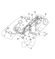
- FIG. 45 is a schematic perspective view showing a layout and a connection state of each part in a state in which the vehicle circuit body according to the modification of the present embodiment is routed on the vehicle body.
- FIG. 46 is a cross-sectional view of the main part for explaining the main-line dash panel penetration structure shown in FIG.
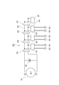
- FIG. 47 is a schematic plan view showing the layout and connection state of each part in a state where the vehicle circuit body according to the second embodiment of the present invention is routed on the vehicle body.
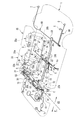
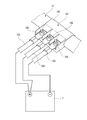
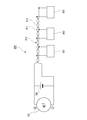
- FIG. 1 shows an outline of the layout and connection state of each part when the vehicle circuit body 10 according to the first embodiment of the present invention is routed on the vehicle body.
- the vehicle circuit body of the present invention is necessary for supplying power of a main power source such as an in-vehicle battery to auxiliary devices (electrical components) of each part of the vehicle body and for exchanging signals between the electrical components. It is used as a transmission path (see FIG. 1). That is, it is functionally the same as a general wire harness mounted on a vehicle, but is greatly different in shape and structure from a general wire harness.
- a trunk line having a power line having a predetermined current capacity, a communication line having a predetermined communication capacity, and an earth line has a shape like a backbone. It is composed of a simple wiring material 20.
- the “predetermined current capacity” is a necessary and sufficient current capacity when, for example, all the electrical components that can be mounted on the mounting target vehicle are used and the “predetermined communication capacity”
- the communication capacity is necessary and sufficient when all electrical components that can be mounted on the mounting target vehicle are mounted and used.
- various auxiliary machines electrical equipment
- a vehicle circuit body 10 has a power line 21 and a communication line 29 as basic components, and is a trunk line (backbone) routed in the vehicle body 1.
- Trunk line 15) and branch lines (instrument branch line sub-harness 31, front door branch line sub-harness 63, rear door branch line sub-harness 65, center console branch line sub-harness 66, front seat) connected to the electrical components of each part of the vehicle body
- Branch line sub-harness 67, rear seat branch line sub-harness 68, luggage branch line sub-harness 69) and power of the power supply line 21 supplied to the main line and signals of the communication line 29 are distributed to the branch lines connected to the main line.
- a plurality of control boxes (supply side control box 51, branch control box 53, intermediate control box) distributed along the main line 7, includes a control and boxes 55 and 59), the.
- the backbone trunk portion 15 of the vehicle circuit body 10 is broadly divided into an instrument panel backbone trunk portion 11 and a floor backbone trunk portion 13.
- the instrument panel backbone trunk portion 11 is linearly arranged in the left-right direction at a position along the surface of the dash panel 50 so as to be substantially parallel to the lean hose at a position above the lean hose (not shown).
- the instrument panel backbone trunk portion 11 may be fixed to a lean hose.
- the floor backbone trunk portion 13 is disposed so as to extend in the front-rear direction of the vehicle body 1 at a substantially central portion in the left-right direction of the vehicle body 1 along the vehicle interior floor.
- the tip is connected to an intermediate portion of the instrument panel backbone trunk portion 11.
- the connection part between the instrument panel backbone trunk part 11 and the floor backbone trunk part 13 is in a state where it can be electrically connected to each other via a branch part in a branch control box 53 described later. That is, the backbone trunk line portion 15 is configured in a shape similar to a T shape by the instrument panel backbone trunk line portion 11 and the floor backbone trunk line portion 13.
- instrument panel backbone trunk portion 11 is connected to an encoper sub harness 61 via a supply-side control box 51 disposed on the left side of the vehicle body 1 upstream of the backbone trunk portion 15.
- the encoder sub-harness 61 has a main power cable 81 that electrically connects the main battery 5 and the alternator 3, which are main power sources, arranged in an engine room (engine compartment) 41.
- the dash panel 50 there is a dash panel 50 at the boundary between the engine room 41 and the vehicle compartment 43, and it is required to completely seal the portion where the electrical connecting member penetrates the dash panel 50. That is, the dash panel 50 needs to have functions of insulating vibration from the engine room 41, reducing vibration and noise from the suspension, and blocking high heat, noise, odor, etc., in order to maintain comfort in the passenger compartment 43. In order not to impair this function, sufficient consideration is also required for the location where the electrical connection member penetrates.
- the vehicle circuit body 10 includes the instrument panel backbone trunk portion 11 and the floor backbone trunk portion 13 which are main components thereof, the supply side control box 51, the branch control box 53, All of the intermediate control box 57 and the control boxes 55 and 59 are arranged in the space on the vehicle compartment 43 side.
- the main power cable 81 connected to the supply-side control box 51 provided at the left end of the instrument panel backbone trunk portion 11 is routed so as to pass through the grommet 85 fitted in the through hole of the dash panel 50, and the engine room 41 It is connected to the inner encoder subharness 61. Thereby, the power of the main power source can be supplied to the supply side control box 51.
- the main power cable 81 can be made of a material that can be easily bent, can have a circular cross-sectional shape, or can be configured to have a cross-sectional area smaller than that of the instrument panel backbone trunk portion 11. Therefore, the grommet 85 can be easily sealed. It is possible to avoid the deterioration of workability when carrying out the routing work.
- the sub harness 71 connected to the supply side control box 51 passes through the dash panel 50.
- a desired electrical connection path can be realized by installing the sub-harness 73 connected to the control box 55 so as to penetrate the dash panel 50.
- the sub-harnesses 71 and 73 have a small cross-sectional area and can be easily bent, it is easy to seal a portion penetrating the dash panel 50.
- the instrument panel backbone trunk 11 is connected to an instrument panel branch sub-harness (branch line) 31 and a front door branch sub-harness (branch line) 63 via a supply-side control box 51 and a control box 55.
- the instrument panel branch sub-harness 31 is connected via a module connector C to the module driver 30b of the instrument panel harness 30a that is electrically connected to a control unit of an electrical component such as a meter panel or an air conditioner mounted on the instrument panel module 30.
- the front door branch sub-harness 63 is not in contact with the module driver 33b of the front door harness 33a that is electrically connected to a control unit of an electrical component such as a door lock or a power window mounted on the front door 33. It is desirable to be connected so that power can be fed and close proximity wireless communication is possible.
- rear backbone branch sub-harness (branch line) 65 the center console branch sub-harness (branch line) 66, and the front seat branch sub-harness (branch line) are connected to the floor backbone trunk 13 through the intermediate control box 57.
- a rear seat branch line sub-harness (branch line) 68, and the sub-battery 7 are connected.
- the rear door branch sub-harness 65 is capable of non-contact power supply to the module driver 35b of the rear door harness 35a that is electrically connected to a control unit of electrical components such as a door lock and a power window mounted on the rear door 35. It is desirable to be connected so that close proximity wireless communication is possible.
- the center console branch sub-harness 66 is a module for the module driver 39b of the center console harness 39a that is electrically connected to a control unit of an electrical component such as an air conditioner or an audio operation panel mounted on the center console 39. It is electrically connected via the connector C.
- the front seat branch sub-harness 67 is a module connector for the module driver 37b of the front seat harness 37a that is electrically connected to a control unit of electrical components such as electric reclining and seat heater mounted on the front seat 37. It is electrically connected via C.
- the rear seat branch sub-harness 68 is connected via a module connector C to the module driver 38b of the rear seat harness 38a that is electrically connected to a control unit of an electrical component such as an electric reclining or seat heater mounted on the rear seat 38. Electrically connected.
- a luggage branch sub-harness (branch line) 69 is connected to the floor backbone trunk part 13 via a control box 59 disposed behind the vehicle body 1 downstream of the trunk line.
- the luggage branch sub-harness 69 is electrically connected via a module connector C to a module driver (not shown) of the luggage harness that is electrically connected to the control unit of various electrical components in the luggage room. Is done.
- the module connector C can be connected to the control box together with power and ground power and signals so that power and signals can be efficiently sent to the backbone trunk 15 and each auxiliary machine. it can.
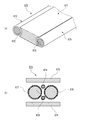
- the backbone trunk 15 of the vehicle circuit body 10 includes a power line 21, a communication line 29, and an earth line 27, and the routing material 20 having the flat conductor 100. It consists of Further, in the configuration shown in FIG. 1, since it is assumed that a sub-battery (sub-power source) 7 exists, the main power system ( A power supply line) 23 and a sub power supply system (power supply line) 25 are included.
- the routing material 20 is made of a strip-shaped metal material (for example, copper alloy or aluminum) having a flat cross-sectional shape for the power supply line 21, the ground line 27, and the communication line 29 in the backbone trunk 15.
- the flat conductor 100 is employed, and the flat conductor 100 whose periphery is covered with an insulating coating 110 is laminated in the thickness direction (see FIG. 1). That is, the main power supply system 23 is laminated on the sub power supply system 25 constituting the power supply line 21, and a pair of flat conductors, for example, are arranged in parallel on the earth line 27 laminated on the main power supply system 23.
- the communication lines 29 are stacked.
- the routing material 20 can allow a large current to pass, and the bending process in the thickness direction becomes relatively easy.
- the routing material 20 can be routed while the power line 21 and the ground line 27 are running side by side, and the ground line 27 is stacked between the communication line 29 and the power line 21. As a result, it is possible to prevent power supply noise from wrapping around.
- the power supply line 21 of the backbone trunk portion 15 needs a large cross-sectional area in order to ensure a predetermined current capacity.
- the power supply line 21 of the present embodiment has a strip-shaped flat conductor 100 with a flat cross-sectional shape.
- the wiring material 20 has a thickness, and the bending in the thickness direction is facilitated, and the work for routing along a predetermined routing path is facilitated.
- the vehicle circuit body 10 includes a supply-side control box 51 disposed at the upstream end of the backbone trunk section 15 (the left end of the instrument panel backbone trunk section 11), and a branch section in the middle of the backbone trunk section 15.
- Branch control box 53 arranged in (connecting part of instrument panel backbone trunk part 11 and floor backbone trunk part 13) and intermediate control box arranged in the middle of backbone trunk part 15 (intermediate part of floor backbone trunk part 13) 5 and control boxes 55 and 59 arranged at the downstream end of the backbone trunk section 15 (the right end of the instrument panel backbone trunk section 11 and the rear end of the floor backbone trunk section 13).
- the supply-side control box 51 includes a main power supply connection portion 120 for connecting the main power supply cable 81 to the instrument panel backbone trunk portion 11, and a front door branch subharness 63 and a subharness.
- a branch line connecting part 121 for connecting 71 is provided.
- the supply-side control box 51 connects the power system, the ground system, and the communication system of each circuit among the main power cable 81, the instrument panel backbone trunk 11, the front door branch sub-harness 63, and the sub-harness 71. Can do.
- the supply-side control box 51 accommodates a circuit board 125 in a case defined by a lower case 122 and an upper case 124, as shown in FIG.
- the male terminals 130 electrically connected to the flat conductors 100 of the sub power supply system 25, the main power supply system 23, and the ground line 27 are fitted into the three female terminals 127 mounted on the circuit board 125.
- a plurality of board connectors 131 provided at one end edge of the circuit board 125 to constitute the branch line connecting part 121 include the sub power source system 25, the main power source system 23, the ground line 27, and the The communication line 29 is electrically branched and connected via a circuit or bus bar configured on the substrate.
- the main power supply connection unit 120 includes a power supply connection unit 133 to which the power supply line 82 of the main power supply cable 81 is connected, and an earth connection unit 135 to which the earth line 84 is connected.
- the flat conductor 100 of the main power supply system 23 is connected to the stud bolt (power input terminal) 141 of the power supply connecting portion 133 embedded in the lower case 122.
- the flat conductor 100 of the earth line 27 is connected to the stud bolt (power input terminal) 143 of the earth connection part 135 embedded in the lower case 122.
- the communication line 29 is connected to the circuit board 125 via, for example, a board connector (not shown).
- the circuit board 125 is fixed to the lower case 122 so that each female terminal 127 is fitted to each male terminal 130 electrically connected to each flat conductor 100. Is done.
- a control unit 151 for distributing the power of the power line 21 and the signal of the communication line 29 to the encoder sub-harness 61, the front door branch sub-harness 63, and the sub-harness 71 is mounted on the circuit board 125.
- the circuit board 125 also includes a switching circuit 153 having a field-programmable gate array (FPGA) device and a circuit module as components necessary for switching the connection state of a plurality of electrical components (auxiliary equipment) and electrical components. Has been implemented.
- FPGA field-programmable gate array
- a terminal 86 crimped to the end of the power supply line 82 of the main power supply cable 81 is nut-fastened to the flat conductor 100 of the main power supply system 23 in the power supply connecting portion 133.
- a terminal 86 crimped to the end of the ground line 84 of the main power cable 81 is nut-fastened to the flat conductor 100 of the ground line 27 in the ground connection portion 135. In this way, the main power cable 81 can be connected and fixed to the instrument panel backbone trunk section 11.
- module connector C connected to the end portions of the instrument panel branch wire sub-harness 31, the front door branch wire sub-harness 63, and the sub-harness 71 is connected to the board connector 131 of the branch wire connection portion 121.
- the module connector C can transmit the power of the power supply line 21 and the earth line 27 and the signal of the communication line 29 to each electrical component.
- the branch control box 53 is arranged at a branch portion in the middle of the backbone trunk section 15 that is a connection section between the instrument panel backbone trunk section 11 and the floor backbone trunk section 13, and is not shown.
- a branch line connection part 121 for connecting a sub-harness (branch line) connected to the electrical component is provided.
- the branch control box 53 can connect the power supply system, the ground system, and the communication system of each circuit between the instrument panel backbone trunk section 11, the floor backbone trunk section 13, and the sub-harness.
- the branch control box 53 houses a circuit board 125 in a case defined by a lower case 122 and an upper case 124, and a plurality of branch control boxes 53 provided at one end edge of the circuit board 125.
- the sub power supply system 25, the main power supply system 23, the earth line 27, and the communication line 29 in the instrument panel backbone trunk section 11 are electrically branched and connected via circuits and bus bars formed on the board.
- the sub power supply system 25, the main power supply system 23, and the ground line 27 in the instrument panel backbone trunk section 11 and the floor backbone trunk section 13 are electrically connected to each other by welding or bolt fastening (see FIG. 14), for example. Connection can be fixed.
- the communication lines 29 in the instrument panel backbone trunk section 11 and the floor backbone trunk section 13 can be electrically connected and fixed by connector connection, for example.
- the control box 55 is disposed at the downstream end of the backbone trunk section 15, which is the right end of the instrument panel backbone trunk section 11, and connects the front door branch sub-harness 63 and the sub-harness 73.
- the branch line connection part 121 is provided.
- the control box 55 can connect the power supply system, the ground system, and the communication system of each circuit between the instrument panel backbone trunk section 11, the front door branch sub-harness 63 and the sub-harness 73.
- the control box 55 accommodates the circuit board 125 in a case defined by the lower case 122 and the upper case 124, and three female terminals 127 mounted on the circuit board 125.
- the male terminals 130 electrically connected to the flat conductors 100 of the sub power supply system 25, the main power supply system 23, and the earth line 27 are fitted (see FIG. 3B).
- a plurality of board connectors 131 provided at one end edge of the circuit board 125 to constitute the branch line connecting part 121 include the sub power source system 25, the main power source system 23, the ground line 27, and the The communication line 29 is electrically branched and connected via a circuit or bus bar configured on the substrate.
- the control box 59 disposed at the rear end of the floor backbone trunk 13 has the same configuration as the control box 55 described above.
- the intermediate control box 57 is arranged in the middle of the backbone trunk 15 that is the middle of the floor backbone trunk 13, and includes a rear door branch sub-harness 65, a center console branch sub A harness 66, a front seat branch line sub-harness 67, a rear seat branch line sub-harness 68, and a branch line connection part 121 for connecting the sub battery 7 are provided.
- the intermediate control box 57 is located between the floor backbone trunk 13, the rear door branch sub harness 65, the center console branch sub harness 66, the front seat branch sub harness 67, the rear seat branch sub harness 68, and the sub battery 7.
- the power supply system, ground system, and communication system of each circuit can be connected to each other.
- the intermediate control box 57 accommodates the circuit board 125 in a case defined by the lower case 122 and the upper case 124, and a plurality of intermediate control boxes 57 provided at one end edge of the circuit board 125.
- the sub power supply system 25, the main power supply system 23, the ground line 27, and the communication line 29 in the floor backbone trunk section 13 are electrically branched and connected via a circuit and a bus bar formed on the board. Has been.
- Each of the above-described control boxes (supply-side control box 51, branch control box 53, intermediate control box 57, and control boxes 55, 59) has a plurality of branch line connecting portions 121 corresponding to the grade of the mounting target vehicle and the destination specification.
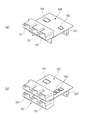
- the circuit board 126 shown in FIG. 5A includes three board connectors 131, a control part 151, and one switching circuit 153 that constitute the branch line connection part 121.
- the circuit board 125 shown in FIG. 5B includes six board connectors 131, a control part 151, and three switching circuits 153 constituting the branch line connection part 121.
- the circuit board 126 and the circuit board 125 can be accommodated in a case defined by a common lower case 122 and an upper case 124.
- the vehicle circuit body 10 includes an instrument panel branch sub-harness 31 connected as a branch line to the backbone trunk 15, a front door branch sub-harness 63, a rear door branch sub-harness 65, a center console branch A module in which the line sub-harness 66, the front seat branch sub-harness 67, the rear seat branch sub-harness 68, etc. are integrated with the instrument panel module 30, the front door 33, the rear door 35, the center console 39, the front seat 37, the rear seat 38, etc. It is configured as.
- the instrument panel branch sub-harness 31 is connected to the module driver 30 b of the instrument panel harness 30 a that is electrically connected to the control unit of the electrical component mounted on the instrument panel module 30.
- the front door branch sub-harness 63 is capable of non-contact power supply and proximity wireless to the module driver 33b of the front door harness 33a that is electrically connected to the control unit of the electrical component mounted on the front door 33. By being connected so as to be communicable, a module integrated with the front door 33 can be configured.
- the rear door branch sub-harness 65 is capable of non-contact power supply and proximity wireless communication to the module driver 35b of the rear door harness 35a that is electrically connected to the control unit of the electrical component mounted on the rear door 35. By being connected, it can be configured by a module integrated with the rear door 35.
- the center console branch sub-harness 66 is connected to the module driver 39b of the center console harness 39a that is electrically connected to the control unit of the electrical component mounted on the center console 39. It can be composed of an integral module.
- the front seat branch sub-harness 67 is connected to the module driver 37b of the front seat harness 37a that is electrically connected to the control unit of the electrical component mounted on the front seat 37. It can be composed of an integral module.
- the rear seat branch sub-harness 68 is a module integrated with the rear seat 38 by being connected to the module driver 38b of the rear seat harness 38a electrically connected to the control unit of the electrical component mounted on the rear seat 38. Can be configured.
- the instrument panel module 30 includes a plurality of instrument panel submodules such as a glove box 32, a center cluster 34, and a steering 36 along with the instrument panel body.
- a supply-side control box 51 disposed on the left side of the instrument panel backbone trunk 11 is located on the left side of the vehicle body 1 of the instrument panel module 30 to which the glove box 32 is attached. Therefore, when a mechanical relay or a mechanical fuse for power distribution is provided in the supply-side control box 51 electrically connected to the main battery 5 through the main power cable 81, the glove box 32 can be removed. The mechanical relay and mechanical fuse in the supply-side control box 51 can be easily accessed, and maintenance for exchanging them can be facilitated.
- the vehicle circuit body 10 can be provided with a branch box 161 in the middle of the backbone trunk 15 (for example, in the middle of the floor backbone trunk 13).
- the sub-battery 7 is connected to the branch box 161.
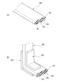
- the insulation coating 110 at predetermined locations of the sub power supply system 25, the main power supply system 23, and the ground line 27 is provided. After peeling off and exposing the flat conductors 100, connection terminals 171, 172, and 173 are connected to the flat conductors 100 by welding or the like.
- the sub power supply system 25, the main power supply system 23, and the ground line 27 are stacked so that the connection terminals 171, 172, and 173 are arranged in parallel.
- the case 162 in which the three stat bolts 167 are implanted covers the portion of the floor backbone trunk portion 13 where the insulation coating 110 has been peeled off, and the stat bolt 167 is connected to each other.
- the terminals 171, 172, and 173 are attached so as to pass through the through holes.
- the LA terminals 166 crimped to the ends of the power cables 163, 164, 165 connected to the sub-battery 7 are respectively inserted into the stat bolts 167 and fixed with nuts. Accordingly, the sub power supply system 25 and the main power supply system 23 are connected to the positive electrode of the sub battery 7 via the power cables 163 and 164, and the ground line 27 is connected to the negative electrode of the sub battery 7 via the power cable 165. . In this way, by providing the branch box 161 in the middle of the floor backbone trunk section 13, the sub battery 7 can be reliably and easily connected to the floor backbone trunk section 13.
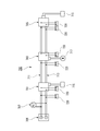
- the backbone main line portion 15 that is routed to the vehicle body 1 with a predetermined current capacity and a predetermined communication capacity, and the backbone main line portion. 15 through the five control boxes (supply-side control box 51, branch control box 53, intermediate control box 57, and control boxes 55, 59) distributed along the line 15 to the backbone trunk section 15.
- Branch lines to be connected (instrument panel branch sub harness 31, front door branch sub harness 63, rear door branch sub harness 65, center console branch sub harness 66, front seat branch sub harness 67, rear seat branch sub harness 68,
- a vehicle circuit body having a simple structure can be configured by the luggage branch sub-harness 69 and the like.
- a simple overall backbone backbone portion 15 composed of an instrument panel backbone trunk portion 11 extending in the left-right direction of the vehicle body 1 and a floor backbone trunk portion 13 extending in the front-rear direction of the vehicle body 1 at a substantially central portion of the vehicle body 1 is Easy to manufacture.
- the backbone main line unit 15 has a split structure that can be divided among the control boxes, and can also be connected to each other via the control box.
- branch lines instrument panel branches connected to a plurality of control boxes (supply-side control box 51, branch control box 53, intermediate control box 57, and control boxes 55, 59) distributed along the backbone trunk 15 are provided.
- Wire sub-harness 31, front door branch sub-harness 63, rear door branch sub-harness 65, center console branch sub-harness 66, front seat branch sub-harness 67, rear seat branch sub-harness 68, luggage branch sub-harness 69, etc. ) Is subdivided for each vehicle body area, the circuit specification difference in each area is dispersed, and the wire length can be shortened. Therefore, productivity can be improved, and branch lines that are subdivided and reduced in size can improve the packing rate and reduce transportation costs.
- the vehicle body 10 is divided into a harness 63, a rear door branch sub-harness 65, a center console branch sub-harness 66, a front seat branch sub-harness 67, a rear seat branch sub-harness 68, a luggage branch sub-harness 69, etc. Is configured. Therefore, even if the number of vehicle types, grades, or optional accessories increases, it is only necessary to prepare branch lines having different wirings depending on a plurality of vehicle types, grades, or optional accessories. In addition, cost can be reduced.
- the power line 21 and the communication line 29 are branches where the instrument panel backbone trunk section 11 in which the branch control box 53 is arranged and the floor backbone trunk section 13 are connected. It is configured in a T-shape branched at the part. Therefore, a plurality of control boxes (supply side control box 51, branch control box 53, distributed) are arranged in the instrument panel backbone trunk section 11 and the floor backbone trunk section 13 by the backbone trunk section 15 being branched into a plurality of branches. An intermediate control box 57 and control boxes 55 and 59) can be arranged in each part of the vehicle body 1, respectively.
- the auxiliary machines (electrical components) arranged in each part of the vehicle body 1 have branch lines (instrument panel branch sub-harness 31, front door branch sub-harness 63, rear door branch sub-harness 65) connected to these control boxes. , Power supply and transmission / reception of communication data (signals) via the center console branch sub-harness 66, front seat branch sub-harness 67, rear seat branch sub-harness 68, luggage branch sub-harness 69, etc.
- the branch line can be shortened.
- the trunk line of the present invention is not limited to the T-shape formed by the instrument panel backbone trunk section 11 and the floor backbone trunk section 13 but can take various forms such as an I-shape or an H-shape.
- the main battery (main power source) 5 and the sub batteries (sub power source) 7 are distributed in the power line 21 of the backbone trunk 15. Therefore, voltage fluctuations when the required power of each auxiliary machine (electrical component) is high can be suppressed by supplying current from each power source. Further, when power supply from one power source is interrupted due to a vehicle collision or the like, power can be supplied from the other power source, and the power supply line 21 can be configured.
- the main battery 5 and the sub-battery 7 distributed in the vehicle are connected by the power line 21 of the backbone trunk 15 so that it is easy to recover regenerative energy in an electric vehicle or a hybrid vehicle, and the energy recovery rate is improved. Can be made.
- by having a plurality of power supplies it is possible to support backup of power supplies, and the influence at the time of power failure can be reduced.
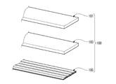
- FIG. 10 is an exploded perspective view showing a modification of the routing material according to the present embodiment.
- the routing member 180 constituting the backbone trunk portion includes a power supply line 181 and an earth line 183 made of a flat conductor made of aluminum, and a communication line 185 made of FPC (Flexible Printed Circuits). Therefore, the routing material 180 can be routed with the power supply line 181 and the ground line 183 running side by side next to each other, and the ground line 183 is stacked between the communication line 185 and the power supply line 181. As a result, it is possible to prevent power supply noise from wrapping around. Further, the power supply line 181 and the earth line 183 in the routing member 180 are formed of a flat conductor made of aluminum, and the communication line 185 is formed of FPC, so that a lightweight and thin backbone trunk portion can be obtained.
- FPC Flexible Printed Circuits
- FIG. 11 is a main part perspective view showing a modification of the flat conductor according to the present embodiment.
- a thin conductor 191 is appropriately formed on a part of the flat conductor 190 for constituting a power supply line and an earth line in the longitudinal direction. Therefore, the flat conductor 190 is easily bent in the thickness direction at the thin plate portion 191, and can be easily bent according to the shape of the vehicle body when routing the backbone trunk portion to the vehicle body 1. Therefore, the routing property of the backbone trunk line portion can be improved.
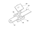
- FIG. 12 is a perspective view for explaining a fuse configured in the flat conductor according to the present embodiment.
- the power supply line 193 connected to the battery is made of a flat conductor, and a mounting hole 197 to be inserted into the battery post is formed at the tip.
- a fuse 195 is integrally formed on the base end side of the mounting hole 197.
- the fuse 195 is obtained by providing an acceptable body 199 made of a low-melting-point metal in a narrow diameter portion where the width of a flat conductor is narrowed. Further, the fuse 195 is covered with a fuse housing 192 having a transparent lid 194. According to the power supply line 193 integrally provided with such a fuse 195, it is not necessary to prepare a separate fuse when connecting the power supply line to the battery, and an increase in the number of components can be suppressed.
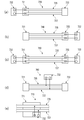
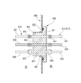
- FIG. 13 is a perspective view and a cross-sectional view for explaining an example of battery connection between a power supply line and a ground line configured by a flat conductor according to the present embodiment.
- the power supply line 201 and the earth line 203 in the backbone trunk line portion are made of a flat conductor, and a through hole is formed at the tip portion.
- An inwardly bent L-shaped bus bar 217 is electrically connected and fixed to the plus terminal 213 of the battery 210, and an inwardly bent L-shaped bus bar 215 is electrically connected to the minus terminal 211. It is fixed.
- the through holes formed at the ends of the intersecting bus bars 215 and 217 are arranged concentrically so that the bolts 221 can pass therethrough.
- the insulating sheet 219 with a hole is sandwiched between the ends of the bus bars 215 and 217, the power line 201 is overlaid on the upper surface of the bus bar 217, and the bolt that penetrates the ground line 203 is overlaid on the lower surface of the bus bar 215.
- a nut 223 is fastened and fixed to 221.
- the power supply line 201 is connected to the positive terminal 213 of the battery 210 via the bus bar 217 and the ground line 203 is connected to the negative terminal 211 of the battery 210 via the bus bar 215 without a complicated connection structure.
- the power supply line 201 and the ground line 203 made of a flat conductor can be connected to the battery 210 while being arranged in parallel, noise resistance can be improved. .
- FIG. 14 is a perspective view for explaining an example of a connection structure of wiring members made of flat conductors according to the present embodiment.
- the connection structure shown in FIG. 14 includes, for example, the sub power supply system 25, the main power supply system 23, and the ground line 27 in the instrument panel backbone trunk section 11 and the floor backbone trunk section 13 in the branch control box 53 shown in FIG.
- the flat conductors 100 are electrically connected and fixed to each other by bolt fastening.
- the insulation coating 110 of each of the sub power supply system 25, the main power supply system 23, and the earth line 27 in the instrument panel backbone trunk portion 11 is partially peeled to expose the flat conductors 100, and through holes are formed. Further, the insulating coating 110 at the tips of the sub power supply system 25, the main power supply system 23, and the earth line 27 in the floor backbone trunk portion 13 is peeled off to expose the flat conductor 100, and a through hole is formed.
- the sub power supply system 25, the main power supply system 23, and the ground line 27 in the floor backbone main line section 13 are placed on the sub-power supply system 25, the main power supply system 23, and the ground line 27 in the instrument panel backbone main section 11.
- the flat conductors 100 are overlapped.
- Insulating plates 237 with holes are respectively sandwiched between the superposed sub power supply system 25 and the superposed main power supply system 23 and between the superposed main power supply system 23 and the superposed earth line 27.
- the insulating nut 239 is fastened and fixed to the insulating bolt 238 penetrating them.
- the insulating bolt 238 and the insulating nut 239 are preferably formed of an electrically insulating engineering plastic or ceramic.
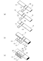
- FIG. 15 is a perspective view for explaining the arrangement of power supply lines according to the present embodiment.
- a wiring member 240 shown in FIG. 15A has a sub power supply system 241, a main power supply system 243, a ground line 245, and a communication line 247, each of which is composed of an electric wire having a stranded wire. Yes. Since the wiring material 240 is comprised with the electric wire which has a highly versatile strand wire, while being easy to manufacture, a bending direction becomes free and wiring property becomes high.
- the routing material 240 has a sufficient current capacity that can be used in combination with a backbone trunk portion of 12 volts and 48 volts. Therefore, 12 volts is usually supplied to the backbone trunk, and when the power consumption of the auxiliary equipment is large, 48 volts boosted by a DC / DC converter (high voltage / low voltage converter) is supplied by the backbone trunk. As described above, the backbone main line portion can switch between 12 volts and 48 volts V to facilitate the compensation of the power supply voltage for the auxiliary machine.
- the wiring member 250 shown in FIG. 15B includes a 12-volt power supply system 251, a 12-volt ground line 255, a 48-volt power supply system 253, and a 48-volt ground line 257. Each of which has a stranded wire. Therefore, the backbone trunk portion having the routing member 250 can also be used by switching between 12 volts and 48 volts V to facilitate compensation of the power supply voltage for the auxiliary machine.
- the wiring material 260 shown in FIG. 15C includes a 12-volt power supply system 251, a 12-volt and 48-V common earth line 259, and a 48-volt power supply system 253 arranged in parallel. It is comprised with the electric wire which has a wire. Therefore, the backbone trunk portion having the routing material 260 can be reduced in space and weight by reducing the number of wires.
- FIG. 16 is a perspective view illustrating the arrangement of the routing materials according to the present embodiment.
- the twist line of the main power supply system 272 and the earth line 274 is superimposed on the twist line of the sub power supply system 271 and the earth line 273, and the communication line 275 is placed thereon. , 276 twist lines are superposed. Therefore, the routing material 270 can improve noise resistance performance by canceling with a twist.
- a wiring member 280 shown in FIG. 16B is configured by sequentially laminating a ground line 283, a main power supply system 282, a ground line 283, and a communication line 285 on a sub power supply system 281 made of a flat conductor. Yes. Therefore, the routing material 280 can improve noise resistance performance by disposing the ground lines 283 in a distributed manner.
- the wiring material 290 shown in FIG. 16C is formed by covering the periphery of the sub power supply system 291 and the main power supply system 292 made of flat conductors with the braid 293 and the braid 294, respectively, and then stacking them in the plate thickness direction. A communication line 285 is laminated thereon. Therefore, the routing material 290 has improved noise resistance because the braid 293 and the braid 294 serve both as a ground and a shield.
- the ground line 303 is sandwiched between the sub power system 301 including noise and the communication line 305, and the ground line 304 is disposed between the main power system 302 and the communication line 305.
- the communication line 305 is shielded by pinching.
- the ground lines 304 and 303 are arranged above and below the communication line 305 to improve the shielding performance.
- the sub power supply system 301 and the main power supply system 302, and the ground lines 303 and 3043 are each formed of a flat conductor and laminated, so that the facing area between the power supply system and the ground line is wide and the gap is narrowed. As a result, the shielding performance is improved.
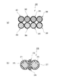
- FIG. 17 is a perspective view illustrating the arrangement of the routing materials according to the present embodiment.
- FIGS. 17 (a) to 17 (d) show a main power supply system 311 and a sub power supply system 312 each made of an electric wire having a stranded wire, an earth line 313 made of an electric wire having a stranded wire, and plastic light.
- It is sectional drawing which shows the wiring pattern of the wiring materials 310,320,330,340 comprised with the communication line 314 comprised with the fiber. In this way, by using optical communication that is resistant to noise for the communication line 314 in the routing materials 310, 320, 330, and 340, the degree of freedom in the routing pattern of the backbone trunk portion can be improved.
- the wiring member 350 shown in FIG. 17 (e) includes a main power supply system 351 and a sub power supply system 352 each made of a round bar conductor made of aluminum, and a pair of ground lines 313 made of electric wires having stranded wires.
- the communication line 314 made of a plastic optical fiber is bundled. Therefore, the communication line 314 disposed in the gap between the sub power supply system 352 formed of a round bar conductor and the pair of ground lines 313 is prevented from being damaged and can be easily routed to the vehicle body 1.
- FIG. 18 is a cross-sectional view illustrating the arrangement of the routing materials according to the present embodiment.
- the routing member 360 includes a 12-volt main power supply system 361 and a main earth line 362, a 12-volt sub power supply system 365 and a sub-earth line 366, and a 48-volt main earth line. 363 and the main power supply system 364, and the 48-volt sub-earth line 367 and the sub power supply system 368 are alternately arranged. Therefore, the routing material 360 has improved shielding performance, can be a seal dress, and noise filters can be reduced.
- the routing member 370 is composed of a main power supply system 371 and a sub power supply system 373, and a main power supply system 371 and a sub power supply system 373, which are each composed of a wire having a stranded wire.
- a pair of communication lines 376 and 378 that are provided in the upper and lower gaps between the main power supply system 371 and the sub power supply system 373 arranged in parallel. They are arranged parallel to each other.
- the routing member 370 can suppress the influence of noise on the communication lines 376 and 378 by covering the outer peripheral surfaces of the main power supply system 371 and the sub power supply system 373 with the ground lines 375 and 377, respectively.
- the communication lines 376 and 378 are provided in the upper and lower gaps between the two main power supply systems 371 and the sub power supply system 373, so that space can be saved. it can.
- FIG. 19 is a perspective view for explaining a substrate connection structure of round bar conductors according to the present embodiment.
- FIG. 19A for example, when electrically connecting a routing material 401 having a round bar conductor 403 to a circuit board 411 in the control box, first, insulation at a connection location of the routing material 401 is performed.
- the coating 404 is removed to expose the round bar conductor 403.
- the copper alloy crimp terminal 405 includes a pair of crimp pieces 407 and a pair of leads 409 inserted into the through holes 413 of the circuit board 411.
- the lead 409 of the crimping terminal 405 is connected to the through hole of the circuit board 411 as shown in FIG. Insert into 413 and solder.
- the round bar conductor 403 of the routing member 401 is electrically connected to a predetermined circuit of the circuit board 411.
- the substrate connection structure of the round bar conductor 403 it is not necessary to process the round bar conductor 403 in order to connect to the circuit board 411, and a dedicated press device, a press die, or the like can be used. No processing equipment is required, and processing costs can be reduced. That is, conventionally, in order to connect the round bar conductor to the mating terminal or electric wire, it is necessary to process the connecting portion flatly and perform welding or bolting, which increases the processing cost.
- the crimp terminal 405 can be attached at an arbitrary position of the round bar conductor 403. The degree of layout freedom can be increased.
- FIG. 20 is a perspective view for explaining a terminalized structure of a stranded wire according to this embodiment.
- the insulating coating 404 is removed to remove the wiring member 420.
- the stranded wire 421 exposed at the end is pressed into an LA terminal shape. Therefore, it is not necessary to connect the LA terminal to the end portion of the routing material 420, and the number of parts can be reduced.
- FIG. 21 is an enlarged view of a main part for explaining an example of the terminal structure of the power supply line according to the present embodiment.
- a terminal size connection terminal called “1.5 terminal” and a terminal size connection terminal called “4.8 terminal” are used as the connection terminal of the power supply line in the backbone trunk part according to the present embodiment. Is done.
- the male tab terminal 430 called “4.8 terminal” has a wide terminal width W of 4.8 mm, and the counterpart female terminal is also enlarged.
- the terminal connection portion in a three-dimensional U-shaped section like the male terminal 431 shown in FIG. 21B, the surface area (contact area with the mating terminal) is increased and the size is small.
- a structure capable of handling current is used.
- the terminal connection portion in a three-dimensional rectangular tube shape, the surface area can be increased to make it possible to cope with a large current even with a small size.
- the terminal connection portion is formed in a three-dimensional cylindrical shape, so that the surface area can be increased and the structure can cope with a large current even with a small size.
- FIG. 22 is a perspective view for explaining an example of forming a round bar conductor according to the present embodiment.
- a round bar conductor 403 made of aluminum is formed by using a secondary intermediate 445 at the time of manufacturing a core wire 447 of an aluminum electric wire. That is, the core wire 447 in a known aluminum electric wire forms, for example, a cylindrical primary intermediate 443 from an aluminum ingot 441, and then extends the primary intermediate 443 to form a long secondary intermediate 445. Further, it is formed by stretching the secondary intermediate 445 to a small diameter.
- the wiring material 401 can be formed simply by forming the secondary intermediate 445 as it is as the round bar conductor 403 and forming the insulating coating 404 around it, compared to the case where the round bar conductor is processed and manufactured exclusively, The processing cost of the round bar conductor 403 can be reduced.
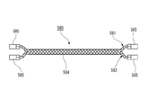
- FIG. 23 is an explanatory diagram comparing the covering cross-sectional area of the conventional wire harness and the covering cross-sectional area of the routing material according to the present embodiment.
- a conventional wire harness W / H provided with a power line, a ground line, and a communication line arranged in a vehicle body is a wire bundle made up of a number of wires 452, and has a cross-sectional diameter. Tends to increase in size.
- the wiring member 450 according to the present embodiment shown on the right side of FIG. 23 includes a power line 451 and an earth line 453 in which an insulating coating 404 is formed around an aluminum round bar conductor 403, and a plastic optical fiber.
- a communication line 456 configured by 454 is integrally held by a clamp 455 molded at a predetermined interval along the longitudinal direction.
- the cross-sectional area configuration of the insulating coating R and the conductor M in the wire harness W / H is compared with the cross-sectional area configuration of the insulating coating R and the conductor M in the routing material 450, the cross-sectional area of the conductor M is the same. Nevertheless, the cross-sectional area of the insulating coating R of the wire harness W / H is larger than the cross-sectional area of the insulating coating R of the routing material 450. That is, in the conventional wire harness W / H, a large number of electric wires 452 each have an insulation coating, whereas the routing material 450 has one power line 451, one earth line 453, and one communication line 456. As a result, the cross-sectional area of the insulating coating R can be reduced, and as a result, the routing member 450 can be greatly slimmed.
- the clamp 455 molded integrally with the routing material 450 has locking clips 459 protruding from both ends of the clamp body 457. Therefore, the routing material 450 can be easily routed and fixed to the vehicle body by inserting and locking these locking clips 459 into a through-hole such as a vehicle body panel.
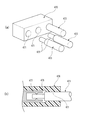
- FIG. 24 is a perspective view and a cross-sectional view of a main part for explaining a terminal connection structure of a round bar conductor according to this embodiment.
- the connection terminal 461 made of copper alloy includes a fixed portion 463 having a cylindrical inner surface that abuts on the outer surface of the round bar conductor 403, and a tab terminal portion 465 protruding from the outer surface of the fixed portion 463.
- the fixing portion 463 of the connection terminal 461 is fixed to the exposed round bar conductor 403 of the wiring member 401 by welding or ultrasonic waves. Therefore, by fitting the tab terminal portion 465 to the mating terminal provided on the circuit board, the round bar conductor 403 of the wiring member 401 is electrically connected to a predetermined circuit of the circuit board. Since the fixing portion 463 has a cylindrical inner surface that abuts on the outer surface of the round bar conductor 403, the connection terminal 461 can sufficiently secure a grounding area with respect to the round bar conductor 403 and ensure connection reliability.
- the backbone trunk line portion 460 configured by arranging a plurality of wiring members 401 in parallel has tab terminal portions 465 parallel to each other in the radial direction of the wiring member 401. Mates with the mating terminal in a protruding state. Therefore, the tab terminal portion 465 can be fitted to the mating terminal without changing the arrangement interval with respect to the plurality of wiring members 401 arranged in parallel.
- FIG. 25 is a perspective view and a cross-sectional view of a main part for explaining a control box connection structure of a round bar conductor according to this embodiment.
- the main power supply system, the sub power supply system, and the earth line that constitute the backbone trunk line portion are each configured by a round bar conductor 473 made of aluminum
- a terminal connection portion 475 having a small diameter is formed at the tip of each round bar conductor 473, and a mating female terminal 477 made of aluminum alloy that fits into the terminal connection portion 475 is disposed in each terminal accommodating chamber 471.
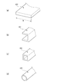
- FIG. 26 is a main part perspective view for explaining a modification of the round bar conductor according to the present embodiment.
- the routing member 480 shown in FIG. 26A includes a circular section 481 made of an aluminum round bar conductor, a plate-like part 483 made of a thick flat conductor made of aluminum, and a thin flat type made of aluminum.
- a thin plate-like portion 485 made of a conductor is connected and formed so that its shape changes seamlessly along the longitudinal direction.
- the plate-like portion 483 is easily bent in the plate thickness direction, and the thin plate-like portion 485 is further easily bent.
- the circular section 481 is harder to bend than the plate-like part 483 and the thin plate-like part 485, but the bending direction is free. Therefore, the backbone trunk portion formed of the routing material 480 can be easily three-dimensionally routed according to the routing route of the vehicle body.
- the routing member 490 shown in FIG. 26 (b) has a plate-like portion 493 made of a thick flat conductor made of aluminum and a circular section 495 made of an aluminum round bar conductor seamlessly along the longitudinal direction. Are connected so as to change the shape.
- the plate-like portion 493 has a lower height than the circular cross-section portion 495, and is used for a portion that needs to be routed while suppressing the height. Therefore, the backbone trunk portion formed by stacking a plurality of routing members 490 uses a plate-like portion 493 in a portion that needs to be routed while suppressing the height, and facilitates route routing in three dimensions.
- the circular section 495 is used, three-dimensional routing is facilitated according to the routing route of the vehicle body.
- these wiring materials 480 and 490 can be formed from aluminum round bars or rectangular bars without using aluminum wires, the manufacturing cost can be reduced.
- FIG. 27 is a cross-sectional view illustrating a modified example of the routing material according to the present embodiment.
- 27 includes a center conductor 501, an insulating layer 505 coaxially disposed outside the center conductor 501, and an earth line 503 made of a braided wire that covers the outer peripheral surface of the insulating layer 505. It is a coaxial cable.
- FIG. 28 is a cross-sectional view illustrating a modified example of the routing material according to the present embodiment.
- the wiring member 510 shown in FIG. 28 includes a power line 515 made of a plurality of litz wires (enameled wires) 511 and an earth line 513 arranged as a braided wire that surrounds the outside of the power line 515. Yes. Therefore, the routing material 510 is a wire that is compact and resistant to noise.
- FIG. 29 is a cross-sectional view illustrating a modified example of the routing material according to the present embodiment.
- the cabling member 520 has an oval cross section in a state where a power line 521 composed of a plurality of core wires 524 and a ground line 522 composed of a plurality of core wires 524 are arranged in parallel at a predetermined interval.
- the insulating coating 523 is covered.
- Terminals 525 are connected to both ends of the power supply line 521 and the earth line 522, respectively, and these terminals 525 are accommodated in the connector housing 527.
- the routing material 520 can cover the power supply line 521 and the earth line 522 with one insulating coating 523, and has a routing space as compared to a conventional wire harness in which a plurality of core wires are respectively covered with an insulating coating. The manufacturing cost can be reduced.
- FIG. 30 is a cross-sectional view illustrating a modified example of the routing material according to the present embodiment.
- the wiring material 530 shown in FIG. 30A is in a state where a power line 531 composed of a plurality of litz wires (enameled wires) 533 and a ground line 532 composed of a plurality of litz wires (enameled wires) 533 are close to each other. It is covered with an insulating coating 534 having an oval cross section. That is, the power supply line 531 and the earth line 532 do not have a coating layer, but are composed of the litz wire 533, so that even if they are close to each other, they are not short-circuited. Therefore, the routing member 530 can be made compact by covering the power supply line 531 having no coating layer and the ground line 532 with the insulating coating 534 in a close proximity.
- the wiring member 540 shown in FIG. 30B is covered with an insulating coating 543 having a circular cross section in a state where a power line 531 composed of a plurality of litz wires 533 and a ground line 532 composed of a plurality of litz wires 533 are close to each other. It has been broken.
- a power line 551 having a semicircular cross section composed of a plurality of litz wires 533 and a ground line 553 having a semicircular cross section composed of a plurality of litz wires 533 form a circular cross section.
- the insulating coating 5554 having a circular cross section is covered.
- the wiring member 560 shown in FIG. 30D includes a sub power supply line 561 composed of a plurality of litz wires 533, a main power supply line 562 composed of a plurality of litz wires 533, and an earth line 563 composed of a plurality of litz wires 533.
- a sub power supply line 561 composed of a plurality of litz wires 533
- a main power supply line 562 composed of a plurality of litz wires 533
- an earth line 563 composed of a plurality of litz wires 533.
- an insulating coating 564 having an elliptical cross section in a close state.
- FIG. 31 is a cross-sectional view illustrating a modified example of the routing material according to the present embodiment.
- the wiring member 570 is a state in which a power line 571 composed of a plurality of litz wires 533 and a ground line 573 composed of a plurality of litz wires 533 are twisted to increase the noise canceling effect. And is covered with an insulating coating 574 having an oval cross section. Terminals 578 are respectively connected to both ends of the power supply line 571 and the earth line 573, and these terminals 578 are accommodated in a connector housing 5579.
- the wiring member 570 can cover the twisted power supply line 571 and the ground line 573 with one insulating coating 574, and compared with a conventional twisted cable in which a plurality of core wires are covered with an insulating coating, respectively.
- the wiring space can be reduced.
- the routing material 570 can closely contact the litz wires 533, and can efficiently suppress noise.
- the wiring material 570 can form the insulation coating 574 while twisting the power supply line 571 and the earth line 573, it can be manufactured in one electric wire manufacturing process, and processing costs can be reduced.
- FIG. 32 is a plan view for explaining a modification of the routing material according to the present embodiment.
- a power line 581 composed of a plurality of litz wires 584 and a ground line 583 composed of a plurality of litz wires 584 are knitted together like a braided wire.
- Terminals 585 are connected to both ends of the power supply line 581 and the earth line 583 by soldering or ultrasonic waves, respectively.
- the power line 581 and the ground line 583 that are knitted can maintain independent current paths because the litz wires 584 do not conduct each other. Therefore, since the wiring material 580 has the power line 581 and the ground line 583 knitted so that the litz wires 584 are in close contact with each other, noise can be efficiently suppressed.
- FIG. 33 is a partial perspective view and a cross-sectional view for explaining an example of the arrangement of the arrangement material according to the present embodiment.
- the wiring member 590 in which the power line 591, the earth line 593, and the communication line 595 are covered with a semicircular insulating coating 596 is a lean hose having a semicircular cross section. It is routed integrally with 597. Therefore, the routing material 590 has improved space efficiency and can be reduced in size.
- the routing member 600 is arranged in a lean hose 601 having a rectangular cross section in a state where the sub power source system 25, the main power source system 23, the earth line 27, and the communication line 29 are laminated. It has been searched. Therefore, the routing material 600 is improved in space efficiency and can be reduced in size.
- the routing member 610 has a ground line 617 stacked on a communication line 619, and a ground power line 611 and a main power supply system 613 on the ground line 617.
- Sub power supply systems 615 are stacked.
- the outer skin 612 covers the circumference
- FIG. 34 is a partial cross-sectional perspective view illustrating a modified example of the vehicle circuit body according to the present embodiment.
- the main line between the plurality of control boxes 621, 623, 625 is composed of a wiring member 627 having a round bar conductor and a wiring member 629 having a flat conductor.
- the routing members 627 and 629 having conductors suitable for the routing path of the vehicle can be used for each trunk line between the plurality of control boxes 621, 623 and 625. The routing is further improved.
- FIG. 35 is a perspective view of a main part for explaining an example of a bonding configuration of the routing material according to the present embodiment.
- the routing material 630 is configured such that two thin plate-like routing materials 631 and 632 can be integrated by abutting and connecting the opposing surfaces.
- a protrusion 634 is formed on the right end surface of the routing material 631, and a recess 636 that is complementary to the protrusion 634 is formed on the left end surface of the routing material 632.
- each electrode that can contact the power line 633, the ground line 635, and the signal line 637 is also disposed on the left end surface of the wiring member 632 in the same manner.
- the routing material corresponding to various specifications is selected by selecting the types of the routing materials 631, 632 and the like that are standardized in advance, such as the shape of the connection part, the electrode specifications, and combining the selected members. 630 can be configured. In this case, it is possible to reduce the types of standardized routing members 630 and reduce the number of product numbers.
- FIG. 36 is a perspective view of a main part for explaining an example of the bonding configuration of the routing material according to the present embodiment.
- the wiring member 640 is configured so that two thin plate-shaped wiring members 642 and 646 can be integrated by abutting and connecting the opposing side surfaces.
- a plurality of recesses 636 are formed at predetermined intervals along the longitudinal direction on the right side surface of the routing material 642, and a protrusion 648 that is complementary to the recess 636 is formed on the left side surface of the routing material 646.
- a plurality are formed at predetermined intervals along the longitudinal direction.
- a 12-volt main power supply system 641, a 12-volt sub-power supply system 643, a 12-volt ground line 645, and a signal line 647 are arranged in parallel on the routing material 642, and each of them is stranded. It is comprised with the electric wire which has. Further, a 48-volt power supply system 651 and a 48-volt ground line 649 are arranged side by side on the wiring member 646, and each is constituted by an electric wire having a stranded wire.
- the wiring members 642 and 646 having different voltages into one wiring member 640. Moreover, it is possible to easily add a wiring member having a different voltage later. Further, the routing members 642 and 646 can be fixed by a simple operation of fitting the protrusion 648 and the recess 636.
- FIG. 37 is an exploded perspective view of main parts for explaining a modification of the control box according to the present embodiment.
- the control box 650 disposed along the backbone trunk line 661 is detachable from the control box body 658 connected to the backbone trunk line 661 and the tab terminal 656 of the control box body 658.
- the cartridge 653 has four connector ports 652 that constitute branch line connection portions to which branch line module connectors (not shown) are connected.
- the cartridge 655 has six connector ports 652 that constitute branch line connection portions to which branch line module connectors are connected.
- control box 650 can select the cartridges 653 and 655 as appropriate and install them in the common control box main body 658, so that the number of module connections can be varied. It can be easily set in the part 661.
- the control box 660 disposed along the backbone trunk 661 includes a control box main body 658 connected to the backbone trunk 661, and a cartridge 657 detachable from the control box main body 658. 659.
- the cartridge 657 has a configuration corresponding to a 48 volt power source having a connector port 654 corresponding to “4.8 terminals”.
- the cartridge 659 has a configuration corresponding to a 12-volt power source having a connector port 652 and the like corresponding to “1.5 terminals”.
- control box 660 can cope with 12 volt power supply, 48 volt power supply, and both power supply variations by selecting the cartridges 657 and 659 and mounting them in the common control box main body 658. Therefore, the backbone main line 661 provided with the control box 660 can cope with devices having different voltages by raising or lowering one voltage.
- FIG. 38 is a partial cross-sectional perspective view for explaining a modified example of the routing material according to the present embodiment.
- the routing member 670 includes an earth line 671 made of a flat conductor, and a main power supply system 673 and a sub power supply system 675 made of round bar conductors arranged on both sides of the earth line 671.
- the ground line 671 is formed with a semi-cylindrical concave surface 672 on the surface facing the main power supply system 673 and the sub power supply system 675 in order to increase the area facing the main power supply system 673 and the sub power supply system 675.
- the wiring member 670 has a larger facing area facing the main power supply system 673 and the sub power supply system 675, and noise resistance is improved.
- the ground line 671 is formed with a semi-cylindrical concave surface 672 because the main power supply system 673 and the sub power supply system 675 made of a round bar conductor are opposed to each other. When it consists of, a flat surface is formed. That is, the facing surface of the earth line 671 is a surface having a complementary shape corresponding to the shapes of the opposing main power supply system 673 and sub power supply system 675.
- the wiring member 674 is composed of a main power supply system 677 and a sub power supply system 678, which are each composed of an electric wire having a stranded wire, and are arranged in close proximity to each other.
- the main power supply system 677 and the sub power supply system 678 are arranged in parallel with the parallel arrangement direction of the sub power supply system 678 and a pair of ground lines 676, 676 made of flat conductors, and wires each having a stranded wire.
- a pair of communication lines 679 and 679 that are provided in a vertical gap between the flat earth line 676 and the adjacent main power supply system 677 and sub power supply system 678 are arranged in parallel to each other.
- the routing material 674 can suppress the influence of noise on the communication lines 679 and 679 by covering the top and bottom of the main power supply system 677 and the sub power supply system 678 with a pair of ground lines 676 made of a flat conductor. . Further, the communication lines 679 and 679 are routed in the upper and lower gaps between the flat ground line 676 and the adjacent main power supply system 677 and sub power supply system 678, so that space can be saved.
- FIG. 39 is a perspective view for explaining an arrangement form example of the arrangement material according to the present embodiment.
- the thin plate-like routing material 680 in which the main power supply system 681, the ground line 683, and the sub power supply system 685 arranged in parallel are covered with the insulating coating 687 is arranged in the thickness direction. It is possible to bend. However, when the vehicle body is routed, the routing material 680 tends to return to a straight shape by the elastic repulsion force, so that the routing work to the corners is difficult. Therefore, as shown in FIG.
- FIG. 40 is a schematic plan view illustrating a modified example of the vehicle circuit body according to the present embodiment.
- a backbone trunk 700 having a power line 711 and a ground line 713 is connected to a battery 706 and an alternator 707 that are power sources.
- a plurality of control boxes 701, 703, and 705 are distributed in the backbone trunk 700.
- An auxiliary machine 715 and a motor 717 are connected to each control box 701, 703, and 705.
- a plurality of sub-batteries 720 are connected to the power supply line 711 and the ground line 713 in and near the control boxes 701, 703, and 705.
- backbone backbone 700 can easily absorb noise by setting sub-battery 720 close to the noise source, and can suppress noise wraparound to the ECU.
- control boxes 701, 703, and 705 are arranged in a distributed manner, there is no problem regardless of the position of the backbone trunk section 700 where noise is generated or which is affected by noise. Will improve.
- FIG. 41 is a schematic plan view illustrating a modified example of the vehicle circuit body according to the present embodiment.
- the battery 732 can be connected to any position on the backbone trunk portion depending on vehicle conditions and the like. .
- the routing material (the power supply line 735 and the ground line 737) of the backbone trunk lines 730, 740, 750, and 760 that are routed between the control box 731 and the control box 733. ) Is preferably low impedance.
- the battery 732 can be installed in the control box 771 as in the backbone main line 770 shown in FIG.
- FIG. 42 is a schematic configuration diagram illustrating a modified example of the vehicle circuit body according to the present embodiment.
- the backbone trunk 780 having the power line 782 and the earth line 784 is connected to a battery 790 and an alternator 791 that are power sources.
- a plurality of control boxes 781, 783, and 785 are distributed in the backbone trunk line portion 780.
- Auxiliaries 787, 788, and 789 are connected to the control boxes 781, 783, and 785, respectively.
- a sub-battery can be connected to the most vehicle rear side of the backbone trunk line portion 780.
- the battery 790 and the alternator 791 are grounded to the vehicle body 792.
- the large current auxiliary machines 788 and 789 are also grounded to the vehicle body 792.
- the auxiliary machine 788 is body-grounded to the vehicle body 792 via a ground wire 793
- the auxiliary machine 789 is body-grounded to the vehicle body 792 via a bracket 794 that fixes a case to the vehicle body 792. That is, since the large-current auxiliary machines 788 and 789 pass through the body ground, the influence of noise can be reduced, and the ground voltage fluctuation and the noise of the alternator 791 can be suppressed.
- FIG. 43 is a schematic configuration diagram illustrating a modified example of the vehicle circuit body according to the present embodiment.
- the backbone trunk portion 800 includes a wiring member 810 in which a power line 811 made of, for example, an aluminum round bar conductor or a stranded wire and a ground line 813 are twisted.
- the routing material 810 is connected to a battery 790 and an alternator 791 that are power sources. Since the power supply line 811 and the ground line 813 are twisted, the noise canceling effect is improved and the resistance to external noise can be improved.
- FIG. 44 is a schematic configuration diagram illustrating a modified example of the vehicle circuit body according to the present embodiment.
- the backbone trunk line part 820 having the power supply line 828 and the earth line 829 is connected to a battery 790 and an alternator 791 which are power supplies.
- a plurality of control boxes 821, 823, 825, and 827 are distributed in the backbone trunk line portion 820.
- An auxiliary machine 833 is connected to each control box 821, 823, 825.
- annular ferrite 830 is attached to the backbone trunk portion 820 between the control boxes 821, 823, 825, and 827. Therefore, it is possible to prevent noise downstream of each control box 821, 823, 825, 827 from diffusing through the backbone trunk portion 820.
- FIG. 45 is a schematic perspective view showing a layout and a connection state of each part in a state in which the vehicle circuit body according to the modification of the present embodiment is routed on the vehicle body.
- a vehicle circuit body 900 shown in FIG. 45 includes, as basic components, a trunk line (backbone trunk line portion 915) that has a power line 931, a ground line 933, and a communication line 935 and is routed to the vehicle body 901.
- a trunk line backbone trunk line portion 915
- a communication line 935 and is routed to the vehicle body 901.
- Branch lines (instrument panel branch line sub-harness 965, front door branch line sub-harness 963, rear door branch line sub-harness 977, luggage branch line sub-harness 979) connected to electrical components in various parts of the vehicle body, and power lines supplied to the main line
- a plurality of control boxes (supply-side control box 951, branch control box) having a control unit for distributing the power of 931 and the signal of the communication line 935 to the branch lines connected to the main line and distributed along the main line 953, an intermediate control box 961, and control boxes 955, 957, 959, and 966).
- the backbone trunk portion 915 of the vehicle circuit body 900 is roughly divided into an instrument panel backbone trunk portion 911, a floor backbone trunk portion 913, and an encopa backbone trunk portion 919.
- the instrument panel backbone trunk portion 911 is linearly arranged in the left-right direction at a position along the surface of the dash panel 950 so as to be substantially parallel to the lean hose at a position above the lean hose (not shown).
- the instrument panel backbone trunk 911 may be fixed to a lean hose.
- the floor backbone trunk portion 913 is arranged so as to extend in the front-rear direction of the vehicle body 901 at a substantially central portion in the left-right direction of the vehicle body 901 along the vehicle interior floor.
- a leading end portion of a rising portion 917 linearly extending in the direction is connected to a joint box 920 attached to a through hole of the dash panel 950.
- the leading end of the rising portion 918 branched and connected to the floor backbone trunk portion 913 is connected to the middle portion of the instrument panel backbone trunk portion 911.
- an encopa backbone backbone 919 is connected to the floor backbone trunk 913 via a joint box 920 attached to a through hole of the dash panel 950.
- the ENCOPA backbone trunk 919 routed in the engine room 41 of the vehicle is connected to the main battery 5 as a main power supply via a branch line subharness 975 connected to the supply side control box 951.
- Branch line sub-harnesses 971 and 971 are connected to the supply-side control box 951 and the control box 959.
- the dash panel 950 there is a dash panel 950 at the boundary between the engine room 41 and the passenger compartment 43, and it is required to completely seal the portion where the electrical connecting member penetrates the dash panel 950.
- the dash panel 950 needs to have functions of insulating vibration from the engine room 41, reducing vibration and noise from the suspension, and blocking high heat, noise, odor, etc., in order to maintain comfort in the passenger compartment 43. In order not to impair this function, sufficient consideration is also required for the location where the electrical connection member penetrates.
- the joint box 920 includes relay terminals 923, 925, 927 that penetrate through the housing 921, and a packing 922 that seals between the dash panel 950.
- the power line 931, the earth line 933, and the communication line 935 in the rising part 917 of the floor backbone trunk part 913, and the power line 931, the earth line 933, and the communication line 935 in the encopa backbone part 919 are relay terminals. Both ends of 923, 925, and 927 are connected by bolt fastening with bolts 941 and connector coupling with connectors 943.
- the floor backbone trunk part 913 and the encopa backbone trunk part 919 are connected in a liquid-tight manner through a joint box 920 attached to a through hole of the dash panel 950.
- FIG. 47 is a schematic plan view showing the layout and connection state of each part in a state where the vehicle circuit body according to the second embodiment of the present invention is routed on the vehicle body.
- the circuit body 1000 for a vehicle shown in FIG. 47 includes, as basic components, a backbone trunk portion 1015 that is a trunk routed in a vehicle body 1001 of a so-called plug-in hybrid vehicle, and branches connected to electrical components of each portion of the vehicle body.
- a plurality of control boxes (supply side control box 1051, branch control box 1053, intermediate control box 1057, control box 1055, 1059), high voltage battery pack 1110 and power control unit 1220
- a high-voltage cable 1300 disposed in the lower part of the vehicle body for connecting
- the high voltage battery pack 1110 transmits the high voltage power of the high voltage battery 1130 to the high voltage cable 1300 via the high voltage J / B 1140.
- the electric power transmitted from the high voltage cable 1300 to the power control unit 1220 is sent to the motor generator and engine 1210 via the DC / DC converter 1230.
- the high-voltage J / B 1140 is connected to a floor backbone trunk line 1013 and an instrument panel backbone trunk line 1011 of the backbone trunk line 1015 via a DC / DC converter 1120.
- the power cable connected to the supply side control box 1051 is connected to the main battery 1005 via the fusible link 1020.
- Main battery 1005 is also connected to DC / DC 1230 of power control unit 1220 via fusible link 1022.
- the vehicular circuit body 1000 can achieve power redundancy by arranging the DC / DC converter 1230 and the DC / DC converter 1120 at the front and rear of the vehicle.
- the backbone main line unit 1015 can step down the power of the high voltage battery pack 1110 by the DC / DC converter 1120 and supply it as a sub power source. That is, the fusible links 1020 and 1022 are arranged at the end of the backbone trunk line 1015, and when the front or rear is short-circuited, the circuit is cut off and power is supplied from one of the DC / DC converter 1230 or the DC / DC converter 1120. Can continue (backup).
- the structure for electrical connection between various electrical components and the power source on the vehicle and between the electrical components, particularly the configuration of the main line portion, is simplified. New electric wires can be easily added, and the size and weight can be reduced.
- a trunk line (backbone trunk line portion 15) that is arranged in the vehicle body with a power line (21) having a predetermined current capacity and a communication line (29) having a predetermined communication capacity;
- Branch lines connected to the accessory instrument panel branch sub-harness 31, front door branch sub-harness 63, rear door branch sub-harness 65, center console branch sub-harness 66, front seat branch sub-harness 67, rear seat branch Sub-harness 68, luggage branch sub-harness 69),
- a plurality of control boxes supply side control box 51, branch control box 53, intermediate control box 57, control boxes 55, 59)
- the trunk line is a vehicle circuit body (10) composed of a wiring member (20) having at least one kind of conductors among a flat conductor (100), a round bar conductor (403), and a strande
- the trunk line includes a branching portion that branches at least one of the power supply line and the communication line.
- a sub power source (sub battery 7) different from the main power source (main battery 5) of the power line is connected to the main line.
- the trunk line further includes an earth line (27) having a predetermined current capacity.
- the structure for the electrical connection between various electrical components and the power supply on a vehicle and between electrical components, especially the structure of a trunk part can be simplified, and the addition of a new electric wire can also be performed easily.
- a circuit body can be provided.
- the present invention that exhibits this effect is useful for a vehicle circuit body that is routed in a vehicle.
- Vehicle Circuit Body 15 Backbone Main Line (Main Line) 21 Power line 27 Ground line 29 Communication line 31 Instrument panel branch line sub-harness (branch line) 51 Supply side control box 53 Branch control box 57 Intermediate control box 55 Control box 59 Control box 63 Front door branch sub-harness (branch line) 65 Rear door branch sub-harness (branch line) 66 Center console branch sub-harness (branch line) 67 Front seat branch line sub-harness (branch line) 68 Rear seat branch sub-harness (branch line) 69 luggage branch sub-harness (branch line) 100 flat conductor
Abstract
This vehicle circuit structure (10) is equipped with: a backbone main line portion (15) that is disposed in a vehicle body and is provided with a power line (21) having a prescribed current-carrying capacity and a communication line (29) having a prescribed channel capacity; an instrument panel branch line sub-harness (31) and the like connected to auxiliary equipment; and a supply-side control box (51), a branching control box (53), an intermediate control box (57), and control boxes (55, 59) that are all distributed along the main line and provided with a control unit for distributing, to the instrument panel branch line sub-harness (31) and the like connected to the main line, power from the power line (21) and signals from the communication line (29), both of which are supplied to the main line. The main line is formed from a wiring material (20) having a flat conductor (100).
Description
本発明は、車両に配索される車両用回路体に関する。
The present invention relates to a vehicle circuit body arranged in a vehicle.
車両上においては、例えば主電源であるオルタネータ(発電機)やバッテリから膨大な数の様々な電装品のそれぞれに対して電源電力を適切に供給する必要がある。また、このような電源電力の供給に用いるシステムにおいては、必要に応じて電力供給のオンオフを切り替える機能や、電装品に過大な電流が流れた場合に系統毎に電流を遮断するための機能も搭載する必要がある。
On a vehicle, for example, it is necessary to appropriately supply power to each of a huge number of various electrical components from an alternator (generator) which is a main power source or a battery. Also, in such a system used for power supply, there is a function for switching on / off the power supply as necessary, and a function for cutting off the current for each system when an excessive current flows through the electrical components. It is necessary to install.
一般的な車両においては、多数の電線の集合体であるワイヤハーネスを車両上に配索し、このワイヤハーネスを介して、主電源と各部の電装品との間を接続し電力の供給を行っている。また、電源電力を複数系統に分配するためにジャンクションブロックを用いたり、電力供給のオンオフを系統毎に制御するためにリレーボックスを用いたり、ワイヤハーネスの各電線や負荷を保護するためにヒューズボックスを用いることが一般的である。
In a general vehicle, a wire harness, which is an assembly of a number of electric wires, is routed on the vehicle, and power is supplied by connecting the main power supply and the electrical components of each part via the wire harness. ing. Also, junction blocks are used to distribute power to multiple systems, relay boxes are used to control power supply on / off for each system, and fuse boxes are used to protect each wire and load of the wire harness. Is generally used.
また、車両には、これらの電装品を制御するための制御部も複数備えており、制御部と電装品とはワイヤハーネスにより接続され、互いに通信可能となっている。
特許文献1に示されているワイヤハーネスは、ネットワーク伝送路と、電源やGND、その他の信号を供給するための回路とを備えている。また、このワイヤハーネスは、ワイヤハーネス幹線と、サブワイヤハーネスと、オプションサブワイヤハーネスと、ネットワークハブ装置とを備えている。 The vehicle also includes a plurality of control units for controlling these electrical components, and the control unit and the electrical components are connected by a wire harness and can communicate with each other.
The wire harness disclosed inPatent Document 1 includes a network transmission path and a circuit for supplying power, GND, and other signals. The wire harness includes a wire harness main line, a sub-wire harness, an optional sub-wire harness, and a network hub device.
特許文献1に示されているワイヤハーネスは、ネットワーク伝送路と、電源やGND、その他の信号を供給するための回路とを備えている。また、このワイヤハーネスは、ワイヤハーネス幹線と、サブワイヤハーネスと、オプションサブワイヤハーネスと、ネットワークハブ装置とを備えている。 The vehicle also includes a plurality of control units for controlling these electrical components, and the control unit and the electrical components are connected by a wire harness and can communicate with each other.
The wire harness disclosed in
近年、このような電源系や通信系を含む車両システムは、搭載される電装品の増加や制御の複雑化などにより高度化が進んでいる。また、自動運転技術も急速に進化しており、この自動運転に対応するために各種機能に対する安全要求も高まっている。
これに伴い、車体上に配索されるワイヤハーネスの構造が複雑化する傾向にある。したがって、例えば特許文献1のようにワイヤハーネス幹線と、サブワイヤハーネスと、オプションサブワイヤハーネスとを組み合わせ、全体として複雑な形状のワイヤハーネスを構成し、車体上の様々な箇所に配置される様々な電装品との接続を可能にしている。 In recent years, a vehicle system including such a power supply system and a communication system has been advanced due to an increase in mounted electrical components and a complicated control. In addition, automatic driving technology is rapidly evolving, and safety requirements for various functions are increasing in order to cope with this automatic driving.
Accordingly, the structure of the wire harness routed on the vehicle body tends to be complicated. Therefore, for example, as disclosed inPatent Document 1, a wire harness main line, a sub-wire harness, and an optional sub-wire harness are combined to form a wire harness having a complicated shape as a whole, and variously arranged at various locations on the vehicle body. Connection with various electrical components.
これに伴い、車体上に配索されるワイヤハーネスの構造が複雑化する傾向にある。したがって、例えば特許文献1のようにワイヤハーネス幹線と、サブワイヤハーネスと、オプションサブワイヤハーネスとを組み合わせ、全体として複雑な形状のワイヤハーネスを構成し、車体上の様々な箇所に配置される様々な電装品との接続を可能にしている。 In recent years, a vehicle system including such a power supply system and a communication system has been advanced due to an increase in mounted electrical components and a complicated control. In addition, automatic driving technology is rapidly evolving, and safety requirements for various functions are increasing in order to cope with this automatic driving.
Accordingly, the structure of the wire harness routed on the vehicle body tends to be complicated. Therefore, for example, as disclosed in
また、車両に搭載される電装品の増加に伴い、ワイヤハーネスを構成する各電線の径が太くなったり、電線本数が増えることになるため、ワイヤハーネス全体が大型化したり、重量が増大する傾向にある。また、ワイヤハーネスを搭載する車種の違いや車両に搭載するオプション電装品の種類の増加に伴って、製造すべきワイヤハーネスの種類および品番が増えるため、ワイヤハーネスを構成する部品の共通化が難しく、部品コストや製造コストが増大してしまう。
In addition, as the number of electrical components mounted on the vehicle increases, the diameter of each wire constituting the wire harness becomes thicker or the number of wires increases, so the whole wire harness tends to increase in size and weight. It is in. In addition, the types of wire harnesses to be manufactured and the part numbers increase with the difference in the types of vehicles in which the wire harnesses are mounted and the types of optional electrical components mounted on the vehicles. , Parts cost and manufacturing cost will increase.
また、ワイヤハーネスを制作する作業工程においては、所定の配索形状に仕上げるために、ワイヤハーネスを構成する多数の電線の束を事前に指定された経路に沿うように長い距離に亘り引き回すことになり、作業時間が長くかかる。また、ワイヤハーネスの幹線部分では、ほぼすべての電線が集まるため、束ねられる電線本数が多くなり、重くなる。
In addition, in the work process of producing a wire harness, in order to finish a predetermined wiring shape, a bundle of a large number of electric wires constituting the wire harness is routed over a long distance along a route designated in advance. It takes a long time to work. Moreover, since almost all electric wires gather in the trunk part of a wire harness, the number of electric wires bundled increases and becomes heavy.
また、例えば当初の設計時に想定していなかった新たな電装品を車両に搭載する場合には、当該電装品と他の電装品との間で特別な信号を伝送する経路を確保したり、電源電力を供給するために、新たな電線をワイヤハーネスに追加しなければならない。しかし、ワイヤハーネスは構造や形状が複雑であり、既存のワイヤハーネスに対して後から別の電線を追加することは非常に難しい。したがって、種類や品番が異なる新たなワイヤハーネスを設計し、別の製品として作り直す必要がある。
Also, for example, when installing new electrical components that were not assumed at the time of initial design in the vehicle, a route for transmitting a special signal between the electrical components and other electrical components can be secured, In order to supply power, new wires must be added to the wire harness. However, the structure and shape of the wire harness is complicated, and it is very difficult to add another electric wire to the existing wire harness later. Therefore, it is necessary to design a new wire harness of a different type and product number and recreate it as another product.
本発明は、上述した事情に鑑みてなされたものであり、その目的は、様々な電装品と車両上の電源との間および電装品同士の電気接続のための構造、特に幹線部分の構成を簡素化し、新たな電線の追加も容易にできる車両用回路体を提供することにある。
The present invention has been made in view of the above-described circumstances, and its purpose is to provide a structure for electrical connection between various electrical components and a power source on a vehicle and between electrical components, particularly a configuration of a main line portion. An object of the present invention is to provide a vehicle circuit body that is simplified and can easily add a new electric wire.
本発明に係る上記目的は、下記構成により達成される。
(1) 所定の電流容量を有する電源ラインと、所定の通信容量を有する通信ラインとを有して車体に配索される幹線と、
補機に接続される枝線と、
前記幹線に供給される前記電源ラインの電力及び前記通信ラインの信号のうち少なくとも一方を前記幹線に接続される前記枝線へ分配するための制御部を有し、前記幹線に沿って分散配置された複数の制御ボックスと、を備える車両用回路体であって、
前記幹線は、平型導体、丸棒導体及び撚り線のうち少なくとも一種類の導体を有する配索材で構成される車両用回路体。
なお、「所定の電流容量」とは、例えば取付対象車両に搭載可能な全ての電装品が搭載されて使用される際に必要十分な電流容量であり、「所定の通信容量」とは、例えば取付対象車両に搭載可能な全ての電装品が搭載されて使用される際に必要十分な通信容量である。 The above object of the present invention is achieved by the following configuration.
(1) a main line routed in a vehicle body having a power line having a predetermined current capacity and a communication line having a predetermined communication capacity;
A branch line connected to the auxiliary machine;
A controller for distributing at least one of the power of the power supply line supplied to the trunk line and the signal of the communication line to the branch lines connected to the trunk line, and is distributed along the trunk line A vehicle circuit body comprising a plurality of control boxes,
The said trunk line is a circuit body for vehicles comprised with the wiring material which has at least 1 type of conductor among a flat type conductor, a round bar conductor, and a strand wire.
The “predetermined current capacity” is a necessary and sufficient current capacity when, for example, all the electrical components that can be mounted on the mounting target vehicle are used and the “predetermined communication capacity” The communication capacity is necessary and sufficient when all electrical components that can be mounted on the mounting target vehicle are mounted and used.
(2) 前記配索材は、複数種の前記導体が混在して構成される上記(1)に記載の車両用回路体。
(2) The wiring member according to (1), wherein the wiring member is configured by mixing a plurality of types of conductors.
(3) 複数の前記制御ボックス間における前記幹線が、異なる種類の前記導体を有する配索材で構成される上記(1)又は(2)に記載の車両用回路体。
(3) The vehicle circuit body according to (1) or (2), wherein the trunk line between the plurality of control boxes is made of a wiring material having the different types of conductors.
(4) 前記幹線は、前記電源ライン及び前記通信ラインのうち少なくとも一方を分岐する分岐部を有する上記(1)~(3)の何れか1つに記載の車両用回路体。
(4) The vehicle circuit body according to any one of (1) to (3), wherein the trunk line includes a branching portion that branches at least one of the power supply line and the communication line.
(5) 前記幹線には、前記電源ラインの主電源とは別のサブ電源が接続される上記(1)~(4)の何れか1つに記載の車両用回路体。
(5) The vehicle circuit body according to any one of (1) to (4), wherein a sub power source different from the main power source of the power line is connected to the main line.
(6) 前記幹線が、所定の電流容量を有するアースラインをさらに備える上記(1)~(5)の何れか1つに記載の車両用回路体。
(6) The vehicle circuit body according to any one of (1) to (5), wherein the trunk line further includes an earth line having a predetermined current capacity.
上記(1)の構成の車両用回路体によれば、所定の電流容量及び所定の通信容量を有して車体に配索される幹線と、この幹線に沿って分散配置された複数の制御ボックスを介して補機を幹線に接続する枝線とによって、単純な構造の車両用回路体を構成することができる。
また、複数の車種、グレード又はオプションに共通して用いられる幹線と、複数の車種、グレード又はオプションの補機によって変更される枝線とに分けて車両用回路体が構成される。そこで、車種、グレード又はオプションの補機が増加したとしても、複数の車種、グレード又はオプションの補機によって配線が異なる枝線のみを準備すればよいため、車両用回路体の製造の容易化およびコストの低減を図ることができる。
なお、幹線の電源ラインは、所定の電流容量を確保するために大きな断面積が必要である。そこで、断面形状が偏平な帯状の平型導体を有する配索材で電源ラインが構成された場合には、厚み方向の折り曲げが容易になり、所定の配索経路に沿って配索するための作業が容易になる。また、汎用性の高い丸棒導体や撚り線を有する配索材で電源ラインが構成される場合には、製造が容易になると共に、曲げ方向が自由となって配索性が高くなる。 According to the vehicle circuit body configured as described in (1) above, a trunk line that is routed to the vehicle body with a predetermined current capacity and a predetermined communication capacity, and a plurality of control boxes that are distributed along the trunk line The vehicle circuit body having a simple structure can be configured by the branch line connecting the auxiliary machine to the main line via the.
Further, the vehicle circuit body is configured by being divided into a trunk line that is commonly used for a plurality of vehicle types, grades, or options and a branch line that is changed by a plurality of vehicle types, grades, or optional accessories. Therefore, even if the number of vehicle types, grades, or optional accessories increases, it is only necessary to prepare branch lines having different wirings depending on a plurality of vehicle types, grades, or optional accessories. Cost can be reduced.
Note that the main power line requires a large cross-sectional area in order to ensure a predetermined current capacity. Therefore, when the power line is composed of a wiring material having a flat conductor with a strip-like cross-sectional shape, it becomes easy to bend in the thickness direction, and is routed along a predetermined wiring path. Work becomes easy. Moreover, when a power supply line is comprised by the wiring material which has a highly versatile round bar conductor and a strand, manufacture becomes easy and a bending direction becomes free and routing property becomes high.
上記(2)の構成の車両用回路体によれば、平型導体、丸棒導体及び撚り線を適宜混在させて配索材を構成することで、車両の配索経路に応じて配索性がよく、製造が容易な幹線を得ることができる。
According to the vehicle circuit body having the configuration (2), the routing material is configured by appropriately mixing a flat conductor, a round bar conductor, and a stranded wire, so that routing performance can be improved according to the routing route of the vehicle. Well, it is possible to obtain a trunk line that is easy to manufacture.
上記(3)の構成の車両用回路体によれば、複数の制御ボックス間における幹線毎に、車両の配索経路に適した導体を有する配索材を用いることができ、配索性が更に向上する。
According to the vehicle circuit body having the configuration of (3) above, the routing material having a conductor suitable for the routing route of the vehicle can be used for each trunk line between the plurality of control boxes, and the routing property is further improved. To do.
上記(4)の構成の車両用回路体によれば、幹線が分岐部で複数の幹線に分岐されることにより、各幹線に分散配置される制御ボックスをそれぞれ車両の各部に配置することができる。そこで、車両の各部に配置された補機には、これら制御ボックスに接続された枝線を介しての電力供給や通信データ(信号)の送受信が容易になり、枝線の短線化も可能となる。
According to the vehicle circuit body having the configuration of (4) above, the main line is branched into a plurality of main lines at the branch portion, so that the control boxes distributed and arranged on each main line can be arranged in each part of the vehicle. . Therefore, it is easy to supply power and transmit / receive communication data (signals) via the branch lines connected to these control boxes, and to shorten the branch lines to the auxiliary devices arranged in each part of the vehicle. Become.
上記(5)の構成の車両用回路体によれば、幹線の電源ラインに主電源とサブ電源が分散配置される。そこで、各補機の要求電力が高い場合の電圧変動を各電源からの電流供給で抑制できる。また、車両衝突等により一方の電源からの電力供給が遮断されたような場合には、他方の電源から電力供給することができ、切れない電源ラインを構成することができる。
更に、車両に分散配置された主電源とサブ電源が幹線の電源ラインでつながれることで、電気自動車やハイブリッド車における回生エネルギーの回収が容易になり、エネルギー回収率を向上させることができる。
また、複数の電源を持つことで、電源のバックアップ対応が可能となり、電源異常時の影響を小さくできる。 According to the vehicle circuit body having the configuration of (5) above, the main power supply and the sub power supply are distributed in the main power supply line. Therefore, voltage fluctuation when the required power of each auxiliary machine is high can be suppressed by supplying current from each power source. In addition, when power supply from one power source is interrupted due to a vehicle collision or the like, power can be supplied from the other power source, and a power line that can be cut off can be configured.
Further, the main power supply and the sub power supply distributed in the vehicle are connected by the main power supply line, so that the regenerative energy can be easily recovered in the electric vehicle and the hybrid vehicle, and the energy recovery rate can be improved.
In addition, by having a plurality of power supplies, it is possible to support backup of power supplies, and the influence at the time of power failure can be reduced.
上記(6)の構成の車両用回路体によれば、幹線における電源ラインにアースラインが並走して配索されることで、通信ラインに対する電源ノイズの回り込みを防止することができる。
また、平型導体を有する配索材で電源ライン及びアースラインが構成されて積層配置され、互いに対向する面の表面積を増やし、両者の隙間を小さくすることで、耐ノイズ性能を更に向上させることができる。 According to the vehicle circuit body having the configuration of the above (6), the ground line is arranged in parallel with the power line in the trunk line, thereby preventing power noise from entering the communication line.
In addition, the power line and the earth line are constructed and arranged in layers with wiring material having a flat conductor, and the noise resistance performance is further improved by increasing the surface area of the surfaces facing each other and reducing the gap between them. Can do.
本発明の車両用回路体によれば、様々な電装品と車両上の電源との間および電装品同士の電気接続のための構造、特に幹線部分の構成を簡素化し、新たな電線の追加も容易にできると共に、小型化及び重量の低減が可能になる。
According to the vehicle circuit body of the present invention, the structure for electrical connection between various electrical components and the power supply on the vehicle and between the electrical components, particularly the configuration of the trunk portion, is simplified, and the addition of new electric wires is also possible. In addition to being easy, it is possible to reduce the size and weight.
以上、本発明について簡潔に説明した。更に、以下に説明される発明を実施するための形態(以下、「実施形態」という。)を添付の図面を参照して通読することにより、本発明の詳細は更に明確化されるであろう。
The present invention has been briefly described above. Further, the details of the present invention will be further clarified by reading through a mode for carrying out the invention described below (hereinafter referred to as “embodiment”) with reference to the accompanying drawings. .
本発明に関する具体的な実施形態について、各図を参照しながら以下に説明する。
Specific embodiments relating to the present invention will be described below with reference to the drawings.
(車両用回路体)
まず、車両用回路体の基本的な構成について説明する。
本発明の第1実施形態における車両用回路体10を車体上に配索した状態における各部のレイアウトおよび接続状態の概要を図1に示す。
本発明の車両用回路体は、車載バッテリなどの主電源の電力を車体各部の補機(電装品)に対してそれぞれ供給したり、電装品同士の間で信号のやりとりを行うために必要な伝送経路としたりして利用されるものである(図1参照)。即ち、機能的には車両に搭載される一般的なワイヤハーネスと同様であるが、形状や構造が一般的なワイヤハーネスとは大きく異なる。 (Vehicle circuit body)
First, the basic configuration of the vehicle circuit body will be described.
FIG. 1 shows an outline of the layout and connection state of each part when thevehicle circuit body 10 according to the first embodiment of the present invention is routed on the vehicle body.
The vehicle circuit body of the present invention is necessary for supplying power of a main power source such as an in-vehicle battery to auxiliary devices (electrical components) of each part of the vehicle body and for exchanging signals between the electrical components. It is used as a transmission path (see FIG. 1). That is, it is functionally the same as a general wire harness mounted on a vehicle, but is greatly different in shape and structure from a general wire harness.
まず、車両用回路体の基本的な構成について説明する。
本発明の第1実施形態における車両用回路体10を車体上に配索した状態における各部のレイアウトおよび接続状態の概要を図1に示す。
本発明の車両用回路体は、車載バッテリなどの主電源の電力を車体各部の補機(電装品)に対してそれぞれ供給したり、電装品同士の間で信号のやりとりを行うために必要な伝送経路としたりして利用されるものである(図1参照)。即ち、機能的には車両に搭載される一般的なワイヤハーネスと同様であるが、形状や構造が一般的なワイヤハーネスとは大きく異なる。 (Vehicle circuit body)
First, the basic configuration of the vehicle circuit body will be described.
FIG. 1 shows an outline of the layout and connection state of each part when the
The vehicle circuit body of the present invention is necessary for supplying power of a main power source such as an in-vehicle battery to auxiliary devices (electrical components) of each part of the vehicle body and for exchanging signals between the electrical components. It is used as a transmission path (see FIG. 1). That is, it is functionally the same as a general wire harness mounted on a vehicle, but is greatly different in shape and structure from a general wire harness.
具体的には、構造を簡素化するために、所定の電流容量を有する電源ラインと、所定の通信容量を有する通信ラインと、アースラインとを有する幹線が、背骨(バックボーン)のような形状が単純な配索材20で構成されている。なお、「所定の電流容量」とは、例えば取付対象車両に搭載可能な全ての電装品が搭載されて使用される際に必要十分な電流容量であり、「所定の通信容量」とは、例えば取付対象車両に搭載可能な全ての電装品が搭載されて使用される際に必要十分な通信容量である。そして、この幹線に沿って分散配置された複数の制御ボックスに接続される枝線を介して様々な補機(電装品)を接続できるように構成している。
Specifically, in order to simplify the structure, a trunk line having a power line having a predetermined current capacity, a communication line having a predetermined communication capacity, and an earth line has a shape like a backbone. It is composed of a simple wiring material 20. The “predetermined current capacity” is a necessary and sufficient current capacity when, for example, all the electrical components that can be mounted on the mounting target vehicle are used and the “predetermined communication capacity” The communication capacity is necessary and sufficient when all electrical components that can be mounted on the mounting target vehicle are mounted and used. And it is comprised so that various auxiliary machines (electrical equipment) can be connected via the branch line connected to the some control box distributedly arranged along this trunk line.
図1及び図2に示す本第1実施形態に係る車両用回路体10は、基本的な構成要素として、電源ライン21と通信ライン29とを有して車体1に配索される幹線(バックボーン幹線部15)と、車体各部の電装品に接続される枝線(インパネ枝線サブハーネス31、フロントドア枝線サブハーネス63、リアドア枝線サブハーネス65、センターコンソール枝線サブハーネス66、フロントシート枝線サブハーネス67、リアシート枝線サブハーネス68、ラゲージ枝線サブハーネス69)と、幹線に供給される電源ライン21の電力及び通信ライン29の信号を幹線に接続される枝線へ分配するための制御部を有し、幹線に沿って分散配置された複数の制御ボックス(供給側制御ボックス51、分岐制御ボックス53、中間制御ボックス57、制御ボックス55,59)と、を備える。
A vehicle circuit body 10 according to the first embodiment shown in FIG. 1 and FIG. 2 has a power line 21 and a communication line 29 as basic components, and is a trunk line (backbone) routed in the vehicle body 1. Trunk line 15) and branch lines (instrument branch line sub-harness 31, front door branch line sub-harness 63, rear door branch line sub-harness 65, center console branch line sub-harness 66, front seat) connected to the electrical components of each part of the vehicle body Branch line sub-harness 67, rear seat branch line sub-harness 68, luggage branch line sub-harness 69) and power of the power supply line 21 supplied to the main line and signals of the communication line 29 are distributed to the branch lines connected to the main line. A plurality of control boxes (supply side control box 51, branch control box 53, intermediate control box) distributed along the main line 7, includes a control and boxes 55 and 59), the.
更に、本第1実施形態に係る車両用回路体10のバックボーン幹線部15は、インパネバックボーン幹線部11と、フロアバックボーン幹線部13とに大別される。
インパネバックボーン幹線部11は、ダッシュパネル50の面に沿った箇所で、図示しないリーンホースの上方の位置にリーンホースとほぼ平行になるように左右方向に向かって直線的に配置されている。なお、インパネバックボーン幹線部11は、リーンホースに固定されてもよい。
また、フロアバックボーン幹線部13は、車室内フロアに沿って車体1の左右方向のほぼ中央部において車体1の前後方向に延びるように配置されており、ダッシュパネル50の面に沿った箇所では上下方向に直線的に延びてインパネバックボーン幹線部11の中間部に先端が接続されている。インパネバックボーン幹線部11とフロアバックボーン幹線部13との接続部は、後述する分岐制御ボックス53における分岐部を経由して互いに電気的に接続可能な状態になっている。つまり、バックボーン幹線部15は、インパネバックボーン幹線部11とフロアバックボーン幹線部13とでT字状に似た形状に構成されている。 Furthermore, thebackbone trunk portion 15 of the vehicle circuit body 10 according to the first embodiment is broadly divided into an instrument panel backbone trunk portion 11 and a floor backbone trunk portion 13.
The instrument panelbackbone trunk portion 11 is linearly arranged in the left-right direction at a position along the surface of the dash panel 50 so as to be substantially parallel to the lean hose at a position above the lean hose (not shown). The instrument panel backbone trunk portion 11 may be fixed to a lean hose.
In addition, the floorbackbone trunk portion 13 is disposed so as to extend in the front-rear direction of the vehicle body 1 at a substantially central portion in the left-right direction of the vehicle body 1 along the vehicle interior floor. Extending linearly in the direction, the tip is connected to an intermediate portion of the instrument panel backbone trunk portion 11. The connection part between the instrument panel backbone trunk part 11 and the floor backbone trunk part 13 is in a state where it can be electrically connected to each other via a branch part in a branch control box 53 described later. That is, the backbone trunk line portion 15 is configured in a shape similar to a T shape by the instrument panel backbone trunk line portion 11 and the floor backbone trunk line portion 13.
インパネバックボーン幹線部11は、ダッシュパネル50の面に沿った箇所で、図示しないリーンホースの上方の位置にリーンホースとほぼ平行になるように左右方向に向かって直線的に配置されている。なお、インパネバックボーン幹線部11は、リーンホースに固定されてもよい。
また、フロアバックボーン幹線部13は、車室内フロアに沿って車体1の左右方向のほぼ中央部において車体1の前後方向に延びるように配置されており、ダッシュパネル50の面に沿った箇所では上下方向に直線的に延びてインパネバックボーン幹線部11の中間部に先端が接続されている。インパネバックボーン幹線部11とフロアバックボーン幹線部13との接続部は、後述する分岐制御ボックス53における分岐部を経由して互いに電気的に接続可能な状態になっている。つまり、バックボーン幹線部15は、インパネバックボーン幹線部11とフロアバックボーン幹線部13とでT字状に似た形状に構成されている。 Furthermore, the
The instrument panel
In addition, the floor
さらに、上記インパネバックボーン幹線部11には、バックボーン幹線部15の上流である車体1の左側に配置される供給側制御ボックス51を介してエンコパサブハーネス61が接続されている。エンコパサブハーネス61は、エンジンルーム(エンジンコンパートメント)41内に配置された主電源であるメインバッテリ5及びオルタネータ3を互いに電気的に接続する主電源ケーブル81を有している。
Furthermore, the instrument panel backbone trunk portion 11 is connected to an encoper sub harness 61 via a supply-side control box 51 disposed on the left side of the vehicle body 1 upstream of the backbone trunk portion 15. The encoder sub-harness 61 has a main power cable 81 that electrically connects the main battery 5 and the alternator 3, which are main power sources, arranged in an engine room (engine compartment) 41.
ここで、エンジンルーム41と車室43との境界にはダッシュパネル50があり、電気接続部材がダッシュパネル50を貫通する箇所については完全にシールすることが求められる。すなわち、ダッシュパネル50は、車室43内の快適性を保つために、エンジンルーム41からの振動の絶縁、サスペンションからの振動や騒音の低減、高熱、騒音、臭い等の遮断の機能を備える必要があり、この機能を損なわないように、電気接続部材の貫通箇所にも十分な配慮が求められる。
Here, there is a dash panel 50 at the boundary between the engine room 41 and the vehicle compartment 43, and it is required to completely seal the portion where the electrical connecting member penetrates the dash panel 50. That is, the dash panel 50 needs to have functions of insulating vibration from the engine room 41, reducing vibration and noise from the suspension, and blocking high heat, noise, odor, etc., in order to maintain comfort in the passenger compartment 43. In order not to impair this function, sufficient consideration is also required for the location where the electrical connection member penetrates.
上述したように、本第1実施形態に係る車両用回路体10は、その主要な構成要素であるインパネバックボーン幹線部11及びフロアバックボーン幹線部13、並びに供給側制御ボックス51、分岐制御ボックス53、中間制御ボックス57及び制御ボックス55,59の全てが車室43側の空間に配置されている。そして、インパネバックボーン幹線部11の左端に設けた供給側制御ボックス51に接続した主電源ケーブル81が、ダッシュパネル50の貫通孔に嵌挿したグロメット85を通過するように配索され、エンジンルーム41内のエンコパサブハーネス61に接続される。これにより、主電源の電力を供給側制御ボックス51に供給することができる。また、主電源ケーブル81については曲げやすい材料を用いたり、断面形状を円形にしたり、断面積がインパネバックボーン幹線部11より小さくなるように構成することが可能であるので、グロメット85によるシールを容易に行うことができ、配索作業を実施する際の作業性の悪化も回避できる。
As described above, the vehicle circuit body 10 according to the first embodiment includes the instrument panel backbone trunk portion 11 and the floor backbone trunk portion 13 which are main components thereof, the supply side control box 51, the branch control box 53, All of the intermediate control box 57 and the control boxes 55 and 59 are arranged in the space on the vehicle compartment 43 side. The main power cable 81 connected to the supply-side control box 51 provided at the left end of the instrument panel backbone trunk portion 11 is routed so as to pass through the grommet 85 fitted in the through hole of the dash panel 50, and the engine room 41 It is connected to the inner encoder subharness 61. Thereby, the power of the main power source can be supplied to the supply side control box 51. In addition, the main power cable 81 can be made of a material that can be easily bent, can have a circular cross-sectional shape, or can be configured to have a cross-sectional area smaller than that of the instrument panel backbone trunk portion 11. Therefore, the grommet 85 can be easily sealed. It is possible to avoid the deterioration of workability when carrying out the routing work.
また、車室43内のインパネバックボーン幹線部11にエンジンルーム41内の様々な電装品を接続する場合には、例えば供給側制御ボックス51に接続したサブハーネス71がダッシュパネル50を貫通するように設置したり、制御ボックス55に接続したサブハーネス73がダッシュパネル50を貫通するように設置したりすることで、所望の電気接続経路を実現できる。この場合、サブハーネス71,73等は断面積が小さく、曲げることも容易であるため、ダッシュパネル50を貫通する箇所をシールすることは容易である。
Further, when various electrical components in the engine room 41 are connected to the instrument panel backbone trunk portion 11 in the passenger compartment 43, for example, the sub harness 71 connected to the supply side control box 51 passes through the dash panel 50. A desired electrical connection path can be realized by installing the sub-harness 73 connected to the control box 55 so as to penetrate the dash panel 50. In this case, since the sub-harnesses 71 and 73 have a small cross-sectional area and can be easily bent, it is easy to seal a portion penetrating the dash panel 50.
また、インパネバックボーン幹線部11には、供給側制御ボックス51及び制御ボックス55を介してインパネ枝線サブハーネス(枝線)31及びフロントドア枝線サブハーネス(枝線)63が接続されている。
インパネ枝線サブハーネス31は、インパネモジュール30に搭載されたメータパネルやエアコン等の電装品の制御部に電気的に接続されているインパネハーネス30aのモジュールドライバ30bに対して、モジュールコネクタCを介して電気的に接続される。
フロントドア枝線サブハーネス63は、フロントドア33に搭載されたドアロックやパワーウィンドウ等の電装品の制御部に電気的に接続されているフロントドアハーネス33aのモジュールドライバ33bに対して、非接触給電可能及び近接無線通信可能に接続されることが望ましい。 The instrumentpanel backbone trunk 11 is connected to an instrument panel branch sub-harness (branch line) 31 and a front door branch sub-harness (branch line) 63 via a supply-side control box 51 and a control box 55.
The instrumentpanel branch sub-harness 31 is connected via a module connector C to the module driver 30b of the instrument panel harness 30a that is electrically connected to a control unit of an electrical component such as a meter panel or an air conditioner mounted on the instrument panel module 30. Are electrically connected.
The frontdoor branch sub-harness 63 is not in contact with the module driver 33b of the front door harness 33a that is electrically connected to a control unit of an electrical component such as a door lock or a power window mounted on the front door 33. It is desirable to be connected so that power can be fed and close proximity wireless communication is possible.
インパネ枝線サブハーネス31は、インパネモジュール30に搭載されたメータパネルやエアコン等の電装品の制御部に電気的に接続されているインパネハーネス30aのモジュールドライバ30bに対して、モジュールコネクタCを介して電気的に接続される。
フロントドア枝線サブハーネス63は、フロントドア33に搭載されたドアロックやパワーウィンドウ等の電装品の制御部に電気的に接続されているフロントドアハーネス33aのモジュールドライバ33bに対して、非接触給電可能及び近接無線通信可能に接続されることが望ましい。 The instrument
The instrument
The front
更に、フロアバックボーン幹線部13には、中間制御ボックス57を介してリアドア枝線サブハーネス(枝線)65、センターコンソール枝線サブハーネス(枝線)66、フロントシート枝線サブハーネス(枝線)67、リアシート枝線サブハーネス(枝線)68、及びサブバッテリ7が接続されている。
Further, the rear backbone branch sub-harness (branch line) 65, the center console branch sub-harness (branch line) 66, and the front seat branch sub-harness (branch line) are connected to the floor backbone trunk 13 through the intermediate control box 57. 67, a rear seat branch line sub-harness (branch line) 68, and the sub-battery 7 are connected.
リアドア枝線サブハーネス65は、リアドア35に搭載されたドアロックやパワーウィンドウ等の電装品の制御部に電気的に接続されているリアドアハーネス35aのモジュールドライバ35bに対して、非接触給電可能及び近接無線通信可能に接続されることが望ましい。
The rear door branch sub-harness 65 is capable of non-contact power supply to the module driver 35b of the rear door harness 35a that is electrically connected to a control unit of electrical components such as a door lock and a power window mounted on the rear door 35. It is desirable to be connected so that close proximity wireless communication is possible.
センターコンソール枝線サブハーネス66は、センターコンソール39に搭載されたエアコンやオーディオの操作パネル等の電装品の制御部に電気的に接続されているセンターコンソールハーネス39aのモジュールドライバ39bに対して、モジュールコネクタCを介し電気的に接続される。
The center console branch sub-harness 66 is a module for the module driver 39b of the center console harness 39a that is electrically connected to a control unit of an electrical component such as an air conditioner or an audio operation panel mounted on the center console 39. It is electrically connected via the connector C.
フロントシート枝線サブハーネス67は、フロントシート37に搭載された電動リクライニングやシートヒータ等の電装品の制御部に電気的に接続されているフロントシートハーネス37aのモジュールドライバ37bに対して、モジュールコネクタCを介し電気的に接続される。
The front seat branch sub-harness 67 is a module connector for the module driver 37b of the front seat harness 37a that is electrically connected to a control unit of electrical components such as electric reclining and seat heater mounted on the front seat 37. It is electrically connected via C.
リアシート枝線サブハーネス68は、リアシート38に搭載された電動リクライニングやシートヒータ等の電装品の制御部に電気的に接続されているリアシートハーネス38aのモジュールドライバ38bに対して、モジュールコネクタCを介し電気的に接続される。
The rear seat branch sub-harness 68 is connected via a module connector C to the module driver 38b of the rear seat harness 38a that is electrically connected to a control unit of an electrical component such as an electric reclining or seat heater mounted on the rear seat 38. Electrically connected.
更に、フロアバックボーン幹線部13には、幹線の下流である車体1の後方に配置される制御ボックス59を介してラゲージ枝線サブハーネス(枝線)69が接続されている。
ラゲージ枝線サブハーネス69は、ラゲージルーム内の様々な電装品の制御部に電気的に接続されているラゲージハーネスのモジュールドライバ(図示せず)に対して、モジュールコネクタCを介し電気的に接続される。
なお、上記モジュールコネクタCは、バックボーン幹線部15と各補機に電力と信号を効率的に送付することができるように、電源及びアースの電力と信号とをまとめて制御ボックスに接続することができる。 Further, a luggage branch sub-harness (branch line) 69 is connected to the floorbackbone trunk part 13 via a control box 59 disposed behind the vehicle body 1 downstream of the trunk line.
Theluggage branch sub-harness 69 is electrically connected via a module connector C to a module driver (not shown) of the luggage harness that is electrically connected to the control unit of various electrical components in the luggage room. Is done.
The module connector C can be connected to the control box together with power and ground power and signals so that power and signals can be efficiently sent to thebackbone trunk 15 and each auxiliary machine. it can.
ラゲージ枝線サブハーネス69は、ラゲージルーム内の様々な電装品の制御部に電気的に接続されているラゲージハーネスのモジュールドライバ(図示せず)に対して、モジュールコネクタCを介し電気的に接続される。
なお、上記モジュールコネクタCは、バックボーン幹線部15と各補機に電力と信号を効率的に送付することができるように、電源及びアースの電力と信号とをまとめて制御ボックスに接続することができる。 Further, a luggage branch sub-harness (branch line) 69 is connected to the floor
The
The module connector C can be connected to the control box together with power and ground power and signals so that power and signals can be efficiently sent to the
(配索材)
本第1実施形態に係る車両用回路体10のバックボーン幹線部15は、電源ライン21と、通信ライン29と、アースライン27とを有しており、それぞれ平型導体100を有する配索材20で構成されている。
また、図1に示した構成においては、サブバッテリ(サブ電源)7が存在する場合を想定しているので、車両用回路体10のバックボーン幹線部15には、電源ライン21としてメイン電源系(電源ライン)23とサブ電源系(電源ライン)25とが含まれている。 (Routing materials)
Thebackbone trunk 15 of the vehicle circuit body 10 according to the first embodiment includes a power line 21, a communication line 29, and an earth line 27, and the routing material 20 having the flat conductor 100. It consists of
Further, in the configuration shown in FIG. 1, since it is assumed that a sub-battery (sub-power source) 7 exists, the main power system ( A power supply line) 23 and a sub power supply system (power supply line) 25 are included.
本第1実施形態に係る車両用回路体10のバックボーン幹線部15は、電源ライン21と、通信ライン29と、アースライン27とを有しており、それぞれ平型導体100を有する配索材20で構成されている。
また、図1に示した構成においては、サブバッテリ(サブ電源)7が存在する場合を想定しているので、車両用回路体10のバックボーン幹線部15には、電源ライン21としてメイン電源系(電源ライン)23とサブ電源系(電源ライン)25とが含まれている。 (Routing materials)
The
Further, in the configuration shown in FIG. 1, since it is assumed that a sub-battery (sub-power source) 7 exists, the main power system ( A power supply line) 23 and a sub power supply system (power supply line) 25 are included.
本第1実施形態に係る配索材20は、バックボーン幹線部15内の電源ライン21、アースライン27及び通信ライン29については、断面形状が扁平な帯状の金属材料(例えば銅合金やアルミニウム)からなる平型導体100を採用し、周囲が絶縁被覆110で覆われたこれらの平型導体100が厚み方向に積層されて構成されている(図1参照)。即ち、電源ライン21を構成するサブ電源系25の上にメイン電源系23が積層され、メイン電源系23の上に積層されたアースライン27の上には、例えば一対の平型導体が並設された通信ライン29が積層されている。
The routing material 20 according to the first embodiment is made of a strip-shaped metal material (for example, copper alloy or aluminum) having a flat cross-sectional shape for the power supply line 21, the ground line 27, and the communication line 29 in the backbone trunk 15. The flat conductor 100 is employed, and the flat conductor 100 whose periphery is covered with an insulating coating 110 is laminated in the thickness direction (see FIG. 1). That is, the main power supply system 23 is laminated on the sub power supply system 25 constituting the power supply line 21, and a pair of flat conductors, for example, are arranged in parallel on the earth line 27 laminated on the main power supply system 23. The communication lines 29 are stacked.
これにより、配索材20は、大電流の通過を許容可能になり、且つ厚み方向に対する曲げ加工が比較的容易になる。また、配索材20は、電源ライン21とアースライン27を隣同士で並走させたまま配索することができると共に、通信ライン29と電源ライン21との間にアースライン27が積層されることによって、電源ノイズの回り込みを防止できる。
Thereby, the routing material 20 can allow a large current to pass, and the bending process in the thickness direction becomes relatively easy. In addition, the routing material 20 can be routed while the power line 21 and the ground line 27 are running side by side, and the ground line 27 is stacked between the communication line 29 and the power line 21. As a result, it is possible to prevent power supply noise from wrapping around.
また、バックボーン幹線部15の電源ライン21は、所定の電流容量を確保するために大きな断面積が必要であるが、本実施形態の電源ライン21は、断面形状が偏平な帯状の平型導体100を有する配索材20で構成されており、厚み方向の折り曲げが容易になり、所定の配索経路に沿って配索するための作業が容易になる。
In addition, the power supply line 21 of the backbone trunk portion 15 needs a large cross-sectional area in order to ensure a predetermined current capacity. However, the power supply line 21 of the present embodiment has a strip-shaped flat conductor 100 with a flat cross-sectional shape. The wiring material 20 has a thickness, and the bending in the thickness direction is facilitated, and the work for routing along a predetermined routing path is facilitated.
(制御ボックス)
本第1実施形態に係る車両用回路体10は、バックボーン幹線部15の上流端(インパネバックボーン幹線部11の左端)に配置される供給側制御ボックス51と、バックボーン幹線部15の途中の分岐部(インパネバックボーン幹線部11とフロアバックボーン幹線部13との接続部)に配置される分岐制御ボックス53と、バックボーン幹線部15の途中(フロアバックボーン幹線部13の中間部)に配置される中間制御ボックス57と、バックボーン幹線部15の下流端(インパネバックボーン幹線部11の右端及びフロアバックボーン幹線部13の後端)に配置される制御ボックス55,59とからなる5つの制御ボックスを備えている。 (Control box)
Thevehicle circuit body 10 according to the first embodiment includes a supply-side control box 51 disposed at the upstream end of the backbone trunk section 15 (the left end of the instrument panel backbone trunk section 11), and a branch section in the middle of the backbone trunk section 15. Branch control box 53 arranged in (connecting part of instrument panel backbone trunk part 11 and floor backbone trunk part 13) and intermediate control box arranged in the middle of backbone trunk part 15 (intermediate part of floor backbone trunk part 13) 5 and control boxes 55 and 59 arranged at the downstream end of the backbone trunk section 15 (the right end of the instrument panel backbone trunk section 11 and the rear end of the floor backbone trunk section 13).
本第1実施形態に係る車両用回路体10は、バックボーン幹線部15の上流端(インパネバックボーン幹線部11の左端)に配置される供給側制御ボックス51と、バックボーン幹線部15の途中の分岐部(インパネバックボーン幹線部11とフロアバックボーン幹線部13との接続部)に配置される分岐制御ボックス53と、バックボーン幹線部15の途中(フロアバックボーン幹線部13の中間部)に配置される中間制御ボックス57と、バックボーン幹線部15の下流端(インパネバックボーン幹線部11の右端及びフロアバックボーン幹線部13の後端)に配置される制御ボックス55,59とからなる5つの制御ボックスを備えている。 (Control box)
The
供給側制御ボックス51には、図3(a)に示すように、インパネバックボーン幹線部11に主電源ケーブル81を接続するための主電源接続部120と、フロントドア枝線サブハーネス63やサブハーネス71を接続するための枝線接続部121とが、設けられている。供給側制御ボックス51は、これら主電源ケーブル81、インパネバックボーン幹線部11、フロントドア枝線サブハーネス63及びサブハーネス71の間で各回路の電源系統、アース系統、通信系統を相互に接続することができる。
As shown in FIG. 3A, the supply-side control box 51 includes a main power supply connection portion 120 for connecting the main power supply cable 81 to the instrument panel backbone trunk portion 11, and a front door branch subharness 63 and a subharness. A branch line connecting part 121 for connecting 71 is provided. The supply-side control box 51 connects the power system, the ground system, and the communication system of each circuit among the main power cable 81, the instrument panel backbone trunk 11, the front door branch sub-harness 63, and the sub-harness 71. Can do.
供給側制御ボックス51は、図3(b)に示すように、ロアケース122とアッパーケース124で画成されたケース内に回路基板125を収容している。回路基板125に実装された3つのメス端子127には、サブ電源系25、メイン電源系23及びアースライン27の各平型導体100に電気的に接続された各オス端子130が、嵌合される。また、枝線接続部121を構成するため回路基板125の一端縁に設けられた複数の基板用コネクタ131には、インパネバックボーン幹線部11におけるサブ電源系25、メイン電源系23、アースライン27及び通信ライン29が、基板上に構成された回路やバスバーを介して電気的に分岐接続されている。
The supply-side control box 51 accommodates a circuit board 125 in a case defined by a lower case 122 and an upper case 124, as shown in FIG. The male terminals 130 electrically connected to the flat conductors 100 of the sub power supply system 25, the main power supply system 23, and the ground line 27 are fitted into the three female terminals 127 mounted on the circuit board 125. The In addition, a plurality of board connectors 131 provided at one end edge of the circuit board 125 to constitute the branch line connecting part 121 include the sub power source system 25, the main power source system 23, the ground line 27, and the The communication line 29 is electrically branched and connected via a circuit or bus bar configured on the substrate.
主電源接続部120は、主電源ケーブル81の電源ライン82が接続される電源接続部133と、アースライン84が接続されるアース接続部135とを有する。
図4(a)に示すように、ロアケース122に埋設された電源接続部133のスタッドボルト(電力入力端子)141には、メイン電源系23の平型導体100が接続される。また、ロアケース122に埋設されたアース接続部135のスタッドボルト(電力入力端子)143には、アースライン27の平型導体100が接続される。通信ライン29は、例えば基板用コネクタ(図示せず)を介して回路基板125に接続される。 The main powersupply connection unit 120 includes a power supply connection unit 133 to which the power supply line 82 of the main power supply cable 81 is connected, and an earth connection unit 135 to which the earth line 84 is connected.
As shown in FIG. 4A, theflat conductor 100 of the main power supply system 23 is connected to the stud bolt (power input terminal) 141 of the power supply connecting portion 133 embedded in the lower case 122. In addition, the flat conductor 100 of the earth line 27 is connected to the stud bolt (power input terminal) 143 of the earth connection part 135 embedded in the lower case 122. The communication line 29 is connected to the circuit board 125 via, for example, a board connector (not shown).
図4(a)に示すように、ロアケース122に埋設された電源接続部133のスタッドボルト(電力入力端子)141には、メイン電源系23の平型導体100が接続される。また、ロアケース122に埋設されたアース接続部135のスタッドボルト(電力入力端子)143には、アースライン27の平型導体100が接続される。通信ライン29は、例えば基板用コネクタ(図示せず)を介して回路基板125に接続される。 The main power
As shown in FIG. 4A, the
そして、図4(b)に示すように、各メス端子127が各平型導体100に電気的に接続された各オス端子130に嵌合されるようにして、回路基板125がロアケース122に固定される。回路基板125には、電源ライン21の電力及び通信ライン29の信号をエンコパサブハーネス61や、フロントドア枝線サブハーネス63や、サブハーネス71へ分配するための制御部151が実装されている。また、回路基板125には、複数の電装品(補機)および電装品の接続状態を切り替えるために必要な構成要素として、FPGA(field-programmable gate array)デバイスと回路モジュールを有する切換回路153が実装されている。
Then, as shown in FIG. 4B, the circuit board 125 is fixed to the lower case 122 so that each female terminal 127 is fitted to each male terminal 130 electrically connected to each flat conductor 100. Is done. A control unit 151 for distributing the power of the power line 21 and the signal of the communication line 29 to the encoder sub-harness 61, the front door branch sub-harness 63, and the sub-harness 71 is mounted on the circuit board 125. . The circuit board 125 also includes a switching circuit 153 having a field-programmable gate array (FPGA) device and a circuit module as components necessary for switching the connection state of a plurality of electrical components (auxiliary equipment) and electrical components. Has been implemented.
そして、図4(c)に示すように、電源接続部133におけるメイン電源系23の平型導体100には、主電源ケーブル81の電源ライン82の端部に圧着された端子86がナット締結される。また、アース接続部135におけるアースライン27の平型導体100には、主電源ケーブル81のアースライン84の端部に圧着された端子86がナット締結される。このようにして、インパネバックボーン幹線部11に主電源ケーブル81を接続固定することができる。
また、枝線接続部121の基板用コネクタ131には、インパネ枝線サブハーネス31、フロントドア枝線サブハーネス63、及びサブハーネス71の端部に接続されたモジュールコネクタCがコネクタ接続される。モジュールコネクタCは、電源ライン21及びアースライン27の電力と、通信ライン29の信号とを各電装品に伝送することができる。 As shown in FIG. 4C, a terminal 86 crimped to the end of thepower supply line 82 of the main power supply cable 81 is nut-fastened to the flat conductor 100 of the main power supply system 23 in the power supply connecting portion 133. The Further, a terminal 86 crimped to the end of the ground line 84 of the main power cable 81 is nut-fastened to the flat conductor 100 of the ground line 27 in the ground connection portion 135. In this way, the main power cable 81 can be connected and fixed to the instrument panel backbone trunk section 11.
Further, the module connector C connected to the end portions of the instrument panelbranch wire sub-harness 31, the front door branch wire sub-harness 63, and the sub-harness 71 is connected to the board connector 131 of the branch wire connection portion 121. The module connector C can transmit the power of the power supply line 21 and the earth line 27 and the signal of the communication line 29 to each electrical component.
また、枝線接続部121の基板用コネクタ131には、インパネ枝線サブハーネス31、フロントドア枝線サブハーネス63、及びサブハーネス71の端部に接続されたモジュールコネクタCがコネクタ接続される。モジュールコネクタCは、電源ライン21及びアースライン27の電力と、通信ライン29の信号とを各電装品に伝送することができる。 As shown in FIG. 4C, a terminal 86 crimped to the end of the
Further, the module connector C connected to the end portions of the instrument panel
分岐制御ボックス53は、図6(a)に示すように、インパネバックボーン幹線部11とフロアバックボーン幹線部13との接続部であるバックボーン幹線部15の途中の分岐部に配置されており、図示しない電装品に接続されたサブハーネス(枝線)を接続するための枝線接続部121を備えている。分岐制御ボックス53は、これらインパネバックボーン幹線部11、フロアバックボーン幹線部13及びサブハーネスの間で各回路の電源系統、アース系統、通信系統を相互に接続することができる。
As shown in FIG. 6A, the branch control box 53 is arranged at a branch portion in the middle of the backbone trunk section 15 that is a connection section between the instrument panel backbone trunk section 11 and the floor backbone trunk section 13, and is not shown. A branch line connection part 121 for connecting a sub-harness (branch line) connected to the electrical component is provided. The branch control box 53 can connect the power supply system, the ground system, and the communication system of each circuit between the instrument panel backbone trunk section 11, the floor backbone trunk section 13, and the sub-harness.
分岐制御ボックス53は、上記供給側制御ボックス51と同様に、ロアケース122とアッパーケース124で画成されたケース内に回路基板125を収容しており、回路基板125の一端縁に設けられた複数の基板用コネクタ131には、インパネバックボーン幹線部11におけるサブ電源系25、メイン電源系23、アースライン27及び通信ライン29が、基板上に構成された回路やバスバーを介して電気的に分岐接続されている。
なお、インパネバックボーン幹線部11及びフロアバックボーン幹線部13におけるサブ電源系25、メイン電源系23及びアースライン27は、例えばそれぞれの平型導体100同士を溶接やボルト締結(図14参照)等によって電気的に接続固定することができる。また、インパネバックボーン幹線部11及びフロアバックボーン幹線部13における通信ライン29は、例えばコネクタ接続によって電気的に接続固定することができる。 Similar to the supply-side control box 51, the branch control box 53 houses a circuit board 125 in a case defined by a lower case 122 and an upper case 124, and a plurality of branch control boxes 53 provided at one end edge of the circuit board 125. In the board connector 131, the sub power supply system 25, the main power supply system 23, the earth line 27, and the communication line 29 in the instrument panel backbone trunk section 11 are electrically branched and connected via circuits and bus bars formed on the board. Has been.
The subpower supply system 25, the main power supply system 23, and the ground line 27 in the instrument panel backbone trunk section 11 and the floor backbone trunk section 13 are electrically connected to each other by welding or bolt fastening (see FIG. 14), for example. Connection can be fixed. In addition, the communication lines 29 in the instrument panel backbone trunk section 11 and the floor backbone trunk section 13 can be electrically connected and fixed by connector connection, for example.
なお、インパネバックボーン幹線部11及びフロアバックボーン幹線部13におけるサブ電源系25、メイン電源系23及びアースライン27は、例えばそれぞれの平型導体100同士を溶接やボルト締結(図14参照)等によって電気的に接続固定することができる。また、インパネバックボーン幹線部11及びフロアバックボーン幹線部13における通信ライン29は、例えばコネクタ接続によって電気的に接続固定することができる。 Similar to the supply-
The sub
制御ボックス55は、図6(b)に示すように、インパネバックボーン幹線部11の右端であるバックボーン幹線部15の下流端に配置されており、フロントドア枝線サブハーネス63やサブハーネス73を接続するための枝線接続部121を備えている。制御ボックス55は、これらインパネバックボーン幹線部11、フロントドア枝線サブハーネス63及びサブハーネス73の間で各回路の電源系統、アース系統、通信系統を相互に接続することができる。
As shown in FIG. 6B, the control box 55 is disposed at the downstream end of the backbone trunk section 15, which is the right end of the instrument panel backbone trunk section 11, and connects the front door branch sub-harness 63 and the sub-harness 73. The branch line connection part 121 is provided. The control box 55 can connect the power supply system, the ground system, and the communication system of each circuit between the instrument panel backbone trunk section 11, the front door branch sub-harness 63 and the sub-harness 73.
制御ボックス55は、上記供給側制御ボックス51と同様に、ロアケース122とアッパーケース124で画成されたケース内に回路基板125を収容しており、回路基板125に実装された3つのメス端子127には、サブ電源系25、メイン電源系23及びアースライン27の各平型導体100に電気的に接続された各オス端子130が、嵌合される(図3(b)参照)。また、枝線接続部121を構成するため回路基板125の一端縁に設けられた複数の基板用コネクタ131には、インパネバックボーン幹線部11におけるサブ電源系25、メイン電源系23、アースライン27及び通信ライン29が、基板上に構成された回路やバスバーを介して電気的に分岐接続されている。
なお、フロアバックボーン幹線部13の後端に配置される制御ボックス59は、上記制御ボックス55と同様の構成を有している。 Similar to the supply-side control box 51, the control box 55 accommodates the circuit board 125 in a case defined by the lower case 122 and the upper case 124, and three female terminals 127 mounted on the circuit board 125. The male terminals 130 electrically connected to the flat conductors 100 of the sub power supply system 25, the main power supply system 23, and the earth line 27 are fitted (see FIG. 3B). In addition, a plurality of board connectors 131 provided at one end edge of the circuit board 125 to constitute the branch line connecting part 121 include the sub power source system 25, the main power source system 23, the ground line 27, and the The communication line 29 is electrically branched and connected via a circuit or bus bar configured on the substrate.
Note that thecontrol box 59 disposed at the rear end of the floor backbone trunk 13 has the same configuration as the control box 55 described above.
なお、フロアバックボーン幹線部13の後端に配置される制御ボックス59は、上記制御ボックス55と同様の構成を有している。 Similar to the supply-
Note that the
中間制御ボックス57は、図6(c)に示すように、フロアバックボーン幹線部13の中間部であるバックボーン幹線部15の途中に配置されており、リアドア枝線サブハーネス65、センターコンソール枝線サブハーネス66、フロントシート枝線サブハーネス67、リアシート枝線サブハーネス68、及びサブバッテリ7を接続するための枝線接続部121を備えている。中間制御ボックス57は、これらフロアバックボーン幹線部13、リアドア枝線サブハーネス65、センターコンソール枝線サブハーネス66、フロントシート枝線サブハーネス67、リアシート枝線サブハーネス68、及びサブバッテリ7の間で各回路の電源系統、アース系統、通信系統を相互に接続することができる。
As shown in FIG. 6C, the intermediate control box 57 is arranged in the middle of the backbone trunk 15 that is the middle of the floor backbone trunk 13, and includes a rear door branch sub-harness 65, a center console branch sub A harness 66, a front seat branch line sub-harness 67, a rear seat branch line sub-harness 68, and a branch line connection part 121 for connecting the sub battery 7 are provided. The intermediate control box 57 is located between the floor backbone trunk 13, the rear door branch sub harness 65, the center console branch sub harness 66, the front seat branch sub harness 67, the rear seat branch sub harness 68, and the sub battery 7. The power supply system, ground system, and communication system of each circuit can be connected to each other.
中間制御ボックス57は、上記供給側制御ボックス51と同様に、ロアケース122とアッパーケース124で画成されたケース内に回路基板125を収容しており、回路基板125の一端縁に設けられた複数の基板用コネクタ131には、フロアバックボーン幹線部13におけるサブ電源系25、メイン電源系23、アースライン27及び通信ライン29が、基板上に構成された回路やバスバーを介して電気的に分岐接続されている。
Similar to the supply side control box 51, the intermediate control box 57 accommodates the circuit board 125 in a case defined by the lower case 122 and the upper case 124, and a plurality of intermediate control boxes 57 provided at one end edge of the circuit board 125. In the board connector 131, the sub power supply system 25, the main power supply system 23, the ground line 27, and the communication line 29 in the floor backbone trunk section 13 are electrically branched and connected via a circuit and a bus bar formed on the board. Has been.
上述した各制御ボックス(供給側制御ボックス51、分岐制御ボックス53、中間制御ボックス57、及び制御ボックス55,59)は、取付対象車両のグレードや仕向け仕様に応じた枝線接続部121を有する複数種の回路基板125を適宜変更することで、大半の車種に対応することが可能となり、部品を共通化して品番を削減することができる。
例えば、図5(a)に示す回路基板126は、枝線接続部121を構成する3つの基板用コネクタ131と、制御部151と、1つの切換回路153とを備えている。
これに対し、図5(b)に示す回路基板125は、枝線接続部121を構成する6つの基板用コネクタ131と、制御部151と、3つの切換回路153とを備えている。
これら回路基板126及び回路基板125は、共通のロアケース122とアッパーケース124で画成されたケース内に収容することができる。 Each of the above-described control boxes (supply-side control box 51, branch control box 53, intermediate control box 57, and control boxes 55, 59) has a plurality of branch line connecting portions 121 corresponding to the grade of the mounting target vehicle and the destination specification. By appropriately changing the type of circuit board 125, it is possible to deal with most types of vehicles, and it is possible to reduce the product number by sharing parts.
For example, thecircuit board 126 shown in FIG. 5A includes three board connectors 131, a control part 151, and one switching circuit 153 that constitute the branch line connection part 121.
On the other hand, thecircuit board 125 shown in FIG. 5B includes six board connectors 131, a control part 151, and three switching circuits 153 constituting the branch line connection part 121.
Thecircuit board 126 and the circuit board 125 can be accommodated in a case defined by a common lower case 122 and an upper case 124.
例えば、図5(a)に示す回路基板126は、枝線接続部121を構成する3つの基板用コネクタ131と、制御部151と、1つの切換回路153とを備えている。
これに対し、図5(b)に示す回路基板125は、枝線接続部121を構成する6つの基板用コネクタ131と、制御部151と、3つの切換回路153とを備えている。
これら回路基板126及び回路基板125は、共通のロアケース122とアッパーケース124で画成されたケース内に収容することができる。 Each of the above-described control boxes (supply-
For example, the
On the other hand, the
The
(モジュール)
本第1実施形態に係る車両用回路体10は、バックボーン幹線部15に枝線として接続されるインパネ枝線サブハーネス31、フロントドア枝線サブハーネス63、リアドア枝線サブハーネス65、センターコンソール枝線サブハーネス66、フロントシート枝線サブハーネス67、及びリアシート枝線サブハーネス68等が、インパネモジュール30、フロントドア33、リアドア35、センターコンソール39、フロントシート37、及びリアシート38等と一体のモジュールとして構成されている。 (module)
Thevehicle circuit body 10 according to the first embodiment includes an instrument panel branch sub-harness 31 connected as a branch line to the backbone trunk 15, a front door branch sub-harness 63, a rear door branch sub-harness 65, a center console branch A module in which the line sub-harness 66, the front seat branch sub-harness 67, the rear seat branch sub-harness 68, etc. are integrated with the instrument panel module 30, the front door 33, the rear door 35, the center console 39, the front seat 37, the rear seat 38, etc. It is configured as.
本第1実施形態に係る車両用回路体10は、バックボーン幹線部15に枝線として接続されるインパネ枝線サブハーネス31、フロントドア枝線サブハーネス63、リアドア枝線サブハーネス65、センターコンソール枝線サブハーネス66、フロントシート枝線サブハーネス67、及びリアシート枝線サブハーネス68等が、インパネモジュール30、フロントドア33、リアドア35、センターコンソール39、フロントシート37、及びリアシート38等と一体のモジュールとして構成されている。 (module)
The
即ち、インパネ枝線サブハーネス31は、インパネモジュール30に搭載された電装品の制御部に電気的に接続されているインパネハーネス30aのモジュールドライバ30bに接続されることで、インパネモジュール30と一体のモジュールで構成することができる。
また、フロントドア枝線サブハーネス63は、フロントドア33に搭載された電装品の制御部に電気的に接続されているフロントドアハーネス33aのモジュールドライバ33bに対して、非接触給電可能及び近接無線通信可能に接続されることで、フロントドア33と一体のモジュールで構成することができる。 That is, the instrumentpanel branch sub-harness 31 is connected to the module driver 30 b of the instrument panel harness 30 a that is electrically connected to the control unit of the electrical component mounted on the instrument panel module 30. Can be composed of modules.
The frontdoor branch sub-harness 63 is capable of non-contact power supply and proximity wireless to the module driver 33b of the front door harness 33a that is electrically connected to the control unit of the electrical component mounted on the front door 33. By being connected so as to be communicable, a module integrated with the front door 33 can be configured.
また、フロントドア枝線サブハーネス63は、フロントドア33に搭載された電装品の制御部に電気的に接続されているフロントドアハーネス33aのモジュールドライバ33bに対して、非接触給電可能及び近接無線通信可能に接続されることで、フロントドア33と一体のモジュールで構成することができる。 That is, the instrument
The front
また、リアドア枝線サブハーネス65は、リアドア35に搭載された電装品の制御部に電気的に接続されているリアドアハーネス35aのモジュールドライバ35bに対して、非接触給電可能及び近接無線通信可能に接続されることで、リアドア35と一体のモジュールで構成することができる。
また、センターコンソール枝線サブハーネス66は、センターコンソール39に搭載された電装品の制御部に電気的に接続されているセンターコンソールハーネス39aのモジュールドライバ39bに接続されることで、インパネモジュール30と一体のモジュールで構成することができる。 Further, the reardoor branch sub-harness 65 is capable of non-contact power supply and proximity wireless communication to the module driver 35b of the rear door harness 35a that is electrically connected to the control unit of the electrical component mounted on the rear door 35. By being connected, it can be configured by a module integrated with the rear door 35.
The centerconsole branch sub-harness 66 is connected to the module driver 39b of the center console harness 39a that is electrically connected to the control unit of the electrical component mounted on the center console 39. It can be composed of an integral module.
また、センターコンソール枝線サブハーネス66は、センターコンソール39に搭載された電装品の制御部に電気的に接続されているセンターコンソールハーネス39aのモジュールドライバ39bに接続されることで、インパネモジュール30と一体のモジュールで構成することができる。 Further, the rear
The center
また、フロントシート枝線サブハーネス67は、フロントシート37に搭載された電装品の制御部に電気的に接続されているフロントシートハーネス37aのモジュールドライバ37bに接続されることで、フロントシート37と一体のモジュールで構成することができる。
また、リアシート枝線サブハーネス68は、リアシート38に搭載された電装品の制御部に電気的に接続されているリアシートハーネス38aのモジュールドライバ38bに接続されることで、リアシート38と一体のモジュールで構成することができる。 Also, the frontseat branch sub-harness 67 is connected to the module driver 37b of the front seat harness 37a that is electrically connected to the control unit of the electrical component mounted on the front seat 37. It can be composed of an integral module.
The rearseat branch sub-harness 68 is a module integrated with the rear seat 38 by being connected to the module driver 38b of the rear seat harness 38a electrically connected to the control unit of the electrical component mounted on the rear seat 38. Can be configured.
また、リアシート枝線サブハーネス68は、リアシート38に搭載された電装品の制御部に電気的に接続されているリアシートハーネス38aのモジュールドライバ38bに接続されることで、リアシート38と一体のモジュールで構成することができる。 Also, the front
The rear
更に、本実施形態に係るインパネモジュール30は、図1に示したように、インパネ本体と伴にグローブボックス32、センタークラスタ34、ステアリング36等の複数のインパネサブモジュールにより構成されている。
図7に示すように、グローブボックス32が取付けられるインパネモジュール30の車体1の左側には、インパネバックボーン幹線部11の左側に配置された供給側制御ボックス51が位置している。
そこで、主電源ケーブル81を介してメインバッテリ5に電気的に接続された供給側制御ボックス51の内部に電源分配用のメカリレーやメカヒューズが設けられた場合には、グローブボックス32を外すことで、供給側制御ボックス51内のメカリレーやメカヒューズに容易にアクセスすることができ、これらを交換するためのメンテナンスが容易となる。 Further, as shown in FIG. 1, theinstrument panel module 30 according to the present embodiment includes a plurality of instrument panel submodules such as a glove box 32, a center cluster 34, and a steering 36 along with the instrument panel body.
As shown in FIG. 7, a supply-side control box 51 disposed on the left side of the instrument panel backbone trunk 11 is located on the left side of the vehicle body 1 of the instrument panel module 30 to which the glove box 32 is attached.
Therefore, when a mechanical relay or a mechanical fuse for power distribution is provided in the supply-side control box 51 electrically connected to the main battery 5 through the main power cable 81, the glove box 32 can be removed. The mechanical relay and mechanical fuse in the supply-side control box 51 can be easily accessed, and maintenance for exchanging them can be facilitated.
図7に示すように、グローブボックス32が取付けられるインパネモジュール30の車体1の左側には、インパネバックボーン幹線部11の左側に配置された供給側制御ボックス51が位置している。
そこで、主電源ケーブル81を介してメインバッテリ5に電気的に接続された供給側制御ボックス51の内部に電源分配用のメカリレーやメカヒューズが設けられた場合には、グローブボックス32を外すことで、供給側制御ボックス51内のメカリレーやメカヒューズに容易にアクセスすることができ、これらを交換するためのメンテナンスが容易となる。 Further, as shown in FIG. 1, the
As shown in FIG. 7, a supply-
Therefore, when a mechanical relay or a mechanical fuse for power distribution is provided in the supply-
(分岐ボックス)
本実施形態に係る車両用回路体10は、バックボーン幹線部15の途中(例えば、フロアバックボーン幹線部13の途中)に、図8に示すように、分岐ボックス161を設けることができる。分岐ボックス161には、例えばサブバッテリ7が接続される。
フロアバックボーン幹線部13の途中に分岐ボックス161を設けるには、先ず、図9(a)に示すように、サブ電源系25、メイン電源系23、及びアースライン27の所定箇所における絶縁被覆110を剥がして平型導体100をそれぞれ露出させた後、各平型導体100に接続端子171,172,173を溶接等により接続する。 (Branch box)
As shown in FIG. 8, thevehicle circuit body 10 according to the present embodiment can be provided with a branch box 161 in the middle of the backbone trunk 15 (for example, in the middle of the floor backbone trunk 13). For example, the sub-battery 7 is connected to the branch box 161.
In order to provide thebranch box 161 in the middle of the floor backbone trunk portion 13, first, as shown in FIG. 9A, the insulation coating 110 at predetermined locations of the sub power supply system 25, the main power supply system 23, and the ground line 27 is provided. After peeling off and exposing the flat conductors 100, connection terminals 171, 172, and 173 are connected to the flat conductors 100 by welding or the like.
本実施形態に係る車両用回路体10は、バックボーン幹線部15の途中(例えば、フロアバックボーン幹線部13の途中)に、図8に示すように、分岐ボックス161を設けることができる。分岐ボックス161には、例えばサブバッテリ7が接続される。
フロアバックボーン幹線部13の途中に分岐ボックス161を設けるには、先ず、図9(a)に示すように、サブ電源系25、メイン電源系23、及びアースライン27の所定箇所における絶縁被覆110を剥がして平型導体100をそれぞれ露出させた後、各平型導体100に接続端子171,172,173を溶接等により接続する。 (Branch box)
As shown in FIG. 8, the
In order to provide the
次に、図9(b)に示すように、これら接続端子171,172,173が並設されるようにしてサブ電源系25、メイン電源系23、及びアースライン27が積層される。
そして、図9(c)に示すように、3本のスタットボルト167が植設されたケース162は、フロアバックボーン幹線部13の絶縁被覆110が剥がされた部分を覆い、スタットボルト167がそれぞれ接続端子171,172,173の貫通孔を貫通するようにして取付けられる。 Next, as shown in FIG. 9B, the subpower supply system 25, the main power supply system 23, and the ground line 27 are stacked so that the connection terminals 171, 172, and 173 are arranged in parallel.
Then, as shown in FIG. 9 (c), thecase 162 in which the three stat bolts 167 are implanted covers the portion of the floor backbone trunk portion 13 where the insulation coating 110 has been peeled off, and the stat bolt 167 is connected to each other. The terminals 171, 172, and 173 are attached so as to pass through the through holes.
そして、図9(c)に示すように、3本のスタットボルト167が植設されたケース162は、フロアバックボーン幹線部13の絶縁被覆110が剥がされた部分を覆い、スタットボルト167がそれぞれ接続端子171,172,173の貫通孔を貫通するようにして取付けられる。 Next, as shown in FIG. 9B, the sub
Then, as shown in FIG. 9 (c), the
そして、図8に示したように、サブバッテリ7に接続された電源ケーブル163,164,165の端部に圧着されたLA端子166をそれぞれスタットボルト167に挿通し、ナット固定する。そこで、サブ電源系25及びメイン電源系23には電源ケーブル163,164を介してサブバッテリ7の正極が接続され、アースライン27には電源ケーブル165を介してサブバッテリ7の負極が接続される。
このように、フロアバックボーン幹線部13の途中に分岐ボックス161を設けることで、サブバッテリ7をフロアバックボーン幹線部13に対して確実かつ容易に接続することができる。 Then, as shown in FIG. 8, theLA terminals 166 crimped to the ends of the power cables 163, 164, 165 connected to the sub-battery 7 are respectively inserted into the stat bolts 167 and fixed with nuts. Accordingly, the sub power supply system 25 and the main power supply system 23 are connected to the positive electrode of the sub battery 7 via the power cables 163 and 164, and the ground line 27 is connected to the negative electrode of the sub battery 7 via the power cable 165. .
In this way, by providing thebranch box 161 in the middle of the floor backbone trunk section 13, the sub battery 7 can be reliably and easily connected to the floor backbone trunk section 13.
このように、フロアバックボーン幹線部13の途中に分岐ボックス161を設けることで、サブバッテリ7をフロアバックボーン幹線部13に対して確実かつ容易に接続することができる。 Then, as shown in FIG. 8, the
In this way, by providing the
(車両用回路体態の効果)
上述したように、本第1実施形態の車両用回路体10によれば、所定の電流容量及び所定の通信容量を有して車体1に配索されるバックボーン幹線部15と、このバックボーン幹線部15に沿って分散配置された5つの制御ボックス(供給側制御ボックス51、分岐制御ボックス53、中間制御ボックス57、及び制御ボックス55,59)を介して車体各部の電装品をバックボーン幹線部15に接続する枝線(インパネ枝線サブハーネス31、フロントドア枝線サブハーネス63、リアドア枝線サブハーネス65、センターコンソール枝線サブハーネス66、フロントシート枝線サブハーネス67、リアシート枝線サブハーネス68、ラゲージ枝線サブハーネス69等)とによって、単純な構造の車両用回路体を構成することができる。 (Effects of vehicle circuit form)
As described above, according to thevehicle circuit body 10 of the first embodiment, the backbone main line portion 15 that is routed to the vehicle body 1 with a predetermined current capacity and a predetermined communication capacity, and the backbone main line portion. 15 through the five control boxes (supply-side control box 51, branch control box 53, intermediate control box 57, and control boxes 55, 59) distributed along the line 15 to the backbone trunk section 15. Branch lines to be connected (instrument panel branch sub harness 31, front door branch sub harness 63, rear door branch sub harness 65, center console branch sub harness 66, front seat branch sub harness 67, rear seat branch sub harness 68, A vehicle circuit body having a simple structure can be configured by the luggage branch sub-harness 69 and the like.
上述したように、本第1実施形態の車両用回路体10によれば、所定の電流容量及び所定の通信容量を有して車体1に配索されるバックボーン幹線部15と、このバックボーン幹線部15に沿って分散配置された5つの制御ボックス(供給側制御ボックス51、分岐制御ボックス53、中間制御ボックス57、及び制御ボックス55,59)を介して車体各部の電装品をバックボーン幹線部15に接続する枝線(インパネ枝線サブハーネス31、フロントドア枝線サブハーネス63、リアドア枝線サブハーネス65、センターコンソール枝線サブハーネス66、フロントシート枝線サブハーネス67、リアシート枝線サブハーネス68、ラゲージ枝線サブハーネス69等)とによって、単純な構造の車両用回路体を構成することができる。 (Effects of vehicle circuit form)
As described above, according to the
即ち、車体1の左右方向に延びるインパネバックボーン幹線部11と、車体1のほぼ中央部において車体1の前後方向に延びるフロアバックボーン幹線部13とで構成されたシンプルな全体形状のバックボーン幹線部15は、製造が容易である。なお、バックボーン幹線部15は、各制御ボックス間で分割可能な分割構造とされ、制御ボックスを介して互いに接続される構造とすることもできる。
That is, a simple overall backbone backbone portion 15 composed of an instrument panel backbone trunk portion 11 extending in the left-right direction of the vehicle body 1 and a floor backbone trunk portion 13 extending in the front-rear direction of the vehicle body 1 at a substantially central portion of the vehicle body 1 is Easy to manufacture. Note that the backbone main line unit 15 has a split structure that can be divided among the control boxes, and can also be connected to each other via the control box.
また、バックボーン幹線部15に沿って分散配置される複数の制御ボックス(供給側制御ボックス51、分岐制御ボックス53、中間制御ボックス57、及び制御ボックス55,59)に接続される枝線(インパネ枝線サブハーネス31、フロントドア枝線サブハーネス63、リアドア枝線サブハーネス65、センターコンソール枝線サブハーネス66、フロントシート枝線サブハーネス67、リアシート枝線サブハーネス68、ラゲージ枝線サブハーネス69等)は、車体エリア毎に小分けされることで各エリアの回路仕様差が分散され、電線長を短くすることができる。そこで、生産性の向上を図ることができると共に、小分けされて小型化された枝線は梱包率が向上して輸送費を低減することができる。
Further, branch lines (instrument panel branches) connected to a plurality of control boxes (supply-side control box 51, branch control box 53, intermediate control box 57, and control boxes 55, 59) distributed along the backbone trunk 15 are provided. Wire sub-harness 31, front door branch sub-harness 63, rear door branch sub-harness 65, center console branch sub-harness 66, front seat branch sub-harness 67, rear seat branch sub-harness 68, luggage branch sub-harness 69, etc. ) Is subdivided for each vehicle body area, the circuit specification difference in each area is dispersed, and the wire length can be shortened. Therefore, productivity can be improved, and branch lines that are subdivided and reduced in size can improve the packing rate and reduce transportation costs.
更に、複数の車種、グレード又はオプションに共通して用いられるバックボーン幹線部15と、複数の車種、グレード又はオプションの補機によって変更される枝線(インパネ枝線サブハーネス31、フロントドア枝線サブハーネス63、リアドア枝線サブハーネス65、センターコンソール枝線サブハーネス66、フロントシート枝線サブハーネス67、リアシート枝線サブハーネス68、ラゲージ枝線サブハーネス69等)とに分けて車両用回路体10が構成される。そこで、車種、グレード又はオプションの補機が増加したとしても、複数の車種、グレード又はオプションの補機によって配線が異なる枝線のみを準備すればよいため、車両用回路体10の製造の容易化およびコストの低減を図ることができる。
Further, the backbone trunk 15 commonly used for a plurality of vehicle types, grades or options, and branch lines (instrument panel branch sub-harness 31, front door branch line sub-units) changed by a plurality of vehicle types, grades or optional accessories. The vehicle body 10 is divided into a harness 63, a rear door branch sub-harness 65, a center console branch sub-harness 66, a front seat branch sub-harness 67, a rear seat branch sub-harness 68, a luggage branch sub-harness 69, etc. Is configured. Therefore, even if the number of vehicle types, grades, or optional accessories increases, it is only necessary to prepare branch lines having different wirings depending on a plurality of vehicle types, grades, or optional accessories. In addition, cost can be reduced.
また、本第1実施形態に係るバックボーン幹線部15は、電源ライン21及び通信ライン29が、分岐制御ボックス53が配置されたインパネバックボーン幹線部11とフロアバックボーン幹線部13との接続部である分岐部で分岐されたT字状に構成されている。そこで、バックボーン幹線部15が分岐部で複数に分岐されることにより、インパネバックボーン幹線部11とフロアバックボーン幹線部13に分散配置される複数の制御ボックス(供給側制御ボックス51、分岐制御ボックス53、中間制御ボックス57、及び制御ボックス55,59)をそれぞれ車体1の各部に配置することができる。そこで、車体1の各部に配置された補機(電装品)には、これら制御ボックスに接続された枝線(インパネ枝線サブハーネス31、フロントドア枝線サブハーネス63、リアドア枝線サブハーネス65、センターコンソール枝線サブハーネス66、フロントシート枝線サブハーネス67、リアシート枝線サブハーネス68、ラゲージ枝線サブハーネス69等)を介しての電力供給や通信データ(信号)の送受信が容易になり、枝線の短線化も可能となる。
なお、本発明の幹線は、インパネバックボーン幹線部11とフロアバックボーン幹線部13とによるT字状にかぎらず、I字状やH字状などの種々の形態を採りうる。 Further, in thebackbone trunk section 15 according to the first embodiment, the power line 21 and the communication line 29 are branches where the instrument panel backbone trunk section 11 in which the branch control box 53 is arranged and the floor backbone trunk section 13 are connected. It is configured in a T-shape branched at the part. Therefore, a plurality of control boxes (supply side control box 51, branch control box 53, distributed) are arranged in the instrument panel backbone trunk section 11 and the floor backbone trunk section 13 by the backbone trunk section 15 being branched into a plurality of branches. An intermediate control box 57 and control boxes 55 and 59) can be arranged in each part of the vehicle body 1, respectively. Therefore, the auxiliary machines (electrical components) arranged in each part of the vehicle body 1 have branch lines (instrument panel branch sub-harness 31, front door branch sub-harness 63, rear door branch sub-harness 65) connected to these control boxes. , Power supply and transmission / reception of communication data (signals) via the center console branch sub-harness 66, front seat branch sub-harness 67, rear seat branch sub-harness 68, luggage branch sub-harness 69, etc. The branch line can be shortened.
The trunk line of the present invention is not limited to the T-shape formed by the instrument panelbackbone trunk section 11 and the floor backbone trunk section 13 but can take various forms such as an I-shape or an H-shape.
なお、本発明の幹線は、インパネバックボーン幹線部11とフロアバックボーン幹線部13とによるT字状にかぎらず、I字状やH字状などの種々の形態を採りうる。 Further, in the
The trunk line of the present invention is not limited to the T-shape formed by the instrument panel
また、本第1実施形態の車両用回路体10によれば、バックボーン幹線部15の電源ライン21にメインバッテリ(主電源)5とサブバッテリ(サブ電源)7が分散配置されている。そこで、各補機(電装品)の要求電力が高い場合の電圧変動を各電源からの電流供給で抑制できる。また、車両衝突等により一方の電源からの電力供給が遮断されたような場合には、他方の電源から電力供給することができ、切れない電源ライン21を構成することができる。
更に、車両に分散配置されたメインバッテリ5とサブバッテリ7がバックボーン幹線部15の電源ライン21でつながれることで、電気自動車やハイブリッド車における回生エネルギーの回収が容易になり、エネルギー回収率を向上させることができる。
また、複数の電源を持つことで、電源のバックアップ対応が可能となり、電源異常時の影響を小さくできる。 Further, according to thevehicle circuit body 10 of the first embodiment, the main battery (main power source) 5 and the sub batteries (sub power source) 7 are distributed in the power line 21 of the backbone trunk 15. Therefore, voltage fluctuations when the required power of each auxiliary machine (electrical component) is high can be suppressed by supplying current from each power source. Further, when power supply from one power source is interrupted due to a vehicle collision or the like, power can be supplied from the other power source, and the power supply line 21 can be configured.
In addition, themain battery 5 and the sub-battery 7 distributed in the vehicle are connected by the power line 21 of the backbone trunk 15 so that it is easy to recover regenerative energy in an electric vehicle or a hybrid vehicle, and the energy recovery rate is improved. Can be made.
In addition, by having a plurality of power supplies, it is possible to support backup of power supplies, and the influence at the time of power failure can be reduced.
更に、車両に分散配置されたメインバッテリ5とサブバッテリ7がバックボーン幹線部15の電源ライン21でつながれることで、電気自動車やハイブリッド車における回生エネルギーの回収が容易になり、エネルギー回収率を向上させることができる。
また、複数の電源を持つことで、電源のバックアップ対応が可能となり、電源異常時の影響を小さくできる。 Further, according to the
In addition, the
In addition, by having a plurality of power supplies, it is possible to support backup of power supplies, and the influence at the time of power failure can be reduced.
(変形例)
以下、上記第1実施形態に係る車両用回路体10の各構成の変形例について、詳細に説明する。
図10は、本実施形態に係る配索材の変形例を示す分解斜視図である。
バックボーン幹線部を構成する配索材180は、アルミニウム製の平型導体からなる電源ライン181及びアースライン183と、FPC(Flexible Printed Circuits)からなる通信ライン185とで構成されている。
そこで、配索材180は、電源ライン181とアースライン183を隣同士で並走させたまま配索することができると共に、通信ライン185と電源ライン181との間にアースライン183が積層されることによって、電源ノイズの回り込みを防止できる。
また、配索材180における電源ライン181とアースライン183がアルミニウム製の平型導体で形成され、通信ライン185がFPCで形成されることで、軽量で薄いバックボーン幹線部を得ることができる。 (Modification)
Hereinafter, the modification of each structure of thecircuit body 10 for vehicles which concerns on the said 1st Embodiment is demonstrated in detail.
FIG. 10 is an exploded perspective view showing a modification of the routing material according to the present embodiment.
The routing member 180 constituting the backbone trunk portion includes apower supply line 181 and an earth line 183 made of a flat conductor made of aluminum, and a communication line 185 made of FPC (Flexible Printed Circuits).
Therefore, the routing material 180 can be routed with thepower supply line 181 and the ground line 183 running side by side next to each other, and the ground line 183 is stacked between the communication line 185 and the power supply line 181. As a result, it is possible to prevent power supply noise from wrapping around.
Further, thepower supply line 181 and the earth line 183 in the routing member 180 are formed of a flat conductor made of aluminum, and the communication line 185 is formed of FPC, so that a lightweight and thin backbone trunk portion can be obtained.
以下、上記第1実施形態に係る車両用回路体10の各構成の変形例について、詳細に説明する。
図10は、本実施形態に係る配索材の変形例を示す分解斜視図である。
バックボーン幹線部を構成する配索材180は、アルミニウム製の平型導体からなる電源ライン181及びアースライン183と、FPC(Flexible Printed Circuits)からなる通信ライン185とで構成されている。
そこで、配索材180は、電源ライン181とアースライン183を隣同士で並走させたまま配索することができると共に、通信ライン185と電源ライン181との間にアースライン183が積層されることによって、電源ノイズの回り込みを防止できる。
また、配索材180における電源ライン181とアースライン183がアルミニウム製の平型導体で形成され、通信ライン185がFPCで形成されることで、軽量で薄いバックボーン幹線部を得ることができる。 (Modification)
Hereinafter, the modification of each structure of the
FIG. 10 is an exploded perspective view showing a modification of the routing material according to the present embodiment.
The routing member 180 constituting the backbone trunk portion includes a
Therefore, the routing material 180 can be routed with the
Further, the
図11は、本実施形態に係る平型導体の変形例を示す要部斜視図である。
図11に示すように、電源ラインやアースラインを構成するための平型導体190は、長手方向の一部分に薄板部191が適宜形成される。
そこで、平型導体190は、薄板部191で板厚方向へ曲り易くなり、バックボーン幹線部を車体1に配索する際に車体の形状に倣って容易に曲げることができる。そこで、バックボーン幹線部の配索性を向上させることができる。 FIG. 11 is a main part perspective view showing a modification of the flat conductor according to the present embodiment.
As shown in FIG. 11, athin conductor 191 is appropriately formed on a part of the flat conductor 190 for constituting a power supply line and an earth line in the longitudinal direction.
Therefore, theflat conductor 190 is easily bent in the thickness direction at the thin plate portion 191, and can be easily bent according to the shape of the vehicle body when routing the backbone trunk portion to the vehicle body 1. Therefore, the routing property of the backbone trunk line portion can be improved.
図11に示すように、電源ラインやアースラインを構成するための平型導体190は、長手方向の一部分に薄板部191が適宜形成される。
そこで、平型導体190は、薄板部191で板厚方向へ曲り易くなり、バックボーン幹線部を車体1に配索する際に車体の形状に倣って容易に曲げることができる。そこで、バックボーン幹線部の配索性を向上させることができる。 FIG. 11 is a main part perspective view showing a modification of the flat conductor according to the present embodiment.
As shown in FIG. 11, a
Therefore, the
図12は、本実施形態に係る平型導体に構成されたヒューズを説明する斜視図である。
バッテリに接続される電源ライン193は、平型導体からなり、先端部にはバッテリポストに嵌挿される取付孔197が形成されている。
そして、取付孔197の基端側には、ヒューズ195が一体形成されている。ヒューズ195は、平型導体の幅を狭めた細径部に、低融点金属からなる可容体199を設けたものである。更に、ヒューズ195は、透明な蓋部194を有するヒューズハウジング192に覆われている。
このようなヒューズ195を一体に備えた電源ライン193によれば、電源ラインをバッテリに接続する際にヒューズを別途用意する必要がなく、部品数の増加を抑制できる。 FIG. 12 is a perspective view for explaining a fuse configured in the flat conductor according to the present embodiment.
Thepower supply line 193 connected to the battery is made of a flat conductor, and a mounting hole 197 to be inserted into the battery post is formed at the tip.
Afuse 195 is integrally formed on the base end side of the mounting hole 197. The fuse 195 is obtained by providing an acceptable body 199 made of a low-melting-point metal in a narrow diameter portion where the width of a flat conductor is narrowed. Further, the fuse 195 is covered with a fuse housing 192 having a transparent lid 194.
According to thepower supply line 193 integrally provided with such a fuse 195, it is not necessary to prepare a separate fuse when connecting the power supply line to the battery, and an increase in the number of components can be suppressed.
バッテリに接続される電源ライン193は、平型導体からなり、先端部にはバッテリポストに嵌挿される取付孔197が形成されている。
そして、取付孔197の基端側には、ヒューズ195が一体形成されている。ヒューズ195は、平型導体の幅を狭めた細径部に、低融点金属からなる可容体199を設けたものである。更に、ヒューズ195は、透明な蓋部194を有するヒューズハウジング192に覆われている。
このようなヒューズ195を一体に備えた電源ライン193によれば、電源ラインをバッテリに接続する際にヒューズを別途用意する必要がなく、部品数の増加を抑制できる。 FIG. 12 is a perspective view for explaining a fuse configured in the flat conductor according to the present embodiment.
The
A
According to the
図13は、本実施形態に係る平型導体で構成された電源ラインとアースラインのバッテリ接続例を説明する斜視図および断面図である。
図13に示すように、バックボーン幹線部における電源ライン201及びアースライン203は、平型導体からなり、先端部には貫通孔が形成されている。
バッテリ210のプラスターミナル213には、内方に屈曲したL字状のバスバー217が電気的に接続固定され、マイナスターミナル211には、内方に屈曲したL字状のバスバー215が電気的に接続固定されている。更に、交差するこれらバスバー215,217の先端にそれぞれ形成された貫通孔は、ボルト221が貫通できるように同心に配置されている。 FIG. 13 is a perspective view and a cross-sectional view for explaining an example of battery connection between a power supply line and a ground line configured by a flat conductor according to the present embodiment.
As shown in FIG. 13, thepower supply line 201 and the earth line 203 in the backbone trunk line portion are made of a flat conductor, and a through hole is formed at the tip portion.
An inwardly bent L-shapedbus bar 217 is electrically connected and fixed to the plus terminal 213 of the battery 210, and an inwardly bent L-shaped bus bar 215 is electrically connected to the minus terminal 211. It is fixed. Further, the through holes formed at the ends of the intersecting bus bars 215 and 217 are arranged concentrically so that the bolts 221 can pass therethrough.
図13に示すように、バックボーン幹線部における電源ライン201及びアースライン203は、平型導体からなり、先端部には貫通孔が形成されている。
バッテリ210のプラスターミナル213には、内方に屈曲したL字状のバスバー217が電気的に接続固定され、マイナスターミナル211には、内方に屈曲したL字状のバスバー215が電気的に接続固定されている。更に、交差するこれらバスバー215,217の先端にそれぞれ形成された貫通孔は、ボルト221が貫通できるように同心に配置されている。 FIG. 13 is a perspective view and a cross-sectional view for explaining an example of battery connection between a power supply line and a ground line configured by a flat conductor according to the present embodiment.
As shown in FIG. 13, the
An inwardly bent L-shaped
そして、バスバー215,217の先端に穴付きの絶縁シート219を挟み、電源ライン201がバスバー217の上面に重ねられ、アースライン203がバスバー215の下面に重ねられた状態で、これらを貫通したボルト221にナット223が締付固定される。
その結果、複雑な接続構造なしに、電源ライン201はバスバー217を介してバッテリ210のプラスターミナル213に接続され、アースライン203はバスバー215を介してバッテリ210のマイナスターミナル211に接続される。
このようなバッテリ接続構造によれば、平型導体からなる電源ライン201とアースライン203とを平行に配索したままバッテリ210にそれぞれ接続することができるので、耐ノイズ性を向上することができる。 Then, the insulatingsheet 219 with a hole is sandwiched between the ends of the bus bars 215 and 217, the power line 201 is overlaid on the upper surface of the bus bar 217, and the bolt that penetrates the ground line 203 is overlaid on the lower surface of the bus bar 215. A nut 223 is fastened and fixed to 221.
As a result, thepower supply line 201 is connected to the positive terminal 213 of the battery 210 via the bus bar 217 and the ground line 203 is connected to the negative terminal 211 of the battery 210 via the bus bar 215 without a complicated connection structure.
According to such a battery connection structure, since thepower supply line 201 and the ground line 203 made of a flat conductor can be connected to the battery 210 while being arranged in parallel, noise resistance can be improved. .
その結果、複雑な接続構造なしに、電源ライン201はバスバー217を介してバッテリ210のプラスターミナル213に接続され、アースライン203はバスバー215を介してバッテリ210のマイナスターミナル211に接続される。
このようなバッテリ接続構造によれば、平型導体からなる電源ライン201とアースライン203とを平行に配索したままバッテリ210にそれぞれ接続することができるので、耐ノイズ性を向上することができる。 Then, the insulating
As a result, the
According to such a battery connection structure, since the
図14は、本実施形態に係る平型導体で構成された配索材の接続構造例を説明する斜視図である。
図14に示した接続構造は、例えば、図6(a)に示した分岐制御ボックス53において、インパネバックボーン幹線部11及びフロアバックボーン幹線部13におけるサブ電源系25、メイン電源系23及びアースライン27のそれぞれの平型導体100同士をボルト締結によって電気的に接続固定するものである。 FIG. 14 is a perspective view for explaining an example of a connection structure of wiring members made of flat conductors according to the present embodiment.
The connection structure shown in FIG. 14 includes, for example, the subpower supply system 25, the main power supply system 23, and the ground line 27 in the instrument panel backbone trunk section 11 and the floor backbone trunk section 13 in the branch control box 53 shown in FIG. The flat conductors 100 are electrically connected and fixed to each other by bolt fastening.
図14に示した接続構造は、例えば、図6(a)に示した分岐制御ボックス53において、インパネバックボーン幹線部11及びフロアバックボーン幹線部13におけるサブ電源系25、メイン電源系23及びアースライン27のそれぞれの平型導体100同士をボルト締結によって電気的に接続固定するものである。 FIG. 14 is a perspective view for explaining an example of a connection structure of wiring members made of flat conductors according to the present embodiment.
The connection structure shown in FIG. 14 includes, for example, the sub
先ず、インパネバックボーン幹線部11におけるサブ電源系25、メイン電源系23及びアースライン27のそれぞれの絶縁被覆110を一部剥がして平型導体100をそれぞれ露出させ、貫通孔を開ける。また、フロアバックボーン幹線部13におけるサブ電源系25、メイン電源系23及びアースライン27の先端の絶縁被覆110をそれぞれ剥がして平型導体100を露出させ、貫通孔を開ける。
First, the insulation coating 110 of each of the sub power supply system 25, the main power supply system 23, and the earth line 27 in the instrument panel backbone trunk portion 11 is partially peeled to expose the flat conductors 100, and through holes are formed. Further, the insulating coating 110 at the tips of the sub power supply system 25, the main power supply system 23, and the earth line 27 in the floor backbone trunk portion 13 is peeled off to expose the flat conductor 100, and a through hole is formed.
次に、インパネバックボーン幹線部11におけるサブ電源系25、メイン電源系23及びアースライン27の平型導体100の上に、フロアバックボーン幹線部13におけるサブ電源系25、メイン電源系23及びアースライン27の平型導体100をそれぞれ重ねる。
Next, the sub power supply system 25, the main power supply system 23, and the ground line 27 in the floor backbone main line section 13 are placed on the sub-power supply system 25, the main power supply system 23, and the ground line 27 in the instrument panel backbone main section 11. The flat conductors 100 are overlapped.
そして、重ねられたサブ電源系25と重ねられたメイン電源系23との間、並びに、重ねられたメイン電源系23と重ねられたアースライン27との間に、穴付き絶縁板237をそれぞれ挟み、これらが重ねられた状態で、これらを貫通した絶縁性ボルト238に絶縁性ナット239が締付固定される。なお、絶縁性ボルト238及び絶縁性ナット239は、電気絶縁性のエンプラやセラミック等により形成されることが望ましい。
その結果、インパネバックボーン幹線部11及びフロアバックボーン幹線部13におけるサブ電源系25、メイン電源系23及びアースライン27のそれぞれの平型導体100同士は、強固にボルト締結される。 Insulatingplates 237 with holes are respectively sandwiched between the superposed sub power supply system 25 and the superposed main power supply system 23 and between the superposed main power supply system 23 and the superposed earth line 27. In a state where they are overlapped, the insulating nut 239 is fastened and fixed to the insulating bolt 238 penetrating them. The insulating bolt 238 and the insulating nut 239 are preferably formed of an electrically insulating engineering plastic or ceramic.
As a result, theflat conductors 100 of the sub power supply system 25, the main power supply system 23, and the ground line 27 in the instrument panel backbone trunk section 11 and the floor backbone trunk section 13 are firmly bolted together.
その結果、インパネバックボーン幹線部11及びフロアバックボーン幹線部13におけるサブ電源系25、メイン電源系23及びアースライン27のそれぞれの平型導体100同士は、強固にボルト締結される。 Insulating
As a result, the
図15は、本実施形態に係る電源ラインの配列を説明する斜視図である。
図15(a)に示す配索材240は、サブ電源系241と、メイン電源系243と、アースライン245と、通信ライン247とを有しており、それぞれ撚り線を有する電線で構成されている。
配索材240は、汎用性の高い撚り線を有する電線で構成されているので、製造が容易になると共に、曲げ方向が自由となって配索性が高くなる。 FIG. 15 is a perspective view for explaining the arrangement of power supply lines according to the present embodiment.
Awiring member 240 shown in FIG. 15A has a sub power supply system 241, a main power supply system 243, a ground line 245, and a communication line 247, each of which is composed of an electric wire having a stranded wire. Yes.
Since thewiring material 240 is comprised with the electric wire which has a highly versatile strand wire, while being easy to manufacture, a bending direction becomes free and wiring property becomes high.
図15(a)に示す配索材240は、サブ電源系241と、メイン電源系243と、アースライン245と、通信ライン247とを有しており、それぞれ撚り線を有する電線で構成されている。
配索材240は、汎用性の高い撚り線を有する電線で構成されているので、製造が容易になると共に、曲げ方向が自由となって配索性が高くなる。 FIG. 15 is a perspective view for explaining the arrangement of power supply lines according to the present embodiment.
A
Since the
また、配索材240は、12ボルトと48ボルトのバックボーン幹線部で併用することができる十分な電流容量を有するものとする。そこで、普段は12ボルトがバックボーン幹線部に供給され、補機の消費電力が大きい場合には、DC/DCコンバータ(高圧/低圧コンバータ)で昇圧した48ボルトがバックボーン幹線部により供給される。このようにバックボーン幹線部が12ボルトと48ボルトVを切り替えて使うことで、補機に対する電源電圧の補償をし易くすることができる。
Also, it is assumed that the routing material 240 has a sufficient current capacity that can be used in combination with a backbone trunk portion of 12 volts and 48 volts. Therefore, 12 volts is usually supplied to the backbone trunk, and when the power consumption of the auxiliary equipment is large, 48 volts boosted by a DC / DC converter (high voltage / low voltage converter) is supplied by the backbone trunk. As described above, the backbone main line portion can switch between 12 volts and 48 volts V to facilitate the compensation of the power supply voltage for the auxiliary machine.
図15(b)に示す配索材250は、12ボルトの電源系251と、12ボルトのアースライン255と、48ボルトの電源系253と、48ボルトのアースライン257とが、並設されており、それぞれ撚り線を有する電線で構成されている。
そこで、配索材250を有するバックボーン幹線部も、12ボルトと48ボルトVを切り替えて使うことで、補機に対する電源電圧の補償をし易くすることができる。 Thewiring member 250 shown in FIG. 15B includes a 12-volt power supply system 251, a 12-volt ground line 255, a 48-volt power supply system 253, and a 48-volt ground line 257. Each of which has a stranded wire.
Therefore, the backbone trunk portion having the routingmember 250 can also be used by switching between 12 volts and 48 volts V to facilitate compensation of the power supply voltage for the auxiliary machine.
そこで、配索材250を有するバックボーン幹線部も、12ボルトと48ボルトVを切り替えて使うことで、補機に対する電源電圧の補償をし易くすることができる。 The
Therefore, the backbone trunk portion having the routing
図15(c)に示す配索材260は、12ボルトの電源系251と、12ボルトと48Vの共用のアースライン259と、48ボルトの電源系253とが、並設されており、それぞれ撚り線を有する電線で構成されている。
そこで、配索材260を有するバックボーン幹線部は、電線数を減らしてスペースの削減や軽量化が可能となる。 Thewiring material 260 shown in FIG. 15C includes a 12-volt power supply system 251, a 12-volt and 48-V common earth line 259, and a 48-volt power supply system 253 arranged in parallel. It is comprised with the electric wire which has a wire.
Therefore, the backbone trunk portion having therouting material 260 can be reduced in space and weight by reducing the number of wires.
そこで、配索材260を有するバックボーン幹線部は、電線数を減らしてスペースの削減や軽量化が可能となる。 The
Therefore, the backbone trunk portion having the
図16は、本実施形態に係る配索材の配列を説明する斜視図である。
図16(a)に示す配索材270は、サブ電源系271とアースライン273とのツイスト線の上に、メイン電源系272とアースライン274とのツイスト線を重ね、その上に通信ライン275,276のツイスト線を重ねた構成とされている。
そこで、配索材270は、ツイストによる打消しで耐ノイズ性能を向上させることができる。 FIG. 16 is a perspective view illustrating the arrangement of the routing materials according to the present embodiment.
In therouting member 270 shown in FIG. 16A, the twist line of the main power supply system 272 and the earth line 274 is superimposed on the twist line of the sub power supply system 271 and the earth line 273, and the communication line 275 is placed thereon. , 276 twist lines are superposed.
Therefore, therouting material 270 can improve noise resistance performance by canceling with a twist.
図16(a)に示す配索材270は、サブ電源系271とアースライン273とのツイスト線の上に、メイン電源系272とアースライン274とのツイスト線を重ね、その上に通信ライン275,276のツイスト線を重ねた構成とされている。
そこで、配索材270は、ツイストによる打消しで耐ノイズ性能を向上させることができる。 FIG. 16 is a perspective view illustrating the arrangement of the routing materials according to the present embodiment.
In the
Therefore, the
図16(b)に示す配索材280は、平型導体からなるサブ電源系281の上にアースライン283、メイン電源系282、アースライン283、及び通信ライン285が順次積層されて構成されている。
そこで、配索材280は、アースライン283が分散配置されることにより耐ノイズ性能を向上させることができる。 Awiring member 280 shown in FIG. 16B is configured by sequentially laminating a ground line 283, a main power supply system 282, a ground line 283, and a communication line 285 on a sub power supply system 281 made of a flat conductor. Yes.
Therefore, therouting material 280 can improve noise resistance performance by disposing the ground lines 283 in a distributed manner.
そこで、配索材280は、アースライン283が分散配置されることにより耐ノイズ性能を向上させることができる。 A
Therefore, the
図16(c)に示す配索材290は、平型導体からなるサブ電源系291とメイン電源系292の周囲を編組293と編組294とでそれぞれ覆ってから板厚方向に重ねた後、その上に通信ライン285が積層されて構成されている。
そこで、配索材290は、編組293及び編組294がアースとシールドを兼用するので耐ノイズ性能が向上する。 The wiring material 290 shown in FIG. 16C is formed by covering the periphery of the subpower supply system 291 and the main power supply system 292 made of flat conductors with the braid 293 and the braid 294, respectively, and then stacking them in the plate thickness direction. A communication line 285 is laminated thereon.
Therefore, the routing material 290 has improved noise resistance because thebraid 293 and the braid 294 serve both as a ground and a shield.
そこで、配索材290は、編組293及び編組294がアースとシールドを兼用するので耐ノイズ性能が向上する。 The wiring material 290 shown in FIG. 16C is formed by covering the periphery of the sub
Therefore, the routing material 290 has improved noise resistance because the
図16(d)に示す配索材300は、ノイズを含むサブ電源系301と通信ライン305との間にアースライン303を挟み、メイン電源系302と通信ライン305との間にアースライン304を挟むことにより、通信ライン305をシールドする。
また、通信ライン305の上下にアースライン304,303を配置してシールド性能を向上させる。
更に、サブ電源系301及びメイン電源系302と、アースライン303,3043とをそれぞれ平型導体で構成して積層することにより、電源系とアースラインとの対向面積が広く、且つ隙間が狭くなることで、シールド性能が向上する。 In therouting member 300 shown in FIG. 16D, the ground line 303 is sandwiched between the sub power system 301 including noise and the communication line 305, and the ground line 304 is disposed between the main power system 302 and the communication line 305. The communication line 305 is shielded by pinching.
Further, the ground lines 304 and 303 are arranged above and below the communication line 305 to improve the shielding performance.
Furthermore, the subpower supply system 301 and the main power supply system 302, and the ground lines 303 and 3043 are each formed of a flat conductor and laminated, so that the facing area between the power supply system and the ground line is wide and the gap is narrowed. As a result, the shielding performance is improved.
また、通信ライン305の上下にアースライン304,303を配置してシールド性能を向上させる。
更に、サブ電源系301及びメイン電源系302と、アースライン303,3043とをそれぞれ平型導体で構成して積層することにより、電源系とアースラインとの対向面積が広く、且つ隙間が狭くなることで、シールド性能が向上する。 In the
Further, the
Furthermore, the sub
図17は、本実施形態に係る配索材の配列を説明する斜視図である。
図17(a)~図17(d)は、それぞれ撚り線を有する電線で構成されたメイン電源系311及びサブ電源系312と、撚り線を有する電線で構成されたアースライン313と、プラスチック光ファイバで構成された通信ライン314とで構成された配索材310,320,330,340の配索パターンを示す断面図である。
このように、配索材310,320,330,340における通信ライン314に、ノイズに強い光通信を使うことで、バックボーン幹線部の配索パターンの自由度を向上させることができる。 FIG. 17 is a perspective view illustrating the arrangement of the routing materials according to the present embodiment.
FIGS. 17 (a) to 17 (d) show a mainpower supply system 311 and a sub power supply system 312 each made of an electric wire having a stranded wire, an earth line 313 made of an electric wire having a stranded wire, and plastic light. It is sectional drawing which shows the wiring pattern of the wiring materials 310,320,330,340 comprised with the communication line 314 comprised with the fiber.
In this way, by using optical communication that is resistant to noise for thecommunication line 314 in the routing materials 310, 320, 330, and 340, the degree of freedom in the routing pattern of the backbone trunk portion can be improved.
図17(a)~図17(d)は、それぞれ撚り線を有する電線で構成されたメイン電源系311及びサブ電源系312と、撚り線を有する電線で構成されたアースライン313と、プラスチック光ファイバで構成された通信ライン314とで構成された配索材310,320,330,340の配索パターンを示す断面図である。
このように、配索材310,320,330,340における通信ライン314に、ノイズに強い光通信を使うことで、バックボーン幹線部の配索パターンの自由度を向上させることができる。 FIG. 17 is a perspective view illustrating the arrangement of the routing materials according to the present embodiment.
FIGS. 17 (a) to 17 (d) show a main
In this way, by using optical communication that is resistant to noise for the
図17(e)に示す配索材350は、それぞれアルミニウム製の丸棒導体で構成されたメイン電源系351及びサブ電源系352と、撚り線を有する電線で構成された一対のアースライン313と、プラスチック光ファイバで構成された通信ライン314とを束ねて構成されている。
そこで、丸棒導体で構成されたサブ電源系352と、一対のアースライン313との隙間に配設された通信ライン314は、傷付きが防止され、車体1への配索がし易くなる。 Thewiring member 350 shown in FIG. 17 (e) includes a main power supply system 351 and a sub power supply system 352 each made of a round bar conductor made of aluminum, and a pair of ground lines 313 made of electric wires having stranded wires. The communication line 314 made of a plastic optical fiber is bundled.
Therefore, thecommunication line 314 disposed in the gap between the sub power supply system 352 formed of a round bar conductor and the pair of ground lines 313 is prevented from being damaged and can be easily routed to the vehicle body 1.
そこで、丸棒導体で構成されたサブ電源系352と、一対のアースライン313との隙間に配設された通信ライン314は、傷付きが防止され、車体1への配索がし易くなる。 The
Therefore, the
図18は、本実施形態に係る配索材の配列を説明する断面図である。
図18(a)に示すように、配索材360は、12ボルトのメイン電源系361及びメインアースライン362と、12ボルトのサブ電源系365及びサブアースライン366と、48ボルトのメインアースライン363及びメイン電源系364と、48ボルトのサブアースライン367及びサブ電源系368とが、それぞれ互い違いに配置される。
そこで、配索材360は、シールド性能が上がり、シールドレスとすることができ、ノイズフィルタの削減も可能となる。 FIG. 18 is a cross-sectional view illustrating the arrangement of the routing materials according to the present embodiment.
As shown in FIG. 18 (a), the routingmember 360 includes a 12-volt main power supply system 361 and a main earth line 362, a 12-volt sub power supply system 365 and a sub-earth line 366, and a 48-volt main earth line. 363 and the main power supply system 364, and the 48-volt sub-earth line 367 and the sub power supply system 368 are alternately arranged.
Therefore, therouting material 360 has improved shielding performance, can be a seal dress, and noise filters can be reduced.
図18(a)に示すように、配索材360は、12ボルトのメイン電源系361及びメインアースライン362と、12ボルトのサブ電源系365及びサブアースライン366と、48ボルトのメインアースライン363及びメイン電源系364と、48ボルトのサブアースライン367及びサブ電源系368とが、それぞれ互い違いに配置される。
そこで、配索材360は、シールド性能が上がり、シールドレスとすることができ、ノイズフィルタの削減も可能となる。 FIG. 18 is a cross-sectional view illustrating the arrangement of the routing materials according to the present embodiment.
As shown in FIG. 18 (a), the routing
Therefore, the
図18(b)に示すように、配索材370は、それぞれ撚り線を有する電線で構成されて並設されたメイン電源系371及びサブ電源系373と、メイン電源系371及びサブ電源系373の外周面をそれぞれ覆う編組線からなるアースライン375及び377と、並設されたメイン電源系371とサブ電源系373との間の上下隙間に這わされる一対の通信ライン376、378とが、互いに平行に配置されている。
As shown in FIG. 18B, the routing member 370 is composed of a main power supply system 371 and a sub power supply system 373, and a main power supply system 371 and a sub power supply system 373, which are each composed of a wire having a stranded wire. A pair of communication lines 376 and 378 that are provided in the upper and lower gaps between the main power supply system 371 and the sub power supply system 373 arranged in parallel. They are arranged parallel to each other.
そこで、配索材370は、メイン電源系371及びサブ電源系373の外周面がそれぞれアースライン375,377で覆われことにより、通信ライン376,378へのノイズ影響を抑えることができる。
また、シールドとアースを共用しており、通信ライン376,378が、二本のメイン電源系371とサブ電源系373との間の上下隙間に這わされることで、省スペース化を図ることができる。 Therefore, the routingmember 370 can suppress the influence of noise on the communication lines 376 and 378 by covering the outer peripheral surfaces of the main power supply system 371 and the sub power supply system 373 with the ground lines 375 and 377, respectively.
In addition, since the shield and the ground are shared, the communication lines 376 and 378 are provided in the upper and lower gaps between the two main power supply systems 371 and the sub power supply system 373, so that space can be saved. it can.
また、シールドとアースを共用しており、通信ライン376,378が、二本のメイン電源系371とサブ電源系373との間の上下隙間に這わされることで、省スペース化を図ることができる。 Therefore, the routing
In addition, since the shield and the ground are shared, the
図19は、本実施形態に係る丸棒導体の基板接続構造を説明する斜視図である。
図19(a)に示すように、例えば丸棒導体403を有する配索材401を制御ボックス内の回路基板411に電気的に接続する際には、先ず、配索材401の接続箇所における絶縁被覆404を剥がして丸棒導体403を露出させる。
銅合金製の圧着端子405は、一対の圧着片407と、回路基板411のスルーホール413に挿入される一対のリード409とを備えている。 FIG. 19 is a perspective view for explaining a substrate connection structure of round bar conductors according to the present embodiment.
As shown in FIG. 19A, for example, when electrically connecting arouting material 401 having a round bar conductor 403 to a circuit board 411 in the control box, first, insulation at a connection location of the routing material 401 is performed. The coating 404 is removed to expose the round bar conductor 403.
The copperalloy crimp terminal 405 includes a pair of crimp pieces 407 and a pair of leads 409 inserted into the through holes 413 of the circuit board 411.
図19(a)に示すように、例えば丸棒導体403を有する配索材401を制御ボックス内の回路基板411に電気的に接続する際には、先ず、配索材401の接続箇所における絶縁被覆404を剥がして丸棒導体403を露出させる。
銅合金製の圧着端子405は、一対の圧着片407と、回路基板411のスルーホール413に挿入される一対のリード409とを備えている。 FIG. 19 is a perspective view for explaining a substrate connection structure of round bar conductors according to the present embodiment.
As shown in FIG. 19A, for example, when electrically connecting a
The copper
そして、配索材401の露出した丸棒導体403に圧着端子405の圧着片407を圧着固定した後、図19(b)に示すように、圧着端子405のリード409を回路基板411のスルーホール413に挿入し、半田付けする。その結果、配索材401の丸棒導体403は、回路基板411の所定回路に電気的に接続される。
Then, after the crimping piece 407 of the crimping terminal 405 is crimped and fixed to the exposed round bar conductor 403 of the wiring member 401, the lead 409 of the crimping terminal 405 is connected to the through hole of the circuit board 411 as shown in FIG. Insert into 413 and solder. As a result, the round bar conductor 403 of the routing member 401 is electrically connected to a predetermined circuit of the circuit board 411.
従って、本実施形態に係る丸棒導体403の基板接続構造によれば、回路基板411に接続するために丸棒導体403を加工する必要がなく、専用のプレス装置やプレス金型等の専用の加工設備が不要となり、加工コストを抑えることができる。即ち、従来は丸棒導体を相手側の端子や電線と接続を行う為には、接続部を平たく加工し、溶接やボルト締めを行う必用があり、加工コストが高くなっていた。
また、配索材401の任意の位置の絶縁被覆404を剥がして丸棒導体403を露出させることで、圧着端子405を丸棒導体403の任意の位置に取り付けることができるので、配索材401のレイアウト自由度を高めることができる。 Therefore, according to the substrate connection structure of theround bar conductor 403 according to the present embodiment, it is not necessary to process the round bar conductor 403 in order to connect to the circuit board 411, and a dedicated press device, a press die, or the like can be used. No processing equipment is required, and processing costs can be reduced. That is, conventionally, in order to connect the round bar conductor to the mating terminal or electric wire, it is necessary to process the connecting portion flatly and perform welding or bolting, which increases the processing cost.
In addition, by stripping the insulatingcoating 404 at an arbitrary position of the routing material 401 and exposing the round bar conductor 403, the crimp terminal 405 can be attached at an arbitrary position of the round bar conductor 403. The degree of layout freedom can be increased.
また、配索材401の任意の位置の絶縁被覆404を剥がして丸棒導体403を露出させることで、圧着端子405を丸棒導体403の任意の位置に取り付けることができるので、配索材401のレイアウト自由度を高めることができる。 Therefore, according to the substrate connection structure of the
In addition, by stripping the insulating
図20は、本実施形態に係る撚り線の端子化構造を説明する斜視図である。
図20に示すように、例えばアルミニウム合金からなる撚り線421を有する電線で構成され配索材420をバッテリターミナル等のスタットボルトに固定する際には、絶縁被覆404を剥がして配索材420の端部に露出させた撚り線421をLA端子形状にプレス加工する。
そこで、配索材420の端部にLA端子を接続する必要がなくなり、部品点数を削減することができる。 FIG. 20 is a perspective view for explaining a terminalized structure of a stranded wire according to this embodiment.
As shown in FIG. 20, for example, when fixing thewiring member 420 made of an aluminum alloy stranded wire 421 to a stat bolt such as a battery terminal, the insulating coating 404 is removed to remove the wiring member 420. The stranded wire 421 exposed at the end is pressed into an LA terminal shape.
Therefore, it is not necessary to connect the LA terminal to the end portion of therouting material 420, and the number of parts can be reduced.
図20に示すように、例えばアルミニウム合金からなる撚り線421を有する電線で構成され配索材420をバッテリターミナル等のスタットボルトに固定する際には、絶縁被覆404を剥がして配索材420の端部に露出させた撚り線421をLA端子形状にプレス加工する。
そこで、配索材420の端部にLA端子を接続する必要がなくなり、部品点数を削減することができる。 FIG. 20 is a perspective view for explaining a terminalized structure of a stranded wire according to this embodiment.
As shown in FIG. 20, for example, when fixing the
Therefore, it is not necessary to connect the LA terminal to the end portion of the
図21は、本実施形態に係る電源ラインの端子構造例を説明する要部拡大図である。
本実施形態に係るバックボーン幹線部における電源ラインの接続端子としては、例えば、「1.5端子」と呼ばれるターミナルサイズの接続端子と、「4.8端子」と呼ばれるターミナルサイズの接続端子とが使用される。
図21(a)に示すように、「4.8端子」と呼ばれるオスタブ端子430は、端子幅Wが4.8mmと広く、相手側のメス端子も大型化してしまう。 FIG. 21 is an enlarged view of a main part for explaining an example of the terminal structure of the power supply line according to the present embodiment.
As the connection terminal of the power supply line in the backbone trunk part according to the present embodiment, for example, a terminal size connection terminal called “1.5 terminal” and a terminal size connection terminal called “4.8 terminal” are used. Is done.
As shown in FIG. 21A, themale tab terminal 430 called “4.8 terminal” has a wide terminal width W of 4.8 mm, and the counterpart female terminal is also enlarged.
本実施形態に係るバックボーン幹線部における電源ラインの接続端子としては、例えば、「1.5端子」と呼ばれるターミナルサイズの接続端子と、「4.8端子」と呼ばれるターミナルサイズの接続端子とが使用される。
図21(a)に示すように、「4.8端子」と呼ばれるオスタブ端子430は、端子幅Wが4.8mmと広く、相手側のメス端子も大型化してしまう。 FIG. 21 is an enlarged view of a main part for explaining an example of the terminal structure of the power supply line according to the present embodiment.
As the connection terminal of the power supply line in the backbone trunk part according to the present embodiment, for example, a terminal size connection terminal called “1.5 terminal” and a terminal size connection terminal called “4.8 terminal” are used. Is done.
As shown in FIG. 21A, the
そこで、例えば図21(b)に示したオス端子431のように、立体的な断面U字状に端子接続部を形成することで、表面積(相手端子との接触面積)を増やして小型でも大電流に対応することができる構造とする。
また、図21(c)に示したオス端子433のように、立体的な矩形筒状に端子接続部を形成することで、表面積を増やして小型でも大電流に対応することができる構造とする。
また、図21(d)に示したオス端子435のように、立体的な円筒状に端子接続部を形成することで、表面積を増やして小型でも大電流に対応することができる構造とする。 Therefore, for example, by forming the terminal connection portion in a three-dimensional U-shaped section like themale terminal 431 shown in FIG. 21B, the surface area (contact area with the mating terminal) is increased and the size is small. A structure capable of handling current is used.
Further, like themale terminal 433 shown in FIG. 21 (c), by forming the terminal connection portion in a three-dimensional rectangular tube shape, the surface area can be increased to make it possible to cope with a large current even with a small size. .
Further, like themale terminal 435 shown in FIG. 21 (d), the terminal connection portion is formed in a three-dimensional cylindrical shape, so that the surface area can be increased and the structure can cope with a large current even with a small size.
また、図21(c)に示したオス端子433のように、立体的な矩形筒状に端子接続部を形成することで、表面積を増やして小型でも大電流に対応することができる構造とする。
また、図21(d)に示したオス端子435のように、立体的な円筒状に端子接続部を形成することで、表面積を増やして小型でも大電流に対応することができる構造とする。 Therefore, for example, by forming the terminal connection portion in a three-dimensional U-shaped section like the
Further, like the
Further, like the
図22は、本実施形態に係る丸棒導体の形成例を説明する斜視図である。
図22に示す配索材401は、アルミ電線の芯線447を製造する際の2次中間体445を用いてアルミニウム製の丸棒導体403が形成されている。
即ち、公知のアルミ電線における芯線447は、例えば、アルミインゴット441から円柱状の1次中間体443を形成した後、1次中間体443を引き延ばして長尺の2次中間体445を形成し、更に2次中間体445を小径に引き伸ばすことで形成されている。
そこで、2次中間体445をそのまま丸棒導体403として周囲に絶縁被覆404を形成するだけで、配索材401を成形することができ、丸棒導体を専用に加工製造する場合に比べて、丸棒導体403の加工費を削減することができる。 FIG. 22 is a perspective view for explaining an example of forming a round bar conductor according to the present embodiment.
In therouting material 401 shown in FIG. 22, a round bar conductor 403 made of aluminum is formed by using a secondary intermediate 445 at the time of manufacturing a core wire 447 of an aluminum electric wire.
That is, thecore wire 447 in a known aluminum electric wire forms, for example, a cylindrical primary intermediate 443 from an aluminum ingot 441, and then extends the primary intermediate 443 to form a long secondary intermediate 445. Further, it is formed by stretching the secondary intermediate 445 to a small diameter.
Therefore, thewiring material 401 can be formed simply by forming the secondary intermediate 445 as it is as the round bar conductor 403 and forming the insulating coating 404 around it, compared to the case where the round bar conductor is processed and manufactured exclusively, The processing cost of the round bar conductor 403 can be reduced.
図22に示す配索材401は、アルミ電線の芯線447を製造する際の2次中間体445を用いてアルミニウム製の丸棒導体403が形成されている。
即ち、公知のアルミ電線における芯線447は、例えば、アルミインゴット441から円柱状の1次中間体443を形成した後、1次中間体443を引き延ばして長尺の2次中間体445を形成し、更に2次中間体445を小径に引き伸ばすことで形成されている。
そこで、2次中間体445をそのまま丸棒導体403として周囲に絶縁被覆404を形成するだけで、配索材401を成形することができ、丸棒導体を専用に加工製造する場合に比べて、丸棒導体403の加工費を削減することができる。 FIG. 22 is a perspective view for explaining an example of forming a round bar conductor according to the present embodiment.
In the
That is, the
Therefore, the
図23は、従来のワイヤハーネスの被覆断面積と本実施形態に係る配索材の被覆断面積とを比較した説明図である。
図23の左側に図示したように、車体に配索される電源ライン、アースライン、及び通信ラインを備えた従来のワイヤハーネスW/Hは、多数の電線452からなる電線束であり、断面径が大型化する傾向にある。
これに対し、図23の右側に図示した本実施形態に係る配索材450は、アルミニウム製の丸棒導体403の周囲に絶縁被覆404を形成した電源ライン451及びアースライン453と、プラスチック光ファイバ454で構成された通信ライン456とが、長手方向に沿って所定間隔でモールド成形されたクランプ455で一体的に保持されている。 FIG. 23 is an explanatory diagram comparing the covering cross-sectional area of the conventional wire harness and the covering cross-sectional area of the routing material according to the present embodiment.
As shown on the left side of FIG. 23, a conventional wire harness W / H provided with a power line, a ground line, and a communication line arranged in a vehicle body is a wire bundle made up of a number ofwires 452, and has a cross-sectional diameter. Tends to increase in size.
On the other hand, thewiring member 450 according to the present embodiment shown on the right side of FIG. 23 includes a power line 451 and an earth line 453 in which an insulating coating 404 is formed around an aluminum round bar conductor 403, and a plastic optical fiber. A communication line 456 configured by 454 is integrally held by a clamp 455 molded at a predetermined interval along the longitudinal direction.
図23の左側に図示したように、車体に配索される電源ライン、アースライン、及び通信ラインを備えた従来のワイヤハーネスW/Hは、多数の電線452からなる電線束であり、断面径が大型化する傾向にある。
これに対し、図23の右側に図示した本実施形態に係る配索材450は、アルミニウム製の丸棒導体403の周囲に絶縁被覆404を形成した電源ライン451及びアースライン453と、プラスチック光ファイバ454で構成された通信ライン456とが、長手方向に沿って所定間隔でモールド成形されたクランプ455で一体的に保持されている。 FIG. 23 is an explanatory diagram comparing the covering cross-sectional area of the conventional wire harness and the covering cross-sectional area of the routing material according to the present embodiment.
As shown on the left side of FIG. 23, a conventional wire harness W / H provided with a power line, a ground line, and a communication line arranged in a vehicle body is a wire bundle made up of a number of
On the other hand, the
そこで、ワイヤハーネスW/Hにおける絶縁被覆Rと導体Mとの断面積構成と、配索材450における絶縁被覆Rと導体Mとの断面積構成とを比較すると、導体Mの断面積が同一にも関わらず、ワイヤハーネスW/Hの絶縁被覆Rの断面積は配索材450の絶縁被覆Rの断面積よりも大きくなっている。即ち、従来のワイヤハーネスW/Hは、多数の電線452がそれぞれ絶縁被覆を有していたのに対し、配索材450は、電源ライン451、アースライン453、及び通信ライン456をそれぞれ1本化することで絶縁被覆Rの断面積を削減することができ、結果として配索材450を大きくスリム化することができる。
Therefore, when the cross-sectional area configuration of the insulating coating R and the conductor M in the wire harness W / H is compared with the cross-sectional area configuration of the insulating coating R and the conductor M in the routing material 450, the cross-sectional area of the conductor M is the same. Nevertheless, the cross-sectional area of the insulating coating R of the wire harness W / H is larger than the cross-sectional area of the insulating coating R of the routing material 450. That is, in the conventional wire harness W / H, a large number of electric wires 452 each have an insulation coating, whereas the routing material 450 has one power line 451, one earth line 453, and one communication line 456. As a result, the cross-sectional area of the insulating coating R can be reduced, and as a result, the routing member 450 can be greatly slimmed.
配索材450に一体にモールド成形されたクランプ455は、クランプ本体457の両端部に係止クリップ459が突設されている。そこで、これら係止クリップ459を車体パネルなどの貫通孔に挿入して係止させることで、配索材450を車体に容易に配索固定することができる。
The clamp 455 molded integrally with the routing material 450 has locking clips 459 protruding from both ends of the clamp body 457. Therefore, the routing material 450 can be easily routed and fixed to the vehicle body by inserting and locking these locking clips 459 into a through-hole such as a vehicle body panel.
図24は、本実施形態に係る丸棒導体の端子接続構造を説明する要部斜視図及び断面図である。
例えば丸棒導体403を有する配索材401を制御ボックス内の回路基板に電気的に接続する際には、先ず、配索材401の接続箇所における絶縁被覆404を部分的に剥がして丸棒導体403を露出させる。
銅合金製の接続端子461は、丸棒導体403の外側面に当接する円筒状内面を有する固定部463と、固定部463の外面に突設されたタブ端子部465とを備えている。 FIG. 24 is a perspective view and a cross-sectional view of a main part for explaining a terminal connection structure of a round bar conductor according to this embodiment.
For example, when electrically connecting therouting material 401 having the round bar conductor 403 to the circuit board in the control box, first, the insulating coating 404 at the connection portion of the routing material 401 is partially peeled off, and then the round bar conductor. 403 is exposed.
Theconnection terminal 461 made of copper alloy includes a fixed portion 463 having a cylindrical inner surface that abuts on the outer surface of the round bar conductor 403, and a tab terminal portion 465 protruding from the outer surface of the fixed portion 463.
例えば丸棒導体403を有する配索材401を制御ボックス内の回路基板に電気的に接続する際には、先ず、配索材401の接続箇所における絶縁被覆404を部分的に剥がして丸棒導体403を露出させる。
銅合金製の接続端子461は、丸棒導体403の外側面に当接する円筒状内面を有する固定部463と、固定部463の外面に突設されたタブ端子部465とを備えている。 FIG. 24 is a perspective view and a cross-sectional view of a main part for explaining a terminal connection structure of a round bar conductor according to this embodiment.
For example, when electrically connecting the
The
そして、配索材401の露出した丸棒導体403に接続端子461の固定部463を溶着や超音波により固定する。そこで、回路基板に設けた相手端子にタブ端子部465を嵌合することで、配索材401の丸棒導体403は、回路基板の所定回路に電気的に接続される。固定部463が丸棒導体403の外側面に当接する円筒状内面を有するので、接続端子461は丸棒導体403に対する接地面積を十分に確保し、接続信頼性を確保することができる。
Then, the fixing portion 463 of the connection terminal 461 is fixed to the exposed round bar conductor 403 of the wiring member 401 by welding or ultrasonic waves. Therefore, by fitting the tab terminal portion 465 to the mating terminal provided on the circuit board, the round bar conductor 403 of the wiring member 401 is electrically connected to a predetermined circuit of the circuit board. Since the fixing portion 463 has a cylindrical inner surface that abuts on the outer surface of the round bar conductor 403, the connection terminal 461 can sufficiently secure a grounding area with respect to the round bar conductor 403 and ensure connection reliability.
図24(a)に示したように、複数の配索材401を並設して構成されたバックボーン幹線部460は、各タブ端子部465が互いに配索材401の径方向外方へ平行に突設した状態で相手端子と嵌合する。そこで、タブ端子部465は、並設された複数の配索材401に対して、配列の間隔を変えることなく相手端子と嵌合することができる。
As shown in FIG. 24A, the backbone trunk line portion 460 configured by arranging a plurality of wiring members 401 in parallel has tab terminal portions 465 parallel to each other in the radial direction of the wiring member 401. Mates with the mating terminal in a protruding state. Therefore, the tab terminal portion 465 can be fitted to the mating terminal without changing the arrangement interval with respect to the plurality of wiring members 401 arranged in parallel.
図25は、本実施形態に係る丸棒導体の制御ボックス接続構造を説明する要部斜視図及び断面図である。
図25(a),図25(b)に示すように、バックボーン幹線部を構成するメイン電源系、サブ電源系、及びアースラインがそれぞれアルミニウム製の丸棒導体473で構成される場合には、各丸棒導体473の先端に小径の端子接続部475を形成し、該端子接続部475に嵌合するアルミ合金製の相手メス端子477を各端子収容室471内に配置する。 FIG. 25 is a perspective view and a cross-sectional view of a main part for explaining a control box connection structure of a round bar conductor according to this embodiment.
As shown in FIGS. 25 (a) and 25 (b), when the main power supply system, the sub power supply system, and the earth line that constitute the backbone trunk line portion are each configured by around bar conductor 473 made of aluminum, A terminal connection portion 475 having a small diameter is formed at the tip of each round bar conductor 473, and a mating female terminal 477 made of aluminum alloy that fits into the terminal connection portion 475 is disposed in each terminal accommodating chamber 471.
図25(a),図25(b)に示すように、バックボーン幹線部を構成するメイン電源系、サブ電源系、及びアースラインがそれぞれアルミニウム製の丸棒導体473で構成される場合には、各丸棒導体473の先端に小径の端子接続部475を形成し、該端子接続部475に嵌合するアルミ合金製の相手メス端子477を各端子収容室471内に配置する。 FIG. 25 is a perspective view and a cross-sectional view of a main part for explaining a control box connection structure of a round bar conductor according to this embodiment.
As shown in FIGS. 25 (a) and 25 (b), when the main power supply system, the sub power supply system, and the earth line that constitute the backbone trunk line portion are each configured by a
そして、丸棒導体473の先端部がオス端子として制御ボックス470の各端子収容室471に挿入されると、バックボーン幹線部は制御ボックス470に電気的に接続された状態となる。
そこで、制御ボックス470に電気的に接続される各丸棒導体473の先端には、接続端子を別途付ける必要がなくなり、部品点数を削減することができる。 When the tip of theround bar conductor 473 is inserted as a male terminal into each terminal accommodating chamber 471 of the control box 470, the backbone trunk line portion is electrically connected to the control box 470.
Therefore, it is not necessary to separately attach a connection terminal to the tip of eachround bar conductor 473 electrically connected to the control box 470, and the number of parts can be reduced.
そこで、制御ボックス470に電気的に接続される各丸棒導体473の先端には、接続端子を別途付ける必要がなくなり、部品点数を削減することができる。 When the tip of the
Therefore, it is not necessary to separately attach a connection terminal to the tip of each
図26は、本実施形態に係る丸棒導体の変形例を説明する要部斜視図である。
図26(a)に示す配索材480は、アルミニウム製の丸棒導体からなる断面円形部481と、アルミニウム製の厚めの平型導体からなる板状部483と、アルミニウム製の薄めの平型導体からなる薄板状部485とが、長手方向に沿ってシームレスに形状が変化するように接続されて形成されている。
板状部483は、板厚方向に曲がり易く、薄板状部485は更に曲り易い。また、断面円形部481は、板状部483や薄板状部485に比べて曲り難いが、曲げ方向が自由である。
そこで、配索材480により構成されたバックボーン幹線部は、車体の配索経路に応じて3次元的な配索が容易となる。 FIG. 26 is a main part perspective view for explaining a modification of the round bar conductor according to the present embodiment.
The routingmember 480 shown in FIG. 26A includes a circular section 481 made of an aluminum round bar conductor, a plate-like part 483 made of a thick flat conductor made of aluminum, and a thin flat type made of aluminum. A thin plate-like portion 485 made of a conductor is connected and formed so that its shape changes seamlessly along the longitudinal direction.
The plate-like portion 483 is easily bent in the plate thickness direction, and the thin plate-like portion 485 is further easily bent. In addition, the circular section 481 is harder to bend than the plate-like part 483 and the thin plate-like part 485, but the bending direction is free.
Therefore, the backbone trunk portion formed of therouting material 480 can be easily three-dimensionally routed according to the routing route of the vehicle body.
図26(a)に示す配索材480は、アルミニウム製の丸棒導体からなる断面円形部481と、アルミニウム製の厚めの平型導体からなる板状部483と、アルミニウム製の薄めの平型導体からなる薄板状部485とが、長手方向に沿ってシームレスに形状が変化するように接続されて形成されている。
板状部483は、板厚方向に曲がり易く、薄板状部485は更に曲り易い。また、断面円形部481は、板状部483や薄板状部485に比べて曲り難いが、曲げ方向が自由である。
そこで、配索材480により構成されたバックボーン幹線部は、車体の配索経路に応じて3次元的な配索が容易となる。 FIG. 26 is a main part perspective view for explaining a modification of the round bar conductor according to the present embodiment.
The routing
The plate-
Therefore, the backbone trunk portion formed of the
図26(b)に示す配索材490は、アルミニウム製の厚めの平型導体からなる板状部493と、アルミニウム製の丸棒導体からなる断面円形部495とが、長手方向に沿ってシームレスに形状が変化するように接続されて形成されている。
板状部493は、断面円形部495よりも高さが低く、高さを抑えて配索する必要がある部分に使われる。
そこで、配索材490を複数本重ねて構成されたバックボーン幹線部は、高さを抑えて配索する必要がある部分に板状部493が使われ、立体的に経路配索し易くする部分に断面円形部495が使われることで、車体の配索経路に応じて3次元的な配索が容易となる。
なお、これら配索材480,490は、アルミ素線を使わずにアルミニウム製の丸棒や矩形棒から形成することができるので、製造コストを削減できる。 The routingmember 490 shown in FIG. 26 (b) has a plate-like portion 493 made of a thick flat conductor made of aluminum and a circular section 495 made of an aluminum round bar conductor seamlessly along the longitudinal direction. Are connected so as to change the shape.
The plate-like portion 493 has a lower height than the circular cross-section portion 495, and is used for a portion that needs to be routed while suppressing the height.
Therefore, the backbone trunk portion formed by stacking a plurality of routingmembers 490 uses a plate-like portion 493 in a portion that needs to be routed while suppressing the height, and facilitates route routing in three dimensions. In addition, since the circular section 495 is used, three-dimensional routing is facilitated according to the routing route of the vehicle body.
In addition, since these wiring materials 480 and 490 can be formed from aluminum round bars or rectangular bars without using aluminum wires, the manufacturing cost can be reduced.
板状部493は、断面円形部495よりも高さが低く、高さを抑えて配索する必要がある部分に使われる。
そこで、配索材490を複数本重ねて構成されたバックボーン幹線部は、高さを抑えて配索する必要がある部分に板状部493が使われ、立体的に経路配索し易くする部分に断面円形部495が使われることで、車体の配索経路に応じて3次元的な配索が容易となる。
なお、これら配索材480,490は、アルミ素線を使わずにアルミニウム製の丸棒や矩形棒から形成することができるので、製造コストを削減できる。 The routing
The plate-
Therefore, the backbone trunk portion formed by stacking a plurality of routing
In addition, since these
図27は、本実施形態に係る配索材の変形例を説明する断面図である。
図27に示す配索材500は、中心導体501と、中心導体501の外側に同軸に配置された絶縁層505と、絶縁層505の外周面を覆う編組線からなるアースライン503とを備えた同軸ケーブルである。 FIG. 27 is a cross-sectional view illustrating a modified example of the routing material according to the present embodiment.
27 includes acenter conductor 501, an insulating layer 505 coaxially disposed outside the center conductor 501, and an earth line 503 made of a braided wire that covers the outer peripheral surface of the insulating layer 505. It is a coaxial cable.
図27に示す配索材500は、中心導体501と、中心導体501の外側に同軸に配置された絶縁層505と、絶縁層505の外周面を覆う編組線からなるアースライン503とを備えた同軸ケーブルである。 FIG. 27 is a cross-sectional view illustrating a modified example of the routing material according to the present embodiment.
27 includes a
そして、中心導体501には、電源ラインとして電流が流されると共に、PLC(電力線通信)技術にて信号が流される。
そこで、配索材500は、電源ラインとアースラインと信号ラインの3本機能を中心導体501とアースライン503の2本構成で対応することが可能となり、それを同軸構造で構成し、太い同軸ケーブルとすることで、大電流を流すことが可能となる。 A current flows through thecenter conductor 501 as a power supply line, and a signal flows through PLC (power line communication) technology.
Therefore, therouting material 500 can correspond to the three functions of the power supply line, the earth line, and the signal line with the two configurations of the center conductor 501 and the earth line 503, which is configured by a coaxial structure, and has a thick coaxial structure. By using a cable, a large current can flow.
そこで、配索材500は、電源ラインとアースラインと信号ラインの3本機能を中心導体501とアースライン503の2本構成で対応することが可能となり、それを同軸構造で構成し、太い同軸ケーブルとすることで、大電流を流すことが可能となる。 A current flows through the
Therefore, the
図28は、本実施形態に係る配索材の変形例を説明する断面図である。
図28に示す配索材510は、複数のリッツ線(エナメル線)511の撚り線からなる電源ライン515と、電源ライン515の外側を囲む編組線として配置されたアースライン513とで構成されている。
そこで、配索材510は、コンパクトでありながらノイズに強い電線となる。 FIG. 28 is a cross-sectional view illustrating a modified example of the routing material according to the present embodiment.
Thewiring member 510 shown in FIG. 28 includes a power line 515 made of a plurality of litz wires (enameled wires) 511 and an earth line 513 arranged as a braided wire that surrounds the outside of the power line 515. Yes.
Therefore, therouting material 510 is a wire that is compact and resistant to noise.
図28に示す配索材510は、複数のリッツ線(エナメル線)511の撚り線からなる電源ライン515と、電源ライン515の外側を囲む編組線として配置されたアースライン513とで構成されている。
そこで、配索材510は、コンパクトでありながらノイズに強い電線となる。 FIG. 28 is a cross-sectional view illustrating a modified example of the routing material according to the present embodiment.
The
Therefore, the
図29は、本実施形態に係る配索材の変形例を説明する断面図である。
図29に示すように、配索材520は、複数の芯線524からなる電源ライン521と、複数の芯線524からなるアースライン522とが、所定間隔で平行に配設された状態で長円形断面の絶縁被覆523により覆われている。
電源ライン521とアースライン522の両端部にはそれぞれ端子525が接続されており、これら端子525はコネクタハウジング527に収容されている。
そこで、配索材520は、電源ライン521とアースライン522とを一つの絶縁被覆523で覆うことができ、複数の芯線をそれぞれ絶縁被覆が覆っていた従来のワイヤハーネスに比べて、配索スペースを削減でき、製造コストを低減することができる。 FIG. 29 is a cross-sectional view illustrating a modified example of the routing material according to the present embodiment.
As shown in FIG. 29, the cablingmember 520 has an oval cross section in a state where a power line 521 composed of a plurality of core wires 524 and a ground line 522 composed of a plurality of core wires 524 are arranged in parallel at a predetermined interval. The insulating coating 523 is covered.
Terminals 525 are connected to both ends of the power supply line 521 and the earth line 522, respectively, and these terminals 525 are accommodated in the connector housing 527.
Therefore, therouting material 520 can cover the power supply line 521 and the earth line 522 with one insulating coating 523, and has a routing space as compared to a conventional wire harness in which a plurality of core wires are respectively covered with an insulating coating. The manufacturing cost can be reduced.
図29に示すように、配索材520は、複数の芯線524からなる電源ライン521と、複数の芯線524からなるアースライン522とが、所定間隔で平行に配設された状態で長円形断面の絶縁被覆523により覆われている。
電源ライン521とアースライン522の両端部にはそれぞれ端子525が接続されており、これら端子525はコネクタハウジング527に収容されている。
そこで、配索材520は、電源ライン521とアースライン522とを一つの絶縁被覆523で覆うことができ、複数の芯線をそれぞれ絶縁被覆が覆っていた従来のワイヤハーネスに比べて、配索スペースを削減でき、製造コストを低減することができる。 FIG. 29 is a cross-sectional view illustrating a modified example of the routing material according to the present embodiment.
As shown in FIG. 29, the cabling
Therefore, the
図30は、本実施形態に係る配索材の変形例を説明する断面図である。
図30(a)に示す配索材530は、複数のリッツ線(エナメル線)533からなる電源ライン531と、複数のリッツ線(エナメル線)533からなるアースライン532とが、近接した状態で長円形断面の絶縁被覆534により覆われている。
即ち、電源ライン531とアースライン532は、互いに被覆層はないが、リッツ線533により構成されているので、近接しても互いに短絡することがない。そこで、配索材530は、被覆層がない電源ライン531とアースライン532を近接した状態で絶縁被覆534により覆うことで、コンパクトな構成とすることができる。 FIG. 30 is a cross-sectional view illustrating a modified example of the routing material according to the present embodiment.
Thewiring material 530 shown in FIG. 30A is in a state where a power line 531 composed of a plurality of litz wires (enameled wires) 533 and a ground line 532 composed of a plurality of litz wires (enameled wires) 533 are close to each other. It is covered with an insulating coating 534 having an oval cross section.
That is, thepower supply line 531 and the earth line 532 do not have a coating layer, but are composed of the litz wire 533, so that even if they are close to each other, they are not short-circuited. Therefore, the routing member 530 can be made compact by covering the power supply line 531 having no coating layer and the ground line 532 with the insulating coating 534 in a close proximity.
図30(a)に示す配索材530は、複数のリッツ線(エナメル線)533からなる電源ライン531と、複数のリッツ線(エナメル線)533からなるアースライン532とが、近接した状態で長円形断面の絶縁被覆534により覆われている。
即ち、電源ライン531とアースライン532は、互いに被覆層はないが、リッツ線533により構成されているので、近接しても互いに短絡することがない。そこで、配索材530は、被覆層がない電源ライン531とアースライン532を近接した状態で絶縁被覆534により覆うことで、コンパクトな構成とすることができる。 FIG. 30 is a cross-sectional view illustrating a modified example of the routing material according to the present embodiment.
The
That is, the
図30(b)に示す配索材540は、複数のリッツ線533からなる電源ライン531と、複数のリッツ線533からなるアースライン532とが、近接した状態で円形断面の絶縁被覆543により覆われている。
The wiring member 540 shown in FIG. 30B is covered with an insulating coating 543 having a circular cross section in a state where a power line 531 composed of a plurality of litz wires 533 and a ground line 532 composed of a plurality of litz wires 533 are close to each other. It has been broken.
図30(c)に示す配索材550は、複数のリッツ線533からなる半円形断面の電源ライン551と、複数のリッツ線533からなる半円形断面のアースライン553とが、円形断面となるように合わせた状態で円形断面の絶縁被覆5554により覆われている。
In the cabling member 550 shown in FIG. 30C, a power line 551 having a semicircular cross section composed of a plurality of litz wires 533 and a ground line 553 having a semicircular cross section composed of a plurality of litz wires 533 form a circular cross section. In such a state, the insulating coating 5554 having a circular cross section is covered.
図30(d)に示す配索材560は、複数のリッツ線533からなるサブ電源ライン561と、複数のリッツ線533からなるメイン電源ライン562と、複数のリッツ線533からなるアースライン563とが、近接した状態で楕円形断面の絶縁被覆564により覆われている。
The wiring member 560 shown in FIG. 30D includes a sub power supply line 561 composed of a plurality of litz wires 533, a main power supply line 562 composed of a plurality of litz wires 533, and an earth line 563 composed of a plurality of litz wires 533. Are covered with an insulating coating 564 having an elliptical cross section in a close state.
図31は、本実施形態に係る配索材の変形例を説明する断面図である。
図31に示すように、配索材570は、複数のリッツ線533からなる電源ライン571と、複数のリッツ線533からなるアースライン573とが、ノイズ打消し効果アップのためにツイストされた状態で長円形断面の絶縁被覆574により覆われている。
電源ライン571とアースライン573の両端部にはそれぞれ端子578が接続されており、これら端子578はコネクタハウジング5579に収容されている。
そこで、配索材570は、ツイストされた電源ライン571とアースライン573とを一つの絶縁被覆574で覆うことができ、複数の芯線をそれぞれ絶縁被覆が覆っていた従来のツイストケーブルに比べて、配索スペースを削減できる。また、配索材570は、リッツ線533同士を密着することができ、効率よくノイズを抑制できる。また、配索材570は、電源ライン571とアースライン573をツイストしながら絶縁被覆574を形成できるので、1回の電線製作工程で製造することができ、加工費を低減することができる。 FIG. 31 is a cross-sectional view illustrating a modified example of the routing material according to the present embodiment.
As shown in FIG. 31, thewiring member 570 is a state in which a power line 571 composed of a plurality of litz wires 533 and a ground line 573 composed of a plurality of litz wires 533 are twisted to increase the noise canceling effect. And is covered with an insulating coating 574 having an oval cross section.
Terminals 578 are respectively connected to both ends of the power supply line 571 and the earth line 573, and these terminals 578 are accommodated in a connector housing 5579.
Therefore, thewiring member 570 can cover the twisted power supply line 571 and the ground line 573 with one insulating coating 574, and compared with a conventional twisted cable in which a plurality of core wires are covered with an insulating coating, respectively. The wiring space can be reduced. Moreover, the routing material 570 can closely contact the litz wires 533, and can efficiently suppress noise. Moreover, since the wiring material 570 can form the insulation coating 574 while twisting the power supply line 571 and the earth line 573, it can be manufactured in one electric wire manufacturing process, and processing costs can be reduced.
図31に示すように、配索材570は、複数のリッツ線533からなる電源ライン571と、複数のリッツ線533からなるアースライン573とが、ノイズ打消し効果アップのためにツイストされた状態で長円形断面の絶縁被覆574により覆われている。
電源ライン571とアースライン573の両端部にはそれぞれ端子578が接続されており、これら端子578はコネクタハウジング5579に収容されている。
そこで、配索材570は、ツイストされた電源ライン571とアースライン573とを一つの絶縁被覆574で覆うことができ、複数の芯線をそれぞれ絶縁被覆が覆っていた従来のツイストケーブルに比べて、配索スペースを削減できる。また、配索材570は、リッツ線533同士を密着することができ、効率よくノイズを抑制できる。また、配索材570は、電源ライン571とアースライン573をツイストしながら絶縁被覆574を形成できるので、1回の電線製作工程で製造することができ、加工費を低減することができる。 FIG. 31 is a cross-sectional view illustrating a modified example of the routing material according to the present embodiment.
As shown in FIG. 31, the
Therefore, the
図32は、本実施形態に係る配索材の変形例を説明する平面図である。
図32に示す配索材580は、複数のリッツ線584からなる電源ライン581と、複数のリッツ線584からなるアースライン583とが、編組線のように互いに編み込まれている。そして、電源ライン581とアースライン583の両端部には、それぞれ半田や超音波で端子585が接続されている。編み込まれている電源ライン581とアースライン583は、リッツ線584同士が導通しないため、それぞれ独立した電流経路を維持することができる。
そこで、配索材580は、リッツ線584同士が密着するように電源ライン581とアースライン583とが編み込まれているので、効率よくノイズを抑制することができる。 FIG. 32 is a plan view for explaining a modification of the routing material according to the present embodiment.
In therouting material 580 shown in FIG. 32, a power line 581 composed of a plurality of litz wires 584 and a ground line 583 composed of a plurality of litz wires 584 are knitted together like a braided wire. Terminals 585 are connected to both ends of the power supply line 581 and the earth line 583 by soldering or ultrasonic waves, respectively. The power line 581 and the ground line 583 that are knitted can maintain independent current paths because the litz wires 584 do not conduct each other.
Therefore, since thewiring material 580 has the power line 581 and the ground line 583 knitted so that the litz wires 584 are in close contact with each other, noise can be efficiently suppressed.
図32に示す配索材580は、複数のリッツ線584からなる電源ライン581と、複数のリッツ線584からなるアースライン583とが、編組線のように互いに編み込まれている。そして、電源ライン581とアースライン583の両端部には、それぞれ半田や超音波で端子585が接続されている。編み込まれている電源ライン581とアースライン583は、リッツ線584同士が導通しないため、それぞれ独立した電流経路を維持することができる。
そこで、配索材580は、リッツ線584同士が密着するように電源ライン581とアースライン583とが編み込まれているので、効率よくノイズを抑制することができる。 FIG. 32 is a plan view for explaining a modification of the routing material according to the present embodiment.
In the
Therefore, since the
図33は、本実施形態に係る配索材の配索形態例を説明する部分斜視図及び横断面図である。
図33(a)に示すように、電源ライン線591とアースライン593と通信ライン595とが、断面半円状の絶縁被覆596で覆われた配索材590は、断面半円状のリーンホース597と重ね合わせて一体に配索される。そこで、配索材590は、スペース効率が向上し、小型化することができる。 FIG. 33 is a partial perspective view and a cross-sectional view for explaining an example of the arrangement of the arrangement material according to the present embodiment.
As shown in FIG. 33 (a), thewiring member 590 in which the power line 591, the earth line 593, and the communication line 595 are covered with a semicircular insulating coating 596 is a lean hose having a semicircular cross section. It is routed integrally with 597. Therefore, the routing material 590 has improved space efficiency and can be reduced in size.
図33(a)に示すように、電源ライン線591とアースライン593と通信ライン595とが、断面半円状の絶縁被覆596で覆われた配索材590は、断面半円状のリーンホース597と重ね合わせて一体に配索される。そこで、配索材590は、スペース効率が向上し、小型化することができる。 FIG. 33 is a partial perspective view and a cross-sectional view for explaining an example of the arrangement of the arrangement material according to the present embodiment.
As shown in FIG. 33 (a), the
図33(b)に示すように、配索材600は、サブ電源系25とメイン電源系23とアースライン27と通信ライン29とが積層された状態で断面矩形状のリーンホース601内に配索されている。そこで、配索材600は、スペース効率が向上し、小型化することができる。
As shown in FIG. 33 (b), the routing member 600 is arranged in a lean hose 601 having a rectangular cross section in a state where the sub power source system 25, the main power source system 23, the earth line 27, and the communication line 29 are laminated. It has been searched. Therefore, the routing material 600 is improved in space efficiency and can be reduced in size.
図33(c)に示すように、配索材610は、通信ライン619の上にアースライン617が積層され、アースライン617の上には、電源ライン611を構成するメイン電源系613の上にサブ電源系615が積層されている。そして、これらをまとめるように外皮612が周囲を覆っている。
そこで、配索材610は、アースライン617によってシールドされ、電源ライン611のノイズの回り込みが抑制される。 As shown in FIG. 33 (c), the routingmember 610 has a ground line 617 stacked on a communication line 619, and a ground power line 611 and a main power supply system 613 on the ground line 617. Sub power supply systems 615 are stacked. And the outer skin 612 covers the circumference | surroundings so that these may be put together.
Therefore, therouting material 610 is shielded by the earth line 617, and noise wraparound of the power supply line 611 is suppressed.
そこで、配索材610は、アースライン617によってシールドされ、電源ライン611のノイズの回り込みが抑制される。 As shown in FIG. 33 (c), the routing
Therefore, the
図34は、本実施形態に係る車両用回路体の変形例を説明する部分断面斜視図である。
図34に示すバックボーン幹線部620は、複数の制御ボックス621,623,625間における幹線が、丸棒導体を有する配索材627と、平型導体を有する配索材629で構成されている。
本実施形態のバックボーン幹線部620によれば、複数の制御ボックス621,623,625間における幹線毎に、車両の配索経路に適した導体を有する配索材627,629を用いることができ、配索性が更に向上する。 FIG. 34 is a partial cross-sectional perspective view illustrating a modified example of the vehicle circuit body according to the present embodiment.
In the backbonemain line portion 620 shown in FIG. 34, the main line between the plurality of control boxes 621, 623, 625 is composed of a wiring member 627 having a round bar conductor and a wiring member 629 having a flat conductor.
According to thebackbone trunk part 620 of the present embodiment, the routing members 627 and 629 having conductors suitable for the routing path of the vehicle can be used for each trunk line between the plurality of control boxes 621, 623 and 625. The routing is further improved.
図34に示すバックボーン幹線部620は、複数の制御ボックス621,623,625間における幹線が、丸棒導体を有する配索材627と、平型導体を有する配索材629で構成されている。
本実施形態のバックボーン幹線部620によれば、複数の制御ボックス621,623,625間における幹線毎に、車両の配索経路に適した導体を有する配索材627,629を用いることができ、配索性が更に向上する。 FIG. 34 is a partial cross-sectional perspective view illustrating a modified example of the vehicle circuit body according to the present embodiment.
In the backbone
According to the
図35は、本実施形態に係る配索材の接合形態例を説明する要部斜視図である。
図35に示すように、配索材630は、薄板状の2つの配索材631,632を対向面同士で突き合わせて連結することでこれらを一体化できるように構成している。具体的には、配索材631の右側端面には突起部634が形成され、配索材632の左側端面には突起部634と相補形状をなす凹部636が形成されている。 FIG. 35 is a perspective view of a main part for explaining an example of a bonding configuration of the routing material according to the present embodiment.
As shown in FIG. 35, therouting material 630 is configured such that two thin plate- like routing materials 631 and 632 can be integrated by abutting and connecting the opposing surfaces. Specifically, a protrusion 634 is formed on the right end surface of the routing material 631, and a recess 636 that is complementary to the protrusion 634 is formed on the left end surface of the routing material 632.
図35に示すように、配索材630は、薄板状の2つの配索材631,632を対向面同士で突き合わせて連結することでこれらを一体化できるように構成している。具体的には、配索材631の右側端面には突起部634が形成され、配索材632の左側端面には突起部634と相補形状をなす凹部636が形成されている。 FIG. 35 is a perspective view of a main part for explaining an example of a bonding configuration of the routing material according to the present embodiment.
As shown in FIG. 35, the
また、電源ライン633、アースライン635、及び信号ライン637の各電極が、配索材631の右側端面に露出するように配置されている。図示しないが、同様に、配索材632の左側端面にも、電源ライン633、アースライン635、及び信号ライン637の各々と接触可能な各電極が配置されている。
Further, the electrodes of the power supply line 633, the earth line 635, and the signal line 637 are arranged so as to be exposed on the right end surface of the routing material 631. Although not shown, each electrode that can contact the power line 633, the ground line 635, and the signal line 637 is also disposed on the left end surface of the wiring member 632 in the same manner.
このように、連結箇所の形状、電極仕様などを事前に標準化した複数の配索材631,632等の種類を選択し、選択した部材同士を組み合わせることにより、様々な仕様に対応する配索材630を構成することが可能である。この場合、標準化した配索材630の種類を減らすことが可能であり、品番数も削減できる。
In this way, the routing material corresponding to various specifications is selected by selecting the types of the routing materials 631, 632 and the like that are standardized in advance, such as the shape of the connection part, the electrode specifications, and combining the selected members. 630 can be configured. In this case, it is possible to reduce the types of standardized routing members 630 and reduce the number of product numbers.
図36は本実施形態に係る配索材の接合形態例を説明する要部斜視図である。
図36に示すように、配索材640は、薄板状の2つの配索材642,646を対向側面同士で突き合わせて連結することでこれらを一体化できるように構成している。具体的には、配索材642の右側面には長手方向に沿って所定間隔で複数の凹部636が形成され、配索材646の左側面には凹部636と相補形状をなす突起部648が長手方向に沿って所定間隔で複数形成されている。 FIG. 36 is a perspective view of a main part for explaining an example of the bonding configuration of the routing material according to the present embodiment.
As shown in FIG. 36, thewiring member 640 is configured so that two thin plate-shaped wiring members 642 and 646 can be integrated by abutting and connecting the opposing side surfaces. Specifically, a plurality of recesses 636 are formed at predetermined intervals along the longitudinal direction on the right side surface of the routing material 642, and a protrusion 648 that is complementary to the recess 636 is formed on the left side surface of the routing material 646. A plurality are formed at predetermined intervals along the longitudinal direction.
図36に示すように、配索材640は、薄板状の2つの配索材642,646を対向側面同士で突き合わせて連結することでこれらを一体化できるように構成している。具体的には、配索材642の右側面には長手方向に沿って所定間隔で複数の凹部636が形成され、配索材646の左側面には凹部636と相補形状をなす突起部648が長手方向に沿って所定間隔で複数形成されている。 FIG. 36 is a perspective view of a main part for explaining an example of the bonding configuration of the routing material according to the present embodiment.
As shown in FIG. 36, the
さらに、配索材642には、12ボルトのメイン電源系641と、12ボルトのサブ電源系643と、12ボルトのアースライン645と、信号ライン647とが、並設されており、それぞれ撚り線を有する電線で構成されている。
また、配索材646には、48ボルトの電源系651と、48ボルトのアースライン649とが、並設されておりそれぞれ撚り線を有する電線で構成されている。 Furthermore, a 12-volt mainpower supply system 641, a 12-volt sub-power supply system 643, a 12-volt ground line 645, and a signal line 647 are arranged in parallel on the routing material 642, and each of them is stranded. It is comprised with the electric wire which has.
Further, a 48-voltpower supply system 651 and a 48-volt ground line 649 are arranged side by side on the wiring member 646, and each is constituted by an electric wire having a stranded wire.
また、配索材646には、48ボルトの電源系651と、48ボルトのアースライン649とが、並設されておりそれぞれ撚り線を有する電線で構成されている。 Furthermore, a 12-volt main
Further, a 48-volt
このように、本実施形態によれば、電圧違いの配索材642,646を組み合わせて1つの配索材640とすることができる。また、電圧違いの配索材を後からでも簡便に追加することができる。更に、配索材642,646は、突起部648と凹部636を嵌合する簡単な作業で固定することができる。
Thus, according to this embodiment, it is possible to combine the wiring members 642 and 646 having different voltages into one wiring member 640. Moreover, it is possible to easily add a wiring member having a different voltage later. Further, the routing members 642 and 646 can be fixed by a simple operation of fitting the protrusion 648 and the recess 636.
図37は、本実施形態に係る制御ボックスの変形例を説明する要部分解斜視図である。
図37(a)に示すように、バックボーン幹線部661に沿って配置される制御ボックス650は、バックボーン幹線部661に接続された制御ボックス本体658と、制御ボックス本体658のタブ端子656に着脱自在なカートリッジ653,655とを備える。
カートリッジ653は、図示しない枝線のモジュールコネクタが接続される枝線接続部を構成する4つのコネクタ口652を有している。また、カートリッジ655は、枝線のモジュールコネクタが接続される枝線接続部を構成する6つのコネクタ口652を有している。 FIG. 37 is an exploded perspective view of main parts for explaining a modification of the control box according to the present embodiment.
As shown in FIG. 37A, thecontrol box 650 disposed along the backbone trunk line 661 is detachable from the control box body 658 connected to the backbone trunk line 661 and the tab terminal 656 of the control box body 658. Cartridges 653 and 655.
Thecartridge 653 has four connector ports 652 that constitute branch line connection portions to which branch line module connectors (not shown) are connected. Further, the cartridge 655 has six connector ports 652 that constitute branch line connection portions to which branch line module connectors are connected.
図37(a)に示すように、バックボーン幹線部661に沿って配置される制御ボックス650は、バックボーン幹線部661に接続された制御ボックス本体658と、制御ボックス本体658のタブ端子656に着脱自在なカートリッジ653,655とを備える。
カートリッジ653は、図示しない枝線のモジュールコネクタが接続される枝線接続部を構成する4つのコネクタ口652を有している。また、カートリッジ655は、枝線のモジュールコネクタが接続される枝線接続部を構成する6つのコネクタ口652を有している。 FIG. 37 is an exploded perspective view of main parts for explaining a modification of the control box according to the present embodiment.
As shown in FIG. 37A, the
The
そこで、制御ボックス650は、カートリッジ653,655を適宜選択し、共通の制御ボックス本体658に装着することで、モジュール接続数のバリエーションをもつことができ、車両装備グレードにあった制御ボックスをバックボーン幹線部661に容易に設定することができる。
Therefore, the control box 650 can select the cartridges 653 and 655 as appropriate and install them in the common control box main body 658, so that the number of module connections can be varied. It can be easily set in the part 661.
図37(b)に示すように、バックボーン幹線部661に沿って配置される制御ボックス660は、バックボーン幹線部661に接続された制御ボックス本体658と、制御ボックス本体658に着脱自在なカートリッジ657,659とを備える。
カートリッジ657は、「4.8端子」に対応したコネクタ口654等を有する48ボルト電源に対応した構成を有している。また、カートリッジ659は、「1.5端子」に対応したコネクタ口652等を有する12ボルト電源に対応した構成を有している。 As shown in FIG. 37 (b), thecontrol box 660 disposed along the backbone trunk 661 includes a control box main body 658 connected to the backbone trunk 661, and a cartridge 657 detachable from the control box main body 658. 659.
Thecartridge 657 has a configuration corresponding to a 48 volt power source having a connector port 654 corresponding to “4.8 terminals”. The cartridge 659 has a configuration corresponding to a 12-volt power source having a connector port 652 and the like corresponding to “1.5 terminals”.
カートリッジ657は、「4.8端子」に対応したコネクタ口654等を有する48ボルト電源に対応した構成を有している。また、カートリッジ659は、「1.5端子」に対応したコネクタ口652等を有する12ボルト電源に対応した構成を有している。 As shown in FIG. 37 (b), the
The
そこで、制御ボックス660は、カートリッジ657,659を選択し、共通の制御ボックス本体658に装着することで、12ボルト電源、48ボルト電源、及び双方の電源バリエーションに対応することができる。そこで、制御ボックス660を備えたバックボーン幹線部661は、1つの電圧を昇圧あるいは降圧して異なる電圧の機器に対応することができる。
Therefore, the control box 660 can cope with 12 volt power supply, 48 volt power supply, and both power supply variations by selecting the cartridges 657 and 659 and mounting them in the common control box main body 658. Therefore, the backbone main line 661 provided with the control box 660 can cope with devices having different voltages by raising or lowering one voltage.
図38は、本実施形態に係る配索材の変形例を説明する部分断面斜視図である。
図38(a)に示すように、配索材670は、平型導体からなるアースライン671と、アースライン671の両側部に配置された丸棒導体からなるメイン電源系673及びサブ電源系675とを備える。アースライン671は、メイン電源系673及びサブ電源系675との対向面に、これらメイン電源系673及びサブ電源系675との対向面積を増やすため、半円筒状の凹面672が形成されている。 FIG. 38 is a partial cross-sectional perspective view for explaining a modified example of the routing material according to the present embodiment.
As shown in FIG. 38A, the routingmember 670 includes an earth line 671 made of a flat conductor, and a main power supply system 673 and a sub power supply system 675 made of round bar conductors arranged on both sides of the earth line 671. With. The ground line 671 is formed with a semi-cylindrical concave surface 672 on the surface facing the main power supply system 673 and the sub power supply system 675 in order to increase the area facing the main power supply system 673 and the sub power supply system 675.
図38(a)に示すように、配索材670は、平型導体からなるアースライン671と、アースライン671の両側部に配置された丸棒導体からなるメイン電源系673及びサブ電源系675とを備える。アースライン671は、メイン電源系673及びサブ電源系675との対向面に、これらメイン電源系673及びサブ電源系675との対向面積を増やすため、半円筒状の凹面672が形成されている。 FIG. 38 is a partial cross-sectional perspective view for explaining a modified example of the routing material according to the present embodiment.
As shown in FIG. 38A, the routing
そこで、配索材670は、メイン電源系673及びサブ電源系675に対向する対向面積が増え、耐ノイズ性が向上する。
なお、アースライン671は、丸棒導体からなるメイン電源系673及びサブ電源系675が対向するので半円筒状の凹面672が形成されたが、メイン電源系673及びサブ電源系675が平型導体からなる場合は、平坦面が形成される。即ち、アースライン671の対向面は、対向するメイン電源系673及びサブ電源系675の形状に応じた相補形状を有する面となる。 Therefore, thewiring member 670 has a larger facing area facing the main power supply system 673 and the sub power supply system 675, and noise resistance is improved.
Theground line 671 is formed with a semi-cylindrical concave surface 672 because the main power supply system 673 and the sub power supply system 675 made of a round bar conductor are opposed to each other. When it consists of, a flat surface is formed. That is, the facing surface of the earth line 671 is a surface having a complementary shape corresponding to the shapes of the opposing main power supply system 673 and sub power supply system 675.
なお、アースライン671は、丸棒導体からなるメイン電源系673及びサブ電源系675が対向するので半円筒状の凹面672が形成されたが、メイン電源系673及びサブ電源系675が平型導体からなる場合は、平坦面が形成される。即ち、アースライン671の対向面は、対向するメイン電源系673及びサブ電源系675の形状に応じた相補形状を有する面となる。 Therefore, the
The
図38(b)に示すように、配索材674は、それぞれ撚り線を有する電線で構成されて近接して並設されたメイン電源系677及びサブ電源系678と、これらメイン電源系677とサブ電源系678の並設方向と平行にメイン電源系677及びサブ電源系678の上下に配置された平型導体からなる一対のアースライン676,676と、それぞれ撚り線を有する電線で構成されて平板なアースライン676と隣接するメイン電源系677及びサブ電源系678との間の上下隙間に這わされる一対の通信ライン679,679とが、互いに平行に配置されている。
As shown in FIG. 38 (b), the wiring member 674 is composed of a main power supply system 677 and a sub power supply system 678, which are each composed of an electric wire having a stranded wire, and are arranged in close proximity to each other. The main power supply system 677 and the sub power supply system 678 are arranged in parallel with the parallel arrangement direction of the sub power supply system 678 and a pair of ground lines 676, 676 made of flat conductors, and wires each having a stranded wire. A pair of communication lines 679 and 679 that are provided in a vertical gap between the flat earth line 676 and the adjacent main power supply system 677 and sub power supply system 678 are arranged in parallel to each other.
そこで、配索材674は、メイン電源系677及びサブ電源系678の上下が平型導体からなる一対のアースライン676で覆われることにより、通信ライン679,679へのノイズ影響を抑えることができる。
また、通信ライン679,679が、平板なアースライン676と隣接するメイン電源系677及びサブ電源系678との間の上下隙間に這わされることで、省スペース化を図ることができる。 Therefore, therouting material 674 can suppress the influence of noise on the communication lines 679 and 679 by covering the top and bottom of the main power supply system 677 and the sub power supply system 678 with a pair of ground lines 676 made of a flat conductor. .
Further, the communication lines 679 and 679 are routed in the upper and lower gaps between the flat ground line 676 and the adjacent main power supply system 677 and sub power supply system 678, so that space can be saved.
また、通信ライン679,679が、平板なアースライン676と隣接するメイン電源系677及びサブ電源系678との間の上下隙間に這わされることで、省スペース化を図ることができる。 Therefore, the
Further, the
図39は、本実施形態に係る配索材の配索形態例を説明する斜視図である。
図39(a)に示すように、並行に配設されたメイン電源系681、アースライン683、及びサブ電源系685が絶縁被覆687で覆われた薄板状の配索材680は、厚み方向に曲げることは可能である。しかしながら、車体配索時には、配索材680が弾性反発力により直線状に戻ろうとするため、隅部などへの配索作業は困難である。
そこで、図39(b)に示すように、配索材680の表裏面に所定角度に屈曲した形状の添え木部材682,684を配置することで、配索材680の配索経路に沿った所望形状の保持を可能とする。これにより、配索材680の配索作業性が向上する。 FIG. 39 is a perspective view for explaining an arrangement form example of the arrangement material according to the present embodiment.
As shown in FIG. 39 (a), the thin plate-like routing material 680 in which the main power supply system 681, the ground line 683, and the sub power supply system 685 arranged in parallel are covered with the insulating coating 687 is arranged in the thickness direction. It is possible to bend. However, when the vehicle body is routed, the routing material 680 tends to return to a straight shape by the elastic repulsion force, so that the routing work to the corners is difficult.
Therefore, as shown in FIG. 39 (b), by arranging the splint members 682, 684 having a shape bent at a predetermined angle on the front and back surfaces of the routing material 680, desired routing along the routing route of the routing material 680 is achieved. The shape can be maintained. Thereby, the routing workability of the routing material 680 is improved.
図39(a)に示すように、並行に配設されたメイン電源系681、アースライン683、及びサブ電源系685が絶縁被覆687で覆われた薄板状の配索材680は、厚み方向に曲げることは可能である。しかしながら、車体配索時には、配索材680が弾性反発力により直線状に戻ろうとするため、隅部などへの配索作業は困難である。
そこで、図39(b)に示すように、配索材680の表裏面に所定角度に屈曲した形状の添え木部材682,684を配置することで、配索材680の配索経路に沿った所望形状の保持を可能とする。これにより、配索材680の配索作業性が向上する。 FIG. 39 is a perspective view for explaining an arrangement form example of the arrangement material according to the present embodiment.
As shown in FIG. 39 (a), the thin plate-
Therefore, as shown in FIG. 39 (b), by arranging the
図40は、本実施形態に係る車両用回路体の変形例を説明する概略平面図である。
図40に示すように、電源ライン711とアースライン713を有するバックボーン幹線部700は、電源であるバッテリ706及びオルタネータ707に接続されている。更に、バックボーン幹線部700には、複数の制御ボックス701,703,705が分散配置されている。そして、各制御ボックス701,703,705には、補機715やモータ717が接続されている。
更に、各制御ボックス701,703,705内や、その近傍における電源ライン711及びアースライン713には、複数のサブバッテリ720が接続されている。 FIG. 40 is a schematic plan view illustrating a modified example of the vehicle circuit body according to the present embodiment.
As shown in FIG. 40, abackbone trunk 700 having a power line 711 and a ground line 713 is connected to a battery 706 and an alternator 707 that are power sources. Further, a plurality of control boxes 701, 703, and 705 are distributed in the backbone trunk 700. An auxiliary machine 715 and a motor 717 are connected to each control box 701, 703, and 705.
Further, a plurality ofsub-batteries 720 are connected to the power supply line 711 and the ground line 713 in and near the control boxes 701, 703, and 705.
図40に示すように、電源ライン711とアースライン713を有するバックボーン幹線部700は、電源であるバッテリ706及びオルタネータ707に接続されている。更に、バックボーン幹線部700には、複数の制御ボックス701,703,705が分散配置されている。そして、各制御ボックス701,703,705には、補機715やモータ717が接続されている。
更に、各制御ボックス701,703,705内や、その近傍における電源ライン711及びアースライン713には、複数のサブバッテリ720が接続されている。 FIG. 40 is a schematic plan view illustrating a modified example of the vehicle circuit body according to the present embodiment.
As shown in FIG. 40, a
Further, a plurality of
そこで、バックボーン幹線部700は、サブバッテリ720をノイズ源に近いところへ設定することでノイズを吸収し易くし、ECUへのノイズ回り込みを抑制できる。
また、複数の制御ボックス701,703,705が分散配置されることで、ノイズを出すものやノイズの影響を受けるものがバックボーン幹線部700のどこの位置にあっても問題がなくなり、耐ノイズ性能が向上する。 Thus,backbone backbone 700 can easily absorb noise by setting sub-battery 720 close to the noise source, and can suppress noise wraparound to the ECU.
In addition, since a plurality of control boxes 701, 703, and 705 are arranged in a distributed manner, there is no problem regardless of the position of the backbone trunk section 700 where noise is generated or which is affected by noise. Will improve.
また、複数の制御ボックス701,703,705が分散配置されることで、ノイズを出すものやノイズの影響を受けるものがバックボーン幹線部700のどこの位置にあっても問題がなくなり、耐ノイズ性能が向上する。 Thus,
In addition, since a plurality of
図41は、本実施形態に係る車両用回路体の変形例を説明する概略平面図である。
図41(a)~図41(d)に示すバックボーン幹線部730,740,750,760のように、バッテリ732は、車両の条件などによって、バックボーン幹線部のどの位置にも接続することができる。この際、電圧変動やノイズの影響をなくすため、制御ボックス731と制御ボックス733との間に配索されるバックボーン幹線部730,740,750,760の配索材(電源ライン735及びアースライン737)は、低インピーダンスのものを使用することが望ましい。
また、図41(e)に示すバックボーン幹線部770のように、バッテリ732は、制御ボックス771内に設置することもできる。 FIG. 41 is a schematic plan view illustrating a modified example of the vehicle circuit body according to the present embodiment.
As in backbone backbone portions 730, 740, 750, and 760 shown in FIGS. 41 (a) to 41 (d), the battery 732 can be connected to any position on the backbone trunk portion depending on vehicle conditions and the like. . At this time, in order to eliminate the influence of voltage fluctuation and noise, the routing material (the power supply line 735 and the ground line 737) of the backbone trunk lines 730, 740, 750, and 760 that are routed between the control box 731 and the control box 733. ) Is preferably low impedance.
Further, thebattery 732 can be installed in the control box 771 as in the backbone main line 770 shown in FIG.
図41(a)~図41(d)に示すバックボーン幹線部730,740,750,760のように、バッテリ732は、車両の条件などによって、バックボーン幹線部のどの位置にも接続することができる。この際、電圧変動やノイズの影響をなくすため、制御ボックス731と制御ボックス733との間に配索されるバックボーン幹線部730,740,750,760の配索材(電源ライン735及びアースライン737)は、低インピーダンスのものを使用することが望ましい。
また、図41(e)に示すバックボーン幹線部770のように、バッテリ732は、制御ボックス771内に設置することもできる。 FIG. 41 is a schematic plan view illustrating a modified example of the vehicle circuit body according to the present embodiment.
As in
Further, the
図42は、本実施形態に係る車両用回路体の変形例を説明する概略構成図である。
図42に示すように、電源ライン782とアースライン784を有するバックボーン幹線部780は、電源であるバッテリ790及びオルタネータ791に接続されている。更に、バックボーン幹線部780には、複数の制御ボックス781,783,785が分散配置されている。そして、各制御ボックス781,783,785には、補機787,788,789が接続されている。バックボーン幹線部780の一番車両後方側に、サブバッテリを繋ぐこともできる。 FIG. 42 is a schematic configuration diagram illustrating a modified example of the vehicle circuit body according to the present embodiment.
As shown in FIG. 42, thebackbone trunk 780 having the power line 782 and the earth line 784 is connected to a battery 790 and an alternator 791 that are power sources. Further, a plurality of control boxes 781, 783, and 785 are distributed in the backbone trunk line portion 780. Auxiliaries 787, 788, and 789 are connected to the control boxes 781, 783, and 785, respectively. A sub-battery can be connected to the most vehicle rear side of the backbone trunk line portion 780.
図42に示すように、電源ライン782とアースライン784を有するバックボーン幹線部780は、電源であるバッテリ790及びオルタネータ791に接続されている。更に、バックボーン幹線部780には、複数の制御ボックス781,783,785が分散配置されている。そして、各制御ボックス781,783,785には、補機787,788,789が接続されている。バックボーン幹線部780の一番車両後方側に、サブバッテリを繋ぐこともできる。 FIG. 42 is a schematic configuration diagram illustrating a modified example of the vehicle circuit body according to the present embodiment.
As shown in FIG. 42, the
更に、バッテリ790及びオルタネータ791は、車体792にボディアースされている。また、大電流系の補機788,789も、車体792にボディアースされている。補機788は、アース線793を介して車体792にボディアースされ、補機789は、車体792にケースを固定するブラケット794を介して車体792にボディアースされている。
即ち、大電流系の補機788,789がボディアースを経由することで、ノイズの影響を小さくすることができ、アース電圧変動の抑制やオルタネータ791のノイズの抑制が可能となる。 Further, thebattery 790 and the alternator 791 are grounded to the vehicle body 792. Also, the large current auxiliary machines 788 and 789 are also grounded to the vehicle body 792. The auxiliary machine 788 is body-grounded to the vehicle body 792 via a ground wire 793, and the auxiliary machine 789 is body-grounded to the vehicle body 792 via a bracket 794 that fixes a case to the vehicle body 792.
That is, since the large-current auxiliary machines 788 and 789 pass through the body ground, the influence of noise can be reduced, and the ground voltage fluctuation and the noise of the alternator 791 can be suppressed.
即ち、大電流系の補機788,789がボディアースを経由することで、ノイズの影響を小さくすることができ、アース電圧変動の抑制やオルタネータ791のノイズの抑制が可能となる。 Further, the
That is, since the large-current
図43は、本実施形態に係る車両用回路体の変形例を説明する概略構成図である。
図43に示すように、バックボーン幹線部800は、例えばアルミニウム製の丸棒導体や撚り線からなる電源ライン811とアースライン813とがツイスト化された配索材810を有する。配索材810は、電源であるバッテリ790及びオルタネータ791に接続されている。
電源ライン811とアースライン813とがツイスト化されることで、ノイズの打消し効果が向上し、外来ノイズの耐性を向上できる。 FIG. 43 is a schematic configuration diagram illustrating a modified example of the vehicle circuit body according to the present embodiment.
As shown in FIG. 43, thebackbone trunk portion 800 includes a wiring member 810 in which a power line 811 made of, for example, an aluminum round bar conductor or a stranded wire and a ground line 813 are twisted. The routing material 810 is connected to a battery 790 and an alternator 791 that are power sources.
Since thepower supply line 811 and the ground line 813 are twisted, the noise canceling effect is improved and the resistance to external noise can be improved.
図43に示すように、バックボーン幹線部800は、例えばアルミニウム製の丸棒導体や撚り線からなる電源ライン811とアースライン813とがツイスト化された配索材810を有する。配索材810は、電源であるバッテリ790及びオルタネータ791に接続されている。
電源ライン811とアースライン813とがツイスト化されることで、ノイズの打消し効果が向上し、外来ノイズの耐性を向上できる。 FIG. 43 is a schematic configuration diagram illustrating a modified example of the vehicle circuit body according to the present embodiment.
As shown in FIG. 43, the
Since the
図44は、本実施形態に係る車両用回路体の変形例を説明する概略構成図である。
図44に示すように、電源ライン828とアースライン829を有するバックボーン幹線部820は、電源であるバッテリ790及びオルタネータ791に接続されている。更に、バックボーン幹線部820には、複数の制御ボックス821,823,825,827が分散配置されている。そして、各制御ボックス821,823,825には、補機833が接続されている。 FIG. 44 is a schematic configuration diagram illustrating a modified example of the vehicle circuit body according to the present embodiment.
As shown in FIG. 44, the backbonetrunk line part 820 having the power supply line 828 and the earth line 829 is connected to a battery 790 and an alternator 791 which are power supplies. Further, a plurality of control boxes 821, 823, 825, and 827 are distributed in the backbone trunk line portion 820. An auxiliary machine 833 is connected to each control box 821, 823, 825.
図44に示すように、電源ライン828とアースライン829を有するバックボーン幹線部820は、電源であるバッテリ790及びオルタネータ791に接続されている。更に、バックボーン幹線部820には、複数の制御ボックス821,823,825,827が分散配置されている。そして、各制御ボックス821,823,825には、補機833が接続されている。 FIG. 44 is a schematic configuration diagram illustrating a modified example of the vehicle circuit body according to the present embodiment.
As shown in FIG. 44, the backbone
更に、制御ボックス821,823,825,827間におけるバックボーン幹線部820には、環状のフェライト830が装着されている。
そこで、各制御ボックス821,823,825,827下流のノイズがバックボーン幹線部820を通じて拡散するのを防止できる。 Further, anannular ferrite 830 is attached to the backbone trunk portion 820 between the control boxes 821, 823, 825, and 827.
Therefore, it is possible to prevent noise downstream of each control box 821, 823, 825, 827 from diffusing through the backbone trunk portion 820.
そこで、各制御ボックス821,823,825,827下流のノイズがバックボーン幹線部820を通じて拡散するのを防止できる。 Further, an
Therefore, it is possible to prevent noise downstream of each
図45は、本実施形態の変形例に係る車両用回路体を車体上に配索した状態における各部のレイアウトおよび接続状態を示す概略斜視図である。
図45に示す車両用回路体900は、基本的な構成要素として、電源ライン931とアースライン933と通信ライン935とを有して車体901に配索される幹線(バックボーン幹線部915)と、車体各部の電装品に接続される枝線(インパネ枝線サブハーネス965、フロントドア枝線サブハーネス963、リアドア枝線サブハーネス977、ラゲージ枝線サブハーネス979)と、幹線に供給される電源ライン931の電力及び通信ライン935の信号を幹線に接続される枝線へ分配するための制御部を有し、幹線に沿って分散配置された複数の制御ボックス(供給側制御ボックス951、分岐制御ボックス953、中間制御ボックス961、制御ボックス955,957,959、966)と、を備える。 FIG. 45 is a schematic perspective view showing a layout and a connection state of each part in a state in which the vehicle circuit body according to the modification of the present embodiment is routed on the vehicle body.
Avehicle circuit body 900 shown in FIG. 45 includes, as basic components, a trunk line (backbone trunk line portion 915) that has a power line 931, a ground line 933, and a communication line 935 and is routed to the vehicle body 901. Branch lines (instrument panel branch line sub-harness 965, front door branch line sub-harness 963, rear door branch line sub-harness 977, luggage branch line sub-harness 979) connected to electrical components in various parts of the vehicle body, and power lines supplied to the main line A plurality of control boxes (supply-side control box 951, branch control box) having a control unit for distributing the power of 931 and the signal of the communication line 935 to the branch lines connected to the main line and distributed along the main line 953, an intermediate control box 961, and control boxes 955, 957, 959, and 966).
図45に示す車両用回路体900は、基本的な構成要素として、電源ライン931とアースライン933と通信ライン935とを有して車体901に配索される幹線(バックボーン幹線部915)と、車体各部の電装品に接続される枝線(インパネ枝線サブハーネス965、フロントドア枝線サブハーネス963、リアドア枝線サブハーネス977、ラゲージ枝線サブハーネス979)と、幹線に供給される電源ライン931の電力及び通信ライン935の信号を幹線に接続される枝線へ分配するための制御部を有し、幹線に沿って分散配置された複数の制御ボックス(供給側制御ボックス951、分岐制御ボックス953、中間制御ボックス961、制御ボックス955,957,959、966)と、を備える。 FIG. 45 is a schematic perspective view showing a layout and a connection state of each part in a state in which the vehicle circuit body according to the modification of the present embodiment is routed on the vehicle body.
A
更に、車両用回路体900のバックボーン幹線部915は、インパネバックボーン幹線部911と、フロアバックボーン幹線部913と、エンコパバックボーン幹線部919とに大別される。
インパネバックボーン幹線部911は、ダッシュパネル950の面に沿った箇所で、図示しないリーンホースの上方の位置にリーンホースとほぼ平行になるように左右方向に向かって直線的に配置されている。なお、インパネバックボーン幹線部911は、リーンホースに固定されてもよい。 Further, thebackbone trunk portion 915 of the vehicle circuit body 900 is roughly divided into an instrument panel backbone trunk portion 911, a floor backbone trunk portion 913, and an encopa backbone trunk portion 919.
The instrument panel backbone trunk portion 911 is linearly arranged in the left-right direction at a position along the surface of thedash panel 950 so as to be substantially parallel to the lean hose at a position above the lean hose (not shown). The instrument panel backbone trunk 911 may be fixed to a lean hose.
インパネバックボーン幹線部911は、ダッシュパネル950の面に沿った箇所で、図示しないリーンホースの上方の位置にリーンホースとほぼ平行になるように左右方向に向かって直線的に配置されている。なお、インパネバックボーン幹線部911は、リーンホースに固定されてもよい。 Further, the
The instrument panel backbone trunk portion 911 is linearly arranged in the left-right direction at a position along the surface of the
また、フロアバックボーン幹線部913は、車室内フロアに沿って車体901の左右方向のほぼ中央部において車体901の前後方向に延びるように配置されており、ダッシュパネル950の面に沿った箇所では上下方向に直線的に延びた立ち上がり部917の先端部が、ダッシュパネル950の貫通孔に装着されたジョイントボックス920に接続されている。更に、フロアバックボーン幹線部913に分岐接続された立ち上がり部918の先端が、インパネバックボーン幹線部911の中間部に接続されている。
Further, the floor backbone trunk portion 913 is arranged so as to extend in the front-rear direction of the vehicle body 901 at a substantially central portion in the left-right direction of the vehicle body 901 along the vehicle interior floor. A leading end portion of a rising portion 917 linearly extending in the direction is connected to a joint box 920 attached to a through hole of the dash panel 950. Furthermore, the leading end of the rising portion 918 branched and connected to the floor backbone trunk portion 913 is connected to the middle portion of the instrument panel backbone trunk portion 911.
更に、フロアバックボーン幹線部913には、ダッシュパネル950の貫通孔に装着されたジョイントボックス920を介してエンコパバックボーン幹線部919が接続されている。
車両のエンジンルーム41内に配索されたエンコパバックボーン幹線部919は、供給側制御ボックス951に接続された枝線サブハーネス975を介して主電源であるメインバッテリ5に接続されている。供給側制御ボックス951及び制御ボックス959には、枝線サブハーネス971及び971が接続されている。 Further, anencopa backbone backbone 919 is connected to the floor backbone trunk 913 via a joint box 920 attached to a through hole of the dash panel 950.
TheENCOPA backbone trunk 919 routed in the engine room 41 of the vehicle is connected to the main battery 5 as a main power supply via a branch line subharness 975 connected to the supply side control box 951. Branch line sub-harnesses 971 and 971 are connected to the supply-side control box 951 and the control box 959.
車両のエンジンルーム41内に配索されたエンコパバックボーン幹線部919は、供給側制御ボックス951に接続された枝線サブハーネス975を介して主電源であるメインバッテリ5に接続されている。供給側制御ボックス951及び制御ボックス959には、枝線サブハーネス971及び971が接続されている。 Further, an
The
ここで、エンジンルーム41と車室43との境界にはダッシュパネル950があり、電気接続部材がダッシュパネル950を貫通する箇所については完全にシールすることが求められる。すなわち、ダッシュパネル950は、車室43内の快適性を保つために、エンジンルーム41からの振動の絶縁、サスペンションからの振動や騒音の低減、高熱、騒音、臭い等の遮断の機能を備える必要があり、この機能を損なわないように、電気接続部材の貫通箇所にも十分な配慮が求められる。
Here, there is a dash panel 950 at the boundary between the engine room 41 and the passenger compartment 43, and it is required to completely seal the portion where the electrical connecting member penetrates the dash panel 950. In other words, the dash panel 950 needs to have functions of insulating vibration from the engine room 41, reducing vibration and noise from the suspension, and blocking high heat, noise, odor, etc., in order to maintain comfort in the passenger compartment 43. In order not to impair this function, sufficient consideration is also required for the location where the electrical connection member penetrates.
図46に示すように、ジョイントボックス920は、ハウジング921内を貫通する中継端子923,925,927と、ダッシュパネル950との間をシールするパッキン922とを備える。
そして、フロアバックボーン幹線部913の立ち上がり部917における電源ライン931、アースライン933、及び通信ライン935と、エンコパバックボーン幹線部919における電源ライン931、アースライン933、及び通信ライン935とは、中継端子923,925,927の両端部にボルト941によりボルト締結及びコネクタ943によりコネクタ結合することで接続される。 As shown in FIG. 46, thejoint box 920 includes relay terminals 923, 925, 927 that penetrate through the housing 921, and a packing 922 that seals between the dash panel 950.
Thepower line 931, the earth line 933, and the communication line 935 in the rising part 917 of the floor backbone trunk part 913, and the power line 931, the earth line 933, and the communication line 935 in the encopa backbone part 919 are relay terminals. Both ends of 923, 925, and 927 are connected by bolt fastening with bolts 941 and connector coupling with connectors 943.
そして、フロアバックボーン幹線部913の立ち上がり部917における電源ライン931、アースライン933、及び通信ライン935と、エンコパバックボーン幹線部919における電源ライン931、アースライン933、及び通信ライン935とは、中継端子923,925,927の両端部にボルト941によりボルト締結及びコネクタ943によりコネクタ結合することで接続される。 As shown in FIG. 46, the
The
そこで、フロアバックボーン幹線部913とエンコパバックボーン幹線部919とは、ダッシュパネル950の貫通孔に装着されたジョイントボックス920を介して液密に接続される。
Therefore, the floor backbone trunk part 913 and the encopa backbone trunk part 919 are connected in a liquid-tight manner through a joint box 920 attached to a through hole of the dash panel 950.
図47は、本発明の第2実施形態に係る車両用回路体を車体上に配索した状態における各部のレイアウトおよび接続状態を示す概略平面図である。
図47に示す車両用回路体1000は、基本的な構成要素として、所謂プラグインハイブリッド車の車体1001に配索される幹線であるバックボーン幹線部1015と、車体各部の電装品に接続される枝線(フロントドア枝線サブハーネス1063、リアドア枝線サブハーネス1065など)と、幹線に供給される電源ラインの電力及び通信ラインの信号を幹線に接続される枝線へ分配するための制御部を有し、幹線に沿って分散配置された複数の制御ボックス(供給側制御ボックス1051、分岐制御ボックス1053、中間制御ボックス1057、制御ボックス1055,1059)と、高圧バッテリパック1110とパワーコントロールユニット1220とを接続するために車体下部に配設された高圧ケーブル1300と、を備える。 FIG. 47 is a schematic plan view showing the layout and connection state of each part in a state where the vehicle circuit body according to the second embodiment of the present invention is routed on the vehicle body.
Thecircuit body 1000 for a vehicle shown in FIG. 47 includes, as basic components, a backbone trunk portion 1015 that is a trunk routed in a vehicle body 1001 of a so-called plug-in hybrid vehicle, and branches connected to electrical components of each portion of the vehicle body. A control unit for distributing the power of the power line and the signal of the communication line supplied to the main line (front door branch sub-harness 1063, rear door branch sub-harness 1065, etc.) to the branch lines connected to the main line. A plurality of control boxes (supply side control box 1051, branch control box 1053, intermediate control box 1057, control box 1055, 1059), high voltage battery pack 1110 and power control unit 1220 A high-voltage cable 1300 disposed in the lower part of the vehicle body for connecting
図47に示す車両用回路体1000は、基本的な構成要素として、所謂プラグインハイブリッド車の車体1001に配索される幹線であるバックボーン幹線部1015と、車体各部の電装品に接続される枝線(フロントドア枝線サブハーネス1063、リアドア枝線サブハーネス1065など)と、幹線に供給される電源ラインの電力及び通信ラインの信号を幹線に接続される枝線へ分配するための制御部を有し、幹線に沿って分散配置された複数の制御ボックス(供給側制御ボックス1051、分岐制御ボックス1053、中間制御ボックス1057、制御ボックス1055,1059)と、高圧バッテリパック1110とパワーコントロールユニット1220とを接続するために車体下部に配設された高圧ケーブル1300と、を備える。 FIG. 47 is a schematic plan view showing the layout and connection state of each part in a state where the vehicle circuit body according to the second embodiment of the present invention is routed on the vehicle body.
The
高圧バッテリパック1110は、高圧J/B1140を介して高圧バッテリ1130の高圧電力を高圧ケーブル1300に送電する。高圧ケーブル1300からパワーコントロールユニット1220に送電された電力は、DC/DCコンバータ1230を介してモータジェネレータ及びエンジン1210に送られる。
高圧J/B1140には、DC/DCコンバータ1120を介してバックボーン幹線部1015のフロアバックボーン幹線部1013及びインパネバックボーン幹線部1011が接続されている。 The highvoltage battery pack 1110 transmits the high voltage power of the high voltage battery 1130 to the high voltage cable 1300 via the high voltage J / B 1140. The electric power transmitted from the high voltage cable 1300 to the power control unit 1220 is sent to the motor generator and engine 1210 via the DC / DC converter 1230.
The high-voltage J /B 1140 is connected to a floor backbone trunk line 1013 and an instrument panel backbone trunk line 1011 of the backbone trunk line 1015 via a DC / DC converter 1120.
高圧J/B1140には、DC/DCコンバータ1120を介してバックボーン幹線部1015のフロアバックボーン幹線部1013及びインパネバックボーン幹線部1011が接続されている。 The high
The high-voltage J /
供給側制御ボックス1051に接続された電源ケーブルは、ヒュージブルリンク1020を介してメインバッテリ1005に接続されている。メインバッテリ1005は、ヒュージブルリンク1022を介してパワーコントロールユニット1220のDC/DC1230にも接続されている。
車両用回路体1000は、DC/DCコンバータ1230とDC/DCコンバータ1120とが、車両のフロントとリアに配置されることで、電源冗長性を実現することができる。 The power cable connected to the supplyside control box 1051 is connected to the main battery 1005 via the fusible link 1020. Main battery 1005 is also connected to DC / DC 1230 of power control unit 1220 via fusible link 1022.
Thevehicular circuit body 1000 can achieve power redundancy by arranging the DC / DC converter 1230 and the DC / DC converter 1120 at the front and rear of the vehicle.
車両用回路体1000は、DC/DCコンバータ1230とDC/DCコンバータ1120とが、車両のフロントとリアに配置されることで、電源冗長性を実現することができる。 The power cable connected to the supply
The
そこで、バックボーン幹線部1015には、高圧バッテリパック1110の電力をDC/DCコンバータ1120で降圧し、サブ電源として供給することができる。
即ち、バックボーン幹線部1015の端部にヒュージブルリンク1020,1022が配置され、フロント又はリアでショートした場合には回路遮断し、DC/DCコンバータ1230又はDC/DCコンバータ1120の一方から電源供給を継続(バックアップ)することができる。 Therefore, the backbonemain line unit 1015 can step down the power of the high voltage battery pack 1110 by the DC / DC converter 1120 and supply it as a sub power source.
That is, the fusible links 1020 and 1022 are arranged at the end of the backbone trunk line 1015, and when the front or rear is short-circuited, the circuit is cut off and power is supplied from one of the DC / DC converter 1230 or the DC / DC converter 1120. Can continue (backup).
即ち、バックボーン幹線部1015の端部にヒュージブルリンク1020,1022が配置され、フロント又はリアでショートした場合には回路遮断し、DC/DCコンバータ1230又はDC/DCコンバータ1120の一方から電源供給を継続(バックアップ)することができる。 Therefore, the backbone
That is, the
従って、上述の車両用回路体10,900,1000によれば、様々な電装品と車両上の電源との間および電装品同士の電気接続のための構造、特に幹線部分の構成を簡素化し、新たな電線の追加も容易にできると共に、小型化及び重量の低減が可能になる。
Therefore, according to the vehicle circuit body 10, 900, 1000 described above, the structure for electrical connection between various electrical components and the power source on the vehicle and between the electrical components, particularly the configuration of the main line portion, is simplified. New electric wires can be easily added, and the size and weight can be reduced.
ここで、上述した本発明に係る車両用回路体の実施形態の特徴をそれぞれ以下[1]~[6]に簡潔に纏めて列記する。
Here, the characteristics of the above-described embodiment of the vehicle circuit body according to the present invention are briefly summarized and listed in the following [1] to [6], respectively.
[1] 所定の電流容量を有する電源ライン(21)と、所定の通信容量を有する通信ライン(29)とを有して車体に配索される幹線(バックボーン幹線部15)と、
補機に接続される枝線(インパネ枝線サブハーネス31、フロントドア枝線サブハーネス63、リアドア枝線サブハーネス65、センターコンソール枝線サブハーネス66、フロントシート枝線サブハーネス67、リアシート枝線サブハーネス68、ラゲージ枝線サブハーネス69)と、
前記幹線に供給される前記電源ラインの電力及び前記通信ラインの信号のうち少なくとも一方を前記幹線に接続される前記枝線へ分配するための制御部を有し、前記幹線に沿って分散配置された複数の制御ボックス(供給側制御ボックス51、分岐制御ボックス53、中間制御ボックス57、制御ボックス55,59)と、を備える車両用回路体であって、
前記幹線は、平型導体(100)、丸棒導体(403)及び撚り線のうち少なくとも一種類の導体を有する配索材(20)で構成される車両用回路体(10)。
[2] 前記配索材は、複数種の前記導体が混在して構成される上記[1]に記載の車両用回路体。
[3] 複数の前記制御ボックス間における前記幹線が、異なる種類の前記導体を有する配索材で構成される上記[1]又は[2]に記載の車両用回路体。 [1] A trunk line (backbone trunk line portion 15) that is arranged in the vehicle body with a power line (21) having a predetermined current capacity and a communication line (29) having a predetermined communication capacity;
Branch lines connected to the accessory (instrumentpanel branch sub-harness 31, front door branch sub-harness 63, rear door branch sub-harness 65, center console branch sub-harness 66, front seat branch sub-harness 67, rear seat branch Sub-harness 68, luggage branch sub-harness 69),
A controller for distributing at least one of the power of the power supply line supplied to the trunk line and the signal of the communication line to the branch lines connected to the trunk line, and is distributed along the trunk line A plurality of control boxes (supplyside control box 51, branch control box 53, intermediate control box 57, control boxes 55, 59),
The trunk line is a vehicle circuit body (10) composed of a wiring member (20) having at least one kind of conductors among a flat conductor (100), a round bar conductor (403), and a stranded wire.
[2] The vehicular circuit body according to [1], wherein the wiring member is configured by mixing a plurality of types of the conductors.
[3] The vehicle circuit body according to [1] or [2], wherein the trunk line between the plurality of control boxes is formed of a routing material having different types of the conductors.
補機に接続される枝線(インパネ枝線サブハーネス31、フロントドア枝線サブハーネス63、リアドア枝線サブハーネス65、センターコンソール枝線サブハーネス66、フロントシート枝線サブハーネス67、リアシート枝線サブハーネス68、ラゲージ枝線サブハーネス69)と、
前記幹線に供給される前記電源ラインの電力及び前記通信ラインの信号のうち少なくとも一方を前記幹線に接続される前記枝線へ分配するための制御部を有し、前記幹線に沿って分散配置された複数の制御ボックス(供給側制御ボックス51、分岐制御ボックス53、中間制御ボックス57、制御ボックス55,59)と、を備える車両用回路体であって、
前記幹線は、平型導体(100)、丸棒導体(403)及び撚り線のうち少なくとも一種類の導体を有する配索材(20)で構成される車両用回路体(10)。
[2] 前記配索材は、複数種の前記導体が混在して構成される上記[1]に記載の車両用回路体。
[3] 複数の前記制御ボックス間における前記幹線が、異なる種類の前記導体を有する配索材で構成される上記[1]又は[2]に記載の車両用回路体。 [1] A trunk line (backbone trunk line portion 15) that is arranged in the vehicle body with a power line (21) having a predetermined current capacity and a communication line (29) having a predetermined communication capacity;
Branch lines connected to the accessory (instrument
A controller for distributing at least one of the power of the power supply line supplied to the trunk line and the signal of the communication line to the branch lines connected to the trunk line, and is distributed along the trunk line A plurality of control boxes (supply
The trunk line is a vehicle circuit body (10) composed of a wiring member (20) having at least one kind of conductors among a flat conductor (100), a round bar conductor (403), and a stranded wire.
[2] The vehicular circuit body according to [1], wherein the wiring member is configured by mixing a plurality of types of the conductors.
[3] The vehicle circuit body according to [1] or [2], wherein the trunk line between the plurality of control boxes is formed of a routing material having different types of the conductors.
[4] 前記幹線は、前記電源ライン及び前記通信ラインのうち少なくとも一方を分岐する分岐部を有する上記[1]~[3]の何れか1つに記載の車両用回路体。
[5] 前記幹線には、前記電源ラインの主電源(メインバッテリ5)とは別のサブ電源(サブバッテリ7)が接続されることを特徴とする上記[1]~[4]の何れか1つに記載の車両用回路体。
[6] 前記幹線が、所定の電流容量を有するアースライン(27)をさらに備える上記[1]~[5]の何れか1つに記載の車両用回路体。 [4] The vehicle circuit body according to any one of [1] to [3], wherein the trunk line includes a branching portion that branches at least one of the power supply line and the communication line.
[5] Any one of the above [1] to [4], wherein a sub power source (sub battery 7) different from the main power source (main battery 5) of the power line is connected to the main line. The circuit body for vehicles as described in one.
[6] The vehicle circuit body according to any one of [1] to [5], wherein the trunk line further includes an earth line (27) having a predetermined current capacity.
本発明を詳細にまた特定の実施態様を参照して説明したが、本発明の精神と範囲を逸脱することなく様々な変更や修正を加えることができることは当業者にとって明らかである。
Although the present invention has been described in detail and with reference to specific embodiments, it will be apparent to those skilled in the art that various changes and modifications can be made without departing from the spirit and scope of the invention.
本出願は、2016年6月24日出願の日本特許出願(特願2016-125287)、2016年6月24日出願の日本特許出願(特願2016-125896)、2016年6月30日出願の日本特許出願(特願2016-131166)に基づくものであり、その内容はここに参照として取り込まれる。
This application includes Japanese patent applications filed on June 24, 2016 (Japanese Patent Application No. 2016-125287), Japanese patent applications filed on June 24, 2016 (Japanese Patent Application No. 2016-125896), and applications filed on June 30, 2016. This is based on a Japanese patent application (Japanese Patent Application No. 2016-131166), the contents of which are incorporated herein by reference.
本発明によれば、様々な電装品と車両上の電源との間および電装品同士の電気接続のための構造、特に幹線部分の構成を簡素化し、新たな電線の追加も容易にできる車両用回路体を提供できるという効果を奏する。この効果を奏する本発明は、車両に配索される車両用回路体に関して有用である。
ADVANTAGE OF THE INVENTION According to this invention, the structure for the electrical connection between various electrical components and the power supply on a vehicle and between electrical components, especially the structure of a trunk part can be simplified, and the addition of a new electric wire can also be performed easily There is an effect that a circuit body can be provided. The present invention that exhibits this effect is useful for a vehicle circuit body that is routed in a vehicle.
10 車両用回路体
15 バックボーン幹線部(幹線)
21 電源ライン
27 アースライン
29 通信ライン
31 インパネ枝線サブハーネス(枝線)
51 供給側制御ボックス
53 分岐制御ボックス
57 中間制御ボックス
55 制御ボックス
59 制御ボックス
63 フロントドア枝線サブハーネス(枝線)
65 リアドア枝線サブハーネス(枝線)
66 センターコンソール枝線サブハーネス(枝線)
67 フロントシート枝線サブハーネス(枝線)
68 リアシート枝線サブハーネス(枝線)
69 ラゲージ枝線サブハーネス(枝線)
100 平型導体 10Vehicle Circuit Body 15 Backbone Main Line (Main Line)
21Power line 27 Ground line 29 Communication line 31 Instrument panel branch line sub-harness (branch line)
51 Supplyside control box 53 Branch control box 57 Intermediate control box 55 Control box 59 Control box 63 Front door branch sub-harness (branch line)
65 Rear door branch sub-harness (branch line)
66 Center console branch sub-harness (branch line)
67 Front seat branch line sub-harness (branch line)
68 Rear seat branch sub-harness (branch line)
69 luggage branch sub-harness (branch line)
100 flat conductor
15 バックボーン幹線部(幹線)
21 電源ライン
27 アースライン
29 通信ライン
31 インパネ枝線サブハーネス(枝線)
51 供給側制御ボックス
53 分岐制御ボックス
57 中間制御ボックス
55 制御ボックス
59 制御ボックス
63 フロントドア枝線サブハーネス(枝線)
65 リアドア枝線サブハーネス(枝線)
66 センターコンソール枝線サブハーネス(枝線)
67 フロントシート枝線サブハーネス(枝線)
68 リアシート枝線サブハーネス(枝線)
69 ラゲージ枝線サブハーネス(枝線)
100 平型導体 10
21
51 Supply
65 Rear door branch sub-harness (branch line)
66 Center console branch sub-harness (branch line)
67 Front seat branch line sub-harness (branch line)
68 Rear seat branch sub-harness (branch line)
69 luggage branch sub-harness (branch line)
100 flat conductor
Claims (6)
- 所定の電流容量を有する電源ラインと、所定の通信容量を有する通信ラインとを有して車体に配索される幹線と、
補機に接続される枝線と、
前記幹線に供給される前記電源ラインの電力及び前記通信ラインの信号のうち少なくとも一方を前記幹線に接続される前記枝線へ分配するための制御部を有し、前記幹線に沿って分散配置された複数の制御ボックスと、を備える車両用回路体であって、
前記幹線は、平型導体、丸棒導体及び撚り線のうち少なくとも一種類の導体を有する配索材で構成される車両用回路体。 A main line routed to the vehicle body having a power line having a predetermined current capacity and a communication line having a predetermined communication capacity;
A branch line connected to the auxiliary machine;
A controller for distributing at least one of the power of the power supply line supplied to the trunk line and the signal of the communication line to the branch lines connected to the trunk line, and is distributed along the trunk line A vehicle circuit body comprising a plurality of control boxes,
The said trunk line is a circuit body for vehicles comprised with the wiring material which has at least 1 type of conductor among a flat type conductor, a round bar conductor, and a strand wire. - 前記配索材は、複数種の前記導体が混在して構成される請求項1に記載の車両用回路体。 2. The vehicle circuit body according to claim 1, wherein the wiring member is configured by mixing a plurality of types of the conductors.
- 複数の前記制御ボックス間における前記幹線が、異なる種類の前記導体を有する配索材で構成される請求項1又は2に記載の車両用回路体。 3. The vehicle circuit body according to claim 1, wherein the trunk line between the plurality of control boxes is made of a wiring material having the different types of conductors.
- 前記幹線は、前記電源ライン及び前記通信ラインのうち少なくとも一方を分岐する分岐部を有する請求項1~3の何れか1項に記載の車両用回路体。 The vehicle circuit body according to any one of claims 1 to 3, wherein the main line includes a branching portion that branches at least one of the power supply line and the communication line.
- 前記幹線には、前記電源ラインの主電源とは別のサブ電源が接続される請求項1~4の何れか1項に記載の車両用回路体。 The vehicle circuit body according to any one of claims 1 to 4, wherein a sub power source different from a main power source of the power source line is connected to the main line.
- 前記幹線が、所定の電流容量を有するアースラインをさらに備える請求項1~5の何れか1項に記載の車両用回路体。 The vehicle circuit body according to any one of claims 1 to 5, wherein the main line further includes an earth line having a predetermined current capacity.
Priority Applications (4)
| Application Number | Priority Date | Filing Date | Title |
|---|---|---|---|
| JP2018523709A JP6889715B2 (en) | 2016-06-24 | 2017-06-23 | Vehicle circuit |
| CN201780039211.8A CN109415027B (en) | 2016-06-24 | 2017-06-23 | Vehicle circuit body |
| DE112017003126.5T DE112017003126B4 (en) | 2016-06-24 | 2017-06-23 | VEHICLE CIRCUITS |
| US16/231,412 US10967814B2 (en) | 2016-06-24 | 2018-12-22 | Vehicular circuit body |
Applications Claiming Priority (6)
| Application Number | Priority Date | Filing Date | Title |
|---|---|---|---|
| JP2016-125896 | 2016-06-24 | ||
| JP2016125896 | 2016-06-24 | ||
| JP2016-125287 | 2016-06-24 | ||
| JP2016125287 | 2016-06-24 | ||
| JP2016-131166 | 2016-06-30 | ||
| JP2016131166 | 2016-06-30 |
Related Child Applications (1)
| Application Number | Title | Priority Date | Filing Date |
|---|---|---|---|
| US16/231,412 Continuation US10967814B2 (en) | 2016-06-24 | 2018-12-22 | Vehicular circuit body |
Publications (1)
| Publication Number | Publication Date |
|---|---|
| WO2017222073A1 true WO2017222073A1 (en) | 2017-12-28 |
Family
ID=60784176
Family Applications (1)
| Application Number | Title | Priority Date | Filing Date |
|---|---|---|---|
| PCT/JP2017/023312 WO2017222073A1 (en) | 2016-06-24 | 2017-06-23 | Vehicle circuit structure |
Country Status (5)
| Country | Link |
|---|---|
| US (1) | US10967814B2 (en) |
| JP (1) | JP6889715B2 (en) |
| CN (1) | CN109415027B (en) |
| DE (1) | DE112017003126B4 (en) |
| WO (1) | WO2017222073A1 (en) |
Cited By (6)
| Publication number | Priority date | Publication date | Assignee | Title |
|---|---|---|---|---|
| US10232809B1 (en) | 2017-08-29 | 2019-03-19 | Yazaki Corporation | Vehicle circuit body |
| CN110549961A (en) * | 2018-05-30 | 2019-12-10 | 矢崎总业株式会社 | Vehicle circuit body and method of manufacturing the same |
| CN110549853A (en) * | 2018-05-31 | 2019-12-10 | 矢崎总业株式会社 | Power supply unit |
| WO2020070992A1 (en) * | 2018-10-03 | 2020-04-09 | 株式会社オートネットワーク技術研究所 | Wiring member and wiring member arrangement structure |
| EP3722157A1 (en) * | 2019-04-12 | 2020-10-14 | Aptiv Technologies Limited | Wiring harness assembly |
| DE102017216281B4 (en) | 2016-09-14 | 2023-01-19 | Yazaki Corporation | electrical unit |
Families Citing this family (14)
| Publication number | Priority date | Publication date | Assignee | Title |
|---|---|---|---|---|
| DE102015220115B4 (en) * | 2015-10-15 | 2019-11-07 | Lisa Dräxlmaier GmbH | ELECTRICAL ENERGY SUPPLY SYSTEM AND MANUFACTURING METHOD FOR SUCH A |
| JP7040963B2 (en) | 2018-03-07 | 2022-03-23 | 矢崎総業株式会社 | Wire harness manufacturing method and wire harness |
| JP6842451B2 (en) * | 2018-10-03 | 2021-03-17 | 矢崎総業株式会社 | Wire harness |
| JP6747483B2 (en) * | 2018-10-09 | 2020-08-26 | 住友電装株式会社 | Wiring member |
| JP7016836B2 (en) * | 2019-06-10 | 2022-02-07 | 矢崎総業株式会社 | Conductive system |
| JP7376257B2 (en) * | 2019-06-14 | 2023-11-08 | 矢崎総業株式会社 | In-vehicle communication system |
| JP7074726B2 (en) * | 2019-07-18 | 2022-05-24 | 矢崎総業株式会社 | Wire harness manufacturing system and wire harness manufacturing method |
| JP7111755B2 (en) | 2020-02-17 | 2022-08-02 | 矢崎総業株式会社 | In-vehicle communication system |
| JP7392559B2 (en) * | 2020-04-15 | 2023-12-06 | 株式会社オートネットワーク技術研究所 | wire harness |
| JP7123514B2 (en) * | 2020-06-17 | 2022-08-23 | 矢崎総業株式会社 | conductive structure |
| DE102020208949A1 (en) * | 2020-07-16 | 2022-01-20 | Leoni Bordnetz-Systeme Gmbh | Device, in particular in a motor vehicle, and cable set for such a device |
| CN114077020A (en) * | 2020-08-18 | 2022-02-22 | 华为技术有限公司 | Composite module and method for manufacturing the same |
| US11791597B2 (en) * | 2021-02-05 | 2023-10-17 | Aptiv Technologies (2) S.À R.L. | Flexible electrical bus bar and method of manufacturing the same |
| FR3124141A1 (en) * | 2021-06-22 | 2022-12-23 | Psa Automobiles Sa | System for fixing connectors to a dashboard cross member. |
Citations (9)
| Publication number | Priority date | Publication date | Assignee | Title |
|---|---|---|---|---|
| JPH08273718A (en) * | 1996-01-23 | 1996-10-18 | Yazaki Corp | Wire harness device for automobile |
| JPH1084619A (en) * | 1996-09-06 | 1998-03-31 | Yazaki Corp | Wire harness arrangement structure, tool and method |
| JP2006191727A (en) * | 2005-01-05 | 2006-07-20 | Sumitomo Wiring Syst Ltd | Wiring structure for vehicle |
| JP2007305379A (en) * | 2006-05-10 | 2007-11-22 | Fuji Xerox Co Ltd | Harness |
| JP2008284981A (en) * | 2007-05-17 | 2008-11-27 | Furukawa Electric Co Ltd:The | Wire harness system |
| WO2015186837A1 (en) * | 2014-06-06 | 2015-12-10 | 矢崎総業株式会社 | Wire harness-routing structure |
| JP2016004686A (en) * | 2014-06-17 | 2016-01-12 | 矢崎総業株式会社 | Wire harness |
| JP2016043882A (en) * | 2014-08-26 | 2016-04-04 | 矢崎総業株式会社 | Vehicular power distribution system |
| JP2016110811A (en) * | 2014-12-05 | 2016-06-20 | 矢崎総業株式会社 | Wire Harness |
Family Cites Families (91)
| Publication number | Priority date | Publication date | Assignee | Title |
|---|---|---|---|---|
| US3304928A (en) | 1964-03-31 | 1967-02-21 | George H Darrell | Rotary trap magazine with two-stage target feed |
| US3304929A (en) | 1965-04-08 | 1967-02-21 | Bennett Ireland Inc | Cooking grill |
| US3715627A (en) | 1971-05-13 | 1973-02-06 | Ausilio R D | Pre-formed electrical wiring system |
| JPH0532899Y2 (en) | 1987-07-01 | 1993-08-23 | ||
| JPH0225343U (en) | 1988-08-08 | 1990-02-20 | ||
| DE4139434C2 (en) | 1990-11-30 | 1997-01-30 | Yazaki Corp | Construction of electrical wiring for electrical components in a vehicle dashboard and for connection to the electrical system of a motor vehicle |
| DE4102659A1 (en) | 1991-01-30 | 1992-08-06 | Leonische Drahtwerke Ag | Optical multiplex bus system for serial data communication - reduces reception impedance for rapid changeover of blocked or conductive state of LED for receive or transmit mode respectively |
| JP3011521B2 (en) | 1991-03-28 | 2000-02-21 | 矢崎総業株式会社 | Electric wiring structure for vehicles |
| KR0124373B1 (en) | 1991-08-30 | 1997-12-01 | 와다 요시히로 | Vehicle multiplex transmission apparatus |
| JPH0571058U (en) | 1992-02-29 | 1993-09-24 | 古河電気工業株式会社 | Car wiring structure |
| JPH06171438A (en) * | 1992-12-14 | 1994-06-21 | Mazda Motor Corp | Structure for arranging power lines for vehicle |
| JPH07335367A (en) | 1994-06-06 | 1995-12-22 | Sumitomo Wiring Syst Ltd | Method for preventing wrong insertion of terminal, and stopper used therefor |
| JP3006656B2 (en) | 1994-06-24 | 2000-02-07 | 矢崎総業株式会社 | Center console module |
| DE4435726C2 (en) | 1994-10-06 | 2001-06-21 | Opel Adam Ag | Motor vehicle with an electrical system |
| US5759050A (en) | 1995-02-15 | 1998-06-02 | Sumitomo Wiring Systems, Ltd. | Electrical connection construction between electrical connection box and electronic circuit unit |
| JP3308542B2 (en) | 1995-02-21 | 2002-07-29 | 株式会社 日立製作所 | Vehicle power supply device, vehicle power control method, power supply relay circuit used in vehicle power control device, vehicle integrated wiring device, control unit used in vehicle integrated wiring device |
| JP3550834B2 (en) | 1995-11-13 | 2004-08-04 | 株式会社デンソー | Memory rewriting system for vehicle electronic control unit, vehicle electronic control unit and memory rewriting device |
| JPH09275632A (en) * | 1996-04-04 | 1997-10-21 | Harness Sogo Gijutsu Kenkyusho:Kk | Power distribution system |
| US6127741A (en) | 1997-03-17 | 2000-10-03 | The Furukawa Electric Co., Ltd. | Vehicular use power feed apparatus |
| DE19742092A1 (en) | 1997-09-24 | 1999-03-25 | Bosch Gmbh Robert | Electrically conducting cable for connecting loads and a voltage supply, esp. in a vehicle on-board network |
| JPH11154566A (en) | 1997-11-20 | 1999-06-08 | Hitachi Information Systems Ltd | Hub having unintended connecting preventive mechanism |
| US5990573A (en) | 1998-02-04 | 1999-11-23 | The Whitaker Corporation | Power and signal distribution for automotive electronics using area and feature modules |
| JP3658503B2 (en) | 1998-07-03 | 2005-06-08 | 株式会社日立製作所 | Vehicle power supply device and aggregate wiring device |
| JP2000059409A (en) | 1998-08-05 | 2000-02-25 | Yazaki Corp | Optical multiplex transmission system and optical multiplex transmission method |
| JP2000078179A (en) | 1998-08-27 | 2000-03-14 | Fujikura Ltd | Electric connection box for automobile |
| US6263269B1 (en) | 1998-12-23 | 2001-07-17 | International Truck And Engine Corporation | Configuration programming of input/output connections for network modules in a multiplexed vehicle communication system |
| US6229434B1 (en) | 1999-03-04 | 2001-05-08 | Gentex Corporation | Vehicle communication system |
| US6291770B1 (en) | 1999-05-14 | 2001-09-18 | Leoni Wiring Systems, Inc. | Wiring system and method therefor |
| DE19926206C2 (en) | 1999-06-09 | 2003-04-03 | Daimler Chrysler Ag | Vehicle electrical system configuration |
| JP2000355256A (en) | 1999-06-11 | 2000-12-26 | Alpine Electronics Inc | Operation device for on-board electronic equipment |
| CA2303953A1 (en) | 2000-01-06 | 2001-07-06 | The Crown Divisions | Vehicle conversion system and method |
| US6494723B2 (en) | 2000-03-31 | 2002-12-17 | Autonetworks Technologies, Ltd. | Terminal that provides connection between a wire circuit and a printed circuit, and electric junction box including said terminal |
| JP3624831B2 (en) * | 2000-12-28 | 2005-03-02 | 株式会社デンソー | Vehicle power supply device and engine drive regulation support device |
| JP2003032853A (en) | 2001-07-12 | 2003-01-31 | Sumitomo Wiring Syst Ltd | Mounting structure of grommet |
| JP3669327B2 (en) | 2001-12-13 | 2005-07-06 | 住友電気工業株式会社 | Electrical junction box for vehicle and in-vehicle gateway |
| JP2003218904A (en) | 2002-01-24 | 2003-07-31 | Auto Network Gijutsu Kenkyusho:Kk | In-vehicle communication system |
| AT500436B1 (en) | 2002-02-28 | 2008-02-15 | Oshkosh Truck Corp | METHOD FOR CONTROLLING THE MOVEMENT OF A TURNING DEVICE ON A FIREFIGHTER VEHICLE AND A TURNOVER CONTROL SYSTEM |
| US20030215235A1 (en) | 2002-05-17 | 2003-11-20 | Yazaki Corporation | Optical communication system for vehicle, signal relay apparatus and optical communication connector |
| JP2003332981A (en) | 2002-05-17 | 2003-11-21 | Yazaki Corp | Vehicle optical communication system, signal relay unit |
| JP3803073B2 (en) | 2002-06-28 | 2006-08-02 | 矢崎総業株式会社 | Optical connector |
| US7286044B2 (en) | 2002-09-03 | 2007-10-23 | Yazaki Corporation | Power line communication device for vehicle |
| JP3630418B2 (en) | 2002-09-11 | 2005-03-16 | 三菱電機株式会社 | Network communication equipment |
| DE10393573T5 (en) | 2002-10-16 | 2005-10-27 | Finisar Corp., Sunnyvale | Transceiver locking mechanism |
| JP4064784B2 (en) | 2002-10-16 | 2008-03-19 | 矢崎総業株式会社 | Optical connector |
| JP2004306697A (en) | 2003-04-03 | 2004-11-04 | Yazaki Corp | Door electrical equipment system and harness system for vehicle using it |
| US7999408B2 (en) | 2003-05-16 | 2011-08-16 | Continental Automotive Systems, Inc. | Power and communication architecture for a vehicle |
| JP4098678B2 (en) | 2003-06-26 | 2008-06-11 | 矢崎総業株式会社 | Busbar device and electrical junction box |
| JP4460247B2 (en) | 2003-09-01 | 2010-05-12 | 矢崎総業株式会社 | Wire harness |
| US20060031590A1 (en) | 2003-09-23 | 2006-02-09 | Jean-Yves Monette | Communication circuit for a vehicle |
| EP1759929A4 (en) * | 2004-05-31 | 2010-04-21 | Furukawa Electric Co Ltd | Power supply system for vehicle |
| JP2006006069A (en) | 2004-06-21 | 2006-01-05 | Furukawa Electric Co Ltd:The | Electrical connection box |
| JP4627161B2 (en) | 2004-07-14 | 2011-02-09 | 株式会社オートネットワーク技術研究所 | In-vehicle communication system and connector device with communication control function |
| JP4575069B2 (en) | 2004-07-30 | 2010-11-04 | 矢崎総業株式会社 | Vehicle power superimposed telecommunications system |
| JP2006220857A (en) | 2005-02-09 | 2006-08-24 | Seiko Epson Corp | Light source device and projector |
| US20070102998A1 (en) | 2005-11-08 | 2007-05-10 | Jordan Patrick D | Method and system for distributing power across an automotive network |
| JP2007201932A (en) | 2006-01-27 | 2007-08-09 | Fujitsu Ltd | Device and method for monitoring port |
| JP4969183B2 (en) * | 2006-08-28 | 2012-07-04 | 株式会社オートネットワーク技術研究所 | In-vehicle system |
| DE102006045859B4 (en) | 2006-09-28 | 2020-07-30 | Auto-Kabel Management Gmbh | Potential distributors for motor vehicles |
| JP4413238B2 (en) | 2007-03-02 | 2010-02-10 | 株式会社オートネットワーク技術研究所 | Vehicle network system |
| JP5057304B2 (en) | 2007-06-08 | 2012-10-24 | 国立大学法人名古屋大学 | In-vehicle communication system and in-vehicle communication method |
| JP4922120B2 (en) | 2007-10-05 | 2012-04-25 | 株式会社オートネットワーク技術研究所 | Communication system and relay device |
| DE102008003448B4 (en) | 2008-01-08 | 2017-01-05 | Yamaichi Electronics Deutschland Gmbh | Junction box, use, solar panel, contact element, and procedure |
| US7833033B2 (en) | 2008-04-16 | 2010-11-16 | Molex Incorporated | Solar panel junction box and components thereof |
| JP5248204B2 (en) | 2008-05-29 | 2013-07-31 | 株式会社オートネットワーク技術研究所 | Wiring structure for automobile |
| JP5231104B2 (en) | 2008-07-02 | 2013-07-10 | 矢崎総業株式会社 | Wire harness |
| JP2010120545A (en) * | 2008-11-20 | 2010-06-03 | Autonetworks Technologies Ltd | Control device for automobile |
| JP2011020523A (en) * | 2009-07-14 | 2011-02-03 | Autonetworks Technologies Ltd | Method of supplying electric power to vehicle and power supply equipment for vehicle |
| US8929732B2 (en) | 2009-09-24 | 2015-01-06 | Autonetworks Technologies, Ltd. | On-vehicle communication system, optical communication harness and optical distribution apparatus |
| US7931479B1 (en) | 2009-11-17 | 2011-04-26 | Delphi Technologies, Inc. | Bussed electrical center with combination electrical and mechanical connection |
| JP5491224B2 (en) | 2010-02-05 | 2014-05-14 | 矢崎総業株式会社 | Wire harness |
| US8764211B2 (en) | 2010-05-26 | 2014-07-01 | Doug Fredrickson | Non-opaque junction box cover with troubleshooting electronic circuit board |
| US9077641B2 (en) | 2011-05-15 | 2015-07-07 | Orbit Communication Systems Ltd. | Static ring network for vehicle communications |
| JP5823757B2 (en) | 2011-07-21 | 2015-11-25 | 矢崎総業株式会社 | Wire harness |
| DE102012200979A1 (en) | 2012-01-24 | 2013-07-25 | Bayerische Motoren Werke Aktiengesellschaft | Device for power supply of onboard network of motor vehicle i.e. car, has multi-rail line comprising line element formed as potential conductor and arranged between other line elements, which are formed as ground conductors |
| JP6002552B2 (en) | 2012-11-14 | 2016-10-05 | 矢崎総業株式会社 | Judgment method and program for discarded wires |
| NL2009901C2 (en) | 2012-11-29 | 2014-06-04 | Phyco Trading B V | VEHICLE. |
| JP2014191997A (en) | 2013-03-27 | 2014-10-06 | Fujitsu Ltd | Connection device, information processing device, and control program therefor |
| DE102013013369B4 (en) * | 2013-07-15 | 2022-05-05 | Auto-Kabel Management Gmbh | System and method for driving an electronic switch |
| JP6135491B2 (en) | 2013-12-16 | 2017-05-31 | 株式会社オートネットワーク技術研究所 | Automotive power supply |
| JP2015196447A (en) | 2014-04-01 | 2015-11-09 | 株式会社デンソー | Power supply system for vehicle |
| JP6180990B2 (en) | 2014-04-25 | 2017-08-16 | 本田技研工業株式会社 | Gas monitoring system and gas monitoring method |
| DE102015209996A1 (en) | 2014-05-30 | 2015-12-17 | Yazaki Corporation | Vehicle harness structure and additional connector |
| JP2015227089A (en) * | 2014-05-30 | 2015-12-17 | 矢崎総業株式会社 | Vehicular harness structure |
| CN105322316B (en) * | 2014-06-17 | 2017-10-31 | 矢崎总业株式会社 | Wire harness |
| JP2016019176A (en) | 2014-07-09 | 2016-02-01 | 株式会社日本自動車部品総合研究所 | Signal transfer device |
| JP2016125896A (en) | 2014-12-26 | 2016-07-11 | アズビル株式会社 | Measuring apparatus |
| JP6379045B2 (en) | 2015-01-06 | 2018-08-22 | 戸田建設株式会社 | Structure of beam-bottom formwork support bracket and PCa beam joint and its construction method |
| JP6384670B2 (en) | 2015-01-13 | 2018-09-05 | 富士電機株式会社 | Air-cooled electric device and method for attaching / detaching air filter in air-cooled electric device |
| JP6339608B2 (en) | 2015-08-05 | 2018-06-06 | 矢崎総業株式会社 | Wire harness |
| JP2017124700A (en) * | 2016-01-13 | 2017-07-20 | 矢崎総業株式会社 | Vehicle system and vehicle module |
| JP6374894B2 (en) | 2016-02-02 | 2018-08-15 | 矢崎総業株式会社 | Circuit body for vehicle |
-
2017
- 2017-06-23 CN CN201780039211.8A patent/CN109415027B/en active Active
- 2017-06-23 JP JP2018523709A patent/JP6889715B2/en active Active
- 2017-06-23 WO PCT/JP2017/023312 patent/WO2017222073A1/en active Application Filing
- 2017-06-23 DE DE112017003126.5T patent/DE112017003126B4/en active Active
-
2018
- 2018-12-22 US US16/231,412 patent/US10967814B2/en active Active
Patent Citations (9)
| Publication number | Priority date | Publication date | Assignee | Title |
|---|---|---|---|---|
| JPH08273718A (en) * | 1996-01-23 | 1996-10-18 | Yazaki Corp | Wire harness device for automobile |
| JPH1084619A (en) * | 1996-09-06 | 1998-03-31 | Yazaki Corp | Wire harness arrangement structure, tool and method |
| JP2006191727A (en) * | 2005-01-05 | 2006-07-20 | Sumitomo Wiring Syst Ltd | Wiring structure for vehicle |
| JP2007305379A (en) * | 2006-05-10 | 2007-11-22 | Fuji Xerox Co Ltd | Harness |
| JP2008284981A (en) * | 2007-05-17 | 2008-11-27 | Furukawa Electric Co Ltd:The | Wire harness system |
| WO2015186837A1 (en) * | 2014-06-06 | 2015-12-10 | 矢崎総業株式会社 | Wire harness-routing structure |
| JP2016004686A (en) * | 2014-06-17 | 2016-01-12 | 矢崎総業株式会社 | Wire harness |
| JP2016043882A (en) * | 2014-08-26 | 2016-04-04 | 矢崎総業株式会社 | Vehicular power distribution system |
| JP2016110811A (en) * | 2014-12-05 | 2016-06-20 | 矢崎総業株式会社 | Wire Harness |
Cited By (15)
| Publication number | Priority date | Publication date | Assignee | Title |
|---|---|---|---|---|
| DE102017216281B4 (en) | 2016-09-14 | 2023-01-19 | Yazaki Corporation | electrical unit |
| US10232809B1 (en) | 2017-08-29 | 2019-03-19 | Yazaki Corporation | Vehicle circuit body |
| CN110549961A (en) * | 2018-05-30 | 2019-12-10 | 矢崎总业株式会社 | Vehicle circuit body and method of manufacturing the same |
| CN110549853A (en) * | 2018-05-31 | 2019-12-10 | 矢崎总业株式会社 | Power supply unit |
| CN110549853B (en) * | 2018-05-31 | 2022-11-11 | 矢崎总业株式会社 | Power supply unit |
| JPWO2020070992A1 (en) * | 2018-10-03 | 2021-12-02 | 株式会社オートネットワーク技術研究所 | Wiring member and arrangement structure of wiring member |
| JP7136221B2 (en) | 2018-10-03 | 2022-09-13 | 株式会社オートネットワーク技術研究所 | Wiring member and arrangement structure of wiring member |
| JP2022159305A (en) * | 2018-10-03 | 2022-10-17 | 株式会社オートネットワーク技術研究所 | Wiring member and arrangement structure of wiring member |
| WO2020070992A1 (en) * | 2018-10-03 | 2020-04-09 | 株式会社オートネットワーク技術研究所 | Wiring member and wiring member arrangement structure |
| JP7302718B2 (en) | 2018-10-03 | 2023-07-04 | 株式会社オートネットワーク技術研究所 | Wiring member and arrangement structure of wiring member |
| CN111816351A (en) * | 2019-04-12 | 2020-10-23 | 安波福技术有限公司 | Wire harness assembly |
| US11225206B2 (en) | 2019-04-12 | 2022-01-18 | Aptiv Technologies Limited | Wiring harness assembly |
| CN111816351B (en) * | 2019-04-12 | 2022-09-16 | 安波福技术有限公司 | Wire harness assembly |
| EP3722157A1 (en) * | 2019-04-12 | 2020-10-14 | Aptiv Technologies Limited | Wiring harness assembly |
| US11654842B2 (en) | 2019-04-12 | 2023-05-23 | Aptiv Technologies Limited | Wiring harness assembly |
Also Published As
| Publication number | Publication date |
|---|---|
| DE112017003126T5 (en) | 2019-05-09 |
| US20190126860A1 (en) | 2019-05-02 |
| JPWO2017222073A1 (en) | 2019-05-16 |
| DE112017003126B4 (en) | 2023-03-09 |
| US10967814B2 (en) | 2021-04-06 |
| JP6889715B2 (en) | 2021-06-18 |
| CN109415027B (en) | 2022-04-05 |
| CN109415027A (en) | 2019-03-01 |
Similar Documents
| Publication | Publication Date | Title |
|---|---|---|
| WO2017222073A1 (en) | Vehicle circuit structure | |
| CN107546665B (en) | Wire harness | |
| US10583791B2 (en) | Wire harness | |
| US10807546B2 (en) | Vehicular circuit body | |
| US10882476B2 (en) | Vehicular circuit body | |
| JP7123551B2 (en) | Circuit body for vehicle | |
| CN109866706B (en) | Vehicle circuit body | |
| US10232809B1 (en) | Vehicle circuit body | |
| US20200113070A1 (en) | Wire Harness | |
| US10300867B2 (en) | Wire harness with trunk line distributor | |
| JP7010617B2 (en) | Vehicle circuit | |
| CN112789693B (en) | Wiring member and arrangement structure of wiring member | |
| US10988090B2 (en) | Wire harness system | |
| WO2018021547A1 (en) | Vehicular circuit unit |
Legal Events
| Date | Code | Title | Description |
|---|---|---|---|
| 121 | Ep: the epo has been informed by wipo that ep was designated in this application |
Ref document number: 17815538 Country of ref document: EP Kind code of ref document: A1 |
|
| ENP | Entry into the national phase |
Ref document number: 2018523709 Country of ref document: JP Kind code of ref document: A |
|
| 122 | Ep: pct application non-entry in european phase |
Ref document number: 17815538 Country of ref document: EP Kind code of ref document: A1 |