EP3575039B1 - Driving tool - Google Patents
Driving tool Download PDFInfo
- Publication number
- EP3575039B1 EP3575039B1 EP19152478.4A EP19152478A EP3575039B1 EP 3575039 B1 EP3575039 B1 EP 3575039B1 EP 19152478 A EP19152478 A EP 19152478A EP 3575039 B1 EP3575039 B1 EP 3575039B1
- Authority
- EP
- European Patent Office
- Prior art keywords
- valve
- air
- fuel
- combustion chamber
- supply port
- Prior art date
- Legal status (The legal status is an assumption and is not a legal conclusion. Google has not performed a legal analysis and makes no representation as to the accuracy of the status listed.)
- Active
Links
- 238000002485 combustion reaction Methods 0.000 claims description 163
- 239000000446 fuel Substances 0.000 claims description 142
- 239000000463 material Substances 0.000 claims description 79
- 230000002093 peripheral effect Effects 0.000 claims description 21
- 239000002184 metal Substances 0.000 claims description 14
- 238000000638 solvent extraction Methods 0.000 claims description 13
- 238000004891 communication Methods 0.000 claims description 6
- 238000005192 partition Methods 0.000 claims description 3
- 239000007789 gas Substances 0.000 description 79
- 238000003756 stirring Methods 0.000 description 48
- 238000007789 sealing Methods 0.000 description 14
- 239000007800 oxidant agent Substances 0.000 description 7
- 230000001590 oxidative effect Effects 0.000 description 6
- 238000003825 pressing Methods 0.000 description 6
- 230000000149 penetrating effect Effects 0.000 description 5
- 238000007667 floating Methods 0.000 description 4
- 238000005259 measurement Methods 0.000 description 3
- 238000002156 mixing Methods 0.000 description 3
- MWUXSHHQAYIFBG-UHFFFAOYSA-N Nitric oxide Chemical compound O=[N] MWUXSHHQAYIFBG-UHFFFAOYSA-N 0.000 description 2
- QVGXLLKOCUKJST-UHFFFAOYSA-N atomic oxygen Chemical compound [O] QVGXLLKOCUKJST-UHFFFAOYSA-N 0.000 description 2
- 239000001301 oxygen Substances 0.000 description 2
- 229910052760 oxygen Inorganic materials 0.000 description 2
- 239000004033 plastic Substances 0.000 description 2
- 230000035939 shock Effects 0.000 description 2
- CBENFWSGALASAD-UHFFFAOYSA-N Ozone Chemical compound [O-][O+]=O CBENFWSGALASAD-UHFFFAOYSA-N 0.000 description 1
- 238000005452 bending Methods 0.000 description 1
- 230000006835 compression Effects 0.000 description 1
- 238000007906 compression Methods 0.000 description 1
- 230000008878 coupling Effects 0.000 description 1
- 238000010168 coupling process Methods 0.000 description 1
- 238000005859 coupling reaction Methods 0.000 description 1
- 230000000694 effects Effects 0.000 description 1
- 230000005489 elastic deformation Effects 0.000 description 1
- 239000002828 fuel tank Substances 0.000 description 1
- 238000000034 method Methods 0.000 description 1
- 239000004071 soot Substances 0.000 description 1
- 238000011144 upstream manufacturing Methods 0.000 description 1
Images


Classifications
-
- B—PERFORMING OPERATIONS; TRANSPORTING
- B25—HAND TOOLS; PORTABLE POWER-DRIVEN TOOLS; MANIPULATORS
- B25C—HAND-HELD NAILING OR STAPLING TOOLS; MANUALLY OPERATED PORTABLE STAPLING TOOLS
- B25C1/00—Hand-held nailing tools; Nail feeding devices
- B25C1/08—Hand-held nailing tools; Nail feeding devices operated by combustion pressure
- B25C1/10—Hand-held nailing tools; Nail feeding devices operated by combustion pressure generated by detonation of a cartridge
- B25C1/14—Hand-held nailing tools; Nail feeding devices operated by combustion pressure generated by detonation of a cartridge acting on an intermediate plunger or anvil
-
- B—PERFORMING OPERATIONS; TRANSPORTING
- B25—HAND TOOLS; PORTABLE POWER-DRIVEN TOOLS; MANIPULATORS
- B25C—HAND-HELD NAILING OR STAPLING TOOLS; MANUALLY OPERATED PORTABLE STAPLING TOOLS
- B25C1/00—Hand-held nailing tools; Nail feeding devices
- B25C1/08—Hand-held nailing tools; Nail feeding devices operated by combustion pressure
- B25C1/10—Hand-held nailing tools; Nail feeding devices operated by combustion pressure generated by detonation of a cartridge
- B25C1/18—Details and accessories, e.g. splinter guards, spall minimisers
-
- B—PERFORMING OPERATIONS; TRANSPORTING
- B25—HAND TOOLS; PORTABLE POWER-DRIVEN TOOLS; MANIPULATORS
- B25D—PERCUSSIVE TOOLS
- B25D9/00—Portable percussive tools with fluid-pressure drive, i.e. driven directly by fluids, e.g. having several percussive tool bits operated simultaneously
- B25D9/06—Means for driving the impulse member
- B25D9/10—Means for driving the impulse member comprising a built-in internal-combustion engine
-
- F—MECHANICAL ENGINEERING; LIGHTING; HEATING; WEAPONS; BLASTING
- F02—COMBUSTION ENGINES; HOT-GAS OR COMBUSTION-PRODUCT ENGINE PLANTS
- F02B—INTERNAL-COMBUSTION PISTON ENGINES; COMBUSTION ENGINES IN GENERAL
- F02B63/00—Adaptations of engines for driving pumps, hand-held tools or electric generators; Portable combinations of engines with engine-driven devices
- F02B63/02—Adaptations of engines for driving pumps, hand-held tools or electric generators; Portable combinations of engines with engine-driven devices for hand-held tools
-
- F—MECHANICAL ENGINEERING; LIGHTING; HEATING; WEAPONS; BLASTING
- F01—MACHINES OR ENGINES IN GENERAL; ENGINE PLANTS IN GENERAL; STEAM ENGINES
- F01L—CYCLICALLY OPERATING VALVES FOR MACHINES OR ENGINES
- F01L9/00—Valve-gear or valve arrangements actuated non-mechanically
- F01L9/10—Valve-gear or valve arrangements actuated non-mechanically by fluid means, e.g. hydraulic
Definitions
- the present disclosure relates to a driving tool configured to combust a mixed gas of air and fuel and to be driven by a combustion pressure.
- a driving tool referred to as a nailing machine configured to strike a fastener such as a nail by actuating a piston with a striking cylinder by using a compressed air as a power source and driving a driver joined to the piston has been known.
- a valve referred to as a head valve is configured so that the compressed air is to be supplied from a side of the striking cylinder.
- a driving tool referred to as a nailing machine configured to strike a fastener such as a nail by combusting a mixed gas of air and fuel and actuating a striking cylinder by a combustion pressure
- a driving tool referred to as a nailing machine configured to strike a fastener such as a nail by combusting a mixed gas of air and fuel and actuating a striking cylinder by a combustion pressure
- the mixed gas of which a pressure has been increased in advance is combusted to further increase the combustion pressure.
- the mixed gas of which a pressure has been increased is generated, when the compressed air is supplied to a combustion chamber, the striking cylinder is actuated by a pressure of the compressed air before the mixed gas is combusted.
- Patent Document 1 Japanese Patent No. 4,935,978B
- the same configuration as the driving tool in which the compressed air is used as a power source is used for the valve configured to openably/closably partition the combustion chamber and the striking cylinder, and the high temperature and high pressure combusted gas is supplied to the valve from a side of the striking cylinder.
- a seal material is provided on an end face of the valve in a moving direction.
- the seal material is exposed to a flow path of the gas. Since the gas which is obtained as a result of the combustion of the mixed gas of compressed air and fuel is at the high temperature and high pressure, when the seal material is exposed to the flow path of the gas, the durability of the seal material is deteriorated due to an influence of heat.
- a spring configured to urge the valve in a closing direction is provided.
- a diameter of the spring increases, which in turn increases a size of a main body.
- GB 1 499 587 A discloses a combustion machine comprising a combustion chamber in valve communication with a cylinder.
- the combustion machine includes a head valve body with O-rings.
- US 3,850,359 A discloses a high pressure tool according to the preamble of claim 1, and including a combustion chamber and a cylinder.
- a main valve assembly is provided to control communication between the combustion chamber and the cylinder, wherein the valve assembly has an annular resilient valve member.
- the present disclosure has been made in view of the above situations, and an object thereof is to provide a driving tool capable of improving durability of a seal part and suppressing a size of a main body from increasing.
- One aspect of the present disclosure is a driving tool as defined in claim 1 and comprising: a striking mechanism configured to be actuated by a combustion pressure of a mixed gas of compressed air and fuel; a combustion chamber in which the mixed gas of compressed air and fuel is to be combusted; a valve member configured to open and close communication between the striking mechanism and the combustion chamber; and a valve support member configured to support the valve member, wherein the valve member has a seal part provided on an outer peripheral surface along a moving direction of the valve member .
- the seal part is provided on the outer periphery of the valve member configured to open and close communication between the striking mechanism and the combustion chamber, so that the seal part is suppressed from being exposed to a gas obtained as a result of combustion of a mixed gas of compressed air and fuel.
- the mixed gas of compressed air and fuel is combusted, the striking mechanism is actuated by the combustion pressure, and the durability of the seal part can be improved.
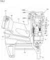
- FIG. 1 is an overall view depicting an example of a nailing machine of an embodiment
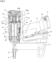
- FIGS. 2 and 3 are views of main parts depicting an example of the nailing machine of the embodiment and an operation example.
- a nailing machine 1A of the embodiment includes a main body part 10 and a handle part 11 extending from the main body part 10 and configured to be gripped by a hand.
- the nailing machine 1A includes a nose part 12 provided at one side of the main body part 10 and configured to strike out a fastener therefrom.
- the side at which the nose part 12 is provided is referred to as ⁇ lower side'.
- the nailing machine 1A includes a tank mounting part 13, to which a fuel tank (not shown) having fuel filled therein is detachably mounted and which is provided substantially in parallel with the handle part 11 below the handle part. Also, the nailing machine 1A includes a magazine 14 configured to share fasteners with the nose part 12 and provided below the tank mounting part 13. Also, the nailing machine 1A includes an air plug 15 to which an air hose, to which compressed air that is compressed oxidant is to be supplied from a supply source such as an air compressor, is connected and which is provided to the tank mounting part 13, in the embodiment.
- a supply source such as an air compressor
- the nailing machine 1A includes an operation trigger 16 configured to actuate the nailing machine 1A and provided to the handle part 11.
- a battery 17 which is a power supply of the nailing machine 1A is mounted to a battery mounting part 18.
- the battery mounting part is provided to the handle part 11.
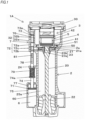
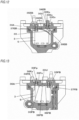
- the nailing machine 1A includes a striking cylinder 2 configured to be actuated by a combustion pressure of a mixed gas of compressed air and fuel, a combustion chamber 3 in which the mixed gas of compressed air and fuel is to be combusted, a head valve 4 configured to open and close communication between the striking cylinder 2 and the combustion chamber 3, and a valve support member 5 configured to support the head valve 4.
- the striking cylinder 2 is an example of the striking mechanism, and includes a driver 20 configured to strike out a fastener supplied from the magazine 14 to the nose part 12 and a piston 21 to which the driver 20 is provided.
- the striking cylinder 2 has a cylindrical space in which the piston 21 can be slid, and is configured so that the driver 20 is to move along the extension direction of the nose part 12 by a reciprocal operation of the piston 21.
- the striking cylinder 2 has a piston position restraint part 2a provided at a peripheral edge of an upper end and formed to have a tapered shape of which a diameter increases upward.
- a piston ring 21a provided on an outer peripheral surface of the piston 21 is engaged to the piston position restraint part 2a, so that a top dead point position of the piston 21 is defined.
- the engagement of the piston 21 with the piston position restraint part 2a is released by a force of pushing the piston 21 by a combustion pressure, so that the piston 21 can move by the combustion pressure.
- the striking cylinder 2 includes a buffer material 22 with which the piston 21 is to collide.
- the buffer material 22 is configured by an elastic member and is provided at a lower part of the striking cylinder 2.
- the piston 21 having moved by an operation of striking out a fastener collides with the buffer material 22, so that movement ranges of the driver 20 and the piston 21 are restrained.
- the combustion chamber 3 is provided above the striking cylinder 2 along axial directions of the driver 20 and the piston 21, which are an axial direction of the striking cylinder 2.
- the striking cylinder 2 and the combustion chamber 3 are partitioned by a partitioning part 50, and the partitioning part 50 is provided with a striking cylinder inlet 51 through which high temperature and high pressure combusted air is to pass.
- the striking cylinder inlet 51 is an example of the striking mechanism inlet, and is configured by forming a circular opening on axes of the driver 20 and the piston 21, which are the axial direction of the striking cylinder 2.
- the combustion chamber 3 has the valve support member 5 provided around the striking cylinder inlet 51, and a ring-shaped space formed around the valve support member 5. Therefore, the combustion chamber 3 is arranged radially outside of the valve support member 5 and the head valve 4.
- the head valve 4 is an example of the valve member, and is configured by a cylindrical metal member. As shown in FIGS. 6 and 7 , the head valve 4 has a circular planar valve surface 40 of which a lower end face in an axial direction of the cylinder is closed. The head valve 4 has a configuration where a diameter of the valve surface 40 is larger than the striking cylinder inlet 51. The striking cylinder inlet 51 is closed in a state where the valve surface 40 is in contact with the partitioning part 50.
- the head valve 4 has a first seal part 41 and a second seal part 42.
- the first seal part 41 is an example of the seal part, is provided on an outer periphery of the valve surface 40 in the axial direction, which is a moving direction of the head valve 4, and is attached with a first seal material 41a.
- the first seal material 41a is configured by a metal ring referred to as a piston ring.
- the first seal part 41 has a circumferential groove in which the first seal material 41a is fitted. When the first seal material 41a is attached to the first seal part, the first seal material 41a protrudes from a circumferential surface by a predetermined amount. In the case of the first seal part 41 of the embodiment, the two first seal materials 41a are attached along the axial direction of the head valve 4.
- the second seal part 42 is an example of the seal part, is provided on the outer periphery of the head valve 4 with being spaced from the first seal part 41 by a predetermined distance along the axial direction of the head valve 4, and is attached with a second seal material 42a.
- the second seal material 42a is a so-called O-ring made of an elastic body such as rubber.
- the second seal part 42 has a circumferential groove in which the second seal material 42a is fitted. When the second seal material 42a is attached to the second seal part, the second seal material 42a protrudes from a circumferential surface by a predetermined amount.
- the head valve 4 has a configuration where the first seal part 41 and the second seal part 42 protrude outward from the circumferential surface of the head valve 4 and a diameter of the second seal part 42 is larger than a diameter of the first seal part 41.
- the second seal part 42 has an actuation surface 43 that is a surface facing the first seal part 41 and is to be pushed by a high temperature and high pressure gas.
- the actuation surface 43 is a ring-shaped surface.
- the head valve 4 is configured to be urged in a direction of the partitioning part 50 by a spring 44.
- the spring 44 is an example of the urging member, and is configured by a coil spring.
- An axis of the spring 44 is provided on the axes of the driver 20 and the piston 21, which are on the axis of the striking cylinder 2, i.e., is provided coaxially with the head valve 4 and the striking cylinder inlet 51.
- the spring 44 is introduced into a concave part 45 having an open upper and formed in the head valve 4 along the axial direction, which is a moving direction of the head valve 4, so that the head valve 4 and a part of the spring 44 are arranged so as to overlap each other. This arrangement is referred to as ⁇ overlap arrangement'.
- a diameter of the spring 44 is made to be smaller than the head valve 4 and the striking cylinder 2.
- a force of pushing the head valve 4 by the spring 44 is a force of keeping a contact state of the valve surface 40 with the partitioning part 50 in a state where the high temperature and high pressure gas is not applied to the actuation surface 43.
- the head valve 4 is supported to be moveable by the valve support member 5.
- the valve support member 5 is an example of the valve support member and is configured by a cylindrical metal member. As shown in FIGS. 6 and 7 , in the embodiment, the valve support member 5 has the partitioning part 50 integrally provided at an axial lower part of the cylinder. When the head valve 4 is put in the cylindrical inner space, the first seal material 41a of the first seal part 41 and the second seal material 42a of the second seal part 42 of the head valve 4 are sliding contacted to the valve support member 5.
- the valve support member 5 has different inner diameters at parts to which the first seal material 41a of the first seal part 41 and the second seal material 42a of the second seal part 42 of the head valve 4 are sliding contacted, in conformity to the respective seal parts.
- an actuation space 52 is formed between the first seal part 41 and second seal part 42 of the head valve 4 and an inner surface of the valve support member 5.
- the actuation space 52 is an annular space.
- the valve support member 5 has a head valve inlet (valve member inlet) 53 for connecting the combustion chamber 3 and the actuation space 52.
- the head valve inlet 53 is configured by providing an opening penetrating the valve support member 5 in the vicinity of the first seal part 41 in a state where the valve surface 40 of the head valve 4 is in contact with the partitioning part 50.
- the head valve inlet 53 is formed on a side surface of the valve support member 5, so that a flow path connecting the combustion chamber 3 and the actuation space 52 becomes simple and an increase in inflow resistance can be prevented.
- the head valve inlet 53 is coupled to the actuation space 52 in the state where the valve surface 40 of the head valve 4 is in contact with the partitioning part 50, i.e., in the state where the striking cylinder inlet 51 is closed by the head valve 4.
- the air to pass through the head valve inlet 53 is the high temperature and high pressure air generated by combusting the mixed gas of compressed air and fuel in the combustion chamber 3. Since the high temperature and high pressure gas has lower viscosity than the ordinary temperature and pressure air, the increase in resistance against the gas flow is suppressed even though an opening area of the head valve inlet 53 is small.
- the first seal part 41 has the first seal material 41a provided on the outer periphery thereof, and the first seal material 41a is in contact with the inner surface of the valve support member 5. Since the first seal material 41a is fitted in the groove, a part to be exposed to the actuation space 52 is suppressed to the minimum.
- the second seal part 42 has the second seal material 42a provided on the outer periphery thereof, and the second seal material 42a is in contact with the inner surface of the valve support member 5. Since the second seal material 42a is fitted in the groove, a part to be exposed to the actuation space 52 is suppressed to the minimum.
- the valve support member 5 has a buffer material 54 with which the head valve 4 is to collide.
- the buffer material 54 is configured by an elastic member and is provided at an upper part of the head valve 4.
- the head valve 4 having moved due to the high temperature and high pressure gas applied to the actuation surface 43 of the head valve 4 collides with the buffer material 54 of the valve support member 5, so that a movement range of the head valve 4 is restrained.
- a height of the head valve inlet 53 is preferably set to be equal to or smaller than a stroke of the head valve 4.
- the upper opening of the combustion chamber 3 is sealed by a head part 30.
- the head part 30 is provided with an ignition device 31.
- the head part 30 is provided with a fuel supply port and a compressed air supply port (not shown).
- the buffer material 54 is provided to be in contact with the head part 30, so that the shock to be applied to the head part 30 is buffered, durability of a component is improved, a bolt for fastening the head part 30 to the combustion chamber 3 is prevented from being unfastened, and an electric noise is reduced.
- FIG. 8 is a perspective view depicting a first embodiment of the head part
- FIG. 9 is a top view of the head part of the first embodiment and the combustion chamber
- FIG. 10 is a sectional view of the head part of the first embodiment and the combustion chamber.
- FIG. 11 is a sectional view taken along a line A-A of FIG. 9
- FIG. 12 is a sectional view taken along a line B-B of FIG. 9
- FIG. 13 is a sectional view taken along a line C-C of FIG. 9 .
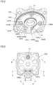
- a head part 30A which is the first embodiment of the head part 30, is provided with an ignition device 31. Also, the head part 30A is provided with a fuel supply port 30Fe to which the fuel is to be supplied and an air supply port 30Ea to which the compressed air is to be supplied. The head part 30A has the fuel supply port 30Fe and the air supply port 30Ea provided in parallel with each other.
- the fuel supply port 30Fe is configured by providing an opening to penetrate a top surface 30U, which is an inner wall surface of the head part 30A facing the combustion chamber 3, and is attached with a fuel pipe conduit connection member 30Fp to which a fuel pipe conduit 30Fi shown in FIG. 2 is to be connected.
- the air supply port 30Ea is an example of the oxidant supply port, is configured by providing an opening to penetrate the top surface 30U of the head part 30A, and is attached with an air pipe conduit connection member 30Ep to which an air pipe conduit 30Ei shown in FIGS. 2 and 3 is to be connected.
- the head part 30A has a fuel-side lead valve 30FB configured to suppress back-flow of flame, gas and the like from the combustion chamber 3 to the fuel supply port 30Fe and an air-side lead valve 30EB configured to suppress back-flow of flame, gas and the like from the combustion chamber 3 to the air supply port 30Ea. Also, the head part 30A has an air stirring part 33 configured to change an outflow direction of the compressed air to be supplied from the air supply port 30Ea.
- the fuel-side lead valve 30FB is an example of the check valve, is configured by an elastic metal plate, and has a valve part 34FB configured to open/close the fuel supply port 30Fe, a fixed part 35FB to be fixed to the head part 30A, and an elastic part 36FB configured to couple the valve part 34FB and the fixed part 35FB,
- the fuel-side lead valve 30FB has such a shape that the valve part 34FB is to cover the entire fuel supply port 30Fe. Also, the fixed part 35FB of the fuel-side lead valve 30FB, which is distant from the fuel supply port 30Fe at which the valve part 34FB covers the fuel supply port 30Fe, is fixed to the top surface 30U of the head part 30A by a screw 37FB.
- the head part 30A is formed on the top surface 30U of a peripheral edge of the fuel supply port 30Fe with a seal part 30Fs that is in contact with the valve part 34FB of the fuel-side lead valve 30FB.
- the fuel-side lead valve 30FB is moved in a direction in which the valve part 34FB is connected/separated to/from the seal part 30Fs as the elastic part 36FB is elastically deformed, thereby opening/closing the fuel supply port 30Fe.
- the fuel-side lead valve 30FB has an urging part 38FB configured to urge the valve part 34FB in a direction of the seal part 30Fs.
- the urging part 38FB is configured by providing a bent part having a predetermined shape to the elastic part 36FB, and is configured to suppress the valve part 34B from floating from the seal part 30Fs in a state where the fuel supply port 30Fe is closed with the valve part 34B by the elasticity of the elastic part 36B.
- the air-side lead valve 30EB is an example of the check valve, is configured by an elastic metal plate, and has a valve part 34EB configured to open/close the air supply port 30Ea, a fixed part 35EB to be fixed to the head part 30A, and an elastic part 36EB configured to couple the valve part 34EB and the fixed part 35EB.
- the air-side lead valve 30EB has the fixed part 35EB provided at a side distant from the fuel supply port 30Fe with respect to the arrangement of the fuel supply port 30Fe and the air supply port 30Ea, and the valve part 34EB configured to open/close the air supply port 30Ea and provided between the fixed part 35EB and fuel supply port 30Fe.
- the air-side lead valve 30EB has such a shape that the valve part 34EB is to cover the entire air supply port 30Ea. Also, the fixed part 35EB of the air-side lead valve 30EB, which is distant from the air supply port 30Ea at which the valve part 34EB covers the air supply port 30Ea, is fixed to the top surface 30U of the head part 30A by a screw 37EB, together with the air stirring part 33.
- the head part 30A is formed on the top surface 30U of a peripheral edge of the air supply port 30Ea with a seal part 30Es that is in contact with the valve part 34EB of the air-side lead valve 30EB.
- the air-side lead valve 30EB is moved in a direction in which the valve part 34EB is connected/separated to/from the seal part 30Es as the elastic part 36EB is elastically deformed, thereby opening/closing the air supply port 30Ea.
- the air stirring part 33 is an example of the stirring part, is configured by a metal plate having predetermined stiffness capable of suppressing deformation, which is caused due to a pressure of the compressed air to be supplied from the air supply port 30Ea and a combustion pressure in the combustion chamber 3, extends along an inner peripheral surface of the combustion chamber 3, and has a shape covering the air-side lead valve 30EB.
- a side of the air stirring part 33 distant from the fuel supply port 30Fe sandwiches the fixed part 35EB of the air-side lead valve 30EB between the side and the top surface 30U, and is fixed to the top surface 30U by the screw 37EB.
- the air stirring part 33 has such a shape that is curved in a direction in which an interval from the top surface 30U increases from the side fixed to the top surface 30U toward a tip end-side facing the valve part 34B of the air-side lead valve 30EB, and a part between the tip end-side of the air stirring part 33 and the air supply port 30Ea to be opened/closed by the air-side lead valve 30EB opens toward the fuel supply port 30Fe.
- the air stirring part 33 has a space, in which the air-side lead valve 30EB can be elastically deformed, provided between the air stirring part and the top surface 30U. Also, the air stirring part 33 has a curved surface, which faces the air-side lead valve 30EB and with which the elastically deformed air-side lead valve 30EB can be in contact.
- the air stirring part 33 has one side part, which faces the inner peripheral surface of the combustion chamber 3 and has a circular arc shape conforming to the inner peripheral surface of the combustion chamber 3.
- the air stirring part 33 stirs the compressed air, which is supplied from the air supply port 30Ea as the air-side lead valve 30EB is opened, and generates a flow of the air to rotate with swirling in a spiral shape along the inner peripheral surface of the combustion chamber 3. Also, the part between the tip end-side of the air stirring part 33 and the air supply port 30Ea is opened toward the fuel supply port 30Fe, so that the compressed air supplied from the air supply port 30Ea flows toward the fuel supply port 30Fe.
- the nailing machine 1A includes a blowback chamber 6 for collecting the gas to return the driver 20 and the piston 21 of the striking cylinder 2.
- the blowback chamber 6 is provided around the striking cylinder 2 and is coupled to an inside of the striking cylinder 2 at an inlet/outlet 60 provided in the vicinity of the buffer material 22.
- the nailing machine 1A has an exhaust valve 7 configured to exhaust the gas in the striking cylinder 2 and the combustion chamber 3.
- the exhaust valve 7 is provided at one side part of the striking cylinder 2 with respect to the extension direction of the handle part 11, and includes an exhaust piston 71 configured to be pushed by a gas introduced into the blowback chamber 6, a first exhaust valve 72 configured to open/close a striking cylinder exhaust port 23 formed in the striking cylinder 2, a second exhaust valve 73 configured to open/close a combustion chamber exhaust port 32 formed in the combustion chamber 3, and a valve rod 74 coupling the exhaust piston 71, the first exhaust valve 72 and the second exhaust valve 73.
- the exhaust piston 71, the first exhaust valve 72, the second exhaust valve 73, and the valve rod 74 of the exhaust valve 7 are integrally made of metal.
- the exhaust valve 7 is configured so that movement of the exhaust piston 71 is to be transmitted to the first exhaust valve 72 and the second exhaust valve 73 via the valve rod 74 and the first exhaust valve 72 and the second exhaust valve 73 are thus to move in conjunction with the movement.
- the exhaust valve 7 includes an exhaust cylinder 75 to be coupled to the blowback chamber 6, and an exhaust flow path forming cylinder 76 to be coupled to the striking cylinder exhaust port 23 and the combustion chamber exhaust port 32.
- the exhaust cylinder 75 has a cylindrical space, in which the exhaust piston 71 can be slid, provided at one side part of the striking cylinder 2 with respect to the extension direction of the handle part 11, and the exhaust valve 7 is configured to move in the extension direction of the valve rod 74 by a reciprocal operation of the exhaust piston 71.
- the exhaust flow path forming cylinder 76 has a cylindrical space, in which the first exhaust valve 72 and the second exhaust valve 73 can be slid, provided at one side part of the striking cylinder 2 with respect to the extension direction of the handle part 11, and extends in a moving direction of the piston 21.
- the striking cylinder exhaust port 23 is formed by an outer opening 23a penetrating the exhaust flow path forming cylinder 76 and an outside and an inner opening 23b penetrating the exhaust flow path forming cylinder 76 and the striking cylinder 2, and is configured to communicate the outside and the inside of the striking cylinder 2 via the exhaust flow path forming cylinder 76.
- the inner opening 23b of the striking cylinder exhaust port 23 is provided to face a top dead point position of the piston 21 so that the gas in the striking cylinder 2 can be exhausted to the outside by a return operation of the piston 21 from a bottom dead point position to the top dead point position. Also, the outer opening 23a of the striking cylinder exhaust port 23 opens toward a side of the striking cylinder 2, and the outer opening 23a and the inner opening 23b are arranged on one line.
- the combustion chamber exhaust port 32 is formed by an outer opening 32a penetrating the exhaust flow path forming cylinder 76 and the outside and an inner opening 32b penetrating the exhaust flow path forming cylinder 76 and the combustion chamber 3, and is configured to communicate the outside and the inside of the combustion chamber 3 via the exhaust flow path forming cylinder 76.
- the outer opening 32a of the combustion chamber exhaust port 32 opens toward a side of the striking cylinder 2, and the outer opening 32a and the inner opening 32b are arranged with being vertically offset in the moving direction of the second exhaust valve 73.
- the first exhaust valve 72 has a substantially circular column shape conforming to an inner peripheral surface of the exhaust flow path forming cylinder 76, and has a pair of sealing parts 72a, 72b having diameters capable of slidably contacting the inner surface of the exhaust flow path forming cylinder 76 and a flow path forming part 72c provided between the pair of sealing parts 72a, 72b, having a substantially circular column shape of a diameter smaller than the sealing parts 72a, 72b and forming a space between the flow path forming part and the inner surface of the exhaust flow path forming cylinder 76.
- the second exhaust valve 73 has a substantially circular plate shape conforming to the inner peripheral surface of the exhaust flow path forming cylinder 76 and includes a sealing member 73a provided on an outer peripheral surface thereof.
- the sealing member 73a is configured by an O-ring, for example, and the sealing member 73a is configured to sliding contact the inner peripheral surface of the exhaust flow path forming cylinder 76.
- the first exhaust valve 72 has such a configuration that when the flow path forming part 72c is moved to a position facing the outer opening 23a and the inner opening 23b of the striking cylinder exhaust port 23, the outer opening 23a and the inner opening 23b of the striking cylinder exhaust port 23 communicate with each other by the space formed between the inner surface of the exhaust flow path forming cylinder 76 and the flow path forming part 72c and the striking cylinder exhaust port 23 opens.
- the upper exhaust flow path forming cylinder 76 of the flow path forming part 72c is sealed by one sealing part 72a and the lower exhaust flow path forming cylinder 76 is sealed by the other sealing part 72b.
- the sealing parts 72a, 72b are made of metal and are not provided with a sealing member such as an O-ring but implement a sealing structure by dimensions of outer diameters of the sealing parts 72a, 72b and an inner diameter of the exhaust flow path forming cylinder 76.
- the second exhaust valve 73 moves to the upper of the inner opening 32b of the combustion chamber exhaust port 32, so that the inner opening 32b and the outer opening 32a of the combustion chamber exhaust port 32 communicate with each other therebetween by the exhaust flow path forming cylinder 76 and the combustion chamber exhaust port 32 opens, as shown in FIG. 1 .
- the sealing part 72a of the first exhaust valve 72 is located below the outer opening 32a of the combustion chamber exhaust port 32, so that the striking cylinder exhaust port 23 and the combustion chamber exhaust port 32 are sealed therebetween by the sealing part 72a of the first exhaust valve 72.
- the exhaust valve is configured by the first exhaust valve 72, the striking cylinder exhaust port 23 and the exhaust flow path forming cylinder 76
- the combustion chamber exhaust valve is configured by the second exhaust valve 73, the combustion chamber exhaust port 32 and the exhaust flow path forming cylinder 76.
- first exhaust valve 72, the striking cylinder exhaust port 23 and the exhaust flow path forming cylinder 76 are provided at one side part of the striking cylinder 2, and the striking cylinder exhaust port 23 faces toward a side of the striking cylinder 2.
- second exhaust valve 73, the combustion chamber exhaust port 32 and the exhaust flow path forming cylinder 76 are provided at one side part of the combustion chamber 3, and the combustion chamber exhaust port 32 faces toward a side of the combustion chamber 3.
- the exhaust valve 7 has a buffer material 77 with which the exhaust piston 71 is to collide.
- the buffer material 77 is configured by an elastic member.
- the exhaust piston 71 collides with the buffer material 77, so that a movement range of the exhaust valve 7 is restrained.
- the exhaust valve 7 includes a spring 79 configured to urge the valve rod 74 in a direction in which the first exhaust valve 72 is to close the striking cylinder exhaust port 23 and the second exhaust valve 73 is to close the combustion chamber exhaust port 32.
- the spring 79 is an example of the urging member, is configured by a compression coil spring, in the embodiment, and is interposed between a spring receiving part 24 provided on a side surface of the striking cylinder 2 and a spring retainer 74a attached to the valve rod 74.
- the spring retainer 74a is configured to move integrally with the valve rod 74.
- the first exhaust valve 72 opens the striking cylinder exhaust port 23 and the second exhaust valve 73 opens the combustion chamber exhaust port 32.
- the first exhaust valve 72 closes the striking cylinder exhaust port 23 and the second exhaust valve 73 closes the combustion chamber exhaust port 32.
- the nailing machine 1A has a contact member 8 provided in the nose part 12.
- the contact member 8 is provided to be moveable along the extension direction of the nose part 12, and is urged by a spring 80 in a direction in which it is to protrude from the nose part 12.
- the contact member 8 is coupled to the exhaust valve 7 via a link 81.
- the link 81 is attached to a side surface of the striking cylinder 2 to be rotatable about a shaft 81d, which is a support point, and is coupled at one end to the contact member 8.
- the link 81 is urged by the spring 80 such as a tensile coil spring, so that the contact member 8 rotates in the direction in which it protrudes from the nose part 12.
- the other end of the link 81 is coupled to the exhaust valve 7 via a long hole portion 78 formed in the valve rod 74.
- the long hole portion 78 is an opening extending in the moving direction of the valve rod 74 and is configured so that the valve rod 74 can move in a state where a position of the link 81 is fixed by the contact member 8.
- the link 81 rotates in conjunction with movement of the contact member 8, so that the exhaust valve 7 is actuated. Also, in the state where a position of the link 81 is fixed by the contact member 8, the link 81 and the valve rod 74 are decoupled with shapes of the link 81 and of the long hole portion 78 and the exhaust valve 7 is actuated by the gas introduced into the blowback chamber 6.
- the operation trigger 16 is not pulled, and the contact member 8 is not pressed to a material to be struck and is located at an initial position at which it is urged by the spring 80 and protrudes from the nose part 12.
- the link 81 is urged by the spring 80 to push the long hole portion 78 of the valve rod 74, so that the valve rod 74 is moved in the direction of compressing the spring 79.
- the flow path forming part 72c of the first exhaust valve 72 of the exhaust valve 7 is moved to the position facing the outer opening 23a and the inner opening 23b of the striking cylinder exhaust port 23, so that the striking cylinder exhaust port 23 is opened.
- the second exhaust valve 73 is moved to the upper side of the inner opening 32b of the combustion chamber exhaust port 32 in conjunction with the first exhaust valve 72, so that the inner opening 32b and the outer opening 32a of the combustion chamber exhaust port 32 communicate with each other therebetween by the exhaust flow path forming cylinder 76 and the combustion chamber exhaust port 32 is opened. Thereby, the striking cylinder 2 and the combustion chamber 3 are opened to the atmosphere.
- the head valve 4 is pressed by the spring 44 and is thus in the state where the valve surface 40 is in contact with the partitioning part 50, i.e., in the state where the striking cylinder inlet 51 is closed by the head valve 4. In this state, the head valve inlet 53 is connected to the actuation space 52.
- the link 81 When the contact member 8 is pressed to a material to be struck, the link 81 is rotated in a direction of extending the spring 80, so that the valve rod 74 is moved in the extension direction of the spring 79 in conformity to the rotation of the link 81 and the movement of the contact member 8 is transmitted to the exhaust valve 7 by the link 81.
- the air valve 30EV and the fuel valve 30FV are opened in conjunction with the contact member 8 and an operation of the operation trigger 16, so that the gasified fuel and the compressed air are supplied to the combustion chamber 3.
- the fuel valve 30FV is opened, and when the operation trigger 16 is operated, the air valve 30EV is opened.
- the air valve 30EV and fuel valve 30FV may be opened at predetermined timings.
- the air valve 30EV and fuel valve 30FV may be opened at predetermined timings.
- the valve part 34EB of the air-side lead valve 30EB is pushed by a pressure of the compressed air and the valve part 34EB is elastically deformed in a direction of separating from the seal part 30Es, so that the air supply port 30Ea is opened.
- the compressed air is supplied from the air supply port 30Ea to the combustion chamber 3, it is stirred by the air stirring part 33, so that a flow of air to rotate with swirling in a spiral shape along the inner peripheral surface of the combustion chamber 3 is generated.
- the part between the tip end-side of the air stirring part 33 and the air supply port 30Ea is opened toward the fuel supply port 30Fe, so that the compressed air supplied from the air supply port 30Ea flows toward the fuel supply port 30Fe.
- a degree of opening of the air-side lead valve 30EB is restrained by the air stirring part 33, and an amount of deformation of the elastic part 36EB is suppressed from increasing and the plastic deformation is suppressed while securing a necessary degree of opening of the air-side lead valve 30EB.
- valve part 34FB of the fuel-side lead valve 30FB When the fuel is supplied to the fuel supply port 30Fe, the valve part 34FB of the fuel-side lead valve 30FB is pushed by the pressure of the fuel and the valve part 34FB is elastically deformed in the direction of separating from the seal part 30Fs, so that the fuel supply port 30Fe is opened.
- the fuel When the fuel is supplied from the fuel supply port 30Fe to the combustion chamber 3, it is supplied from the air supply port 30Ea to the combustion chamber 3 and is mixed with compressed air stirred by the air stirring part 33, so that the mixed gas of the compressed air and fuel is filled in the combustion chamber 3.
- the contact member 8 is pressed to the material to be struck and the operation trigger 16 is operated, so that the air valve 30EV and fuel valve 30FV are opened and the air-side lead valve 30EB are opened. Thereby, the compressed air is supplied from the air supply port 30Ea, and the fuel-side lead valve 30FB is opened, so that the fuel is supplied from the fuel supply port 30Fe. Thereafter, when the ignition device 31 is actuated at a predetermined timing at which the air-side lead valve 30EB is closed and the fuel-side lead valve 30FB is closed, the mixed gas of compressed air and fuel in the combustion chamber 3 is combusted. When the mixed gas is combusted in the combustion chamber 3, the pressure in the combustion chamber 3 rises.
- the high temperature and high pressure gas is introduced from the head valve inlet 53 of the valve support member 5 into the actuation space 52, and the pressure in the actuation space 52 rises, the high temperature and high pressure gas is applied to the actuation surface 43 of the head valve 4, so that the head valve 4 is moved upward with compressing the spring 44.
- the pressure in the actuation space 52 rises, the pressure is applied to the surface of the first seal part 41 facing the actuation space 52, too.
- an area of the actuation surface 43 is larger than the area of the surface of the first seal part 41 facing the actuation space 52, the head valve 4 is moved upward with compressing the spring 44.
- the first exhaust valve 72 is moved to the position at which the flow path forming part 72c faces the outer opening 23a and the inner opening 23b of the striking cylinder exhaust port 23, so that the striking cylinder exhaust port 23 is opened.
- the second exhaust valve 73 is moved to the upper side of the inner opening 32b of the combustion chamber exhaust port 32 in conjunction with the first exhaust valve 72, so that the inner opening 32b and the outer opening 32a of the combustion chamber exhaust port 32 communicate with each other therebetween by the exhaust flow path forming cylinder 76 and the combustion chamber exhaust port 32 is opened.
- the striking cylinder 2 and the combustion chamber 3 are opened to the atmosphere, and the gas in the combustion chamber 3 is exhausted from the combustion chamber exhaust port 32 to the outside. Also, the pressure in the combustion chamber 3 is lowered, so that the head valve 4 is pressed with the spring 44 and is moved to the position at which the valve surface 40 is in contact with the partitioning part 50, and the striking cylinder inlet 51 is closed by the head valve 4.
- the piston 21 and the driver 20 When the piston 21 and the driver 20 are further moved in the direction of striking out a fastener and the piston 21 is moved to a bottom dead point and collides with the buffer material 22, the piston 21 and the driver 20 intend to move upward by the elasticity of the buffer material 22.
- the piston 21 moves to the upper of the inlet/outlet 60 through the inlet/outlet 60, the gas (air) in the blowback chamber 6 in which the pressure has risen is introduced into the striking cylinder 2 and pushes the piston 21.
- the piston 21 When the piston 21 is pushed, the air in the piston upper chamber 25b, which is the other chamber in the striking cylinder 2 partitioned by the piston 21, is exhausted from the striking cylinder exhaust port 23 to the outside, and the piston 21 and the driver 20 are returned to the top dead point.
- the compressed air and the fuel are supplied to the combustion chamber 3, the mixed gas is combusted to generate the high pressure gas, and the piston 21 of the striking cylinder 2 is pushed by the high pressure gas, so that the force of pushing the fastener by the piston 21 and the driver 20 increases.
- the head valve 4 configured to open and close the striking cylinder inlet 51 between the combustion chamber 3 and the striking cylinder 2 is provided, so that it is possible to disable the striking cylinder 2 from actuating even though the compressed air is just supplied to the combustion chamber 3. Also, the head valve 4 is actuated by the combustion pressure of the mixed gas, so that it is not necessary to provide a separate drive source for driving the head valve 4. Thereby, it is possible to simplify structures of the head valve 4 and the drive mechanism thereof, to miniaturize the device and to save the cost.
- the combustion chamber 3 is provided above the striking cylinder 2 along the axial direction of the driver 20 and the piston 21, so that it is possible to reduce the diameter of the combustion chamber 3 without reducing a volume of the combustion chamber 3, as compared to a structure where the combustion chamber is provided around the striking cylinder 2. Since the inside of the combustion chamber 3 is at the high pressure, it is necessary to make the combustion chamber 3 have predetermined strength. However, the diameter or the combustion chamber 3 can be made small, so that it is possible to secure the strength even when the combustion chamber 3 is made thin, and to implement miniaturization and weight saving of the entire device.
- the striking cylinder inlet 51 connecting the combustion chamber 3 and the striking cylinder 2 is provided on the axes of the driver 20 and the piston 21, so that it is possible to make the diameter of the striking cylinder inlet 51 smaller than the striking cylinder 2.
- the diameter of the head valve 4 can be made small, so that it is possible to improve the moving speed of the head valve 4 and to shorten the time necessary to open the striking cylinder inlet 51.
- the gas to actuate the head valve 4 is the high temperature and high pressure gas, the viscosity thereof is lower, as compared to a case where the ordinary pressure gas is combusted. Thereby, it is possible to reduce a diameter of the head valve inlet 53 through which the gas to actuate the head valve 4 is to pass, and to reduce a diameter of a surrounding structure of the combustion chamber 3 and the head valve 4.
- the first seal part 41 provided to the head valve 4 has the first seal material 41a provided on the outer periphery thereof, and the first seal material 41a is in contact with the inner surface of the valve support member 5. Since the first seal material 41a is fitted in the groove, the part to be exposed to the actuation space 52 is suppressed to the minimum. While the head valve 4 opens the striking cylinder inlet 51 and the head valve inlet 53, the high temperature and high pressure gas is introduced from the striking cylinder inlet 51 below the head valve 4. However, since the first seal material 41a is fitted in the groove, the part to be exposed is suppressed to the minimum.
- the high temperature and high pressure gas is applied to the actuation surface 43 of the head valve 4, so that while the head valve 4 moves and the head valve 4 opens the striking cylinder inlet 51 and the head valve inlet 53, the first seal part 41 passes by the head valve inlet 53 and the first seal material 41a is thus exposed to the high temperature and high pressure gas.
- the first seal material 41a is made of metal, the first seal material 41a is suppressed from being influenced by heat.
- the second seal part 42 has the second seal material 42a provided on the outer periphery thereof, and the second seal material 42a is in contact with the inner surface of the valve support member 5. Since the second seal material 42a is fitted in the groove, the part to be exposed to the actuation space 52 is suppressed to the minimum.
- the high temperature and high pressure gas is applied to the actuation surface 43 of the head valve 4, so that while the head valve 4 moves and the head valve 4 opens the head valve inlet 53, the second seal material 42a is suppressed from being influenced by heat because the exposure of the second seal material 42a is suppressed. Also, while the head valve 4 moves and the head valve 4 opens the head valve inlet 53, since the second seal part 42 does not pass by the head valve inlet 53, the second seal material 42a is suppressed from being exposed to the high temperature and high pressure gas.
- one seal material (the first seal material 41a) of the head valve 4 is made of metal, so that the friction with the valve support member 5 is reduced and it is possible to reduce the diameter of the head valve 4 and to improve the moving speed of the head valve 4.
- the head valve 4 has the seal material made of metal. Therefore, even when the seal material is arranged on the end face along the moving direction of the head valve 4 and is exposed to the flow path of the gas, it is possible to improve the durability of the seal part.
- the spring 44 is arranged on the same axis of the head valve 4, which is a center of the head valve 4, so that it is possible to use the high-load spring without enlarging the main body part 10.
- the concave part 45 is formed in the axial direction of the head valve 4 and is overlap-arranged so that the spring 44 is to enter therein.
- the spring 44 is to enter the concave part 45 of the head valve 4, so that it is possible to suppress a size of the main body part 10 in a height direction from increasing. Also, since the spring 44 is to enter the concave part 45 of the head valve 4, the diameter of the spring 44 can be made smaller than the striking cylinder 2, so that it is possible to suppress a size of the main body part 10 in a radial direction from increasing.
- valve part 34EB of the air-side lead valve 30EB When the compressed air is supplied to the air supply port 30Ea, the valve part 34EB of the air-side lead valve 30EB is pushed by the pressure of the compressed air and the elastic part 36EB is elastically deformed in the direction in which the valve part 34EB separates from the seal part 30Es, so that the air supply port 30Ea is opened.
- the air-side lead valve 30EB is provided on the top surface 30U, and the air supply port 30Ea is not exposed to the combustion chamber 3 in the state where the air supply port 30Ea is closed by the valve part 34EB.
- the air pipe conduit 30Ei it is possible to suppress the flame and the like, which are generated as the mixed gas in the combustion chamber 3 is combusted, from flowing back from the air supply port 30Ea to the air pipe conduit 30Ei, and to suppress damages of the air pipe conduit 30Ei and the air valve 30EV. Also, it is not necessary for the air pipe conduit 30Ei to have the pressure resistance performance corresponding to the combustion pressure, so that it is possible to lower the pressure resistance performance. Thereby, it is possible to use a flexible material and to suppress the damage, which is caused due to vibrations and the like upon the striking.
- the degree of opening of the air-side lead valve 30EB is restrained by the air stirring part 33, and the deformation amount of the air-side lead valve 30EB, which is to be deformed by the pressure of the compressed air, is suppressed from increasing, so that it is possible to suppress the air-side lead valve 30EB from being plastically deformed.
- the air stirring part 33 has the curved surface with which the elastically deformable air-side lead valve 30EB can be in contact. Therefore, even when the air-side lead valve 30EB, which is to be deformed by the pressure of the compressed air, is pressed to the air stirring part 33, it is possible to suppress the plastic deformation such as a fold line to be formed on the air-side lead valve 30EB.
- valve part 34FB of the fuel-side lead valve 30FB When the fuel is supplied to the fuel supply port 30Fe, the valve part 34FB of the fuel-side lead valve 30FB is pushed by the pressure of the fuel and the elastic part 36FB is elastically deformed in the direction in which the valve part 34FB is to separate from the seal part 30Fs, so that the fuel supply port 30Fe is opened.
- the fuel-side lead valve 30FB is provided on the top surface 30U, and the air fuel supply port 30Fe is not exposed to the combustion chamber 3 in the state where the fuel supply port 30Fe is closed by the valve part 34FB.
- the fuel pipe conduit 30Fi it is possible to suppress the flame and the like, which are generated as the mixed gas in the combustion chamber 3 is combusted, from flowing back from the fuel supply port 30Fe to the fuel pipe conduit 30Fi, and to suppress damages of the fuel pipe conduit 30Fi and the fuel valve 30FV. Also, it is not necessary for the fuel pipe conduit 30Fi to have the pressure resistance performance corresponding to the combustion pressure, so that it is possible to lower the pressure resistance performance. Thereby, it is possible to use a flexible material and to suppress the damage, which is caused due to vibrations and the like upon the striking. Also, even when the fuel remains in the fuel supply port 30Fe and the fuel pipe conduit 30Fi, the remaining fuel is suppressed from being imperfectly combusted and the soot is suppressed from being attached into the fuel pipe conduit 30Fi.
- an amount of the fuel to be supplied to the combustion chamber 3 is measured by a method of sending liquefied fuel to a small measurement chamber provided in the fuel valve 30FV and measuring the same by a volume. For this reason, when a gas is mixed in the measurement chamber, it is not possible to perform correct measurement, so that it is not possible to supply a prescribed amount of fuel. Also, in the case of a check valve for which a lead valve is adopted, a gap may be generated between the valve part and the seal part due to bending of the lead valve. The gap is generated between the valve part and the seal part, so that when the compressed air is mixed in the fuel pipe conduit 30Fi, it is not possible to normally supply the fuel because the pressure of the compressed air is higher than the supply pressure of the fuel.
- the fuel-side lead valve 30FB is provided with the urging part 38FB for urging the valve part 34FB in the direction of the seal part 30Fs, so that the force of pressing the valve part 34FB to the seal part 30Fs increases in the closed state of the fuel supply port 30Fe.
- the air-side lead valve 30EB is provided with the fixed part 35EB at the side distant from the fuel supply port 30Fe with respect to the arrangement of the fuel supply port 30Fe and the air supply port 30Ea and the side of air-side lead valve 30EB facing toward the fuel supply port 30Fe is opened. Therefore, the part between the tip end-side of the air stirring part 33 and the air supply port 30Ea is opened toward the fuel supply port 30Fe, so that the compressed air supplied from the air supply port 30Ea flows toward the fuel supply port 30Fe.
- FIG. 14 is a perspective view depicting a second embodiment of the head part.
- a head part 30B is provided with the ignition device 31. Also, the head part 30B is provided with the fuel supply port 30Fe to which the fuel is to be supplied and the air supply port 30Ea to which the compressed air is to be supplied.
- the head part 30B has the fuel supply port 30Fe and the air supply port 30Ea provided in parallel with each other.
- the head part 30B has the fuel-side lead valve 30FB configured to suppress back-flow of flame, gas and the like from the combustion chamber 3 to the fuel supply port 30Fe and the air-side lead valve 30EB configured to suppress back-flow of flame, gas and the like from the combustion chamber 3 to the air supply port 30Ea. Also, the head part 30B has the air stirring part 33 configured to stir the compressed air to be supplied from the air supply port 30Ea.
- the air-side lead valve 30EB and the air stirring part 33 of the head part 30B of the second embodiment have the same configurations as the head part 30A of the first embodiment, and the descriptions thereof are omitted.
- the elastic part 36FB of the fuel-side lead valve 30FB has a flat plate shape.
- the fuel-side lead valve 30FB includes an urging member 39FB for urging the valve part 34FB in the direction of the seal part 30Fs.
- the urging member 39FB is configured by an elastic metal plate and has a bent part having a predetermined shape.
- the urging member 39FB is fixed with the screw 37FB, together with the fuel-side lead valve 30FB, and is configured to push the valve part 34FB at a tip end-side thereof.
- the force of pressing the valve part 34FB to the seal part 30Fs increases in the closed state of the fuel supply port 30Fe, so that it is possible to suppress the fuel-side lead valve 30FB from vibrating, which is caused when the valve part 34FB is floated from the seal part 30Fs and the valve part 34FB is floated from the seal part 30Fs by the pressure of the compressed air stirred by the air stirring part 33, the combustion pressure and the like.
- FIG. 15 is a perspective view depicting a third embodiment of the head part.
- a head part 30C is provided with the ignition device 31. Also, the head part 30C is provided with the fuel supply port 30Fe to which the fuel is to be supplied and the air supply port 30Ea to which the compressed air is to be supplied.
- the head part 30C has the fuel supply port 30Fe and the air supply port 30Ea provided in parallel with each other.
- the head part 30C has the fuel-side lead valve 30FB configured to suppress back-flow of flame, gas and the like from the combustion chamber 3 to the fuel supply port 30Fe and the air-side lead valve 30EB configured to suppress back-flow of flame, gas and the like from the combustion chamber 3 to the air supply port 30Ea. Also, the head part 30C has the air stirring part 33 configured to stir the compressed air to be supplied from the air supply port 30Ea.
- the air-side lead valve 30EB and the air stirring part 33 of the head part 30C of the third embodiment have the same configurations as the head part 30A of the first embodiment, and the descriptions thereof are omitted.
- the elastic part 36FB of the fuel-side lead valve 30FB has a flat plate shape.
- the head part 30C has a shield part 33C provided at a side facing the air supply port 30Ea of the fuel supply port 30Fe and configured to shield a flow of the compressed air supplied from the air supply port 30Ea.
- the shield part 33C is configured by providing a convex part, which faces inward from an inner peripheral surface of the head part 30C and protrudes from the top surface 30U, between the air supply port 30Ea and fuel supply port 30Fe.
- the air which is supplied from the air supply port 30Ea as the air-side lead valve 30EB is opened, is shielded from flowing in the direction of the fuel supply port 30Fe along the top surface 30U by the shield part 33C, so that it is possible to suppress the valve part 34FB of the fuel-side lead valve 30FB from floating from the seal part 30Fs without providing the fuel-side lead valve 30FB with the urging part and without urging the fuel-side lead valve 30FB by the urging member.
- FIG. 16 is a perspective view depicting a fourth embodiment of the head part.
- a head part 30D is provided with the ignition device 31. Also, the head part 30D is provided with the fuel supply port 30Fe to which the fuel is to be supplied and the air supply port 30Ea to which the compressed air is to be supplied.
- the head part 30D has the fuel supply port 30Fe and the air supply port 30Ea provided in parallel with each other.
- the head part 30D has the fuel-side lead valve 30FB configured to suppress back-flow of flame, gas and the like from the combustion chamber 3 to the fuel supply port 30Fe and the air-side lead valve 30EB configured to suppress back-flow of flame, gas and the like from the combustion chamber 3 to the air supply port 30Ea. Also, the head part 30D has the air stirring part 33 configured to stir the compressed air to be supplied from the air supply port 30Ea.
- the air-side lead valve 30EB and the air stirring part 33 of the head part 30D of the fourth embodiment have the same configurations as the head part 30A of the first embodiment, and the descriptions thereof are omitted.
- the elastic part 36FB of the fuel-side lead valve 30FB has a flat plate shape.
- the head part 30D has a step part 30Dr, into which the fuel-side lead valve 30FB is to enter, provided on the top surface 30U.
- the step part 30Dr has substantially the same depth as a thickness of the fuel-side lead valve 30FB, and is configured by providing a concave part having a shape in which the fuel-side lead valve 30FB is to entirely enter, in the fourth embodiment, and a surface of the fuel-side lead valve 30FB facing the combustion chamber 3 and the top surface 30U arte substantially the same.
- the air which is supplied from the air supply port 30Ea as the air-side lead valve 30EB is opened and flows in the direction of the fuel supply port 30Fe along the top surface 30U, is suppressed from colliding between the valve part 34FB and the seal part 30Fs of the fuel-side lead valve 30FB, so that it is possible to suppress the valve part 34FB of the fuel-side lead valve 30FB from floating from the seal part 30Fs without providing the fuel-side lead valve 30FB with the urging part and without urging the fuel-side lead valve 30FB by the urging member.
- a step part into which the valve part 34FB, not the entire fuel-side lead valve 30FB, is to enter may be provided.
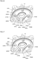
- FIG. 17 is a perspective view depicting a fifth embodiment of the head part.
- a head part 30E is provided with the ignition device 31. Also, the head part 30E is provided with the fuel supply port 30Fe to which the fuel is to be supplied and the air supply port 30Ea to which the compressed air is to be supplied.
- the head part 30E has the fuel supply port 30Fe provided at a position distant from the air supply port 30Ea.
- the head part 30E has the fuel-side lead valve 30FB configured to suppress back-flow of flame, gas and the like from the combustion chamber 3 to the fuel supply port 30Fe and the air-side lead valve 30EB configured to suppress back-flow of flame, gas and the like from the combustion chamber 3 to the air supply port 30Ea.
- the head part 30E has the air stirring part 33 configured to stir the compressed air to be supplied from the air supply port 30Ea.
- the air-side lead valve 30EB and the air stirring part 33 of the head part 30D of the fifth embodiment have the same configurations as the head part 30A of the first embodiment, and the descriptions thereof are omitted.
- the elastic part 36FB of the fuel-side lead valve 30FB has a flat plate shape.
- the fuel-side lead valve 30FB has the fixed part 35FB provided between the valve part 34FB configured to open/close the fuel supply port 30Fe and the air supply port 30Ea, and the fixed part 35EB is provided at a side close to the air supply port 30Ea with respect to the arrangement of the fuel supply port 30Fe and the air supply port 30Ea.
- the fixed part 35FB of the fuel-side lead valve 30FB which is arranged at a side close to the air supply port 30Ea at which the valve part 34FB covers the fuel supply port 30Fe, is fixed to the top surface 30U of the head part 30E by the screw 37FB.
- the fixed part 35FB of the fuel-side lead valve 30FB is arranged at an upstream side with respect to the flow of the compressed air, which is supplied from the air supply port 30Ea as the air-side lead valve 30EB is opened and is stirred to swirl by the air stirring part 33, and the valve part 34FB and the seal part 30Fs are arranged at a downstream side, so that it is possible to suppress the valve part 34FB from floating from the seal part 30Fs without providing the fuel-side lead valve 30FB with the urging part and without urging the fuel-side lead valve 30FB by the urging member.
- FIG. 18 is a perspective view depicting a sixth embodiment of the head part.
- a head part 30F is provided with the ignition device 31. Also, the head part 30F is provided with the fuel supply port 30Fe to which the fuel is to be supplied and the air supply port 30Ea to which the compressed air is to be supplied.
- the head part 30F has the fuel supply port 30Fe and the air supply port 30Ea provided in parallel with each other.
- the head part 30F has the air stirring part 33 configured to stir the compressed air that is to be supplied from the air supply port 30Ea.
- the air stirring part 33 is fixed to the top surface 30U by the screw 37EB at a side distant from the fuel supply port 30Fe.
- the air stirring part 33 has such a shape that it is curved in a direction in which an interval from the top surface 30U increases from the side fixed to the top surface 30U toward the tip end-side facing the air supply port 30Ea, and the part between the tip end-side of the air stirring part 33 and the air supply port 30Ea is opened toward the fuel supply port 30Fe. Also, one side part of the air stirring part 33, which faces the inner peripheral surface of the combustion chamber 3, has a circular arc shape conforming to the inner peripheral surface of the combustion chamber 3.
- the air stirring part 33 stirs the compressed air supplied from the air supply port 30Ea and generates a flow of the air to rotate with swirling in a spiral shape along the inner peripheral surface of the combustion chamber 3. Also, the part between the tip end-side of the air stirring part 33 and the air supply port 30Ea is opened toward the fuel supply port 30Fe, so that the compressed air supplied from the air supply port 30Ea flows toward the fuel supply port 30Fe.
- the compressed air is widely spread to involve the fuel supplied into the combustion chamber 3 over the entire combustion chamber 3, the mixing of the fuel and the compressed air is promoted and a distribution of the mixed gas is suppressed from being inclined to one side in the combustion chamber 3, so that it is possible to improve the combustion efficiency.
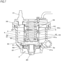
- FIG. 19 is a perspective view depicting a seventh embodiment of the head part.
- a head part 30G is provided with the ignition device 31. Also, the head part 30G is provided with the fuel supply port 30Fe to which the fuel is to be supplied and an air supply port nozzle 30En to which the compressed air is to be supplied.
- the head part 30G has the fuel supply port 30Fe and the air supply port nozzle 30En provided in parallel with each other.
- the air supply port nozzle 30En is an example of the stirring part, wherein a cylindrical member is erected from an air supply port (not shown) and at least one supply port 30Ee is provided on a circumferential surface.
- the air supply port nozzle 30En is provided so that the supply port 30Ee is to face toward the fuel supply port 30Fe.
- the compressed air is widely spread over the entire combustion chamber 3, the mixing of the fuel and the compressed air is promoted and a distribution of the mixed gas is suppressed from being inclined to one side in the combustion chamber 3, so that it is possible to improve the combustion efficiency.
- the respective embodiment may be combined.
- the second embodiment shown in FIG. 14 where the fuel-side lead valve 30FB is provided with the urging member 39FB may be provided with the shield part 33C of the third embodiment shown in FIG. 15 .
- the air-side lead valve 30EB and fuel-side lead valve 30FB are provided to the top surface 30U as the inner wall surface of the combustion chamber 3 but may be provided on an inner surface as the inner wall surface of the combustion chamber 3.
- the air is used as the oxidant, and the mixed gas of the compressed air as the compressed oxidant and the fuel is used for actuation.
- the oxidant is not limited to the compressed air and the other oxidants may be used inasmuch as the oxidant contains oxygen necessary for combustion of the fuel.
- oxygen, ozone, nitrogen monoxide and the like may also be used, instead of the air.
Landscapes
- Engineering & Computer Science (AREA)
- Chemical & Material Sciences (AREA)
- Combustion & Propulsion (AREA)
- Mechanical Engineering (AREA)
- Physics & Mathematics (AREA)
- Fluid Mechanics (AREA)
- General Engineering & Computer Science (AREA)
- Portable Nailing Machines And Staplers (AREA)
Description
- This application claims priorities from
Japanese patent applications No. 2018-7633 filed on January 19, 2018 No. 2018-7520 filed on January 19, 2018 No. 2018-7521 filed on January 19, 2018 No. 2018-22480 filed on February 9, 2018 No. 2018-22481 filed on February 9, 2018 No. 2018-22482 filed on February 9, 2018 No. 2018-26624 filed on February 19, 2018 No. 2018-84498 filed on April 25, 2018 No. 2018-84499 filed on April 25, 2018 No. 2018-84500 filed on April 25, 2018 No. 2018-84501 filed on April 25, 2018 - The present disclosure relates to a driving tool configured to combust a mixed gas of air and fuel and to be driven by a combustion pressure.
- A driving tool referred to as a nailing machine configured to strike a fastener such as a nail by actuating a piston with a striking cylinder by using a compressed air as a power source and driving a driver joined to the piston has been known. In the driving tool, a valve referred to as a head valve is configured so that the compressed air is to be supplied from a side of the striking cylinder.
- Also, a driving tool referred to as a nailing machine configured to strike a fastener such as a nail by combusting a mixed gas of air and fuel and actuating a striking cylinder by a combustion pressure has been known. In the gas combustion type driving tool, the mixed gas of which a pressure has been increased in advance is combusted to further increase the combustion pressure. However, since the mixed gas of which a pressure has been increased is generated, when the compressed air is supplied to a combustion chamber, the striking cylinder is actuated by a pressure of the compressed air before the mixed gas is combusted.
- Therefore, a driving tool including a valve configured to openably/closably partition a combustion chamber in which a mixed gas of compressed air and fuel is to be combusted and a striking cylinder has been suggested (for example, refer to Patent Document 1).
Patent Document 1:Japanese Patent No. 4,935,978B - In the related art, the same configuration as the driving tool in which the compressed air is used as a power source is used for the valve configured to openably/closably partition the combustion chamber and the striking cylinder, and the high temperature and high pressure combusted gas is supplied to the valve from a side of the striking cylinder.
- In the above configuration, a seal material is provided on an end face of the valve in a moving direction. However, in a state where the valve is opened, the seal material is exposed to a flow path of the gas. Since the gas which is obtained as a result of the combustion of the mixed gas of compressed air and fuel is at the high temperature and high pressure, when the seal material is exposed to the flow path of the gas, the durability of the seal material is deteriorated due to an influence of heat. Also, a spring configured to urge the valve in a closing direction is provided. However, in the configuration where the high temperature and high pressure combusted gas is supplied from a side of the striking cylinder, a diameter of the spring increases, which in turn increases a size of a main body.
GB 1 499 587 A US 3,850,359 A discloses a high pressure tool according to the preamble of claim 1, and including a combustion chamber and a cylinder. A main valve assembly is provided to control communication between the combustion chamber and the cylinder, wherein the valve assembly has an annular resilient valve member. - The present disclosure has been made in view of the above situations, and an object thereof is to provide a driving tool capable of improving durability of a seal part and suppressing a size of a main body from increasing.
- One aspect of the present disclosure is a driving tool as defined in claim 1 and comprising: a striking mechanism configured to be actuated by a combustion pressure of a mixed gas of compressed air and fuel; a combustion chamber in which the mixed gas of compressed air and fuel is to be combusted; a valve member configured to open and close communication between the striking mechanism and the combustion chamber; and a valve support member configured to support the valve member, wherein the valve member has a seal part provided on an outer peripheral surface along a moving direction of the valve member .
- According to the present disclosure, the seal part is provided on the outer periphery of the valve member configured to open and close communication between the striking mechanism and the combustion chamber, so that the seal part is suppressed from being exposed to a gas obtained as a result of combustion of a mixed gas of compressed air and fuel.
- According to the present disclosure, the mixed gas of compressed air and fuel is combusted, the striking mechanism is actuated by the combustion pressure, and the durability of the seal part can be improved.
-
-
FIG. 1 is a configuration view of main parts depicting an example of a nailing machine of an embodiment. -
FIG. 2 is an overall configuration view depicting an example of the nailing machine of the embodiment. -
FIG. 3 is an overall configuration view depicting an example of the nailing machine of the embodiment. -
FIG. 4 is a configuration view of main parts depicting an example of the nailing machine of the embodiment and an operation example. -
FIG. 5 is a configuration view of main parts depicting an example of the nailing machine of the embodiment and an operation example. -
FIG. 6 is a configuration view of main parts depicting an example of the nailing machine of the embodiment and an operation example. -
FIG. 7 is a configuration view of main parts depicting an example of the nailing machine of the embodiment and an operation example. -
FIG. 8 is a perspective view depicting a first embodiment of a head part. -
FIG. 9 is a top view of the head part of the first embodiment and a combustion chamber. -
FIG. 10 is a sectional view of the head part of the first embodiment and the combustion chamber. -
FIG. 11 is a sectional view taken along a line A-A ofFIG. 9 . -
FIG. 12 is a sectional view taken along a line B-B ofFIG. 9 . -
FIG. 13 is a sectional view taken along a line C-C ofFIG. 9 . -
FIG. 14 is a perspective view depicting a second embodiment of the head part. -
FIG. 15 is a perspective view depicting a third embodiment of the head part. -
FIG. 16 is a perspective view depicting a fourth embodiment of the head part. -
FIG. 17 is a perspective view depicting a fifth embodiment of the head part. -
FIG. 18 is a perspective view depicting a sixth embodiment of the head part. -
FIG. 19 is a perspective view depicting a seventh embodiment of the head part. - Hereinafter, an embodiment of a nailing machine, which is an example of the driving tool of the present disclosure, will be described with reference to the drawings.
-
FIG. 1 is an overall view depicting an example of a nailing machine of an embodiment, andFIGS. 2 and3 are views of main parts depicting an example of the nailing machine of the embodiment and an operation example. - A
nailing machine 1A of the embodiment includes amain body part 10 and ahandle part 11 extending from themain body part 10 and configured to be gripped by a hand. Thenailing machine 1A includes anose part 12 provided at one side of themain body part 10 and configured to strike out a fastener therefrom. In below descriptions, considering a using aspect of thenailing machine 1A, the side at which thenose part 12 is provided is referred to as `lower side'. - The
nailing machine 1A includes atank mounting part 13, to which a fuel tank (not shown) having fuel filled therein is detachably mounted and which is provided substantially in parallel with thehandle part 11 below the handle part. Also, thenailing machine 1A includes amagazine 14 configured to share fasteners with thenose part 12 and provided below thetank mounting part 13. Also, thenailing machine 1A includes anair plug 15 to which an air hose, to which compressed air that is compressed oxidant is to be supplied from a supply source such as an air compressor, is connected and which is provided to thetank mounting part 13, in the embodiment. - Also, the
nailing machine 1A includes anoperation trigger 16 configured to actuate thenailing machine 1A and provided to thehandle part 11. Abattery 17 which is a power supply of thenailing machine 1A is mounted to abattery mounting part 18. The battery mounting part is provided to thehandle part 11. - The
nailing machine 1A includes astriking cylinder 2 configured to be actuated by a combustion pressure of a mixed gas of compressed air and fuel, acombustion chamber 3 in which the mixed gas of compressed air and fuel is to be combusted, ahead valve 4 configured to open and close communication between thestriking cylinder 2 and thecombustion chamber 3, and avalve support member 5 configured to support thehead valve 4. - The
striking cylinder 2 is an example of the striking mechanism, and includes adriver 20 configured to strike out a fastener supplied from themagazine 14 to thenose part 12 and apiston 21 to which thedriver 20 is provided. Thestriking cylinder 2 has a cylindrical space in which thepiston 21 can be slid, and is configured so that thedriver 20 is to move along the extension direction of thenose part 12 by a reciprocal operation of thepiston 21. - The
striking cylinder 2 has a pistonposition restraint part 2a provided at a peripheral edge of an upper end and formed to have a tapered shape of which a diameter increases upward. When thepiston 21 is moved upward, apiston ring 21a provided on an outer peripheral surface of thepiston 21 is engaged to the pistonposition restraint part 2a, so that a top dead point position of thepiston 21 is defined. In the meantime, the engagement of thepiston 21 with the pistonposition restraint part 2a is released by a force of pushing thepiston 21 by a combustion pressure, so that thepiston 21 can move by the combustion pressure. - Also, the
striking cylinder 2 includes abuffer material 22 with which thepiston 21 is to collide. Thebuffer material 22 is configured by an elastic member and is provided at a lower part of thestriking cylinder 2. In thestriking cylinder 2, thepiston 21 having moved by an operation of striking out a fastener collides with thebuffer material 22, so that movement ranges of thedriver 20 and thepiston 21 are restrained. - The
combustion chamber 3 is provided above thestriking cylinder 2 along axial directions of thedriver 20 and thepiston 21, which are an axial direction of thestriking cylinder 2. Thestriking cylinder 2 and thecombustion chamber 3 are partitioned by apartitioning part 50, and thepartitioning part 50 is provided with astriking cylinder inlet 51 through which high temperature and high pressure combusted air is to pass. Thestriking cylinder inlet 51 is an example of the striking mechanism inlet, and is configured by forming a circular opening on axes of thedriver 20 and thepiston 21, which are the axial direction of thestriking cylinder 2. - The
combustion chamber 3 has thevalve support member 5 provided around thestriking cylinder inlet 51, and a ring-shaped space formed around thevalve support member 5. Therefore, thecombustion chamber 3 is arranged radially outside of thevalve support member 5 and thehead valve 4. - The
head valve 4 is an example of the valve member, and is configured by a cylindrical metal member. As shown inFIGS. 6 and7 , thehead valve 4 has a circularplanar valve surface 40 of which a lower end face in an axial direction of the cylinder is closed. Thehead valve 4 has a configuration where a diameter of thevalve surface 40 is larger than thestriking cylinder inlet 51. Thestriking cylinder inlet 51 is closed in a state where thevalve surface 40 is in contact with thepartitioning part 50. - The
head valve 4 has afirst seal part 41 and asecond seal part 42. Thefirst seal part 41 is an example of the seal part, is provided on an outer periphery of thevalve surface 40 in the axial direction, which is a moving direction of thehead valve 4, and is attached with afirst seal material 41a. Thefirst seal material 41a is configured by a metal ring referred to as a piston ring. Thefirst seal part 41 has a circumferential groove in which thefirst seal material 41a is fitted. When thefirst seal material 41a is attached to the first seal part, thefirst seal material 41a protrudes from a circumferential surface by a predetermined amount. In the case of thefirst seal part 41 of the embodiment, the twofirst seal materials 41a are attached along the axial direction of thehead valve 4. - The
second seal part 42 is an example of the seal part, is provided on the outer periphery of thehead valve 4 with being spaced from thefirst seal part 41 by a predetermined distance along the axial direction of thehead valve 4, and is attached with asecond seal material 42a. Thesecond seal material 42a is a so-called O-ring made of an elastic body such as rubber. Thesecond seal part 42 has a circumferential groove in which thesecond seal material 42a is fitted. When thesecond seal material 42a is attached to the second seal part, thesecond seal material 42a protrudes from a circumferential surface by a predetermined amount. - The
head valve 4 has a configuration where thefirst seal part 41 and thesecond seal part 42 protrude outward from the circumferential surface of thehead valve 4 and a diameter of thesecond seal part 42 is larger than a diameter of thefirst seal part 41. Thesecond seal part 42 has anactuation surface 43 that is a surface facing thefirst seal part 41 and is to be pushed by a high temperature and high pressure gas. Theactuation surface 43 is a ring-shaped surface. - The
head valve 4 is configured to be urged in a direction of thepartitioning part 50 by aspring 44. Thespring 44 is an example of the urging member, and is configured by a coil spring. An axis of thespring 44 is provided on the axes of thedriver 20 and thepiston 21, which are on the axis of thestriking cylinder 2, i.e., is provided coaxially with thehead valve 4 and thestriking cylinder inlet 51. Thespring 44 is introduced into aconcave part 45 having an open upper and formed in thehead valve 4 along the axial direction, which is a moving direction of thehead valve 4, so that thehead valve 4 and a part of thespring 44 are arranged so as to overlap each other. This arrangement is referred to as `overlap arrangement'. Also, in order for thespring 44 to be introduced into theconcave part 45 of thehead valve 4, a diameter of thespring 44 is made to be smaller than thehead valve 4 and thestriking cylinder 2. - A force of pushing the
head valve 4 by thespring 44 is a force of keeping a contact state of thevalve surface 40 with thepartitioning part 50 in a state where the high temperature and high pressure gas is not applied to theactuation surface 43. - The
head valve 4 is supported to be moveable by thevalve support member 5. - The
valve support member 5 is an example of the valve support member and is configured by a cylindrical metal member. As shown inFIGS. 6 and7 , in the embodiment, thevalve support member 5 has thepartitioning part 50 integrally provided at an axial lower part of the cylinder. When thehead valve 4 is put in the cylindrical inner space, thefirst seal material 41a of thefirst seal part 41 and thesecond seal material 42a of thesecond seal part 42 of thehead valve 4 are sliding contacted to thevalve support member 5. Thevalve support member 5 has different inner diameters at parts to which thefirst seal material 41a of thefirst seal part 41 and thesecond seal material 42a of thesecond seal part 42 of thehead valve 4 are sliding contacted, in conformity to the respective seal parts. - When the
head valve 4 is put in thevalve support member 5, anactuation space 52 is formed between thefirst seal part 41 andsecond seal part 42 of thehead valve 4 and an inner surface of thevalve support member 5. Theactuation space 52 is an annular space. - The
valve support member 5 has a head valve inlet (valve member inlet) 53 for connecting thecombustion chamber 3 and theactuation space 52. Thehead valve inlet 53 is configured by providing an opening penetrating thevalve support member 5 in the vicinity of thefirst seal part 41 in a state where thevalve surface 40 of thehead valve 4 is in contact with thepartitioning part 50. Thehead valve inlet 53 is formed on a side surface of thevalve support member 5, so that a flow path connecting thecombustion chamber 3 and theactuation space 52 becomes simple and an increase in inflow resistance can be prevented. - As shown in
FIG. 6 , thehead valve inlet 53 is coupled to theactuation space 52 in the state where thevalve surface 40 of thehead valve 4 is in contact with thepartitioning part 50, i.e., in the state where thestriking cylinder inlet 51 is closed by thehead valve 4. - In contrast, when the high temperature and high pressure gas is applied to the
actuation surface 43 of thehead valve 4 and thehead valve 4 is thus moved upward, as shown inFIG. 7 , thestriking cylinder inlet 51 is opened and thehead valve inlet 53 is coupled to thestriking cylinder inlet 51. - The air to pass through the
head valve inlet 53 is the high temperature and high pressure air generated by combusting the mixed gas of compressed air and fuel in thecombustion chamber 3. Since the high temperature and high pressure gas has lower viscosity than the ordinary temperature and pressure air, the increase in resistance against the gas flow is suppressed even though an opening area of thehead valve inlet 53 is small. - The
first seal part 41 has thefirst seal material 41a provided on the outer periphery thereof, and thefirst seal material 41a is in contact with the inner surface of thevalve support member 5. Since thefirst seal material 41a is fitted in the groove, a part to be exposed to theactuation space 52 is suppressed to the minimum. - The
second seal part 42 has thesecond seal material 42a provided on the outer periphery thereof, and thesecond seal material 42a is in contact with the inner surface of thevalve support member 5. Since thesecond seal material 42a is fitted in the groove, a part to be exposed to theactuation space 52 is suppressed to the minimum. - The
valve support member 5 has abuffer material 54 with which thehead valve 4 is to collide. Thebuffer material 54 is configured by an elastic member and is provided at an upper part of thehead valve 4. Thehead valve 4 having moved due to the high temperature and high pressure gas applied to theactuation surface 43 of thehead valve 4 collides with thebuffer material 54 of thevalve support member 5, so that a movement range of thehead valve 4 is restrained. In the meantime, although the movement range of thehead valve 4 is restrained by thebuffer material 54, when thehead valve 4 collides with thebuffer material 54, a shock is absorbed by elastic deformation of thebuffer material 54. Therefore, a height of thehead valve inlet 53 is preferably set to be equal to or smaller than a stroke of thehead valve 4. Thereby, when thehead valve 4 moves up to a position at which it is to collide with thebuffer material 54, thehead valve 4 is not exposed to thehead valve inlet 53 and thehead valve inlet 53 is entirely opened. In this way, an opening amount of thehead valve inlet 53 is made constant, so that it is possible to stabilize an output. - The upper opening of the
combustion chamber 3 is sealed by ahead part 30. Thehead part 30 is provided with anignition device 31. Also, thehead part 30 is provided with a fuel supply port and a compressed air supply port (not shown). Also, thebuffer material 54 is provided to be in contact with thehead part 30, so that the shock to be applied to thehead part 30 is buffered, durability of a component is improved, a bolt for fastening thehead part 30 to thecombustion chamber 3 is prevented from being unfastened, and an electric noise is reduced. -
FIG. 8 is a perspective view depicting a first embodiment of the head part,FIG. 9 is a top view of the head part of the first embodiment and the combustion chamber, andFIG. 10 is a sectional view of the head part of the first embodiment and the combustion chamber. Also,FIG. 11 is a sectional view taken along a line A-A ofFIG. 9 ,FIG. 12 is a sectional view taken along a line B-B ofFIG. 9 , andFIG. 13 is a sectional view taken along a line C-C ofFIG. 9 . - A
head part 30A, which is the first embodiment of thehead part 30, is provided with anignition device 31. Also, thehead part 30A is provided with a fuel supply port 30Fe to which the fuel is to be supplied and an air supply port 30Ea to which the compressed air is to be supplied. Thehead part 30A has the fuel supply port 30Fe and the air supply port 30Ea provided in parallel with each other. - The fuel supply port 30Fe is configured by providing an opening to penetrate a
top surface 30U, which is an inner wall surface of thehead part 30A facing thecombustion chamber 3, and is attached with a fuel pipe conduit connection member 30Fp to which a fuel pipe conduit 30Fi shown inFIG. 2 is to be connected. Also, the air supply port 30Ea is an example of the oxidant supply port, is configured by providing an opening to penetrate thetop surface 30U of thehead part 30A, and is attached with an air pipe conduit connection member 30Ep to which an air pipe conduit 30Ei shown inFIGS. 2 and3 is to be connected. - Also, the
head part 30A has a fuel-side lead valve 30FB configured to suppress back-flow of flame, gas and the like from thecombustion chamber 3 to the fuel supply port 30Fe and an air-side lead valve 30EB configured to suppress back-flow of flame, gas and the like from thecombustion chamber 3 to the air supply port 30Ea. Also, thehead part 30A has anair stirring part 33 configured to change an outflow direction of the compressed air to be supplied from the air supply port 30Ea. - The fuel-side lead valve 30FB is an example of the check valve, is configured by an elastic metal plate, and has a valve part 34FB configured to open/close the fuel supply port 30Fe, a fixed part 35FB to be fixed to the
head part 30A, and an elastic part 36FB configured to couple the valve part 34FB and the fixed part 35FB, - The fuel-side lead valve 30FB has such a shape that the valve part 34FB is to cover the entire fuel supply port 30Fe. Also, the fixed part 35FB of the fuel-side lead valve 30FB, which is distant from the fuel supply port 30Fe at which the valve part 34FB covers the fuel supply port 30Fe, is fixed to the
top surface 30U of thehead part 30A by a screw 37FB. - The
head part 30A is formed on thetop surface 30U of a peripheral edge of the fuel supply port 30Fe with a seal part 30Fs that is in contact with the valve part 34FB of the fuel-side lead valve 30FB. - Thereby, when the fixed part 35FB is fixed to the
top surface 30U of thehead part 30A, the valve part 34FB of the fuel-side lead valve 30FB is pressed to the seal part 30Fs by the elasticity of the elastic part 36FB and the fuel supply port 30Fe is thus closed. - Also, the fuel-side lead valve 30FB is moved in a direction in which the valve part 34FB is connected/separated to/from the seal part 30Fs as the elastic part 36FB is elastically deformed, thereby opening/closing the fuel supply port 30Fe.
- The fuel-side lead valve 30FB has an urging part 38FB configured to urge the valve part 34FB in a direction of the seal part 30Fs. As shown in
FIG. 13 , the urging part 38FB is configured by providing a bent part having a predetermined shape to the elastic part 36FB, and is configured to suppress the valve part 34B from floating from the seal part 30Fs in a state where the fuel supply port 30Fe is closed with the valve part 34B by the elasticity of the elastic part 36B. - The air-side lead valve 30EB is an example of the check valve, is configured by an elastic metal plate, and has a valve part 34EB configured to open/close the air supply port 30Ea, a fixed part 35EB to be fixed to the
head part 30A, and an elastic part 36EB configured to couple the valve part 34EB and the fixed part 35EB. - The air-side lead valve 30EB has the fixed part 35EB provided at a side distant from the fuel supply port 30Fe with respect to the arrangement of the fuel supply port 30Fe and the air supply port 30Ea, and the valve part 34EB configured to open/close the air supply port 30Ea and provided between the fixed part 35EB and fuel supply port 30Fe.
- The air-side lead valve 30EB has such a shape that the valve part 34EB is to cover the entire air supply port 30Ea. Also, the fixed part 35EB of the air-side lead valve 30EB, which is distant from the air supply port 30Ea at which the valve part 34EB covers the air supply port 30Ea, is fixed to the
top surface 30U of thehead part 30A by a screw 37EB, together with theair stirring part 33. - The
head part 30A is formed on thetop surface 30U of a peripheral edge of the air supply port 30Ea with a seal part 30Es that is in contact with the valve part 34EB of the air-side lead valve 30EB. - Thereby, when the fixed part 35EB is fixed to the
top surface 30U of thehead part 30A, the valve part 34EB of the air-side lead valve 30EB is pressed to the seal part 30Es by the elasticity of the elastic part 36EB and the air supply port 30Ea is thus closed. - Also, the air-side lead valve 30EB is moved in a direction in which the valve part 34EB is connected/separated to/from the seal part 30Es as the elastic part 36EB is elastically deformed, thereby opening/closing the air supply port 30Ea.
- The
air stirring part 33 is an example of the stirring part, is configured by a metal plate having predetermined stiffness capable of suppressing deformation, which is caused due to a pressure of the compressed air to be supplied from the air supply port 30Ea and a combustion pressure in thecombustion chamber 3, extends along an inner peripheral surface of thecombustion chamber 3, and has a shape covering the air-side lead valve 30EB. - A side of the
air stirring part 33 distant from the fuel supply port 30Fe sandwiches the fixed part 35EB of the air-side lead valve 30EB between the side and thetop surface 30U, and is fixed to thetop surface 30U by the screw 37EB. - The
air stirring part 33 has such a shape that is curved in a direction in which an interval from thetop surface 30U increases from the side fixed to thetop surface 30U toward a tip end-side facing the valve part 34B of the air-side lead valve 30EB, and a part between the tip end-side of theair stirring part 33 and the air supply port 30Ea to be opened/closed by the air-side lead valve 30EB opens toward the fuel supply port 30Fe. - The
air stirring part 33 has a space, in which the air-side lead valve 30EB can be elastically deformed, provided between the air stirring part and thetop surface 30U. Also, theair stirring part 33 has a curved surface, which faces the air-side lead valve 30EB and with which the elastically deformed air-side lead valve 30EB can be in contact. - Also, the
air stirring part 33 has one side part, which faces the inner peripheral surface of thecombustion chamber 3 and has a circular arc shape conforming to the inner peripheral surface of thecombustion chamber 3. - Thereby, the
air stirring part 33 stirs the compressed air, which is supplied from the air supply port 30Ea as the air-side lead valve 30EB is opened, and generates a flow of the air to rotate with swirling in a spiral shape along the inner peripheral surface of thecombustion chamber 3. Also, the part between the tip end-side of theair stirring part 33 and the air supply port 30Ea is opened toward the fuel supply port 30Fe, so that the compressed air supplied from the air supply port 30Ea flows toward the fuel supply port 30Fe. - The nailing
machine 1A includes ablowback chamber 6 for collecting the gas to return thedriver 20 and thepiston 21 of thestriking cylinder 2. Theblowback chamber 6 is provided around thestriking cylinder 2 and is coupled to an inside of thestriking cylinder 2 at an inlet/outlet 60 provided in the vicinity of thebuffer material 22. - The nailing
machine 1A has anexhaust valve 7 configured to exhaust the gas in thestriking cylinder 2 and thecombustion chamber 3. Theexhaust valve 7 is provided at one side part of thestriking cylinder 2 with respect to the extension direction of thehandle part 11, and includes anexhaust piston 71 configured to be pushed by a gas introduced into theblowback chamber 6, afirst exhaust valve 72 configured to open/close a strikingcylinder exhaust port 23 formed in thestriking cylinder 2, asecond exhaust valve 73 configured to open/close a combustionchamber exhaust port 32 formed in thecombustion chamber 3, and avalve rod 74 coupling theexhaust piston 71, thefirst exhaust valve 72 and thesecond exhaust valve 73. - The
exhaust piston 71, thefirst exhaust valve 72, thesecond exhaust valve 73, and thevalve rod 74 of theexhaust valve 7 are integrally made of metal. Theexhaust valve 7 is configured so that movement of theexhaust piston 71 is to be transmitted to thefirst exhaust valve 72 and thesecond exhaust valve 73 via thevalve rod 74 and thefirst exhaust valve 72 and thesecond exhaust valve 73 are thus to move in conjunction with the movement. - Also, the
exhaust valve 7 includes anexhaust cylinder 75 to be coupled to theblowback chamber 6, and an exhaust flowpath forming cylinder 76 to be coupled to the strikingcylinder exhaust port 23 and the combustionchamber exhaust port 32. Theexhaust cylinder 75 has a cylindrical space, in which theexhaust piston 71 can be slid, provided at one side part of thestriking cylinder 2 with respect to the extension direction of thehandle part 11, and theexhaust valve 7 is configured to move in the extension direction of thevalve rod 74 by a reciprocal operation of theexhaust piston 71. - The exhaust flow
path forming cylinder 76 has a cylindrical space, in which thefirst exhaust valve 72 and thesecond exhaust valve 73 can be slid, provided at one side part of thestriking cylinder 2 with respect to the extension direction of thehandle part 11, and extends in a moving direction of thepiston 21. - The striking
cylinder exhaust port 23 is formed by anouter opening 23a penetrating the exhaust flowpath forming cylinder 76 and an outside and aninner opening 23b penetrating the exhaust flowpath forming cylinder 76 and thestriking cylinder 2, and is configured to communicate the outside and the inside of thestriking cylinder 2 via the exhaust flowpath forming cylinder 76. - The
inner opening 23b of the strikingcylinder exhaust port 23 is provided to face a top dead point position of thepiston 21 so that the gas in thestriking cylinder 2 can be exhausted to the outside by a return operation of thepiston 21 from a bottom dead point position to the top dead point position. Also, theouter opening 23a of the strikingcylinder exhaust port 23 opens toward a side of thestriking cylinder 2, and theouter opening 23a and theinner opening 23b are arranged on one line. - The combustion
chamber exhaust port 32 is formed by anouter opening 32a penetrating the exhaust flowpath forming cylinder 76 and the outside and aninner opening 32b penetrating the exhaust flowpath forming cylinder 76 and thecombustion chamber 3, and is configured to communicate the outside and the inside of thecombustion chamber 3 via the exhaust flowpath forming cylinder 76. - The
outer opening 32a of the combustionchamber exhaust port 32 opens toward a side of thestriking cylinder 2, and theouter opening 32a and theinner opening 32b are arranged with being vertically offset in the moving direction of thesecond exhaust valve 73. - The
first exhaust valve 72 has a substantially circular column shape conforming to an inner peripheral surface of the exhaust flowpath forming cylinder 76, and has a pair of sealingparts path forming cylinder 76 and a flowpath forming part 72c provided between the pair of sealingparts parts path forming cylinder 76. - The
second exhaust valve 73 has a substantially circular plate shape conforming to the inner peripheral surface of the exhaust flowpath forming cylinder 76 and includes a sealingmember 73a provided on an outer peripheral surface thereof. The sealingmember 73a is configured by an O-ring, for example, and the sealingmember 73a is configured to sliding contact the inner peripheral surface of the exhaust flowpath forming cylinder 76. - As shown in
FIG. 1 , thefirst exhaust valve 72 has such a configuration that when the flowpath forming part 72c is moved to a position facing theouter opening 23a and theinner opening 23b of the strikingcylinder exhaust port 23, theouter opening 23a and theinner opening 23b of the strikingcylinder exhaust port 23 communicate with each other by the space formed between the inner surface of the exhaust flowpath forming cylinder 76 and the flowpath forming part 72c and the strikingcylinder exhaust port 23 opens. - Also, when the flow
path forming part 72c is moved to the position facing theouter opening 23a and theinner opening 23b of the strikingcylinder exhaust port 23, the upper exhaust flowpath forming cylinder 76 of the flowpath forming part 72c is sealed by one sealingpart 72a and the lower exhaust flowpath forming cylinder 76 is sealed by the other sealingpart 72b. - The sealing
parts parts path forming cylinder 76. - In a state where the striking
cylinder exhaust port 23 is opened by thefirst exhaust valve 72, thesecond exhaust valve 73 moves to the upper of theinner opening 32b of the combustionchamber exhaust port 32, so that theinner opening 32b and theouter opening 32a of the combustionchamber exhaust port 32 communicate with each other therebetween by the exhaust flowpath forming cylinder 76 and the combustionchamber exhaust port 32 opens, as shown inFIG. 1 . - Also, in the state where the
second exhaust valve 73 has moved to the upper of theinner opening 32b of the combustionchamber exhaust port 32, the sealingpart 72a of thefirst exhaust valve 72 is located below theouter opening 32a of the combustionchamber exhaust port 32, so that the strikingcylinder exhaust port 23 and the combustionchamber exhaust port 32 are sealed therebetween by the sealingpart 72a of thefirst exhaust valve 72. - In this way, the exhaust valve is configured by the
first exhaust valve 72, the strikingcylinder exhaust port 23 and the exhaust flowpath forming cylinder 76, and the combustion chamber exhaust valve is configured by thesecond exhaust valve 73, the combustionchamber exhaust port 32 and the exhaust flowpath forming cylinder 76. - Also, the
first exhaust valve 72, the strikingcylinder exhaust port 23 and the exhaust flowpath forming cylinder 76 are provided at one side part of thestriking cylinder 2, and the strikingcylinder exhaust port 23 faces toward a side of thestriking cylinder 2. Also, thesecond exhaust valve 73, the combustionchamber exhaust port 32 and the exhaust flowpath forming cylinder 76 are provided at one side part of thecombustion chamber 3, and the combustionchamber exhaust port 32 faces toward a side of thecombustion chamber 3. - Also, the
exhaust valve 7 has abuffer material 77 with which theexhaust piston 71 is to collide. Thebuffer material 77 is configured by an elastic member. Theexhaust piston 71 collides with thebuffer material 77, so that a movement range of theexhaust valve 7 is restrained. - Also, the
exhaust valve 7 includes aspring 79 configured to urge thevalve rod 74 in a direction in which thefirst exhaust valve 72 is to close the strikingcylinder exhaust port 23 and thesecond exhaust valve 73 is to close the combustionchamber exhaust port 32. Thespring 79 is an example of the urging member, is configured by a compression coil spring, in the embodiment, and is interposed between aspring receiving part 24 provided on a side surface of thestriking cylinder 2 and aspring retainer 74a attached to thevalve rod 74. - The
spring retainer 74a is configured to move integrally with thevalve rod 74. When thevalve rod 74 is moved in a direction of compressing thespring 79 by thespring retainer 74a, thefirst exhaust valve 72 opens the strikingcylinder exhaust port 23 and thesecond exhaust valve 73 opens the combustionchamber exhaust port 32. Also, when thevalve rod 74 is moved in a direction in which thespring 79 is to extend, thefirst exhaust valve 72 closes the strikingcylinder exhaust port 23 and thesecond exhaust valve 73 closes the combustionchamber exhaust port 32. - The nailing
machine 1A has acontact member 8 provided in thenose part 12. Thecontact member 8 is provided to be moveable along the extension direction of thenose part 12, and is urged by aspring 80 in a direction in which it is to protrude from thenose part 12. Thecontact member 8 is coupled to theexhaust valve 7 via alink 81. Thelink 81 is attached to a side surface of thestriking cylinder 2 to be rotatable about ashaft 81d, which is a support point, and is coupled at one end to thecontact member 8. Thelink 81 is urged by thespring 80 such as a tensile coil spring, so that thecontact member 8 rotates in the direction in which it protrudes from thenose part 12. - Also, the other end of the
link 81 is coupled to theexhaust valve 7 via along hole portion 78 formed in thevalve rod 74. Thelong hole portion 78 is an opening extending in the moving direction of thevalve rod 74 and is configured so that thevalve rod 74 can move in a state where a position of thelink 81 is fixed by thecontact member 8. - Thereby, the
link 81 rotates in conjunction with movement of thecontact member 8, so that theexhaust valve 7 is actuated. Also, in the state where a position of thelink 81 is fixed by thecontact member 8, thelink 81 and thevalve rod 74 are decoupled with shapes of thelink 81 and of thelong hole portion 78 and theexhaust valve 7 is actuated by the gas introduced into theblowback chamber 6. - Subsequently, an operation of the nailing
machine 1A of the embodiment is described with reference to the respective drawings. In an initial state, theoperation trigger 16 is not pulled, and thecontact member 8 is not pressed to a material to be struck and is located at an initial position at which it is urged by thespring 80 and protrudes from thenose part 12. - In a state where the
contact member 8 is located at an initial position, thelink 81 is urged by thespring 80 to push thelong hole portion 78 of thevalve rod 74, so that thevalve rod 74 is moved in the direction of compressing thespring 79. As shown inFIG. 1 , the flowpath forming part 72c of thefirst exhaust valve 72 of theexhaust valve 7 is moved to the position facing theouter opening 23a and theinner opening 23b of the strikingcylinder exhaust port 23, so that the strikingcylinder exhaust port 23 is opened. Also, thesecond exhaust valve 73 is moved to the upper side of theinner opening 32b of the combustionchamber exhaust port 32 in conjunction with thefirst exhaust valve 72, so that theinner opening 32b and theouter opening 32a of the combustionchamber exhaust port 32 communicate with each other therebetween by the exhaust flowpath forming cylinder 76 and the combustionchamber exhaust port 32 is opened. Thereby, thestriking cylinder 2 and thecombustion chamber 3 are opened to the atmosphere. - Also, the
head valve 4 is pressed by thespring 44 and is thus in the state where thevalve surface 40 is in contact with thepartitioning part 50, i.e., in the state where thestriking cylinder inlet 51 is closed by thehead valve 4. In this state, thehead valve inlet 53 is connected to theactuation space 52. - When the
contact member 8 is pressed to a material to be struck, thelink 81 is rotated in a direction of extending thespring 80, so that thevalve rod 74 is moved in the extension direction of thespring 79 in conformity to the rotation of thelink 81 and the movement of thecontact member 8 is transmitted to theexhaust valve 7 by thelink 81. - Also, the air valve 30EV and the fuel valve 30FV are opened in conjunction with the
contact member 8 and an operation of theoperation trigger 16, so that the gasified fuel and the compressed air are supplied to thecombustion chamber 3. For example, when thecontact member 8 is pressed to the material to be struck, the fuel valve 30FV is opened, and when theoperation trigger 16 is operated, the air valve 30EV is opened. In the meantime, when thecontact member 8 is pressed to the material to be struck and theoperation trigger 16 is operated, the air valve 30EV and fuel valve 30FV may be opened at predetermined timings. Also, when thecontact member 8 is pressed to the material to be struck, the air valve 30EV and fuel valve 30FV may be opened at predetermined timings. - When the compressed air is supplied to the air supply port 30Ea, the valve part 34EB of the air-side lead valve 30EB is pushed by a pressure of the compressed air and the valve part 34EB is elastically deformed in a direction of separating from the seal part 30Es, so that the air supply port 30Ea is opened. When the compressed air is supplied from the air supply port 30Ea to the
combustion chamber 3, it is stirred by theair stirring part 33, so that a flow of air to rotate with swirling in a spiral shape along the inner peripheral surface of thecombustion chamber 3 is generated. Also, the part between the tip end-side of theair stirring part 33 and the air supply port 30Ea is opened toward the fuel supply port 30Fe, so that the compressed air supplied from the air supply port 30Ea flows toward the fuel supply port 30Fe. - Also, a degree of opening of the air-side lead valve 30EB is restrained by the
air stirring part 33, and an amount of deformation of the elastic part 36EB is suppressed from increasing and the plastic deformation is suppressed while securing a necessary degree of opening of the air-side lead valve 30EB. - When the air valve 30EV is closed and the supply of the predetermined amount of the compressed air is over, the pressure of pushing the valve part 34EB of the air-side lead valve 30EB is lowered, the valve part 34EB is pressed to the seal part 30Es by the elasticity of the elastic part 36EB, and the air supply port 30Ea is closed.
- When the fuel is supplied to the fuel supply port 30Fe, the valve part 34FB of the fuel-side lead valve 30FB is pushed by the pressure of the fuel and the valve part 34FB is elastically deformed in the direction of separating from the seal part 30Fs, so that the fuel supply port 30Fe is opened. When the fuel is supplied from the fuel supply port 30Fe to the
combustion chamber 3, it is supplied from the air supply port 30Ea to thecombustion chamber 3 and is mixed with compressed air stirred by theair stirring part 33, so that the mixed gas of the compressed air and fuel is filled in thecombustion chamber 3. - When the fuel valve 30FV is closed and the supply of the predetermined amount of the fuel is over, the pressure of pushing the valve part 34FB of the fuel-side lead valve 30FB is lowered, the valve part 34FB is pressed to the seal part 30Fs by the elasticity of the elastic part 36FB and the urging force of the urging part 38FB, and the fuel supply port 30Fe is closed.
- When the compressed air is supplied to the
combustion chamber 3, a pressure in thecombustion chamber 3 rises. During the pressure rise in thecombustion chamber 3 by the compressed air, thehead valve 4 is pressed by thespring 44, so that thevalve surface 40 is kept in the contact state with thepartitioning part 50 and thestriking cylinder inlet 51 is closed by thehead valve 4. Therefore, even when the pressure in thecombustion chamber 3 rises by the supply of the compressed air, the pressure does not rise in thestriking cylinder 2 and thepiston 21 is not actuated. - The
contact member 8 is pressed to the material to be struck and theoperation trigger 16 is operated, so that the air valve 30EV and fuel valve 30FV are opened and the air-side lead valve 30EB are opened. Thereby, the compressed air is supplied from the air supply port 30Ea, and the fuel-side lead valve 30FB is opened, so that the fuel is supplied from the fuel supply port 30Fe. Thereafter, when theignition device 31 is actuated at a predetermined timing at which the air-side lead valve 30EB is closed and the fuel-side lead valve 30FB is closed, the mixed gas of compressed air and fuel in thecombustion chamber 3 is combusted. When the mixed gas is combusted in thecombustion chamber 3, the pressure in thecombustion chamber 3 rises. - As the pressure in the
combustion chamber 3 rises, the force of pressing the valve part 34EB of the air-side lead valve 30EB in the state where the air supply port 30Ea is closed to the seal part 30Es increases, and flame and the like, which are generated as the mixed gas is combusted in thecombustion chamber 3, are prevented from flowing back from the air supply port 30Ea. - Also, as the pressure in the
combustion chamber 3 rises, the force of pressing the valve part 34FB of the fuel-side lead valve 30FB in the state where the fuel supply port 30Fe is closed to the seal part 30Fs increases, and the flame and the like, which are generated as the mixed gas is combusted in thecombustion chamber 3, are prevented from flowing back from the fuel supply port 30Fe. - When the pressure in the
combustion chamber 3 rises, the high temperature and high pressure gas is introduced from thehead valve inlet 53 of thevalve support member 5 into theactuation space 52, and the pressure in theactuation space 52 rises, the high temperature and high pressure gas is applied to theactuation surface 43 of thehead valve 4, so that thehead valve 4 is moved upward with compressing thespring 44. Here, when the pressure in theactuation space 52 rises, the pressure is applied to the surface of thefirst seal part 41 facing theactuation space 52, too. However, since an area of theactuation surface 43 is larger than the area of the surface of thefirst seal part 41 facing theactuation space 52, thehead valve 4 is moved upward with compressing thespring 44. - As shown in
FIG. 7 , when thehead valve 4 is moved upward, thestriking cylinder inlet 51 is opened and thehead valve inlet 53 is coupled to thestriking cylinder inlet 51. Thereby, the high temperature and high pressure gas is introduced from thecombustion chamber 3 into thestriking cylinder 2 via thestriking cylinder inlet 51, so that the pressure of thestriking cylinder 2 rises. - When the pressure of the
striking cylinder 2 rises, thepiston 21 is pushed to move thepiston 21 and thedriver 20 in a direction of striking out a fastener, so that a fastener striking operation is performed. When thepiston 21 and thedriver 20 move in the direction of striking out a fastener, the gas (air) in a piston lower chamber 25 which is one chamber in thestriking cylinder 2 partitioned by thepiston 21 is enabled to flow from the inlet/outlet 60 into theblowback chamber 6. Also, since thepiston 21 passes through the inlet/outlet 60 with compressively deforming thebuffer material 22, a part of the high temperature and high pressure gas having driven thepiston 21 is introduced into theblowback chamber 6. - When the gas (air) in the
striking cylinder 2 flows into theblowback chamber 6 and the pressure in theblowback chamber 6 rises, theexhaust piston 71 of theexhaust valve 7 is pushed, as shown inFIG. 5 . In the state where theexhaust valve 7 and thelink 81 are coupled via thelong hole portion 78 formed in thevalve rod 74 and the position of thelink 81 is fixed by thecontact member 8, thelink 81 and thevalve rod 74 are decoupled, so that theexhaust valve 7 can move to the position at which it is to collide with thebuffer material 77. Since a moving amount of theexhaust valve 7 is restrained by thebuffer material 77, the durability of theexhaust valve 7 is improved. - Thereby, when the
exhaust piston 71 of theexhaust valve 7 is pushed, thefirst exhaust valve 72 is moved to the position at which the flowpath forming part 72c faces theouter opening 23a and theinner opening 23b of the strikingcylinder exhaust port 23, so that the strikingcylinder exhaust port 23 is opened. Also, thesecond exhaust valve 73 is moved to the upper side of theinner opening 32b of the combustionchamber exhaust port 32 in conjunction with thefirst exhaust valve 72, so that theinner opening 32b and theouter opening 32a of the combustionchamber exhaust port 32 communicate with each other therebetween by the exhaust flowpath forming cylinder 76 and the combustionchamber exhaust port 32 is opened. - Therefore, the
striking cylinder 2 and thecombustion chamber 3 are opened to the atmosphere, and the gas in thecombustion chamber 3 is exhausted from the combustionchamber exhaust port 32 to the outside. Also, the pressure in thecombustion chamber 3 is lowered, so that thehead valve 4 is pressed with thespring 44 and is moved to the position at which thevalve surface 40 is in contact with thepartitioning part 50, and thestriking cylinder inlet 51 is closed by thehead valve 4. - When the
piston 21 and thedriver 20 are further moved in the direction of striking out a fastener and thepiston 21 is moved to a bottom dead point and collides with thebuffer material 22, thepiston 21 and thedriver 20 intend to move upward by the elasticity of thebuffer material 22. When thepiston 21 moves to the upper of the inlet/outlet 60 through the inlet/outlet 60, the gas (air) in theblowback chamber 6 in which the pressure has risen is introduced into thestriking cylinder 2 and pushes thepiston 21. When thepiston 21 is pushed, the air in the pistonupper chamber 25b, which is the other chamber in thestriking cylinder 2 partitioned by thepiston 21, is exhausted from the strikingcylinder exhaust port 23 to the outside, and thepiston 21 and thedriver 20 are returned to the top dead point. - When the
contact member 8 separates from the material to be struck, thelink 81 is urged by thespring 80 to push thelong hole portion 78 of thevalve rod 74, so that thevalve rod 74 is moved in the direction of compressing thespring 79. Thereby, as shown inFIG. 1 , the state where thefirst exhaust valve 72 opens the strikingcylinder exhaust port 23 and thesecond exhaust valve 73 opens the combustionchamber exhaust port 32 is kept. - In the
nailing machine 1A of the embodiment, the compressed air and the fuel are supplied to thecombustion chamber 3, the mixed gas is combusted to generate the high pressure gas, and thepiston 21 of thestriking cylinder 2 is pushed by the high pressure gas, so that the force of pushing the fastener by thepiston 21 and thedriver 20 increases. - Thereby, it is possible to increase an output for striking a fastener, as compared to the gas combustion type nailing machine of the related art in which the ordinary pressure gas is used.
- Also, the
head valve 4 configured to open and close thestriking cylinder inlet 51 between thecombustion chamber 3 and thestriking cylinder 2 is provided, so that it is possible to disable thestriking cylinder 2 from actuating even though the compressed air is just supplied to thecombustion chamber 3. Also, thehead valve 4 is actuated by the combustion pressure of the mixed gas, so that it is not necessary to provide a separate drive source for driving thehead valve 4. Thereby, it is possible to simplify structures of thehead valve 4 and the drive mechanism thereof, to miniaturize the device and to save the cost. - Also, the
combustion chamber 3 is provided above thestriking cylinder 2 along the axial direction of thedriver 20 and thepiston 21, so that it is possible to reduce the diameter of thecombustion chamber 3 without reducing a volume of thecombustion chamber 3, as compared to a structure where the combustion chamber is provided around thestriking cylinder 2. Since the inside of thecombustion chamber 3 is at the high pressure, it is necessary to make thecombustion chamber 3 have predetermined strength. However, the diameter or thecombustion chamber 3 can be made small, so that it is possible to secure the strength even when thecombustion chamber 3 is made thin, and to implement miniaturization and weight saving of the entire device. - Also, the
striking cylinder inlet 51 connecting thecombustion chamber 3 and thestriking cylinder 2 is provided on the axes of thedriver 20 and thepiston 21, so that it is possible to make the diameter of thestriking cylinder inlet 51 smaller than thestriking cylinder 2. As a result, it is possible to make the diameter of thehead valve 4 smaller than thestriking cylinder 2. The diameter of thehead valve 4 can be made small, so that it is possible to improve the moving speed of thehead valve 4 and to shorten the time necessary to open thestriking cylinder inlet 51. - Also, since the gas to actuate the
head valve 4 is the high temperature and high pressure gas, the viscosity thereof is lower, as compared to a case where the ordinary pressure gas is combusted. Thereby, it is possible to reduce a diameter of thehead valve inlet 53 through which the gas to actuate thehead valve 4 is to pass, and to reduce a diameter of a surrounding structure of thecombustion chamber 3 and thehead valve 4. - The
first seal part 41 provided to thehead valve 4 has thefirst seal material 41a provided on the outer periphery thereof, and thefirst seal material 41a is in contact with the inner surface of thevalve support member 5. Since thefirst seal material 41a is fitted in the groove, the part to be exposed to theactuation space 52 is suppressed to the minimum. While thehead valve 4 opens thestriking cylinder inlet 51 and thehead valve inlet 53, the high temperature and high pressure gas is introduced from thestriking cylinder inlet 51 below thehead valve 4. However, since thefirst seal material 41a is fitted in the groove, the part to be exposed is suppressed to the minimum. - In the meantime, the high temperature and high pressure gas is applied to the
actuation surface 43 of thehead valve 4, so that while thehead valve 4 moves and thehead valve 4 opens thestriking cylinder inlet 51 and thehead valve inlet 53, thefirst seal part 41 passes by thehead valve inlet 53 and thefirst seal material 41a is thus exposed to the high temperature and high pressure gas. However, since thefirst seal material 41a is made of metal, thefirst seal material 41a is suppressed from being influenced by heat. - Also, the
second seal part 42 has thesecond seal material 42a provided on the outer periphery thereof, and thesecond seal material 42a is in contact with the inner surface of thevalve support member 5. Since thesecond seal material 42a is fitted in the groove, the part to be exposed to theactuation space 52 is suppressed to the minimum. - The high temperature and high pressure gas is applied to the
actuation surface 43 of thehead valve 4, so that while thehead valve 4 moves and thehead valve 4 opens thehead valve inlet 53, thesecond seal material 42a is suppressed from being influenced by heat because the exposure of thesecond seal material 42a is suppressed. Also, while thehead valve 4 moves and thehead valve 4 opens thehead valve inlet 53, since thesecond seal part 42 does not pass by thehead valve inlet 53, thesecond seal material 42a is suppressed from being exposed to the high temperature and high pressure gas. - Therefore, the durability of the seal material is improved and the desired performance can be maintained for the longtime use. Also, one seal material (the
first seal material 41a) of thehead valve 4 is made of metal, so that the friction with thevalve support member 5 is reduced and it is possible to reduce the diameter of thehead valve 4 and to improve the moving speed of thehead valve 4. Also, thehead valve 4 has the seal material made of metal. Therefore, even when the seal material is arranged on the end face along the moving direction of thehead valve 4 and is exposed to the flow path of the gas, it is possible to improve the durability of the seal part. - However, when the seal material made of metal is used, the higher contact pressure is required, as compared to a configuration where a seal material such as an elastic body of rubber is used, so that it is necessary to use the high-load spring. Therefore, in the nailing
machine 1A of the embodiment, thespring 44 is arranged on the same axis of thehead valve 4, which is a center of thehead valve 4, so that it is possible to use the high-load spring without enlarging themain body part 10. Also, theconcave part 45 is formed in the axial direction of thehead valve 4 and is overlap-arranged so that thespring 44 is to enter therein. Thereby, it is possible to reduce the protruding amount of thespring 44 from thehead valve 4, so that it is possible to suppress a size of themain body part 10 in a height direction from increasing. Also, since thespring 44 is to enter theconcave part 45 of thehead valve 4, the diameter of thespring 44 can be made smaller than thestriking cylinder 2, so that it is possible to suppress a size of themain body part 10 in a radial direction from increasing. - When the compressed air is supplied to the air supply port 30Ea, the valve part 34EB of the air-side lead valve 30EB is pushed by the pressure of the compressed air and the elastic part 36EB is elastically deformed in the direction in which the valve part 34EB separates from the seal part 30Es, so that the air supply port 30Ea is opened.
- Also, when the supply of the compressed air is over, the pressure of pushing the valve part 34EB of the air-side lead valve 30EB is lowered and the valve part 34EB is pressed to the seal part 30Es by the elasticity of the elastic part 36EB, so that the air supply port 30Ea is closed.
- Thereby, it is possible to open/close the air supply port 30Ea by the air-side lead valve 30EB having the simple configuration, depending on whether the compressed air is supplied.
- Also, in the air-side lead valve 30EB of which the air supply port 30Ea is closed, as the pressure in the
combustion chamber 3 rises, the force of pressing the valve part 34EB to the seal part 30Es increases, in addition to the elasticity of the elastic part 36EB, so that the state where the valve part 34EB is pressed to the seal part 30Es is kept. - The air-side lead valve 30EB is provided on the
top surface 30U, and the air supply port 30Ea is not exposed to thecombustion chamber 3 in the state where the air supply port 30Ea is closed by the valve part 34EB. - Thereby, it is possible to suppress the flame and the like, which are generated as the mixed gas in the
combustion chamber 3 is combusted, from flowing back from the air supply port 30Ea to the air pipe conduit 30Ei, and to suppress damages of the air pipe conduit 30Ei and the air valve 30EV. Also, it is not necessary for the air pipe conduit 30Ei to have the pressure resistance performance corresponding to the combustion pressure, so that it is possible to lower the pressure resistance performance. Thereby, it is possible to use a flexible material and to suppress the damage, which is caused due to vibrations and the like upon the striking. - Also, the degree of opening of the air-side lead valve 30EB is restrained by the
air stirring part 33, and the deformation amount of the air-side lead valve 30EB, which is to be deformed by the pressure of the compressed air, is suppressed from increasing, so that it is possible to suppress the air-side lead valve 30EB from being plastically deformed. - Also, the
air stirring part 33 has the curved surface with which the elastically deformable air-side lead valve 30EB can be in contact. Therefore, even when the air-side lead valve 30EB, which is to be deformed by the pressure of the compressed air, is pressed to theair stirring part 33, it is possible to suppress the plastic deformation such as a fold line to be formed on the air-side lead valve 30EB. - When the fuel is supplied to the fuel supply port 30Fe, the valve part 34FB of the fuel-side lead valve 30FB is pushed by the pressure of the fuel and the elastic part 36FB is elastically deformed in the direction in which the valve part 34FB is to separate from the seal part 30Fs, so that the fuel supply port 30Fe is opened.
- Also, when the supply of the fuel is over, the pressure of pushing the valve part 34FB of the fuel-side lead valve 30FB is lowered and the valve part 34FB is pressed to the seal part 30Fs by the elasticity of the elastic part 36FB and the urging of the urging part 38FB, so that the fuel supply port 30Fe is closed.
- Thereby, it is possible to open/close the fuel supply port 30Fe by the fuel-side lead valve 30FB having the simple configuration, depending on whether the fuel is supplied.
- Also, in the fuel-side lead valve 30FB of which the fuel supply port 30Fe is closed, as the pressure in the
combustion chamber 3 rises, the force of pressing the valve part 34FB to the seal part 30Fs increases, in addition to the elasticity of the elastic part 36FB and the urging of the urging part 38FB, so that the state where the valve part 34FB is pressed to the seal part 30Fs is kept. - The fuel-side lead valve 30FB is provided on the
top surface 30U, and the air fuel supply port 30Fe is not exposed to thecombustion chamber 3 in the state where the fuel supply port 30Fe is closed by the valve part 34FB. - Thereby, it is possible to suppress the flame and the like, which are generated as the mixed gas in the
combustion chamber 3 is combusted, from flowing back from the fuel supply port 30Fe to the fuel pipe conduit 30Fi, and to suppress damages of the fuel pipe conduit 30Fi and the fuel valve 30FV. Also, it is not necessary for the fuel pipe conduit 30Fi to have the pressure resistance performance corresponding to the combustion pressure, so that it is possible to lower the pressure resistance performance. Thereby, it is possible to use a flexible material and to suppress the damage, which is caused due to vibrations and the like upon the striking. Also, even when the fuel remains in the fuel supply port 30Fe and the fuel pipe conduit 30Fi, the remaining fuel is suppressed from being imperfectly combusted and the soot is suppressed from being attached into the fuel pipe conduit 30Fi. - Here, an amount of the fuel to be supplied to the
combustion chamber 3 is measured by a method of sending liquefied fuel to a small measurement chamber provided in the fuel valve 30FV and measuring the same by a volume. For this reason, when a gas is mixed in the measurement chamber, it is not possible to perform correct measurement, so that it is not possible to supply a prescribed amount of fuel. Also, in the case of a check valve for which a lead valve is adopted, a gap may be generated between the valve part and the seal part due to bending of the lead valve. The gap is generated between the valve part and the seal part, so that when the compressed air is mixed in the fuel pipe conduit 30Fi, it is not possible to normally supply the fuel because the pressure of the compressed air is higher than the supply pressure of the fuel. - Therefore, the fuel-side lead valve 30FB is provided with the urging part 38FB for urging the valve part 34FB in the direction of the seal part 30Fs, so that the force of pressing the valve part 34FB to the seal part 30Fs increases in the closed state of the fuel supply port 30Fe.
- Thereby, it is possible to suppress the fuel-side lead valve 30FB from vibrating, which is caused when the valve part 34FB is floated from the seal part 30Fs and the valve part 34FB is floated from the seal part 30Fs by the pressure of the compressed air stirred by the
air stirring part 33, the combustion pressure and the like, so that it is possible to securely seal the valve part 34FB and the seal part 30Fs of the fuel-side lead valve 30FB. Therefore, it is possible to suppress the gas such as the compressed air from being mixed from the fuel pipe conduit 30Fi into the fuel valve 30FV, so that it is possible to normally measure the fuel. Also, it is possible to normally supply the fuel. - Also, when the compressed air is supplied from the air supply port 30Ea to the
combustion chamber 3, the air is stirred by theair stirring part 33, so that a flow of the air to rotate with swirling in a spiral shape along the inner peripheral surface of thecombustion chamber 3 is generated. Also, the air-side lead valve 30EB is provided with the fixed part 35EB at the side distant from the fuel supply port 30Fe with respect to the arrangement of the fuel supply port 30Fe and the air supply port 30Ea and the side of air-side lead valve 30EB facing toward the fuel supply port 30Fe is opened. Therefore, the part between the tip end-side of theair stirring part 33 and the air supply port 30Ea is opened toward the fuel supply port 30Fe, so that the compressed air supplied from the air supply port 30Ea flows toward the fuel supply port 30Fe. - Thereby, it is possible to widely spread the compressed air over the
entire combustion chamber 3 without using a fan to be driven by a motor, to promote the mixing of the compressed air and the fuel supplied from the fuel supply port 30Fe, and to suppress a distribution of the mixed gas from being inclined to one side in thecombustion chamber 3, so that it is possible to improve the combustion efficiency. -
FIG. 14 is a perspective view depicting a second embodiment of the head part. Ahead part 30B is provided with theignition device 31. Also, thehead part 30B is provided with the fuel supply port 30Fe to which the fuel is to be supplied and the air supply port 30Ea to which the compressed air is to be supplied. Thehead part 30B has the fuel supply port 30Fe and the air supply port 30Ea provided in parallel with each other. - Also, the
head part 30B has the fuel-side lead valve 30FB configured to suppress back-flow of flame, gas and the like from thecombustion chamber 3 to the fuel supply port 30Fe and the air-side lead valve 30EB configured to suppress back-flow of flame, gas and the like from thecombustion chamber 3 to the air supply port 30Ea. Also, thehead part 30B has theair stirring part 33 configured to stir the compressed air to be supplied from the air supply port 30Ea. - In the meantime, the air-side lead valve 30EB and the
air stirring part 33 of thehead part 30B of the second embodiment have the same configurations as thehead part 30A of the first embodiment, and the descriptions thereof are omitted. Also, the elastic part 36FB of the fuel-side lead valve 30FB has a flat plate shape. - The fuel-side lead valve 30FB includes an urging member 39FB for urging the valve part 34FB in the direction of the seal part 30Fs. The urging member 39FB is configured by an elastic metal plate and has a bent part having a predetermined shape. The urging member 39FB is fixed with the screw 37FB, together with the fuel-side lead valve 30FB, and is configured to push the valve part 34FB at a tip end-side thereof.
- Thereby, the force of pressing the valve part 34FB to the seal part 30Fs increases in the closed state of the fuel supply port 30Fe, so that it is possible to suppress the fuel-side lead valve 30FB from vibrating, which is caused when the valve part 34FB is floated from the seal part 30Fs and the valve part 34FB is floated from the seal part 30Fs by the pressure of the compressed air stirred by the
air stirring part 33, the combustion pressure and the like. -
FIG. 15 is a perspective view depicting a third embodiment of the head part. Ahead part 30C is provided with theignition device 31. Also, thehead part 30C is provided with the fuel supply port 30Fe to which the fuel is to be supplied and the air supply port 30Ea to which the compressed air is to be supplied. Thehead part 30C has the fuel supply port 30Fe and the air supply port 30Ea provided in parallel with each other. - Also, the
head part 30C has the fuel-side lead valve 30FB configured to suppress back-flow of flame, gas and the like from thecombustion chamber 3 to the fuel supply port 30Fe and the air-side lead valve 30EB configured to suppress back-flow of flame, gas and the like from thecombustion chamber 3 to the air supply port 30Ea. Also, thehead part 30C has theair stirring part 33 configured to stir the compressed air to be supplied from the air supply port 30Ea. - In the meantime, the air-side lead valve 30EB and the
air stirring part 33 of thehead part 30C of the third embodiment have the same configurations as thehead part 30A of the first embodiment, and the descriptions thereof are omitted. Also, the elastic part 36FB of the fuel-side lead valve 30FB has a flat plate shape. - The
head part 30C has ashield part 33C provided at a side facing the air supply port 30Ea of the fuel supply port 30Fe and configured to shield a flow of the compressed air supplied from the air supply port 30Ea. Theshield part 33C is configured by providing a convex part, which faces inward from an inner peripheral surface of thehead part 30C and protrudes from thetop surface 30U, between the air supply port 30Ea and fuel supply port 30Fe. - Thereby, the air, which is supplied from the air supply port 30Ea as the air-side lead valve 30EB is opened, is shielded from flowing in the direction of the fuel supply port 30Fe along the
top surface 30U by theshield part 33C, so that it is possible to suppress the valve part 34FB of the fuel-side lead valve 30FB from floating from the seal part 30Fs without providing the fuel-side lead valve 30FB with the urging part and without urging the fuel-side lead valve 30FB by the urging member. -
FIG. 16 is a perspective view depicting a fourth embodiment of the head part. Ahead part 30D is provided with theignition device 31. Also, thehead part 30D is provided with the fuel supply port 30Fe to which the fuel is to be supplied and the air supply port 30Ea to which the compressed air is to be supplied. Thehead part 30D has the fuel supply port 30Fe and the air supply port 30Ea provided in parallel with each other. - Also, the
head part 30D has the fuel-side lead valve 30FB configured to suppress back-flow of flame, gas and the like from thecombustion chamber 3 to the fuel supply port 30Fe and the air-side lead valve 30EB configured to suppress back-flow of flame, gas and the like from thecombustion chamber 3 to the air supply port 30Ea. Also, thehead part 30D has theair stirring part 33 configured to stir the compressed air to be supplied from the air supply port 30Ea. - In the meantime, the air-side lead valve 30EB and the
air stirring part 33 of thehead part 30D of the fourth embodiment have the same configurations as thehead part 30A of the first embodiment, and the descriptions thereof are omitted. Also, the elastic part 36FB of the fuel-side lead valve 30FB has a flat plate shape. - The
head part 30D has a step part 30Dr, into which the fuel-side lead valve 30FB is to enter, provided on thetop surface 30U. The step part 30Dr has substantially the same depth as a thickness of the fuel-side lead valve 30FB, and is configured by providing a concave part having a shape in which the fuel-side lead valve 30FB is to entirely enter, in the fourth embodiment, and a surface of the fuel-side lead valve 30FB facing thecombustion chamber 3 and thetop surface 30U arte substantially the same. - Thereby, the air, which is supplied from the air supply port 30Ea as the air-side lead valve 30EB is opened and flows in the direction of the fuel supply port 30Fe along the
top surface 30U, is suppressed from colliding between the valve part 34FB and the seal part 30Fs of the fuel-side lead valve 30FB, so that it is possible to suppress the valve part 34FB of the fuel-side lead valve 30FB from floating from the seal part 30Fs without providing the fuel-side lead valve 30FB with the urging part and without urging the fuel-side lead valve 30FB by the urging member. In the meantime, a step part into which the valve part 34FB, not the entire fuel-side lead valve 30FB, is to enter may be provided. -
FIG. 17 is a perspective view depicting a fifth embodiment of the head part. Ahead part 30E is provided with theignition device 31. Also, thehead part 30E is provided with the fuel supply port 30Fe to which the fuel is to be supplied and the air supply port 30Ea to which the compressed air is to be supplied. Thehead part 30E has the fuel supply port 30Fe provided at a position distant from the air supply port 30Ea. - Also, the
head part 30E has the fuel-side lead valve 30FB configured to suppress back-flow of flame, gas and the like from thecombustion chamber 3 to the fuel supply port 30Fe and the air-side lead valve 30EB configured to suppress back-flow of flame, gas and the like from thecombustion chamber 3 to the air supply port 30Ea. Also, thehead part 30E has theair stirring part 33 configured to stir the compressed air to be supplied from the air supply port 30Ea. - In the meantime, the air-side lead valve 30EB and the
air stirring part 33 of thehead part 30D of the fifth embodiment have the same configurations as thehead part 30A of the first embodiment, and the descriptions thereof are omitted. Also, the elastic part 36FB of the fuel-side lead valve 30FB has a flat plate shape. - The fuel-side lead valve 30FB has the fixed part 35FB provided between the valve part 34FB configured to open/close the fuel supply port 30Fe and the air supply port 30Ea, and the fixed part 35EB is provided at a side close to the air supply port 30Ea with respect to the arrangement of the fuel supply port 30Fe and the air supply port 30Ea.
- The fixed part 35FB of the fuel-side lead valve 30FB, which is arranged at a side close to the air supply port 30Ea at which the valve part 34FB covers the fuel supply port 30Fe, is fixed to the
top surface 30U of thehead part 30E by the screw 37FB. - Thereby, the fixed part 35FB of the fuel-side lead valve 30FB is arranged at an upstream side with respect to the flow of the compressed air, which is supplied from the air supply port 30Ea as the air-side lead valve 30EB is opened and is stirred to swirl by the
air stirring part 33, and the valve part 34FB and the seal part 30Fs are arranged at a downstream side, so that it is possible to suppress the valve part 34FB from floating from the seal part 30Fs without providing the fuel-side lead valve 30FB with the urging part and without urging the fuel-side lead valve 30FB by the urging member. -
FIG. 18 is a perspective view depicting a sixth embodiment of the head part. Ahead part 30F is provided with theignition device 31. Also, thehead part 30F is provided with the fuel supply port 30Fe to which the fuel is to be supplied and the air supply port 30Ea to which the compressed air is to be supplied. Thehead part 30F has the fuel supply port 30Fe and the air supply port 30Ea provided in parallel with each other. - Also, the
head part 30F has theair stirring part 33 configured to stir the compressed air that is to be supplied from the air supply port 30Ea. Theair stirring part 33 is fixed to thetop surface 30U by the screw 37EB at a side distant from the fuel supply port 30Fe. - The
air stirring part 33 has such a shape that it is curved in a direction in which an interval from thetop surface 30U increases from the side fixed to thetop surface 30U toward the tip end-side facing the air supply port 30Ea, and the part between the tip end-side of theair stirring part 33 and the air supply port 30Ea is opened toward the fuel supply port 30Fe. Also, one side part of theair stirring part 33, which faces the inner peripheral surface of thecombustion chamber 3, has a circular arc shape conforming to the inner peripheral surface of thecombustion chamber 3. - Thereby, the
air stirring part 33 stirs the compressed air supplied from the air supply port 30Ea and generates a flow of the air to rotate with swirling in a spiral shape along the inner peripheral surface of thecombustion chamber 3. Also, the part between the tip end-side of theair stirring part 33 and the air supply port 30Ea is opened toward the fuel supply port 30Fe, so that the compressed air supplied from the air supply port 30Ea flows toward the fuel supply port 30Fe. - Therefore, the compressed air is widely spread to involve the fuel supplied into the
combustion chamber 3 over theentire combustion chamber 3, the mixing of the fuel and the compressed air is promoted and a distribution of the mixed gas is suppressed from being inclined to one side in thecombustion chamber 3, so that it is possible to improve the combustion efficiency. -
FIG. 19 is a perspective view depicting a seventh embodiment of the head part. Ahead part 30G is provided with theignition device 31. Also, thehead part 30G is provided with the fuel supply port 30Fe to which the fuel is to be supplied and an air supply port nozzle 30En to which the compressed air is to be supplied. Thehead part 30G has the fuel supply port 30Fe and the air supply port nozzle 30En provided in parallel with each other. - The air supply port nozzle 30En is an example of the stirring part, wherein a cylindrical member is erected from an air supply port (not shown) and at least one supply port 30Ee is provided on a circumferential surface. The air supply port nozzle 30En is provided so that the supply port 30Ee is to face toward the fuel supply port 30Fe.
- Thereby, the compressed air supplied from the supply port 30Ee of the air supply port nozzle 30En flows toward the fuel supply port 30Fe and rotates with swirling along the inner peripheral surface of the
combustion chamber 3. - Therefore, the compressed air is widely spread over the
entire combustion chamber 3, the mixing of the fuel and the compressed air is promoted and a distribution of the mixed gas is suppressed from being inclined to one side in thecombustion chamber 3, so that it is possible to improve the combustion efficiency. In the meantime, the respective embodiment may be combined. For example, the second embodiment shown inFIG. 14 where the fuel-side lead valve 30FB is provided with the urging member 39FB may be provided with theshield part 33C of the third embodiment shown inFIG. 15 . Also, the air-side lead valve 30EB and fuel-side lead valve 30FB are provided to thetop surface 30U as the inner wall surface of thecombustion chamber 3 but may be provided on an inner surface as the inner wall surface of thecombustion chamber 3. Also, in the embodiments, the air is used as the oxidant, and the mixed gas of the compressed air as the compressed oxidant and the fuel is used for actuation. However, the oxidant is not limited to the compressed air and the other oxidants may be used inasmuch as the oxidant contains oxygen necessary for combustion of the fuel. For example, oxygen, ozone, nitrogen monoxide and the like may also be used, instead of the air. - 1A...nailing machine, 10...main body part, 11...handle part, 12...nose part, 13...tank mounting part, 14...magazine, 15...air plug, 16...operation trigger, 17...battery, 18...battery mounting part, 2...striking cylinder (striking mechanism), 20...driver, 21...piston, 22...buffer material, 3...combustion chamber, 30...head part, 31...ignition device, 4...head valve (valve member), 40...valve surface, 41...first seal part, 41a...first seal material, 42...second seal part, 42a...second seal material, 43...actuation surface, 44...spring, 45...concave part, 5...valve support member, 50...partitioning part, 51...striking cylinder inlet (striking mechanism inlet), 52...actuation space, 53...head valve inlet (valve member inlet), 54...buffer material, 6...blowback chamber, 60...inlet/outlet, 8...contact member, 80...spring, 81...link
Claims (5)
- A driving tool comprising:a striking mechanism (2) configured to be actuated by a combustion pressure of a mixed gas of compressed air and fuel;a combustion chamber (3) in which the mixed gas of compressed air and fuel is to be combusted;a valve member (4) configured to open and close communication between the striking mechanism (2) and the combustion chamber (3); anda valve support member (5) configured to support the valve member (4),wherein the valve member (4) has a seal part (41) provided on an outer peripheral surface along a moving direction of the valve member (4),the seal part (41) configured to shut off between the striking mechanism (2) and the combustion chamber (3), andcharacterised in that the seal part (41) is in sliding contact to the valve support member (5) so as to pass an inlet (53) provided in the valve support member (5) when the valve member (4) is moved along the moving direction to open a striking cylinder inlet (51) and to couple the inlet (53) to the striking cylinder inlet (51).
- The driving tool according to claim 1,wherein the combustion chamber (3) is provided in an axial direction of the striking mechanism (2), andwherein the combustion chamber (3) has the valve support member (5) with which the seal part (41) of the valve member (4) is in sliding contact.
- The driving tool according to claim 1 or 2,
wherein the seal part (41) has a metal seal material which is sliding contact with the valve support member (5). - The driving tool according to any one of claims 1 to 3 wherein the striking cylinder inlet (51) is provided to a partitioning part which is configured to partition the striking mechanism (2) and the combustion chamber (3), wherein the striking mechanism inlet (51) is configured to enable a gas to flow from the combustion chamber (3) into the striking mechanism (2),wherein the striking mechanism inlet is configured by providing an opening in an axial direction of the striking mechanism, andwherein the opening has a diameter smaller than a diameter of the striking mechanism.
- The driving tool according to any one of claims 1 to 4 further comprising an urging member (44) configured to urge the valve member (4), wherein the urging member (44) is provided on an axis of the striking mechanism (2).
Applications Claiming Priority (11)
| Application Number | Priority Date | Filing Date | Title |
|---|---|---|---|
| JP2018007521A JP7004154B2 (en) | 2018-01-19 | 2018-01-19 | Gas combustion type driving tool |
| JP2018007520A JP7031324B2 (en) | 2018-01-19 | 2018-01-19 | Gas combustion type driving tool |
| JP2018007633A JP7006298B2 (en) | 2018-01-19 | 2018-01-19 | Driving tool |
| JP2018022482A JP7043868B2 (en) | 2018-02-09 | 2018-02-09 | Driving tool |
| JP2018022481A JP7183543B2 (en) | 2018-02-09 | 2018-02-09 | driving tool |
| JP2018022480A JP7091687B2 (en) | 2018-02-09 | 2018-02-09 | Driving tool |
| JP2018026624A JP7047446B2 (en) | 2018-02-19 | 2018-02-19 | Driving tool |
| JP2018084500A JP7070037B2 (en) | 2018-04-25 | 2018-04-25 | Driving tool |
| JP2018084501A JP7070038B2 (en) | 2018-04-25 | 2018-04-25 | Driving tool |
| JP2018084499A JP7047573B2 (en) | 2018-04-25 | 2018-04-25 | Driving tool |
| JP2018084498A JP7047572B2 (en) | 2018-04-25 | 2018-04-25 | Driving tool |
Publications (2)
| Publication Number | Publication Date |
|---|---|
| EP3575039A1 EP3575039A1 (en) | 2019-12-04 |
| EP3575039B1 true EP3575039B1 (en) | 2023-09-13 |
Family
ID=65041617
Family Applications (5)
| Application Number | Title | Priority Date | Filing Date |
|---|---|---|---|
| EP19152501.3A Active EP3572189B1 (en) | 2018-01-19 | 2019-01-18 | Driving tool |
| EP20157219.5A Active EP3677384B1 (en) | 2018-01-19 | 2019-01-18 | Driving tool |
| EP19152504.7A Withdrawn EP3659750A1 (en) | 2018-01-19 | 2019-01-18 | Driving tool |
| EP19152496.6A Active EP3524392B1 (en) | 2018-01-19 | 2019-01-18 | Driving tool |
| EP19152478.4A Active EP3575039B1 (en) | 2018-01-19 | 2019-01-18 | Driving tool |
Family Applications Before (4)
| Application Number | Title | Priority Date | Filing Date |
|---|---|---|---|
| EP19152501.3A Active EP3572189B1 (en) | 2018-01-19 | 2019-01-18 | Driving tool |
| EP20157219.5A Active EP3677384B1 (en) | 2018-01-19 | 2019-01-18 | Driving tool |
| EP19152504.7A Withdrawn EP3659750A1 (en) | 2018-01-19 | 2019-01-18 | Driving tool |
| EP19152496.6A Active EP3524392B1 (en) | 2018-01-19 | 2019-01-18 | Driving tool |
Country Status (9)
| Country | Link |
|---|---|
| US (5) | US10940579B2 (en) |
| EP (5) | EP3572189B1 (en) |
| KR (1) | KR102303861B1 (en) |
| CN (1) | CN110053000A (en) |
| AU (1) | AU2019200363B2 (en) |
| CA (1) | CA3030703C (en) |
| DK (3) | DK3524392T3 (en) |
| NZ (1) | NZ750050A (en) |
| TW (1) | TWI753231B (en) |
Families Citing this family (7)
| Publication number | Priority date | Publication date | Assignee | Title |
|---|---|---|---|---|
| US11325235B2 (en) * | 2016-06-28 | 2022-05-10 | Black & Decker, Inc. | Push-on support member for fastening tools |
| TWI781941B (en) * | 2016-07-29 | 2022-11-01 | 日商工機控股股份有限公司 | nailing machine |
| TWI751176B (en) * | 2016-08-31 | 2022-01-01 | 日商工機控股股份有限公司 | Nailer, pressure regulator and nailing unit |
| EP3524391B1 (en) * | 2018-01-19 | 2022-05-04 | Max Co., Ltd. | Gas combustion type driving tool |
| CN211805946U (en) * | 2018-07-18 | 2020-10-30 | 米沃奇电动工具公司 | Power tool |
| EP4100213A4 (en) * | 2020-02-03 | 2024-03-13 | Globalforce IP Limited | Improvements in, or relating to, exhaust valves for pressurised fluid operated devices |
| WO2022067235A1 (en) | 2020-09-28 | 2022-03-31 | Milwaukee Electric Tool Corporation | Impulse driver |
Family Cites Families (106)
| Publication number | Priority date | Publication date | Assignee | Title |
|---|---|---|---|---|
| US2167983A (en) * | 1935-04-30 | 1939-08-01 | Meco Brennkraft Maschinen G M | Ramming device on the diesel principle |
| US2543126A (en) * | 1940-12-09 | 1951-02-27 | Johnson & Sons Ltd C H | Valve mechanism for power-driven rammers and pile drivers |
| US2988072A (en) * | 1959-03-31 | 1961-06-13 | Roland J Colton | Concentric triple valves for internal combustion engines |
| CH413493A (en) * | 1964-08-24 | 1966-05-15 | Haller Richard | Engine brake on an internal combustion engine, in particular for motor vehicles |
| US3381672A (en) * | 1965-04-06 | 1968-05-07 | Nat Res Dev | Impulse forming and like machines |
| DE1478836A1 (en) * | 1965-06-18 | 1969-01-23 | Behrens Friedrich Joh | Driver for driving in fasteners |
| US3638534A (en) * | 1969-08-18 | 1972-02-01 | Fastener Corp | Fastener driving tool with improved pneumatic piston retaining means |
| JPS4935978B1 (en) | 1972-10-02 | 1974-09-27 | ||
| US3850359A (en) | 1973-05-11 | 1974-11-26 | Fastener Corp | Fastener driving tool |
| GB1499587A (en) * | 1974-11-20 | 1978-02-01 | Max Co Ltd | Internal combustion machines |
| JPS5712673B2 (en) | 1974-11-20 | 1982-03-12 | ||
| US3967771A (en) * | 1974-12-16 | 1976-07-06 | Smith James E | Self-contained impact tool |
| US4075850A (en) | 1975-06-07 | 1978-02-28 | Max Co., Ltd. | Striking tool |
| JPS5625831Y2 (en) | 1976-04-13 | 1981-06-18 | ||
| JPS5813309B2 (en) | 1976-04-21 | 1983-03-12 | マツクス株式会社 | Sweeping and exhausting equipment for internal combustion tools |
| JPS5649741Y2 (en) | 1976-06-30 | 1981-11-19 | ||
| FR2463267A1 (en) * | 1979-08-08 | 1981-02-20 | Liesse Maurice | THERMAL GENERATOR OF PULSES |
| DE3151658A1 (en) * | 1981-12-28 | 1983-07-07 | Hilti AG, 9494 Schaan | "SETTING DEVICE WITH DRIVE PISTON SLIDING FROM HIGH-TENSIONED GAS" |
| US4759318A (en) * | 1985-02-21 | 1988-07-26 | Joseph Adams Technical Arts Ltd. | Differential piston and valving system for detonation device |
| US4665868A (en) * | 1985-02-21 | 1987-05-19 | Joseph Adams Technical Arts Ltd. | Differential piston and valving system for detonation device |
| JPS62124883A (en) | 1985-11-26 | 1987-06-06 | 芝浦メカトロニクス株式会社 | Rotary hammer |
| US4739915A (en) | 1986-07-02 | 1988-04-26 | Senco Products, Inc. | Simplified self-contained internal combustion fastener driving tool |
| JPS6328573A (en) | 1986-07-18 | 1988-02-06 | 日立工機株式会社 | Scavenging structure of gas combustion type driving machine |
| JPS63109986A (en) | 1986-10-24 | 1988-05-14 | 日立工機株式会社 | Scavenger for internal combustion type piston drive tool |
| US5191861A (en) * | 1991-07-12 | 1993-03-09 | Stanley-Bostitch, Inc. | Internal combustion actuated portable tool |
| KR930008389Y1 (en) * | 1991-10-18 | 1993-12-22 | 주식회사 금성사 | Motor for vacuum cleaner |
| US5363999A (en) | 1993-08-26 | 1994-11-15 | Stanley-Bostitch, Inc. | Fastener feeder having vibratory brush |
| CA2126943A1 (en) | 1993-08-26 | 1995-02-27 | David J. Simonelli | Feed mechanism for gravity feed tackers |
| US5370295A (en) | 1993-10-04 | 1994-12-06 | Stanley-Bostitch, Inc. | Feed mechanism for gravity feed tackers |
| DE19501495C1 (en) * | 1995-01-19 | 1995-11-23 | Daimler Benz Ag | Hydraulic valve control device for I.C. engine |
| US6123241A (en) * | 1995-05-23 | 2000-09-26 | Applied Tool Development Corporation | Internal combustion powered tool |
| US5752643A (en) * | 1995-05-23 | 1998-05-19 | Applied Tool Development Corporation | Internal combustion powered tool |
| JP3555264B2 (en) * | 1995-07-14 | 2004-08-18 | いすゞ自動車株式会社 | Fuel injection device for internal combustion engine |
| DE19631517A1 (en) | 1996-08-03 | 1998-02-05 | Wacker Werke Kg | Variable-speed, hand-held power tool driven by an electric motor that can be connected to single-phase alternating current |
| US6237827B1 (en) | 1998-11-12 | 2001-05-29 | Senco Products, Inc. | Stapler and method for the attachment of steel framing |
| WO2000071859A1 (en) * | 1999-05-24 | 2000-11-30 | Masaharu Ichikawa | Valve device of engine |
| DE10007211C2 (en) | 2000-02-17 | 2003-03-20 | Hilti Ag | Internal combustion-powered working device, in particular setting device for fastening elements |
| DE10032310C2 (en) | 2000-07-04 | 2003-07-17 | Hilti Ag | Portable, combustion-powered working device, in particular setting device for fastening elements, and method for its operational control |
| US7494035B2 (en) * | 2001-04-30 | 2009-02-24 | Black & Decker Inc. | Pneumatic compressor |
| US6786379B2 (en) * | 2002-01-04 | 2004-09-07 | Ilinois Tool Works Inc. | Fastener driving tool having pressurized power source |
| US6634325B1 (en) * | 2002-05-03 | 2003-10-21 | Joseph S. Adams | Fuel injection system for linear engines |
| DE10232035B4 (en) | 2002-07-16 | 2021-10-14 | Hilti Aktiengesellschaft | Internal combustion-powered setting tool |
| JP3925793B2 (en) | 2002-08-09 | 2007-06-06 | 日立工機株式会社 | Combustion type driving tool |
| CN1273270C (en) * | 2002-08-09 | 2006-09-06 | 日立工机株式会社 | Nailing gun using gas as power |
| US6983871B2 (en) * | 2002-08-09 | 2006-01-10 | Hitachi Koki Co., Ltd. | Combustion-powered nail gun |
| DE10253668B4 (en) | 2002-11-19 | 2015-03-05 | Hilti Aktiengesellschaft | Internal combustion setting device |
| DE10260704A1 (en) | 2002-12-23 | 2004-07-01 | Hilti Ag | Combustion-powered setting tool |
| US6912988B2 (en) * | 2003-01-24 | 2005-07-05 | Joseph S. Adams | Multiple-front combustion chamber system with a fuel/air management system |
| US6796387B1 (en) * | 2003-03-19 | 2004-09-28 | Lund And Company Llc | Power driven equipment utilizing hydrogen from the electrolysis of water |
| JP2004314263A (en) | 2003-04-18 | 2004-11-11 | Hitachi Koki Co Ltd | Combustion type power tool |
| DE602004013860D1 (en) | 2003-03-19 | 2008-07-03 | Hitachi Koki Kk | Combustion-powered tool with a device to prevent overheating of the mechanical components in the tool |
| JP4269912B2 (en) | 2003-03-19 | 2009-05-27 | 日立工機株式会社 | Combustion power tool |
| US6722550B1 (en) | 2003-05-09 | 2004-04-20 | Illinois Tool Works Inc. | Fuel level indicator for combustion tools |
| US6837415B1 (en) | 2003-09-29 | 2005-01-04 | Wen-Sheng Huang | Flooring nailer |
| JP4039371B2 (en) | 2004-02-09 | 2008-01-30 | マックス株式会社 | Compressed air tool end cap |
| JP4485263B2 (en) | 2004-06-16 | 2010-06-16 | 株式会社マキタ | Combustion work tool |
| EP1865821A2 (en) * | 2005-02-22 | 2007-12-19 | Royal Appliance MFG. CO. | High pressure extractor |
| US7194990B2 (en) * | 2005-05-10 | 2007-03-27 | Gm Global Technology Operations, Inc. | Electro-hydraulic engine valve actuation |
| US7275505B2 (en) | 2005-05-23 | 2007-10-02 | Illinois Tool Works Inc. | Thermal regulation control for combustion nailer |
| US7413027B2 (en) * | 2005-08-03 | 2008-08-19 | Glendo Corporation | Impact power tool with a precision controlled drive system |
| DE102005000134A1 (en) * | 2005-10-05 | 2007-04-12 | Hilti Ag | Internal combustion setting device |
| FR2891760B1 (en) * | 2005-10-11 | 2008-01-11 | Maurice Liesse | INTERNAL COMBUSTION GAS HAND APPLIANCE. |
| WO2007048006A2 (en) | 2005-10-21 | 2007-04-26 | Black & Decker Inc. | Combustion-powered driving tool |
| DE102005000200B4 (en) * | 2005-12-21 | 2014-07-03 | Hilti Aktiengesellschaft | Internal combustion setting device |
| JP2007222989A (en) * | 2006-02-23 | 2007-09-06 | Max Co Ltd | Drive piston holding structure in gas nailer |
| JP4720551B2 (en) * | 2006-03-08 | 2011-07-13 | 日立工機株式会社 | Combustion power tool |
| JP2007237328A (en) | 2006-03-08 | 2007-09-20 | Hitachi Koki Co Ltd | Combustion type power tool |
| DE102006000179A1 (en) * | 2006-04-13 | 2007-10-18 | Hilti Ag | Internal combustion setting device |
| JP4935978B2 (en) | 2006-08-09 | 2012-05-23 | マックス株式会社 | Valve device for combustion chamber in gas-fired driving tool |
| TWI319740B (en) | 2006-08-30 | 2010-01-21 | Air actuated nail driver | |
| US8205582B2 (en) | 2007-03-26 | 2012-06-26 | Illinois Tool Works Inc. | Exhaust check valve and piston return system |
| JP2008255813A (en) * | 2007-04-02 | 2008-10-23 | Max Co Ltd | Gas internal combustion type nail driver |
| JP5100190B2 (en) | 2007-04-12 | 2012-12-19 | 株式会社マキタ | Driving tool |
| US8302832B2 (en) * | 2007-06-21 | 2012-11-06 | Illinois Tool Works Inc. | Fastener feeder delay for fastener driving tool |
| JP5003344B2 (en) | 2007-08-15 | 2012-08-15 | マックス株式会社 | Gas fired driving tool |
| JP5067110B2 (en) | 2007-10-17 | 2012-11-07 | マックス株式会社 | Gas fired driving tool |
| WO2009088844A1 (en) * | 2008-01-04 | 2009-07-16 | Illinois Tool Works Inc. | Single component intake/exhaust valve member, fuel distribution system, and cooling system for combustion-powered fastener-driving tool |
| EP2240299B1 (en) * | 2008-01-04 | 2017-06-14 | Illinois Tool Works Inc. | Combustion chamber and cooling system for fastener-driving tools |
| DE102008000909A1 (en) * | 2008-04-01 | 2009-10-08 | Hilti Aktiengesellschaft | Internal combustion setting device |
| JP5242487B2 (en) * | 2009-04-10 | 2013-07-24 | ヤマハ発動機株式会社 | Ship propulsion unit exhaust system |
| JP5403351B2 (en) | 2009-09-30 | 2014-01-29 | 日立工機株式会社 | Driving machine |
| US8490516B2 (en) | 2009-09-30 | 2013-07-23 | Hitachi Koki Co., Ltd. | Screw driving machine having combustion-type power mechanism and electric power mechanism |
| US8523035B2 (en) * | 2009-11-11 | 2013-09-03 | Tricord Solutions, Inc. | Fastener driving apparatus |
| JP5360692B2 (en) * | 2010-03-31 | 2013-12-04 | 日立工機株式会社 | Combustion type driving machine |
| DE102010061973A1 (en) * | 2010-11-25 | 2012-05-31 | Hilti Aktiengesellschaft | tacker |
| DE102010063173A1 (en) | 2010-12-15 | 2012-06-21 | Hilti Aktiengesellschaft | A bolt gun and method for operating a bolt gun |
| JP5648528B2 (en) | 2011-02-22 | 2015-01-07 | マックス株式会社 | Gas fired driving tool |
| FR2972666B1 (en) * | 2011-03-16 | 2014-04-25 | Prospection & Inventions | GAS SEALING TOOL WITH LIMITED FUEL LOSS |
| US9463560B2 (en) * | 2011-10-03 | 2016-10-11 | Illinois Tool Works Inc. | Portable pressurized power source for fastener driving tool |
| US9770818B2 (en) * | 2011-10-03 | 2017-09-26 | Illinois Tool Works Inc. | Fastener driving tool with portable pressurized power source |
| JP2013111719A (en) * | 2011-11-30 | 2013-06-10 | Makita Corp | Driving tool |
| JP2013166198A (en) | 2012-02-15 | 2013-08-29 | Hitachi Koki Co Ltd | Driving machine |
| DE102012206108A1 (en) * | 2012-04-13 | 2013-10-17 | Hilti Aktiengesellschaft | tacker |
| JP5344066B2 (en) | 2012-05-21 | 2013-11-20 | マックス株式会社 | Gas internal combustion nailer |
| FR3001172B1 (en) * | 2013-01-18 | 2015-06-05 | Illinois Tool Works | ELECTROPNEUMATIC GAS FIXING APPARATUS |
| JP2014233786A (en) | 2013-05-31 | 2014-12-15 | 日立工機株式会社 | Driving machine |
| EP2826599A1 (en) | 2013-07-16 | 2015-01-21 | HILTI Aktiengesellschaft | Control method and hand tool machine |
| EP2875902A1 (en) | 2013-11-26 | 2015-05-27 | HILTI Aktiengesellschaft | Setting device with temperature sensor |
| EP2886254A1 (en) * | 2013-12-20 | 2015-06-24 | HILTI Aktiengesellschaft | Work device |
| US9638092B2 (en) | 2014-06-20 | 2017-05-02 | Joseph S. Adams | Combustion-powered tool with flexible silicone control check valve operable between a primary combustion chamber and a secondary combustion chamber |
| US10759031B2 (en) * | 2014-08-28 | 2020-09-01 | Power Tech Staple and Nail, Inc. | Support for elastomeric disc valve in combustion driven fastener hand tool |
| EP3141348A1 (en) * | 2015-09-14 | 2017-03-15 | HILTI Aktiengesellschaft | Driving device powered by combustion gas with valve member |
| EP3184247A1 (en) * | 2015-12-22 | 2017-06-28 | HILTI Aktiengesellschaft | Combustion-driven setting tool and method for operating such a setting tool |
| US10800022B2 (en) * | 2017-02-09 | 2020-10-13 | Illinois Tool Works Inc. | Powered-fastener-driving tool including a driver blade having a varying cross-section |
| US10557738B2 (en) * | 2017-09-11 | 2020-02-11 | Black & Decker Inc. | External fuel metering valve with shuttle mechanism |
| EP3524391B1 (en) * | 2018-01-19 | 2022-05-04 | Max Co., Ltd. | Gas combustion type driving tool |
-
2019
- 2019-01-18 AU AU2019200363A patent/AU2019200363B2/en not_active Ceased
- 2019-01-18 TW TW108101978A patent/TWI753231B/en not_active IP Right Cessation
- 2019-01-18 NZ NZ750050A patent/NZ750050A/en not_active IP Right Cessation
- 2019-01-18 EP EP19152501.3A patent/EP3572189B1/en active Active
- 2019-01-18 EP EP20157219.5A patent/EP3677384B1/en active Active
- 2019-01-18 CN CN201910047487.1A patent/CN110053000A/en active Pending
- 2019-01-18 DK DK19152496.6T patent/DK3524392T3/en active
- 2019-01-18 DK DK19152501.3T patent/DK3572189T3/en active
- 2019-01-18 EP EP19152504.7A patent/EP3659750A1/en not_active Withdrawn
- 2019-01-18 CA CA3030703A patent/CA3030703C/en active Active
- 2019-01-18 US US16/251,222 patent/US10940579B2/en active Active
- 2019-01-18 DK DK20157219.5T patent/DK3677384T3/en active
- 2019-01-18 EP EP19152496.6A patent/EP3524392B1/en active Active
- 2019-01-18 KR KR1020190007083A patent/KR102303861B1/en active IP Right Grant
- 2019-01-18 US US16/251,302 patent/US20190224832A1/en not_active Abandoned
- 2019-01-18 EP EP19152478.4A patent/EP3575039B1/en active Active
- 2019-01-18 US US16/251,321 patent/US20190224833A1/en not_active Abandoned
- 2019-01-18 US US16/251,250 patent/US10898997B2/en active Active
-
2021
- 2021-02-03 US US17/166,043 patent/US11911885B2/en active Active
Also Published As
| Publication number | Publication date |
|---|---|
| TWI753231B (en) | 2022-01-21 |
| EP3677384B1 (en) | 2021-05-05 |
| NZ750050A (en) | 2022-05-27 |
| AU2019200363B2 (en) | 2021-11-11 |
| US20190224828A1 (en) | 2019-07-25 |
| US20210154818A1 (en) | 2021-05-27 |
| EP3659750A1 (en) | 2020-06-03 |
| US20190224832A1 (en) | 2019-07-25 |
| DK3572189T3 (en) | 2021-09-20 |
| US11911885B2 (en) | 2024-02-27 |
| CN110053000A (en) | 2019-07-26 |
| EP3575039A1 (en) | 2019-12-04 |
| CA3030703C (en) | 2022-04-12 |
| US10940579B2 (en) | 2021-03-09 |
| US10898997B2 (en) | 2021-01-26 |
| TW201936340A (en) | 2019-09-16 |
| EP3572189A1 (en) | 2019-11-27 |
| KR102303861B1 (en) | 2021-09-23 |
| EP3677384A1 (en) | 2020-07-08 |
| DK3677384T3 (en) | 2021-08-02 |
| AU2019200363A1 (en) | 2019-08-08 |
| EP3524392A1 (en) | 2019-08-14 |
| DK3524392T3 (en) | 2021-10-04 |
| US20190224829A1 (en) | 2019-07-25 |
| EP3572189B1 (en) | 2021-06-30 |
| EP3524392B1 (en) | 2021-09-01 |
| KR20190088915A (en) | 2019-07-29 |
| US20190224833A1 (en) | 2019-07-25 |
| CA3030703A1 (en) | 2019-07-19 |
Similar Documents
| Publication | Publication Date | Title |
|---|---|---|
| EP3575039B1 (en) | Driving tool | |
| JP4353110B2 (en) | Combustion nailer | |
| EP1864759B1 (en) | Gas combustion type hammering tool | |
| US7225768B2 (en) | Combustion type power tool having buffer piece | |
| US7073468B2 (en) | Combustion type power tool having motor suspension arrangement | |
| JP7047572B2 (en) | Driving tool | |
| JP2019126848A (en) | Placing tool | |
| JP5012176B2 (en) | Gas internal combustion nailer | |
| US20090188962A1 (en) | Combustion-operated setting tool | |
| AU2011202619B2 (en) | Combustion-type power tool | |
| NZ533080A (en) | Port for combustion-powered apparatus fan chamber with shape corresponding to gas flow speed distribution |
Legal Events
| Date | Code | Title | Description |
|---|---|---|---|
| PUAI | Public reference made under article 153(3) epc to a published international application that has entered the european phase |
Free format text: ORIGINAL CODE: 0009012 |
|
| STAA | Information on the status of an ep patent application or granted ep patent |
Free format text: STATUS: REQUEST FOR EXAMINATION WAS MADE |
|
| 17P | Request for examination filed |
Effective date: 20190118 |
|
| AK | Designated contracting states |
Kind code of ref document: A1 Designated state(s): AL AT BE BG CH CY CZ DE DK EE ES FI FR GB GR HR HU IE IS IT LI LT LU LV MC MK MT NL NO PL PT RO RS SE SI SK SM TR |
|
| AX | Request for extension of the european patent |
Extension state: BA ME |
|
| RBV | Designated contracting states (corrected) |
Designated state(s): AL AT BE BG CH CY CZ DE DK EE ES FI FR GB GR HR HU IE IS IT LI LT LU LV MC MK MT NL NO PL PT RO RS SE SI SK SM TR |
|
| GRAP | Despatch of communication of intention to grant a patent |
Free format text: ORIGINAL CODE: EPIDOSNIGR1 |
|
| STAA | Information on the status of an ep patent application or granted ep patent |
Free format text: STATUS: GRANT OF PATENT IS INTENDED |
|
| INTG | Intention to grant announced |
Effective date: 20230328 |
|
| GRAS | Grant fee paid |
Free format text: ORIGINAL CODE: EPIDOSNIGR3 |
|
| GRAA | (expected) grant |
Free format text: ORIGINAL CODE: 0009210 |
|
| STAA | Information on the status of an ep patent application or granted ep patent |
Free format text: STATUS: THE PATENT HAS BEEN GRANTED |
|
| AK | Designated contracting states |
Kind code of ref document: B1 Designated state(s): AL AT BE BG CH CY CZ DE DK EE ES FI FR GB GR HR HU IE IS IT LI LT LU LV MC MK MT NL NO PL PT RO RS SE SI SK SM TR |
|
| REG | Reference to a national code |
Ref country code: CH Ref legal event code: EP |
|
| REG | Reference to a national code |
Ref country code: DE Ref legal event code: R096 Ref document number: 602019037192 Country of ref document: DE |
|
| REG | Reference to a national code |
Ref country code: IE Ref legal event code: FG4D |
|
| REG | Reference to a national code |
Ref country code: LT Ref legal event code: MG9D |
|
| REG | Reference to a national code |
Ref country code: NL Ref legal event code: MP Effective date: 20230913 |
|
| PG25 | Lapsed in a contracting state [announced via postgrant information from national office to epo] |
Ref country code: GR Free format text: LAPSE BECAUSE OF FAILURE TO SUBMIT A TRANSLATION OF THE DESCRIPTION OR TO PAY THE FEE WITHIN THE PRESCRIBED TIME-LIMIT Effective date: 20231214 |
|
| PGFP | Annual fee paid to national office [announced via postgrant information from national office to epo] |
Ref country code: GB Payment date: 20231130 Year of fee payment: 6 |
|
| PG25 | Lapsed in a contracting state [announced via postgrant information from national office to epo] |
Ref country code: SE Free format text: LAPSE BECAUSE OF FAILURE TO SUBMIT A TRANSLATION OF THE DESCRIPTION OR TO PAY THE FEE WITHIN THE PRESCRIBED TIME-LIMIT Effective date: 20230913 Ref country code: RS Free format text: LAPSE BECAUSE OF FAILURE TO SUBMIT A TRANSLATION OF THE DESCRIPTION OR TO PAY THE FEE WITHIN THE PRESCRIBED TIME-LIMIT Effective date: 20230913 Ref country code: NO Free format text: LAPSE BECAUSE OF FAILURE TO SUBMIT A TRANSLATION OF THE DESCRIPTION OR TO PAY THE FEE WITHIN THE PRESCRIBED TIME-LIMIT Effective date: 20231213 Ref country code: LV Free format text: LAPSE BECAUSE OF FAILURE TO SUBMIT A TRANSLATION OF THE DESCRIPTION OR TO PAY THE FEE WITHIN THE PRESCRIBED TIME-LIMIT Effective date: 20230913 Ref country code: LT Free format text: LAPSE BECAUSE OF FAILURE TO SUBMIT A TRANSLATION OF THE DESCRIPTION OR TO PAY THE FEE WITHIN THE PRESCRIBED TIME-LIMIT Effective date: 20230913 Ref country code: HR Free format text: LAPSE BECAUSE OF FAILURE TO SUBMIT A TRANSLATION OF THE DESCRIPTION OR TO PAY THE FEE WITHIN THE PRESCRIBED TIME-LIMIT Effective date: 20230913 Ref country code: GR Free format text: LAPSE BECAUSE OF FAILURE TO SUBMIT A TRANSLATION OF THE DESCRIPTION OR TO PAY THE FEE WITHIN THE PRESCRIBED TIME-LIMIT Effective date: 20231214 Ref country code: FI Free format text: LAPSE BECAUSE OF FAILURE TO SUBMIT A TRANSLATION OF THE DESCRIPTION OR TO PAY THE FEE WITHIN THE PRESCRIBED TIME-LIMIT Effective date: 20230913 |
|
| PGFP | Annual fee paid to national office [announced via postgrant information from national office to epo] |
Ref country code: FR Payment date: 20231212 Year of fee payment: 6 |
|
| REG | Reference to a national code |
Ref country code: AT Ref legal event code: MK05 Ref document number: 1610791 Country of ref document: AT Kind code of ref document: T Effective date: 20230913 |
|
| PG25 | Lapsed in a contracting state [announced via postgrant information from national office to epo] |
Ref country code: NL Free format text: LAPSE BECAUSE OF FAILURE TO SUBMIT A TRANSLATION OF THE DESCRIPTION OR TO PAY THE FEE WITHIN THE PRESCRIBED TIME-LIMIT Effective date: 20230913 |
|
| PG25 | Lapsed in a contracting state [announced via postgrant information from national office to epo] |
Ref country code: IS Free format text: LAPSE BECAUSE OF FAILURE TO SUBMIT A TRANSLATION OF THE DESCRIPTION OR TO PAY THE FEE WITHIN THE PRESCRIBED TIME-LIMIT Effective date: 20240113 |
|
| PG25 | Lapsed in a contracting state [announced via postgrant information from national office to epo] |
Ref country code: AT Free format text: LAPSE BECAUSE OF FAILURE TO SUBMIT A TRANSLATION OF THE DESCRIPTION OR TO PAY THE FEE WITHIN THE PRESCRIBED TIME-LIMIT Effective date: 20230913 |
|
| PG25 | Lapsed in a contracting state [announced via postgrant information from national office to epo] |
Ref country code: ES Free format text: LAPSE BECAUSE OF FAILURE TO SUBMIT A TRANSLATION OF THE DESCRIPTION OR TO PAY THE FEE WITHIN THE PRESCRIBED TIME-LIMIT Effective date: 20230913 |
|
| PG25 | Lapsed in a contracting state [announced via postgrant information from national office to epo] |
Ref country code: SM Free format text: LAPSE BECAUSE OF FAILURE TO SUBMIT A TRANSLATION OF THE DESCRIPTION OR TO PAY THE FEE WITHIN THE PRESCRIBED TIME-LIMIT Effective date: 20230913 Ref country code: RO Free format text: LAPSE BECAUSE OF FAILURE TO SUBMIT A TRANSLATION OF THE DESCRIPTION OR TO PAY THE FEE WITHIN THE PRESCRIBED TIME-LIMIT Effective date: 20230913 Ref country code: IS Free format text: LAPSE BECAUSE OF FAILURE TO SUBMIT A TRANSLATION OF THE DESCRIPTION OR TO PAY THE FEE WITHIN THE PRESCRIBED TIME-LIMIT Effective date: 20240113 Ref country code: ES Free format text: LAPSE BECAUSE OF FAILURE TO SUBMIT A TRANSLATION OF THE DESCRIPTION OR TO PAY THE FEE WITHIN THE PRESCRIBED TIME-LIMIT Effective date: 20230913 Ref country code: EE Free format text: LAPSE BECAUSE OF FAILURE TO SUBMIT A TRANSLATION OF THE DESCRIPTION OR TO PAY THE FEE WITHIN THE PRESCRIBED TIME-LIMIT Effective date: 20230913 Ref country code: CZ Free format text: LAPSE BECAUSE OF FAILURE TO SUBMIT A TRANSLATION OF THE DESCRIPTION OR TO PAY THE FEE WITHIN THE PRESCRIBED TIME-LIMIT Effective date: 20230913 Ref country code: AT Free format text: LAPSE BECAUSE OF FAILURE TO SUBMIT A TRANSLATION OF THE DESCRIPTION OR TO PAY THE FEE WITHIN THE PRESCRIBED TIME-LIMIT Effective date: 20230913 Ref country code: PT Free format text: LAPSE BECAUSE OF FAILURE TO SUBMIT A TRANSLATION OF THE DESCRIPTION OR TO PAY THE FEE WITHIN THE PRESCRIBED TIME-LIMIT Effective date: 20240115 Ref country code: SK Free format text: LAPSE BECAUSE OF FAILURE TO SUBMIT A TRANSLATION OF THE DESCRIPTION OR TO PAY THE FEE WITHIN THE PRESCRIBED TIME-LIMIT Effective date: 20230913 |
|
| PGFP | Annual fee paid to national office [announced via postgrant information from national office to epo] |
Ref country code: DE Payment date: 20231128 Year of fee payment: 6 Ref country code: CH Payment date: 20240202 Year of fee payment: 6 |
|
| PG25 | Lapsed in a contracting state [announced via postgrant information from national office to epo] |
Ref country code: PL Free format text: LAPSE BECAUSE OF FAILURE TO SUBMIT A TRANSLATION OF THE DESCRIPTION OR TO PAY THE FEE WITHIN THE PRESCRIBED TIME-LIMIT Effective date: 20230913 Ref country code: IT Free format text: LAPSE BECAUSE OF FAILURE TO SUBMIT A TRANSLATION OF THE DESCRIPTION OR TO PAY THE FEE WITHIN THE PRESCRIBED TIME-LIMIT Effective date: 20230913 |
|
| REG | Reference to a national code |
Ref country code: DE Ref legal event code: R097 Ref document number: 602019037192 Country of ref document: DE |
|
| PG25 | Lapsed in a contracting state [announced via postgrant information from national office to epo] |
Ref country code: DK Free format text: LAPSE BECAUSE OF FAILURE TO SUBMIT A TRANSLATION OF THE DESCRIPTION OR TO PAY THE FEE WITHIN THE PRESCRIBED TIME-LIMIT Effective date: 20230913 |
|
| PLBE | No opposition filed within time limit |
Free format text: ORIGINAL CODE: 0009261 |
|
| STAA | Information on the status of an ep patent application or granted ep patent |
Free format text: STATUS: NO OPPOSITION FILED WITHIN TIME LIMIT |
|
| PG25 | Lapsed in a contracting state [announced via postgrant information from national office to epo] |
Ref country code: DK Free format text: LAPSE BECAUSE OF FAILURE TO SUBMIT A TRANSLATION OF THE DESCRIPTION OR TO PAY THE FEE WITHIN THE PRESCRIBED TIME-LIMIT Effective date: 20230913 |
|
| 26N | No opposition filed |
Effective date: 20240614 |
|
| PG25 | Lapsed in a contracting state [announced via postgrant information from national office to epo] |
Ref country code: MC Free format text: LAPSE BECAUSE OF FAILURE TO SUBMIT A TRANSLATION OF THE DESCRIPTION OR TO PAY THE FEE WITHIN THE PRESCRIBED TIME-LIMIT Effective date: 20230913 |
|
| PG25 | Lapsed in a contracting state [announced via postgrant information from national office to epo] |
Ref country code: MC Free format text: LAPSE BECAUSE OF FAILURE TO SUBMIT A TRANSLATION OF THE DESCRIPTION OR TO PAY THE FEE WITHIN THE PRESCRIBED TIME-LIMIT Effective date: 20230913 |
|
| PG25 | Lapsed in a contracting state [announced via postgrant information from national office to epo] |
Ref country code: LU Free format text: LAPSE BECAUSE OF NON-PAYMENT OF DUE FEES Effective date: 20240118 |