EP3575033B1 - Processing control data acquiring apparatus, processing control data acquiring method and processing control data acquiring program - Google Patents
Processing control data acquiring apparatus, processing control data acquiring method and processing control data acquiring program Download PDFInfo
- Publication number
- EP3575033B1 EP3575033B1 EP19176890.2A EP19176890A EP3575033B1 EP 3575033 B1 EP3575033 B1 EP 3575033B1 EP 19176890 A EP19176890 A EP 19176890A EP 3575033 B1 EP3575033 B1 EP 3575033B1
- Authority
- EP
- European Patent Office
- Prior art keywords
- lens
- control data
- shape information
- eyeglasses
- processing control
- Prior art date
- Legal status (The legal status is an assumption and is not a legal conclusion. Google has not performed a legal analysis and makes no representation as to the accuracy of the status listed.)
- Active
Links
- 238000012545 processing Methods 0.000 title claims description 146
- 238000000034 method Methods 0.000 title claims description 62
- 230000008569 process Effects 0.000 claims description 58
- 230000003287 optical effect Effects 0.000 claims description 46
- 238000003384 imaging method Methods 0.000 claims description 30
- 238000005259 measurement Methods 0.000 description 54
- 230000007246 mechanism Effects 0.000 description 30
- 230000002093 peripheral effect Effects 0.000 description 18
- 238000005553 drilling Methods 0.000 description 7
- 238000005498 polishing Methods 0.000 description 6
- 238000010586 diagram Methods 0.000 description 4
- 230000008859 change Effects 0.000 description 3
- 230000006870 function Effects 0.000 description 3
- 238000005286 illumination Methods 0.000 description 3
- 230000001681 protective effect Effects 0.000 description 3
- 230000005540 biological transmission Effects 0.000 description 2
- 230000000295 complement effect Effects 0.000 description 1
- 230000003247 decreasing effect Effects 0.000 description 1
- 238000013461 design Methods 0.000 description 1
- 238000001514 detection method Methods 0.000 description 1
- 229910044991 metal oxide Inorganic materials 0.000 description 1
- 150000004706 metal oxides Chemical class 0.000 description 1
- 230000004048 modification Effects 0.000 description 1
- 238000012986 modification Methods 0.000 description 1
- 230000004044 response Effects 0.000 description 1
- 239000004065 semiconductor Substances 0.000 description 1
Images


Classifications
-
- B—PERFORMING OPERATIONS; TRANSPORTING
- B24—GRINDING; POLISHING
- B24B—MACHINES, DEVICES, OR PROCESSES FOR GRINDING OR POLISHING; DRESSING OR CONDITIONING OF ABRADING SURFACES; FEEDING OF GRINDING, POLISHING, OR LAPPING AGENTS
- B24B9/00—Machines or devices designed for grinding edges or bevels on work or for removing burrs; Accessories therefor
- B24B9/02—Machines or devices designed for grinding edges or bevels on work or for removing burrs; Accessories therefor characterised by a special design with respect to properties of materials specific to articles to be ground
- B24B9/06—Machines or devices designed for grinding edges or bevels on work or for removing burrs; Accessories therefor characterised by a special design with respect to properties of materials specific to articles to be ground of non-metallic inorganic material, e.g. stone, ceramics, porcelain
- B24B9/08—Machines or devices designed for grinding edges or bevels on work or for removing burrs; Accessories therefor characterised by a special design with respect to properties of materials specific to articles to be ground of non-metallic inorganic material, e.g. stone, ceramics, porcelain of glass
- B24B9/14—Machines or devices designed for grinding edges or bevels on work or for removing burrs; Accessories therefor characterised by a special design with respect to properties of materials specific to articles to be ground of non-metallic inorganic material, e.g. stone, ceramics, porcelain of glass of optical work, e.g. lenses, prisms
- B24B9/148—Machines or devices designed for grinding edges or bevels on work or for removing burrs; Accessories therefor characterised by a special design with respect to properties of materials specific to articles to be ground of non-metallic inorganic material, e.g. stone, ceramics, porcelain of glass of optical work, e.g. lenses, prisms electrically, e.g. numerically, controlled
-
- B—PERFORMING OPERATIONS; TRANSPORTING
- B24—GRINDING; POLISHING
- B24B—MACHINES, DEVICES, OR PROCESSES FOR GRINDING OR POLISHING; DRESSING OR CONDITIONING OF ABRADING SURFACES; FEEDING OF GRINDING, POLISHING, OR LAPPING AGENTS
- B24B49/00—Measuring or gauging equipment for controlling the feed movement of the grinding tool or work; Arrangements of indicating or measuring equipment, e.g. for indicating the start of the grinding operation
- B24B49/12—Measuring or gauging equipment for controlling the feed movement of the grinding tool or work; Arrangements of indicating or measuring equipment, e.g. for indicating the start of the grinding operation involving optical means
-
- B—PERFORMING OPERATIONS; TRANSPORTING
- B24—GRINDING; POLISHING
- B24B—MACHINES, DEVICES, OR PROCESSES FOR GRINDING OR POLISHING; DRESSING OR CONDITIONING OF ABRADING SURFACES; FEEDING OF GRINDING, POLISHING, OR LAPPING AGENTS
- B24B51/00—Arrangements for automatic control of a series of individual steps in grinding a workpiece
Definitions
- the present invention relates to a processing control data acquiring apparatus, a processing control data acquiring method and a processing control data acquiring program that acquire processing control data for processing an eyeglasses lens.
- the eyeglasses lens processing apparatus acquires processing control data for forming a bevel or groove in a peripheral edge of the eyeglasses lens or making a hole in the eyeglasses lens, and performs processing based on the acquired processing control data.
- the eyeglasses lens processing apparatus may form a flat surface on a lens surface of the eyeglasses lens via faceting (For example, see JP-A-2002-126983 .).
- the eyeglasses lens processing apparatus is capable of forming polygonal faces on the lens surface like those of a jewelry via the faceting.
- the display means displays the set facetting area in the front and side outline graphics.
- the faceting is manually set, and it is difficult to estimate the shape of the lens after the lens is faceted, and to accurately perform the setting. For this reason, the quality of the lens after the lens is faceted may not be good. It takes time and labor to set the faceting.
- An object of the present disclosure is to provide a processing control data acquiring apparatus, a processing control data acquiring method and a processing control data acquiring program that acquire processing control data with which an operator is capable of easily faceting an eyeglasses lens.
- the processing control data acquiring apparatus includes a first shape information acquiring portion (for example, a control portion 80).
- the first shape information acquiring portion acquires target lens shape information of eyeglasses.
- the target lens shape information of the eyeglasses may be information on an outer shape of a demonstration lens or template.
- the target lens shape information of the eyeglasses may be information on an inner shape of a rim of an eyeglasses frame (hereinafter, frame). If the rim of the frame has a protrusion portion that is to be fitted into a groove formed in the lens, the first shape information acquiring portion may acquire an inner shape of the protrusion portion of the rim as the inner shape of the frame. If the rim of the frame has a recessed portion into which a bevel formed in the lens is to be fitted, the first shape information acquiring portion may acquire an inner shape of the recessed portion of the rim as the inner shape of the frame.
- the first shape information acquiring portion may acquire target lens shape information of the eyeglasses which is measured by a separate apparatus different from the processing control data acquiring apparatus.
- the first shape information acquiring portion may acquire the target lens shape information of the eyeglasses by measurement performed by a measurement portion (for example, an eyeglasses frame shape measuring unit 20 or a blocker unit 30).
- the measurement portion may be configured as being a contact type unit to come into contact with at least one of the frame, the demonstration lens, and the template.
- the measurement portion may be configured as being a non-contact type unit not to come into contact with none of the frame, the demonstration lens, and the template.
- the measurement portion having the contact type configuration may have a tracing stylus and a tracing stylus shaft.
- the tracing stylus may come into contact with the recessed portion of the rim, and move along the recessed portion of the rim.
- the tracing stylus shaft may come into contact with at least one of the protrusion portion of the rim, a peripheral edge of the demonstration lens, and a peripheral edge of the template, and move therealong.
- the first shape information acquiring portion is capable of acquiring target lens shape information of the eyeglasses by detecting movement positions of the tracing stylus or the tracing stylus shaft.
- the measurement portion having the non-contact type configuration may have a light-radiating optical system that radiates beams of measurement light, and a light-receiving optical system that receives beams of reflected light from the reflection of the beams of measurement light.
- the light-radiating optical system may radiate beams of measurement light onto at least one of the rim of the frame, the peripheral edge of the demonstration lens, and the peripheral edge of the template.
- the light-receiving optical system may receive beams of reflected light from the reflection of the beams of measurement light by at least one of the rim of the frame, the peripheral edge of the demonstration lens, and the peripheral edge of the template.
- the first shape information acquiring portion is capable of acquiring the target lens shape information of the eyeglasses by analyzing the beams of reflected light.
- the processing control data acquiring apparatus includes a second shape information acquiring portion (for example, the control portion 80).
- the second shape information acquiring portion acquires the facet shape information of the demonstration lens which is faceted, as facet shape information detected from the demonstration lens for the eyeglasses.
- the demonstration lens for the eyeglasses may be at least one of a demonstration lens fitted into a frame and a demonstration lens fixed to a frame.
- the facet shape information may be information containing at least one of the shape of a facet formed by faceting (in other words, the shape of a small surface formed by faceting), a process line defined by faceting (that is, edge line formed by faceting), a process width defined by faceting, and the like.
- the facet shape information detected from the demonstration lens may be facet shape information detected from a lens image (demonstration lens image) which is a captured image of the demonstration lens.
- the second shape information acquiring portion may acquire facet shape information from the demonstration lens which is faceted, by measuring the facet shape information via the measurement portion (for example, the blocker unit 30) of the eyeglasses lens processing control data acquiring apparatus.
- the measurement portion may include an imaging optical system (for example, imaging optical system 63) that captures an image of a lens surface of the demonstration lens.
- the second shape information acquiring portion may acquire facet shape information by detecting the facet shape information from a demonstration lens image captured by the imaging optical system. Therefore, an operator is capable of easily acquiring the facet shape information from an eyeglasses lens which is faceted. It is also possible to further simplify an operation of acquiring the information by using the imaging optical system in the acquisition of both the target lens shape information of the eyeglasses and the facet shape information.
- the second shape information acquiring portion may acquire the facet shape information that is measured by a separate apparatus different from the eyeglasses lens processing control data acquiring apparatus.
- the second shape information acquiring portion may acquire facet shape information by receiving a demonstration lens image captured by the separate apparatus, and detecting the facet shape information from the demonstration lens image.
- the second shape information acquiring portion may acquire facet shape information by receiving the facet shape information detected from the demonstration lens image captured by the separate apparatus.
- the second shape information acquiring portion may be configured to detect edges and acquire facet shape information by detecting an increase or decrease of luminance at each pixel position in the demonstration lens image.
- the second shape information acquiring portion may be configured to detect edges and acquire facet shape information by differencing between a reference image, which is not an image of the demonstration lens, and the demonstration lens image. In the differencing, a luminance value detected for each pixel position in the demonstration lens image may be divided by a luminance value for each corresponding pixel position in the reference image. A luminance value detected for each pixel position in the demonstration lens image may be subtracted from a luminance value detected for each corresponding pixel position in the reference image.
- the value detected for each pixel position may be a chroma or color, and is not limited to a luminance value.
- the processing control data acquiring apparatus includes a third shape information acquiring portion (for example, the control portion 80).
- the third shape information acquiring portion acquires curve information of a lens surface of the eyeglasses lens.
- the third shape information acquiring portion may be configured to acquire at least the curve information of the lens surface of the eyeglasses lens.
- the third shape information acquiring portion may acquire edge information in addition to the curve information.
- the edge information may include the thickness of an edge surface, the position of the edge surface, and the like.
- the third shape information acquiring portion may acquire curve information that is measured by a separate apparatus different from the processing control data acquiring apparatus.
- the operator may input eyeglasses lens curve information measured in advance by operating an operation portion (for example, a switch portion 6).
- the third shape information acquiring portion may acquire curve information of the lens surface of the eyeglasses lens by measuring the curve information via the measurement portion (for example, lens surface shape measuring unit 400).
- the third shape information acquiring portion may acquire curve information of a faceted lens surface of the eyeglasses lens. That is, if a front surface of the eyeglasses lens is faceted, the third shape information acquiring portion acquires curve information of at least the front surface of the eyeglasses lens. If a rear surface of the eyeglasses lens is faceted, the third shape information acquiring portion acquires curve information of at least the rear surface of the eyeglasses lens. If only one surface of the front surface and the rear surface of the eyeglasses lens is faceted, the third shape information acquiring portion may acquire curve information of both of a faceted surface and a non-faceted surface. If the front surface and the rear surface of the eyeglasses lens are faceted, the third shape information acquiring portion acquires curve information of each of the front surface and the rear surface of the eyeglasses lens.
- the processing control data acquiring apparatus includes a processing control data acquiring portion (for example, the control portion 80).
- the processing control data acquiring portion acquires faceting control data for forming at least one flat surface on a lens surface of the eyeglasses lens based on the target lens shape information and the facet shape information. That is, the processing control data acquiring portion acquires faceting control data for forming at least one flat surface on at least one of the front surface and the rear surface of the eyeglasses lens based on the target lens shape and the facet shape information.
- the faceting control data may be faceting control data for forming a plurality of flat surfaces on the front surface of the eyeglasses lens.
- the faceting control data may be faceting control data for forming a plurality of flat surfaces on the rear surface of the eyeglasses lens.
- the faceting control data may be faceting control data for forming a plurality of flat surfaces on the front surface of the eyeglasses lens, and a plurality of flat surfaces on the rear surface of the eyeglasses lens.
- the faceting control data may be acquired by computation performed by a control portion (for example, the control portion 80) of the processing control data acquiring apparatus.
- the processing control data acquiring portion acquires faceting control data for forming at least one flat surface on a lens surface of the eyeglasses lens based on the target lens shape information acquired by the first shape information acquiring portion and the facet shape information acquired by the second shape information acquiring portion. Therefore, the operator is capable of appropriately faceting the eyeglasses lens by being capable of automatically acquiring the facet shape information, and by using the faceting control data.
- the processing control data acquiring portion may acquire faceting control data based on the target lens shape information, the facet shape information, and the curve information acquired by the third shape information acquiring portion. Because the curve information of the eyeglasses lens does not necessarily match curve information of the demonstration lens, it is possible to more accurately facet the eyeglasses lens by acquiring and using the faceting control data taking account of the curve information of the eyeglasses lens.
- the embodiment may be configured such that the first shape information acquiring portion acquires the target lens shape information of the eyeglasses, the second shape information acquiring portion acquires facet shape information of a faceted front surface of the demonstration lens, the third shape information acquiring portion acquires the curve information of the front surface of the eyeglasses lens, and the processing control data acquiring portion acquires faceting control data for forming at least one flat surface on the front surface of the eyeglasses lens.
- the processing control data acquiring portion may directly acquire processing control data based on the target lens shape information and the facet shape information.
- the processing control data acquiring portion may directly acquire processing control data based on the target lens shape information, the facet shape information, and the curve information.
- the processing control data acquiring portion may acquire a process area to be faceted on the eyeglasses lens, and acquire processing control data for the process area.
- the processing control data acquiring apparatus includes a setting portion (for example, the control portion 80).
- the setting portion sets a process area to be faceted on the eyeglasses lens.
- the setting portion may set at least one of a start point and an end point of a process line defined by faceting, a process width defined by faceting, and the like as the process area.
- the process area is a process area that is set based on the target lens shape information and the facet shape information. If the curve information is acquired, the process area may be a process area that is set based on the target lens shape information, the facet shape information, and the curve information.
- the processing control data acquiring portion may acquire faceting control data based on the set process area. Therefore, the operator is capable of confirming the set process area, and estimating the shape of the eyeglasses lens after the faceting of the eyeglasses lens. The operator is capable of determining whether the set process area is appropriate.
- the setting portion may be configured to set a process area based on an operation signal from an operation portion for adjusting a process area displayed on a display portion (for example, monitor 5).
- the processing control data acquiring portion may acquire faceting control data that is adjusted based on the setting performed by the setting portion. Therefore, the operator is capable of acquiring faceting control data by which the eyeglasses lens is to be more appropriately faceted.
- a processing control data acquiring apparatus is defined according to appended claim 7.
- the processing control data acquiring apparatus facets the eyeglasses lens by controlling the processing tool based on the faceting control data acquired by the processing control data acquiring portion.
- the faceting control data acquired by the processing control data acquiring portion of the processing control data acquiring apparatus may be used by the eyeglasses lens processing apparatus having a processing tool for processing an eyeglasses lens.
- the eyeglasses lens processing apparatus facets the eyeglasses lens by controlling the processing tool based on the faceting control data acquired by the processing control data acquiring apparatus.
- terminal control software for executing functions of the following embodiment is supplied to a system or apparatus via networks or various storage mediums, and a control device (for example, CPU) of the system or apparatus is capable of reading and executing the program.
- a processing control data acquiring apparatus 1 will be described with reference to the drawings.
- an X direction denotes a rightward and leftward direction (horizontal direction) of the processing control data acquiring apparatus 1
- a Y direction denotes an upward and downward direction (vertical direction)
- a Z direction denotes a forward and rearward direction.
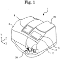
- Fig. 1 is an exterior view of the processing control data acquiring apparatus 1.
- the processing control data acquiring apparatus 1 includes a base 2, a housing 3, a window 4, the monitor 5, a lens processing mechanism portion 10 (refer to Fig. 2 ), the eyeglasses frame shape measuring unit 20, and the blocker unit 30.
- the lens processing mechanism portion 10, the eyeglasses frame shape measuring unit 20, and the blocker unit 30 are integrally attached to the base 2.
- the window 4 is capable of being open and closed, and is used for putting a lens LE in and out of the lens processing mechanism portion 10.
- the monitor 5 is mounted in the processing control data acquiring apparatus 1.
- the monitor 5 may be a monitor connected to the processing control data acquiring apparatus 1.
- a monitor of a personal computer may be used.
- a combination of a plurality of monitors may be used as the monitor 5.
- the monitor 5 is a display having a touch panel function. That is, the monitor 5 serves as an operation portion (the switch portion 6).
- the monitor 5 may not be a touch panel type monitor, and the monitor 5 and the operation portion may be provided separately from each other. In this case, at least one of a mouse, a joystick, a keyboard, and a mobile terminal may be used as the operation portion.
- a signal corresponding to an operation instruction input from the monitor 5 is output to the control portion 80 which will be described later.
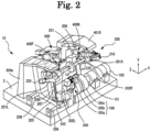
- Fig. 2 is a schematic view of the lens processing mechanism portion 10.
- the lens processing mechanism portion 10 is disposed inside the housing 3.
- the lens processing mechanism portion 10 includes a grindstone group 100, a carriage portion 200, a chamfering unit 300, the lens surface shape measuring unit 400, and a drilling and grooving unit 500.
- the grindstone group 100 includes a roughing grindstone 100a for plastic, a finishing grindstone 100b for beveling and plano-processing, and a polish-finishing grindstone 100c.
- the grindstone group 100 is attached to a grindstone rotary shaft 101.
- the grindstone rotary shaft 101 is rotated by a motor 102.
- a peripheral edge of the lens LE held in an interposed manner by a lens chuck shaft 202 (which will be described later) is processed by allowing the peripheral edge of the lens LE to come into press contact with the grindstone group 100 rotating via the driving of the motor 102.
- the carriage portion 200 includes a carriage 201, the lens chuck shaft 202, a movement support 203, and motors (motors 210 and 220).
- the carriage 201 holds the lens chuck shaft (lens rotary shaft) 202.
- the carriage 201 includes a right arm 201R and a left arm 201L.
- the lens chuck shaft 202 holds the lens LE.
- the lens chuck shaft 202 includes a right chuck shaft 202R and a left chuck shaft 202L.
- the left chuck shaft 202L is rotatably and coaxially held by the left arm 201L of the carriage 201.
- the right chuck shaft 202R is rotatably and coaxially held by the right arm 201R of the carriage 201.
- the motor 220 is attached to the left arm 201L. If the motor 220 is driven, a rotation transmission mechanism such as gears (not illustrated) rotates.
- the right chuck shaft 202R and the left chuck shaft 202L rotate synchronously with each other via the rotation transmission mechanism.
- the motor 210 is attached to the right arm 201R. If the motor 210 is driven, the right chuck shaft 202R moves to the left chuck shaft 202L. Therefore, the lens LE is held by the right chuck shaft 202R and the left chuck shaft 202L.
- the carriage 201 is mounted on the movement support 203.
- the movement support 203 moves the carriage 201 along the lens chuck shaft 202 and shafts (shafts 208 and 209) that is parallel with the grindstone rotary shaft 101.
- a ball screw (not illustrated) extending in parallel with the shaft 208 is attached to a rear portion of the movement support 203.
- the ball screw is attached to a rotary shaft of a motor 230. If the motor 230 is driven, the carriage 201 linearly moves together with the movement support 203 in an X-axis direction (that is, axial direction of the lens chuck shaft 202).
- An encoder (not illustrated) is provided on the rotary shaft of the motor 230, and detects a movement of the carriage 201 in the X-axis direction.
- Shafts 205 and 206 extending in a Y-axis direction are fixed to the movement support 203.
- a motor 240 is fixed to the movement support 203, and a driving force of the motor 240 is transmitted to a ball screw 207 extending in the Y-axis direction.
- the carriage 201 moves in the Y-axis direction due to the rotation of the ball screw 207.
- An encoder (not illustrated) is provided on a rotary shaft of the motor 240, and detects a movement of the carriage 201 in the Y-axis direction.
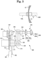
- Fig. 3 is a schematic view of the chamfering unit 300.
- the chamfering unit 300 is provided forward of the carriage 201.
- the chamfering unit 300 includes a support block 301, a fixation plate 302, a holding member 311, motors (pulse motor 305 and motor 321), gears (a gear 307, an idler gear 315, and a large gear 313), an arm rotating member 310, a grindstone rotary shaft 330, and a grindstone portion 340.
- the support block 301 is fixed to the base 2, and the fixation plate 302 is fixed to the support block 301.
- the holding member 311 and the pulse motor 305 are fixed to the fixation plate 302.
- the holding member 311 rotatably holds the arm rotating member 310.
- the gear 307 is attached to a rotary shaft of the pulse motor 305.
- the gear 307 meshes with the idler gear 315, and the idler gear 315 meshes with the large gear 313.
- the large gear 313 is fixed to the arm rotating member 310, and an arm 320 is fixed to the arm rotating member 310. If the pulse motor 305 is driven, the rotation of the gear 307 is transmitted to the large gear 313 via the idler gear 315, and the arm 320 fixed to the arm rotating member 310 rotates. Therefore, the grindstone portion 340 moves between a processing position and a retreat position.
- the motor 321 for rotating the grindstones is fixed to the large gear 313, and rotates together with the large gear 313.
- a rotary shaft of the motor 321 is connected to a shaft 323.
- the shaft 323 is rotatably held inside the arm rotating member 310.
- a pulley 324 is attached to an end of the shaft 323.
- the holding member 331 is fixed to the arm 320.
- the holding member 331 rotatably holds the grindstone rotary shaft 330.
- a pulley 332 is attached to an end of the grindstone rotary shaft 330.
- the pulley 332 and the pulley 324 are connected together via a belt 335. If the motor 321 is driven, the rotation of the shaft 323 is transmitted to the grindstone rotary shaft 330 via the pulley 332, the pulley 324, and the belt 335, and the grindstone rotary shaft 330 rotates.
- the grindstone portion 340 is provided on the grindstone rotary shaft 330.
- the grindstone portion 340 includes a chamfering grindstone 350, and a polishing and chamfering grindstone 360.
- the chamfering grindstone 350 has a lens front surface chamfering grindstone 350a, and a lens rear surface chamfering grindstone 350b.
- the polishing and chamfering grindstone 360 has a lens front surface polishing and chamfering grindstone 360a, and a lens rear surface polishing and chamfering grindstone 360b.
- the processing position of the grindstone portion 340 is a position where the grindstone rotary shaft 330 is disposed on a plane on which a rotary shaft of the lens chuck shaft 202 and a rotary shaft of the grindstone rotary shaft 101 are positioned between the lens chuck shaft 202 and the grindstone rotary shaft 101. Therefore, similar to when the peripheral edge of the lens is processed by the grindstone group 100, it is possible to move the lens LE in the X-axis direction via the motor 230 and in the Y-axis direction via the motor 240. It is possible to change a shaft-to-shaft distance between the lens chuck shaft 202 and the grindstone rotary shaft 330, and chamfer the peripheral edge of the lens.
- the chamfering grindstone 350 is used as a processing tool.
- the polishing and chamfering grindstone 360 is used as a processing tool for polishing.
- grindstones are used as processing tools for faceting, and an end mill may be used as a processing tool for faceting.
- Fig. 4 is a schematic view of the lens surface shape measuring unit 400.
- the lens surface shape measuring unit 400 has a measurement portion 400F that measures an edge position of the front surface of the lens LE, and a measurement portion 400R that measures an edge position of the rear surface of the lens LE.
- the measurement portion 400F is illustrated. Because the measurement portion 400R is symmetrical with the measurement portion 400F in the rightward and leftward direction, "F" at the end of a reference sign assigned to each configuration element of the measurement portion 400F is capable of being replaced by "R".
- the lens surface shape measuring unit 400 is provided upward of the carriage 201.
- the lens surface shape measuring unit 400 includes a support block 400a, an attachment support 401F, a tracing stylus arm 404F, a hand 405F, a tracing stylus 406F, a slide base 410F, a motor 416F, and gears (a gear 415F and an idle gear 414F).
- the support block 400a is fixed to the base 2, and the attachment support 401F is fixed to the support block 400a.
- a rail 402F is fixed to the attachment support 401F, and a slider 403F is slidably attached onto the rail 402F.
- the slide base 410F is fixed to the slider 403F, and the tracing stylus arm 404F is fixed to the slide base 410F.
- the hand 405F having an L shape is fixed to a tip end of the tracing stylus arm 404F, and the tracing stylus 406F is fixed to a tip end of the hand 405F.
- the tracing stylus 406F comes into contact with the front surface of the lens LE.
- the motor 416F and an encoder 413F are fixed to the support block 400a.
- a rotary shaft of the motor 416F meshes with the gear 415F, and the gear 415F meshes with the idle gear 414F.
- the idle gear 414F meshes with a pinion 412F of the encoder 413F.
- a rack 411F is fixed to a lower end of the slide base 410F, and the rack 411F meshes with the pinion 412F. If the motor 416F is driven, the rotation of the motor 416F is transmitted to the rack 411F via the gear 415F, the idle gear 414F, and the pinion 412F. Therefore, the slide base 410F moves in the X-axis direction.
- the motor 416F presses the tracing stylus 406F against the lens LE with a constant force all the time.
- the encoder 413F detects the movement position of the slide base 410F in the X-axis direction.
- the edge position of the front surface of the lens LE is measured based on information such as the movement position of the slide base 410F in the X-axis direction, the rotation angle of the lens chuck shaft 202, and the movement position of the lens chuck shaft 202 in the Y-axis direction.
- the drilling and grooving unit 500 is used to perform at least one of drilling and grooving of the lens LE.
- the drilling and grooving unit 500 includes an end mill used as a processing tool for drilling the lens LE, and a grooving cutter used as a processing tool for grooving the lens LE. It is recommended that JP-A-2003-145328 is referenced for a detailed configuration of the drilling and grooving unit.
- the eyeglasses frame shape measuring unit 20 is used to trace the shape of the frame. It is possible to acquire an inner shape of the rim of the frame via the eyeglasses frame shape measuring unit 20. That is, it is possible to acquire the target lens shape of the eyeglasses via the eyeglasses frame shape measuring unit 20. It is recommended that JP-A-2014-52222 is referenced for the details of the eyeglasses frame shape measuring unit 20.
- Fig. 5 is a schematic view of the blocker unit 30.
- the blocker unit 30 includes a lens support mechanism 40, a cup attachment mechanism 50, and a lens measurement mechanism 60 (refer to Fig. 6 ).
- the lens is placed on the lens support mechanism 40 with the front surface of the lens facing upward.
- the cup attachment mechanism 50 is used to attach a cup CU to the front surface of the lens LE. That is, the cup attachment mechanism 50 is used to fix (center) the cup CU to the front surface of the lens LE.
- the lens support mechanism 40 includes a round tubular base 41, a protective cover 42, and a support pin 43.
- the protective cover 42 is installed on the round tubular base 41.
- An index plate 67 (which will be described later) and the like are disposed inside the round tubular base 41.
- Three support pins 43 are disposed on the protective cover 42 such that the support pins 43 are equidistant and equiangular from each other around a reference axis (optical axis) L1 for attaching the cup.
- the support pins 43 hold the lens LE by coming into contact with the rear surface (back surface) of the lens LE.
- the cup attachment mechanism 50 includes a movement support 51, a support arm 52, a movement arm 53, a shaft 54, and a cup mounting portion 55.
- Two support columns 56 are fixed to the round tubular base 41, and a block 57 is supported by upper ends of the support columns 56.
- the movement support 51 provided integrally with the movement arm 53 is attached to the support columns 56, and is capable of moving in the upward and downward direction.
- a spring (not illustrated) is disposed inside the movement support 51, and biases the movement support 51 upward all the time.
- the movement arm 53 is attached to the movement support 51, and extends forward of the movement support 51.
- the shaft 54 is attached to the movement arm 53.
- the axis of the shaft 54 is coaxial with an axis L2 extending in the rightward and leftward direction perpendicular to the optical axis L1.
- the movement arm 53 holds the support arm 52, and the support arm 52 supports the cup mounting portion 55.
- the support arm 52 is capable of rotating around the shaft 54 (that is, the axis L2) between a direction in which the cup mounting portion 55 faces the front side (operator) and a downward direction.
- a level 58 is fixed to the support arm 52, and is used for the operator to rotate the support arm 52.
- a coil spring (not illustrated) is provided on the shaft 54, and applies a biasing force such that the direction of the cup mounting portion 55 is changed from the downward direction to a forward direction.
- the cup mounting portion 55 faces the forward direction all the time.
- the cup CU is mounted on the cup mounting portion 55, and is a jig used for the lens chuck shaft 202 to hold the lens LE in an interposed manner.
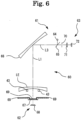
- Fig. 6 is a schematic configuration diagram of the lens measurement mechanism 60.
- the lens measurement mechanism 60 serves as both a measurement optical system for acquiring optical characteristics of a lens and a measurement optical system for acquiring information (for example, an outer shape of the lens, a printing point on the lens, and a hidden mark formed on the lens) different from the optical characteristics of the lens.
- the measurement optical system for acquiring optical characteristics of a lens and the measurement optical system for acquiring lens information different from the optical characteristics of the lens may be separately provided.
- the lens measurement mechanism 60 includes an illumination optical system 61, a light-receiving optical system 62, and the imaging optical system 63.
- the illumination optical system 61 includes a light source 64, a half mirror 65, and a concave surface mirror 66.
- the light source 64 radiates the lens with beams of measurement light.
- the light source 64 may be a light emitting diode (LED).
- the beams of measurement light emitted from the light source 64 is reflected by the half mirror 65 disposed on an optical axis L3, and coincides with the optical axis L3.
- the concave surface mirror 66 reflects beams of measurement light such that the axis of the beams of measurement light aligned with the optical axis L1 becomes aligned with the optical axis L3.
- the concave surface mirror 66 reshapes beams of measurement light into parallel beams of light (substantially parallel beams of light).having a diameter greater than that of the lens LE disposed on the
- the light-receiving optical system 62 includes the index plate 67, an imaging element 68, and the like.
- the index plate 67 is used to detect the optical center of the lens LE.
- a predetermined pattern of many openings (holes through which beams of light passes) are formed in the index plate 67.
- a region excluded from the predetermined pattern of region is formed by bonding a retroreflective member 69 to the excluded region.
- the imaging element 68 captures an image of beams of measurement light which is reflected from the light source 64 and passes through the lens LE and the index plate 67.
- the imaging element 68 may be a charge coupled device (CCD), a complementary metal oxide semiconductor (CMOS), or the like.
- the light-receiving optical system 62 may be configured such that the lens is disposed between the index plate 67 and the imaging element 68.
- the imaging optical system 63 includes the concave surface mirror 66, an aperture 70, an imaging lens 71, and an imaging element 72.
- the image magnification ratio of the imaging optical system 63 is a magnification ratio where an image of the entirety of the lens LE is captured by the imaging element 72.
- the concave surface mirror 66 is used in both the imaging optical system 63 and the illumination optical system 61.
- the aperture 70 is disposed at the focal position (substantially focal position) of the concave surface mirror 66.
- the position of the aperture 70 is conjugate (substantially conjugate) with that of the light source 64.
- the imaging element 72 captures an image of beams of reflected light which is reflected by the retroreflective member 69 among beams of light radiated from the light source 64.
- the imaging element 72 may be a CCD, a CMOS, or the like.
- the focal position of the imaging element 72 is located in the vicinity of the surface of the lens LE by the imaging lens 71 and the concave surface mirror 66. Therefore, it is possible to capture images of a printing point on the surface of the lens and a hidden mark formed on the lens in a state where a focus is substantially taken.
- Fig. 7 is a block diagram illustrating a control system of the processing control data acquiring apparatus 1.
- the control portion 80 is electrically connected to the monitor 5, the switch portion 6, the light source 64, each encoder, each motor (the motors 102, 210, 110, 230, 240, 305, 321, and 416F), each imaging element (the imaging element 68 and the imaging element 72), and a non-volatile memory 85 (hereinafter, memory 85).
- the memory 85 may be a non-transitory storage medium that is capable of holding stored content even though a power supply is shut down. It is possible to use a hard disk drive, a flash ROM, and an attachable and detachable USB memory as the memory 85.
- the memory 85 may store the target lens shape (first shape information) of the eyeglasses, facet shape information (second shape information) of a demonstration lens DL, the curve information (third shape information) of the lens LE, the processing control data acquired by the control portion 80.
- the control portion 80 is realized by a CPU (processor), a RAM, and a ROM which are commonly used.
- the CPU controls the driving of each part of the processing control data acquiring apparatus 1.
- the RAM temporarily stores various information.
- the ROM stores various programs executed by the CPU.
- the control portion 80 may be configured to include a plurality of control portions (that is, a plurality of processors).
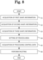
- a sequence of acquiring processing control data via the processing control data acquiring apparatus 1 will be described together with a control operation of the processing control data acquiring apparatus 1 with reference to the flowchart illustrated in Fig. 8 .
- a front surface of the demonstration lens DL is faceted, and faceting control data for forming at least one flat surface on the front surface of the lens LE is acquired.
- the control portion 80 acquires target lens shape information of an eyeglasses.
- the target lens shape information of the eyeglasses may be an inner shape of a rim of a frame, or an outer shape of the demonstration lens (or template).
- the embodiment exemplifies that the control portion 80 acquires the target lens shape information of the eyeglasses by capturing the entire image of the demonstration lens via the blocker unit 30 and measuring the outer shape of the demonstration lens.
- the control portion 80 may acquire target lens shape information by reading target lens shape information measured by a separate apparatus.
- the control portion 80 turns on the light source 64 in response to an input signal from the start button, and instructs the light source 64 to radiate the demonstration lens DL with beams of measurement light.
- the imaging element 72 receives beams of measurement light which is reflected by the retroreflective member 69 and illuminates from a rear surface of the demonstration lens DL. As a result, the entire image (demonstration lens image) of the demonstration lens DL is captured.
- the control portion 80 may capture a plurality of demonstration lens images while increasing or decreasing the light intensity of the light source 64.
- the control portion 80 acquires the outer shape of the demonstration lens DL, the position coordinates of the outer, and a boxing central position B by image processing the demonstration lens image.
- the outer shape of the demonstration lens DL is acquired by detecting differences between an image (reference image) of the demonstration lens DL not placed on the support pins 43 and the demonstration lens image.
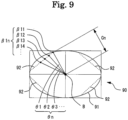
- Fig. 9 is a differential image 90 which is obtained by detecting differences between the reference image and the demonstration lens image.
- Both the reference image and the demonstration lens image are received light images which are images of light received by the imaging element 72. For this reason, the number of pixels of the reference image is the same as that of the demonstration lens image, and pixel positions in the reference image correspond to pixel positions in the demonstration lens image, respectively.
- the control portion 80 is capable of acquiring the differential image 90 by detecting a luminance value for each pixel position in the reference image and the demonstration lens image, and subtracting a luminance value for each pixel position in the demonstration lens image from a luminance value for each corresponding pixel position in the reference image.
- the control portion 80 detects an edge (edge illustrated by the solid line in Fig. 8 ) among edges appeared in the differential image 90, such that the area of a figure bounded by the edge becomes the maximum.
- the control portion 80 stores the edge in the memory 85 as an outer shape 91 of the demonstration lens.
- the boxing central position B is calculated as the point of intersection of straight lines that connect together the center points of facing sides of a rectangle surrounding the outer shape 91.
- the position coordinates of the outer form are expressed as two-dimensional coordinates having the boxing central position B as the origin.
- the position coordinates of points on the outer shape 91 may be obtained at every predetermined angle (for example, at every 0.36 degree) around the boxing central position B.
- the control portion 80 acquires facet shape information of the demonstration lens DL which is faceted.
- the facet shape information may contain the shape of a facet formed by faceting (in other words, the shape of a small surface formed by faceting), a process line defined by faceting (that is, edge line formed by faceting), a process width defined by faceting, and the like.
- the embodiment exemplifies that a process line defined by the faceting applied to the front surface of the demonstration lens DL is acquired.
- the control portion 80 detects a process line 92 (hereinafter, facet line 92) (determined by the faceting) from the demonstration lens image captured by the imaging element 72, as the facet shape information.
- facet line 92 is detected from the differential image 90 acquired based on the demonstration lens image.
- the control portion 80 detects an edge (edge illustrated by the dotted line in Fig. 8 ) in contact with the outer shape 91 of the demonstration lens DL among the edges appeared in the differential image 90.
- the control portion 80 stores the edge as the facet line 92 of the demonstration lens DL.
- the range of detecting the facet line 92 from the differential image 90 may be set in advance to improve the accuracy of detection of the facet line 92.
- a range of pixel area located 5 mm inward from the outer shape 91 of the demonstration lens DL in the differential image 90 may be set as the range of detecting the facet line 92.
- the control portion 80 acquires the position coordinates of points ⁇ 11, ⁇ 12, ⁇ 13, ⁇ 14, ..., ⁇ 1n on the facet line 92, which is detected, of the demonstration lens DL at every predetermined angle (that is, every radial angle ⁇ 1, ⁇ 2, ⁇ 3, ..., ⁇ n) around the boxing central position B serving as the origin.
- the control portion 80 obtains the length of each line segment Cn that connects the boxing central position B to each point ⁇ 1n on the facet line 92.
- the control portion 80 acquires curve information of the lens surface of the lens LE.
- the control portion 80 may acquire curve information of at least one of the front surface and the rear surface of the lens.
- the control portion 80 may acquire edge information of the lens in addition to the curve information. Because the embodiment exemplifies that the front surface of the demonstration lens DL is faceted, the control portion 80 acquires the curve information of the front surface of the lens LE.
- the control portion 80 may acquire both the curve information of the front surface of the lens LE and the curve information of the rear surface of the lens LE.
- the control portion 80 acquires the curve information by measuring the front surface of the lens LE via the lens surface shape measuring unit 400.
- the control portion 80 may acquire curve information by reading the curve information measured by a separate apparatus.
- the operator may measure curve information in advance via a curve scale, and the control portion 80 may acquire the curve information input by the operator.
- the operator attaches the cup CU (which is a processing jig) to the surface of the lens LE by using the blocker unit 30.
- the attachment position of the cup CU may be at least one of an optical central position A of the lens LE and the boxing central position B (that is, geometric central position B).
- the attachment position of the cup CU may be a position different from the optical central position A of the lens LE or the boxing central position B.
- the cup CU attached to the surface of the lens LE is mounted in a cup holder (not illustrated) of the lens chuck shaft 202 by the operator.
- the control portion 80 moves the right chuck shaft 202R by driving the carriage portion 200, and holds the lens LE in a predetermined state via the lens chuck shaft 202.
- the control portion 80 controls a relative movement of the lens chuck shaft 202 such that the tracing stylus 406F of the lens surface shape measuring unit 400 comes into contact with the front surface of the lens LE at two measurement positions.
- Two measurement positions on the front surface of the lens LE may be two measurement positions in at least one meridian direction having the axis (that is, the optical central position A of the lens LE) of the lens chuck shaft 202 as a center. More specifically, the measurement positions may be set to a position 2 mm inward and a position 3 mm inward from the target lens shape (in the embodiment, outer shape of the demonstration lens DL) of the eyeglasses in a direction in which a radial length from the lens chuck shaft 202 becomes the greatest.
- the control portion 80 acquires the curve information of the front surface of the lens LE based on the positions in the X direction for two measurement positions, the distances from the axis of the lens chuck shaft 202 to two measurement positions, and the position (already known as a measurement reference in the X direction) of the front surface of the lens LE in the X direction of the lens chuck shaft 202.
- the control portion 80 uses curve information of the lens LE to estimate the inclination angle of the curve of the front surface of the lens LE with respect to the optical central position A. That is, the control portion 80 estimates the curved shape of the front surface of the lens LE.
- the control portion 80 sets a process area of the faceting applied to the lens LE.
- the process area of the faceting may be set based on the outer shape 91 (that is, target lens shape of the eyeglasses) of the demonstration lens DL and the facet line 92 (that is, facet shape information) detected from the demonstration lens DL. If the curve information of the lens LE is acquired as in the embodiment, the control portion 80 may set the process area based on the outer shape 91 of the demonstration lens DL, the facet line 92, and the curve information of the lens LE, which will be described hereinafter.
- control portion 80 acquires the outer shape 91 of the demonstration lens DL, the facet line 92 of the demonstration lens DL, and the curve information of the lens LE, the control portion 80 sets a process area of the faceting, which is applied to the lens LE, for every radial angle of the lens LE.
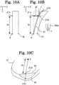
- the process area of the faceting is set by calculating a point ⁇ 2n (refer to Figs.
- Figs. 10A to 10C illustrate views describing the calculation of the point ⁇ 2n on the processing trajectory 93 afterward of the faceting.
- Fig. 10A is a view of a side surface of the demonstration lens DL as seen in the direction of a radial angle.
- Fig. 10B is a view of a side surface of the lens LE as seen in the direction of a radial angle.
- Fig. 10C is a view of the lens LE which is faceted.
- Each point ⁇ 1n on the facet line 92 and the length of the line segment Cn, which connects the boxing central position B to each point ⁇ 1n on the facet line 92, are obtained at every radial angle based on the outer shape 91 and the facet line 92 of the demonstration lens DL acquired in Step S1 and Step S2. Because the outer shape 91 and the facet line 92 of the demonstration lens DL are two-dimensional shapes, the position of each point thereon is expressed as a two-dimensional coordinate (Y-Z coordinate). On the other hand, because the lens LE, the processing of which is required, has a curved shape, each point ⁇ 1n on the facet line 92 of the demonstration lens DL is not necessarily positioned on the front surface of the lens LE.
- the control portion 80 obtains the position coordinate of the point ⁇ 2n on the lens LE, which corresponds to the point ⁇ 1n on the facet line 92.
- the control portion 80 moves the point ⁇ 1n parallel to the X direction, and calculates the position of the point ⁇ 2n in contact with the front surface of the lens LE by using the curved shape of the front surface of the lens LE.
- the control portion 80 obtains the length of a side g1 (which connects the optical central position A to the point ⁇ 2n) via linear approximation, and calculates the length (which is the distance by which the point ⁇ 1n is moved parallel to the X direction) of a side g2 by a trigonometric function of the side g1 and the line segment Cn. Therefore, the change amount of a coordinate in the X direction for the position coordinate of the point ⁇ 1n on the facet line 92 is obtained, and the three-dimensional coordinate (X-Y-Z coordinate) of the point ⁇ 2n on the lens LE is calculated
- the point ⁇ 2n on the processing trajectory 93 afterward of the faceting is obtained at every radial angle via such computational process.
- the point ⁇ 2n is expressed as a three-dimensional orthogonal coordinate.
- the operator is capable of manually adjusting the process area of the faceting, which is set by the control portion 80.
- the control portion 80 displays the process area on the monitor 5, which is based on the outer shape 91 of the demonstration lens DL, the facet line 92 of the demonstration lens DL, and the curve information of the lens LE.
- the control portion 80 sets a process area based on an operation signal that is output from the switch portion 6 to adjust the process area displayed on the monitor 5.
- Fig. 11 is an example of a display screen of the monitor 5.
- the monitor 5 displays a cross-sectional shape 95 of the lens LE, the outer shape 91, the facet line 92, a cursor 96, and an input column 97.
- the cross-sectional shape 95 of the lens LE may be displayed to have the same size as that of the outer shape 91 such that a correlation between the cross-sectional shape 95 and the outer shape 91 is easily understood.
- the cross-sectional shape 95 of the lens LE may be displayed based on the edge information (for example, edge positions of the front surface and the rear surface of the lens LE, and edge thicknesses of the lens LE) and the outer shape 91 of the lens LE.
- the operator designates the direction of observation of the edge surface of the lens LE by operating the cursor 96, and allows the monitor 5 to display the cross-sectional shape 95.
- the operator may set the facet line 92 by designating two points P1 and P2 on the outer shape 91, and connecting together the points P1 and P2.
- the operator may input a process width W, which is defined by the faceting, via the input column 97. Therefore, it is possible to more appropriately correct the process area of the faceting applied to the lens LE.
- the control portion 80 acquires faceting control data for forming at least one flat surface on a lens surface (in the embodiment, the front surface of the lens LE) of the lens LE.
- the faceting control data is acquired based on the process area of the faceting, which is set in Step S4.
- the control portion 80 computes the faceting control data for controlling the rotation of the lens chuck shaft 202 of the carriage portion 200 and the movement of the lens chuck shaft 202 based on the process area of the faceting, which is set using the outer shape 91 of the demonstration lens DL, the facet line 92 of the demonstration lens DL, and the curve information of the lens LE.
- the control portion 80 processes the peripheral edge and a lens surface of the lens LE.
- the control portion 80 moves the carriage 201, and processes the peripheral edge of the lens LE held in an interposed manner by the lens chuck shaft 202, based on the outer shape 91 of the demonstration lens DL.
- the control portion 80 flat-finishes the peripheral edge of the lens LE via the finishing grindstone 100b after roughing the peripheral edge of the lens LE via the roughing grindstone 100a.
- the control portion 80 disposes the grindstone rotary shaft 330 of the chamfering unit 300 at a processing position, and processes the lens surface of the lens LE based on the faceting control data.
- the control portion 80 facets the front surface of the lens LE by controlling the movement of the lens chuck shaft 202 in the X-axis direction and the Y-axis direction, and bringing the front surface of the lens LE into contact with the lens front surface chamfering grindstone 350a. Therefore, it is possible to obtain the lens LE which is appropriately faceted.
- the processing control data acquiring apparatus acquires target lens shape information of an eyeglasses lens, and facet shape information of a demonstration lens which is faceted, as facet shape information detected from the demonstration lens for the eyeglasses, and acquires faceting control data for forming at least one flat surface on a lens surface of the eyeglasses lens based on the target lens shape information and the facet shape information.
- An operator is capable of automatically setting the faceting, and appropriately faceting the eyeglasses lens by using the faceting control data.
- the processing control data acquiring apparatus acquires curve information of the lens surface of the eyeglasses lens, and acquires faceting control data based on the target lens shape information, the facet shape information, and the curve information. Because the curve information of the eyeglasses lens does not necessarily match curve information of the demonstration lens, it is possible to more accurately facet the eyeglasses lens by acquiring and using the faceting control data taking account of the curve information of the eyeglasses lens.
- the processing control data acquiring apparatus includes the imaging optical system that captures an image of a lens surface of the demonstration lens, and detects facet shape information from a lens image of the demonstration lens, which is captured by the imaging optical system. Therefore, the operator is capable of easily acquiring facet shape information from the eyeglasses lens which is faceted. It is also possible to further simplify an operation of acquiring the information by using the imaging optical system in the acquisition of both the target lens shape information of the eyeglasses and the facet shape information.
- the processing control data acquiring apparatus sets a process area to be faceted on the eyeglasses lens, and acquires faceting control data based on the set process area.
- the operator is capable of easily estimating the shape of the eyeglasses lens after the faceting of the eyeglasses lens by confirming the set process area.
- the operator is capable of determining whether the set process area is appropriate.
- the processing control data acquiring apparatus displays the process area of the faceting, which is applied to the eyeglasses lens, on the display portion, sets a process area based on an operation signal that is output from the operation portion to adjust the process area displayed on the display portion, and acquires faceting control data that is adjusted based on the setting. Therefore, the operator is capable of acquiring faceting control data by which the eyeglasses lens is to be more appropriately faceted.
- the embodiment exemplifies a configuration in which the outer shape of the demonstration lens DL is acquired as target lens shape information of eyeglasses.
- An inner shape of a frame may be acquired as the target lens shape information of the eyeglasses. If a rim of the frame has a protrusion portion that is to be fitted into a groove formed in the lens LE, an inner shape of the protrusion portion of the rim may be acquired as the inner shape of the frame. If the rim of the frame has a recessed portion into which a bevel formed in the lens LE is to be fitted, an inner shape of the recessed portion of the rim may be acquired as the inner shape of the frame.
- the inner shape of the frame may be acquired by a measurement portion having a contact type configuration in which the tracing stylus of the eyeglasses frame shape measuring unit 20 comes into contact with the frame.
- the inner shape of the frame may be acquired by a measurement portion having a non-contact type configuration in which the measurement portion has a light-radiating optical system that radiates beams of measurement light, and a light-receiving optical system that receives beams of reflected light from the reflection of the beams of measurement light.
- the embodiment exemplifies a configuration in which the outer shape 91 of the demonstration lens DL is acquired by the blocker unit 30 (that is, having a non-contact type configuration).
- the outer shape 91 of the demonstration lens DL may be acquired by the measurement portion having a contact type configuration in which the tracing stylus of the eyeglasses frame shape measuring unit 20 comes into contact with the frame.
- the tracing stylus may move along the peripheral edge of the demonstration lens DL while being in contact with the peripheral edge of the demonstration lens DL, and the outer shape of the demonstration lens DL may be acquired from movement positions.
- the embodiment exemplifies a configuration in which facet shape information is detected by image processing a demonstration lens image which is a captured image of the demonstration lens DL.
- the demonstration lens DL may be radiated with beams of measurement light in many directions, and the facet shape information may be detected based on the position of a light-receiving surface receiving beams of reflected light and the time of receiving the beams of reflected light.
- the embodiment exemplifies a configuration in which the monitor 5 displays a display screen for setting a process area, and the process area of faceting is set by changing the facet line 92 and the like on the display screen.
- the present invention is not limited to the configuration.
- a demonstration lens image captured by the blocker unit 30 may be displayed on the monitor 5, and the outer shape 91 or the facet line 92 of the demonstration lens DL acquired in Step S1 and Step S2 may be displayed on the demonstration lens image while being superimposed on the demonstration lens image. Therefore, it is possible to trace the facet line 92 reflected on the demonstration lens image, and set a process area of the faceting.
- the present invention is not limited to the configuration in which the facet line 92 of the demonstration lens DL is traced. However, the outer shape 91 of the demonstration lens DL may be traced. If the demonstration lens DL is drilled, the position of a hole may be traced.
- the embodiment exemplifies a configuration in which curve information of the lens LE is acquired.
- edge information of the lens LE in addition to the curve information of the lens LE may be contained.
- the edge information may be an edge thickness or an edge position.
- the control portion 80 may determine whether it is possible to perform faceting.
- the point ⁇ 2n on the processing trajectory 93 afterward of the faceting may not be positioned on the edge surface depending on the curved shape of the lens LE. If faceting control data is prepared and the lens LE is processed in this state, the edge surface is cut away by the faceting, and the target lens shape becomes small.
- the control portion 80 may determine that it is not possible to perform the faceting if the point ⁇ 2n is out of the edge surface, based on the edge information of the lens LE. When the control portion 80 obtains a result of such determination, the control portion 80 may automatically change two positions where the outer shape 91 and the facet line 92 of the demonstration lens DL are in contact with each other, and prepare faceting control data again.
- the embodiment exemplifies a configuration in which a process area of faceting is set based on target lens shape information of eyeglasses, the facet shape information of the demonstration lens DL, and the curve information of the lens LE, and faceting control data is acquired based on the process area.
- Faceting control data may be acquired directly from the target lens shape information of the eyeglasses, the facet shape information of the demonstration lens DL, and the curve information of the lens LE.
- the embodiment may have a configuration in which the curve information of the lens LE and curve information of the demonstration lens DL are acquired.
- a process area of faceting may be set while taking account of the curve information of the demonstration lens DL.
- faceting control data may be prepared while taking account of the curve information of the demonstration lens DL.
- the embodiment exemplifies a configuration in which the processing control data acquiring apparatus 1 includes the lens processing mechanism portion 10 for processing the peripheral edge and a lens surface of the lens LE, and the lens LE is faceted by the processing control data acquiring apparatus 1.
- the present invention is not limited to the configuration.
- the processing control data acquired by the processing control data acquiring apparatus 1 may be transmitted to a separate apparatus, and the lens may be faceted by the separate apparatus.
Landscapes
- Engineering & Computer Science (AREA)
- Mechanical Engineering (AREA)
- Chemical & Material Sciences (AREA)
- Ceramic Engineering (AREA)
- Inorganic Chemistry (AREA)
- Grinding And Polishing Of Tertiary Curved Surfaces And Surfaces With Complex Shapes (AREA)
- Eyeglasses (AREA)
Description
- The present invention relates to a processing control data acquiring apparatus, a processing control data acquiring method and a processing control data acquiring program that acquire processing control data for processing an eyeglasses lens.
- There is known an eyeglasses lens processing apparatus that processes an eyeglasses lens. The eyeglasses lens processing apparatus acquires processing control data for forming a bevel or groove in a peripheral edge of the eyeglasses lens or making a hole in the eyeglasses lens, and performs processing based on the acquired processing control data. For the design of the eyeglasses lens, the eyeglasses lens processing apparatus may form a flat surface on a lens surface of the eyeglasses lens via faceting (For example, see
JP-A-2002-126983 - From
EP 1 852 216 A1 , an eyeglass lens processing apparatus for processing an eyeglass lens is known, which includes: a facetting tool that facets an edge corner of the lens which has been finished; a lens chuck that holds the lens; input means for inputting a target lens shape; lens measuring means for obtaining front and rear edge paths of the lens, which has been finished, based on the input target lens shape; display means for displaying a front outline graphic and a side outline graphic as view from at least one direction based on the measured front and rear edge paths; and setting means for setting a facetting area of the lens. The display means displays the set facetting area in the front and side outline graphics. - The faceting is manually set, and it is difficult to estimate the shape of the lens after the lens is faceted, and to accurately perform the setting. For this reason, the quality of the lens after the lens is faceted may not be good. It takes time and labor to set the faceting.
- An object of the present disclosure is to provide a processing control data acquiring apparatus, a processing control data acquiring method and a processing control data acquiring program that acquire processing control data with which an operator is capable of easily faceting an eyeglasses lens.
-
-
Fig. 1 is an exterior view of a processing control data acquiring apparatus. -
Fig. 2 is a schematic view of a lens processing mechanism portion. -
Fig. 3 is a schematic view of a chamfering unit. -
Fig. 4 is a schematic view of a lens surface shape measuring unit. -
Fig. 5 is a schematic view of a blocker unit. -
Fig. 6 is a schematic configuration diagram of a lens measurement mechanism. -
Fig. 7 is a diagram illustrating a control system of the processing control data acquiring apparatus. -
Fig. 8 is a flowchart illustrating a control operation. -
Fig. 9 is a differential image which is obtained by detecting differences between a reference image and a demonstration lens image. -
Figs. 10A to 10C illustrate views describing the calculation of a point on a processing trajectory afterward of faceting. -
Fig. 11 is an example of a display screen of a monitor. - An overview of a processing control data acquiring apparatus according to an embodiment of the present invention will be described. Hereinafter, items categorized by < > are used independently or connectedly.
- The processing control data acquiring apparatus includes a first shape information acquiring portion (for example, a control portion 80). The first shape information acquiring portion acquires target lens shape information of eyeglasses. The target lens shape information of the eyeglasses may be information on an outer shape of a demonstration lens or template. The target lens shape information of the eyeglasses may be information on an inner shape of a rim of an eyeglasses frame (hereinafter, frame). If the rim of the frame has a protrusion portion that is to be fitted into a groove formed in the lens, the first shape information acquiring portion may acquire an inner shape of the protrusion portion of the rim as the inner shape of the frame. If the rim of the frame has a recessed portion into which a bevel formed in the lens is to be fitted, the first shape information acquiring portion may acquire an inner shape of the recessed portion of the rim as the inner shape of the frame.
- The first shape information acquiring portion may acquire target lens shape information of the eyeglasses which is measured by a separate apparatus different from the processing control data acquiring apparatus. The first shape information acquiring portion may acquire the target lens shape information of the eyeglasses by measurement performed by a measurement portion (for example, an eyeglasses frame
shape measuring unit 20 or a blocker unit 30). The measurement portion may be configured as being a contact type unit to come into contact with at least one of the frame, the demonstration lens, and the template. The measurement portion may be configured as being a non-contact type unit not to come into contact with none of the frame, the demonstration lens, and the template. - The measurement portion having the contact type configuration may have a tracing stylus and a tracing stylus shaft. The tracing stylus may come into contact with the recessed portion of the rim, and move along the recessed portion of the rim. The tracing stylus shaft may come into contact with at least one of the protrusion portion of the rim, a peripheral edge of the demonstration lens, and a peripheral edge of the template, and move therealong. The first shape information acquiring portion is capable of acquiring target lens shape information of the eyeglasses by detecting movement positions of the tracing stylus or the tracing stylus shaft.
- The measurement portion having the non-contact type configuration may have a light-radiating optical system that radiates beams of measurement light, and a light-receiving optical system that receives beams of reflected light from the reflection of the beams of measurement light. The light-radiating optical system may radiate beams of measurement light onto at least one of the rim of the frame, the peripheral edge of the demonstration lens, and the peripheral edge of the template. The light-receiving optical system may receive beams of reflected light from the reflection of the beams of measurement light by at least one of the rim of the frame, the peripheral edge of the demonstration lens, and the peripheral edge of the template. The first shape information acquiring portion is capable of acquiring the target lens shape information of the eyeglasses by analyzing the beams of reflected light.
- The processing control data acquiring apparatus includes a second shape information acquiring portion (for example, the control portion 80). The second shape information acquiring portion acquires the facet shape information of the demonstration lens which is faceted, as facet shape information detected from the demonstration lens for the eyeglasses. The demonstration lens for the eyeglasses may be at least one of a demonstration lens fitted into a frame and a demonstration lens fixed to a frame. The facet shape information may be information containing at least one of the shape of a facet formed by faceting (in other words, the shape of a small surface formed by faceting), a process line defined by faceting (that is, edge line formed by faceting), a process width defined by faceting, and the like. The facet shape information detected from the demonstration lens may be facet shape information detected from a lens image (demonstration lens image) which is a captured image of the demonstration lens.
- The second shape information acquiring portion may acquire facet shape information from the demonstration lens which is faceted, by measuring the facet shape information via the measurement portion (for example, the blocker unit 30) of the eyeglasses lens processing control data acquiring apparatus. In this case, the measurement portion may include an imaging optical system (for example, imaging optical system 63) that captures an image of a lens surface of the demonstration lens. The second shape information acquiring portion may acquire facet shape information by detecting the facet shape information from a demonstration lens image captured by the imaging optical system. Therefore, an operator is capable of easily acquiring the facet shape information from an eyeglasses lens which is faceted. It is also possible to further simplify an operation of acquiring the information by using the imaging optical system in the acquisition of both the target lens shape information of the eyeglasses and the facet shape information.
- The second shape information acquiring portion may acquire the facet shape information that is measured by a separate apparatus different from the eyeglasses lens processing control data acquiring apparatus. The second shape information acquiring portion may acquire facet shape information by receiving a demonstration lens image captured by the separate apparatus, and detecting the facet shape information from the demonstration lens image. In this case, the second shape information acquiring portion may acquire facet shape information by receiving the facet shape information detected from the demonstration lens image captured by the separate apparatus.
- The second shape information acquiring portion may be configured to detect edges and acquire facet shape information by detecting an increase or decrease of luminance at each pixel position in the demonstration lens image. The second shape information acquiring portion may be configured to detect edges and acquire facet shape information by differencing between a reference image, which is not an image of the demonstration lens, and the demonstration lens image. In the differencing, a luminance value detected for each pixel position in the demonstration lens image may be divided by a luminance value for each corresponding pixel position in the reference image. A luminance value detected for each pixel position in the demonstration lens image may be subtracted from a luminance value detected for each corresponding pixel position in the reference image. The value detected for each pixel position may be a chroma or color, and is not limited to a luminance value.
- The processing control data acquiring apparatus includes a third shape information acquiring portion (for example, the control portion 80). The third shape information acquiring portion acquires curve information of a lens surface of the eyeglasses lens. The third shape information acquiring portion may be configured to acquire at least the curve information of the lens surface of the eyeglasses lens. The third shape information acquiring portion may acquire edge information in addition to the curve information. The edge information may include the thickness of an edge surface, the position of the edge surface, and the like.
- The third shape information acquiring portion may acquire curve information that is measured by a separate apparatus different from the processing control data acquiring apparatus. In the case, the operator may input eyeglasses lens curve information measured in advance by operating an operation portion (for example, a switch portion 6). The third shape information acquiring portion may acquire curve information of the lens surface of the eyeglasses lens by measuring the curve information via the measurement portion (for example, lens surface shape measuring unit 400).
- The third shape information acquiring portion may acquire curve information of a faceted lens surface of the eyeglasses lens. That is, if a front surface of the eyeglasses lens is faceted, the third shape information acquiring portion acquires curve information of at least the front surface of the eyeglasses lens. If a rear surface of the eyeglasses lens is faceted, the third shape information acquiring portion acquires curve information of at least the rear surface of the eyeglasses lens. If only one surface of the front surface and the rear surface of the eyeglasses lens is faceted, the third shape information acquiring portion may acquire curve information of both of a faceted surface and a non-faceted surface. If the front surface and the rear surface of the eyeglasses lens are faceted, the third shape information acquiring portion acquires curve information of each of the front surface and the rear surface of the eyeglasses lens.
- The processing control data acquiring apparatus includes a processing control data acquiring portion (for example, the control portion 80). The processing control data acquiring portion acquires faceting control data for forming at least one flat surface on a lens surface of the eyeglasses lens based on the target lens shape information and the facet shape information. That is, the processing control data acquiring portion acquires faceting control data for forming at least one flat surface on at least one of the front surface and the rear surface of the eyeglasses lens based on the target lens shape and the facet shape information. The faceting control data may be faceting control data for forming a plurality of flat surfaces on the front surface of the eyeglasses lens. The faceting control data may be faceting control data for forming a plurality of flat surfaces on the rear surface of the eyeglasses lens. The faceting control data may be faceting control data for forming a plurality of flat surfaces on the front surface of the eyeglasses lens, and a plurality of flat surfaces on the rear surface of the eyeglasses lens. The faceting control data may be acquired by computation performed by a control portion (for example, the control portion 80) of the processing control data acquiring apparatus.
- The processing control data acquiring portion acquires faceting control data for forming at least one flat surface on a lens surface of the eyeglasses lens based on the target lens shape information acquired by the first shape information acquiring portion and the facet shape information acquired by the second shape information acquiring portion. Therefore, the operator is capable of appropriately faceting the eyeglasses lens by being capable of automatically acquiring the facet shape information, and by using the faceting control data.
- The processing control data acquiring portion may acquire faceting control data based on the target lens shape information, the facet shape information, and the curve information acquired by the third shape information acquiring portion. Because the curve information of the eyeglasses lens does not necessarily match curve information of the demonstration lens, it is possible to more accurately facet the eyeglasses lens by acquiring and using the faceting control data taking account of the curve information of the eyeglasses lens.
- The embodiment may be configured such that the first shape information acquiring portion acquires the target lens shape information of the eyeglasses, the second shape information acquiring portion acquires facet shape information of a faceted front surface of the demonstration lens, the third shape information acquiring portion acquires the curve information of the front surface of the eyeglasses lens, and the processing control data acquiring portion acquires faceting control data for forming at least one flat surface on the front surface of the eyeglasses lens.
- In the embodiment, the processing control data acquiring portion may directly acquire processing control data based on the target lens shape information and the facet shape information. The processing control data acquiring portion may directly acquire processing control data based on the target lens shape information, the facet shape information, and the curve information. In the embodiment, the processing control data acquiring portion may acquire a process area to be faceted on the eyeglasses lens, and acquire processing control data for the process area.
- The processing control data acquiring apparatus includes a setting portion (for example, the control portion 80). The setting portion sets a process area to be faceted on the eyeglasses lens. The setting portion may set at least one of a start point and an end point of a process line defined by faceting, a process width defined by faceting, and the like as the process area. The process area is a process area that is set based on the target lens shape information and the facet shape information. If the curve information is acquired, the process area may be a process area that is set based on the target lens shape information, the facet shape information, and the curve information. In this case, the processing control data acquiring portion may acquire faceting control data based on the set process area. Therefore, the operator is capable of confirming the set process area, and estimating the shape of the eyeglasses lens after the faceting of the eyeglasses lens. The operator is capable of determining whether the set process area is appropriate.
- The setting portion may be configured to set a process area based on an operation signal from an operation portion for adjusting a process area displayed on a display portion (for example, monitor 5). In this case, the processing control data acquiring portion may acquire faceting control data that is adjusted based on the setting performed by the setting portion. Therefore, the operator is capable of acquiring faceting control data by which the eyeglasses lens is to be more appropriately faceted.
- According to the invention, a processing control data acquiring apparatus is defined according to appended claim 7. In this case, the processing control data acquiring apparatus facets the eyeglasses lens by controlling the processing tool based on the faceting control data acquired by the processing control data acquiring portion.
- In the embodiment, the faceting control data acquired by the processing control data acquiring portion of the processing control data acquiring apparatus may be used by the eyeglasses lens processing apparatus having a processing tool for processing an eyeglasses lens. In this case, the eyeglasses lens processing apparatus facets the eyeglasses lens by controlling the processing tool based on the faceting control data acquired by the processing control data acquiring apparatus.
- The present invention is not limited to the apparatus described in the embodiment. For example, terminal control software (program) for executing functions of the following embodiment is supplied to a system or apparatus via networks or various storage mediums, and a control device (for example, CPU) of the system or apparatus is capable of reading and executing the program.
- A processing control data acquiring apparatus 1 will be described with reference to the drawings. In the embodiment, an X direction denotes a rightward and leftward direction (horizontal direction) of the processing control data acquiring apparatus 1, a Y direction denotes an upward and downward direction (vertical direction), and a Z direction denotes a forward and rearward direction.
-
Fig. 1 is an exterior view of the processing control data acquiring apparatus 1. The processing control data acquiring apparatus 1 includes abase 2, a housing 3, awindow 4, themonitor 5, a lens processing mechanism portion 10 (refer toFig. 2 ), the eyeglasses frameshape measuring unit 20, and theblocker unit 30. The lensprocessing mechanism portion 10, the eyeglasses frameshape measuring unit 20, and theblocker unit 30 are integrally attached to thebase 2. Thewindow 4 is capable of being open and closed, and is used for putting a lens LE in and out of the lensprocessing mechanism portion 10. - The
monitor 5 is mounted in the processing control data acquiring apparatus 1. Themonitor 5 may be a monitor connected to the processing control data acquiring apparatus 1. In this case, a monitor of a personal computer may be used. A combination of a plurality of monitors may be used as themonitor 5. Themonitor 5 is a display having a touch panel function. That is, themonitor 5 serves as an operation portion (the switch portion 6). Themonitor 5 may not be a touch panel type monitor, and themonitor 5 and the operation portion may be provided separately from each other. In this case, at least one of a mouse, a joystick, a keyboard, and a mobile terminal may be used as the operation portion. A signal corresponding to an operation instruction input from themonitor 5 is output to thecontrol portion 80 which will be described later. -
Fig. 2 is a schematic view of the lensprocessing mechanism portion 10. The lensprocessing mechanism portion 10 is disposed inside the housing 3. The lensprocessing mechanism portion 10 includes agrindstone group 100, acarriage portion 200, achamfering unit 300, the lens surface shape measuring unit 400, and a drilling andgrooving unit 500. - The
grindstone group 100 includes aroughing grindstone 100a for plastic, a finishinggrindstone 100b for beveling and plano-processing, and a polish-finishinggrindstone 100c. Thegrindstone group 100 is attached to a grindstonerotary shaft 101. The grindstonerotary shaft 101 is rotated by amotor 102. A peripheral edge of the lens LE held in an interposed manner by a lens chuck shaft 202 (which will be described later) is processed by allowing the peripheral edge of the lens LE to come into press contact with thegrindstone group 100 rotating via the driving of themotor 102. - The
carriage portion 200 includes acarriage 201, the lens chuck shaft 202, amovement support 203, and motors (motors 210 and 220). Thecarriage 201 holds the lens chuck shaft (lens rotary shaft) 202. Thecarriage 201 includes aright arm 201R and aleft arm 201L. The lens chuck shaft 202 holds the lens LE. The lens chuck shaft 202 includes aright chuck shaft 202R and aleft chuck shaft 202L. - The
left chuck shaft 202L is rotatably and coaxially held by theleft arm 201L of thecarriage 201. Theright chuck shaft 202R is rotatably and coaxially held by theright arm 201R of thecarriage 201. Themotor 220 is attached to theleft arm 201L. If themotor 220 is driven, a rotation transmission mechanism such as gears (not illustrated) rotates. Theright chuck shaft 202R and theleft chuck shaft 202L rotate synchronously with each other via the rotation transmission mechanism. Themotor 210 is attached to theright arm 201R. If themotor 210 is driven, theright chuck shaft 202R moves to theleft chuck shaft 202L. Therefore, the lens LE is held by theright chuck shaft 202R and theleft chuck shaft 202L. - The
carriage 201 is mounted on themovement support 203. Themovement support 203 moves thecarriage 201 along the lens chuck shaft 202 and shafts (shafts 208 and 209) that is parallel with the grindstonerotary shaft 101. A ball screw (not illustrated) extending in parallel with theshaft 208 is attached to a rear portion of themovement support 203. The ball screw is attached to a rotary shaft of amotor 230. If themotor 230 is driven, thecarriage 201 linearly moves together with themovement support 203 in an X-axis direction (that is, axial direction of the lens chuck shaft 202). An encoder (not illustrated) is provided on the rotary shaft of themotor 230, and detects a movement of thecarriage 201 in the X-axis direction.Shafts right chuck shafts rotary shaft 101 is changed) are fixed to themovement support 203. Amotor 240 is fixed to themovement support 203, and a driving force of themotor 240 is transmitted to aball screw 207 extending in the Y-axis direction. Thecarriage 201 moves in the Y-axis direction due to the rotation of theball screw 207. An encoder (not illustrated) is provided on a rotary shaft of themotor 240, and detects a movement of thecarriage 201 in the Y-axis direction. -
Fig. 3 is a schematic view of thechamfering unit 300. Thechamfering unit 300 is provided forward of thecarriage 201. Thechamfering unit 300 includes asupport block 301, afixation plate 302, a holdingmember 311, motors (pulse motor 305 and motor 321), gears (agear 307, anidler gear 315, and a large gear 313), anarm rotating member 310, a grindstonerotary shaft 330, and agrindstone portion 340. - The
support block 301 is fixed to thebase 2, and thefixation plate 302 is fixed to thesupport block 301. The holdingmember 311 and thepulse motor 305 are fixed to thefixation plate 302. The holdingmember 311 rotatably holds thearm rotating member 310. Thegear 307 is attached to a rotary shaft of thepulse motor 305. Thegear 307 meshes with theidler gear 315, and theidler gear 315 meshes with thelarge gear 313. Thelarge gear 313 is fixed to thearm rotating member 310, and anarm 320 is fixed to thearm rotating member 310. If thepulse motor 305 is driven, the rotation of thegear 307 is transmitted to thelarge gear 313 via theidler gear 315, and thearm 320 fixed to thearm rotating member 310 rotates. Therefore, thegrindstone portion 340 moves between a processing position and a retreat position. - The
motor 321 for rotating the grindstones is fixed to thelarge gear 313, and rotates together with thelarge gear 313. A rotary shaft of themotor 321 is connected to ashaft 323. Theshaft 323 is rotatably held inside thearm rotating member 310. Apulley 324 is attached to an end of theshaft 323. The holdingmember 331 is fixed to thearm 320. The holdingmember 331 rotatably holds the grindstonerotary shaft 330. Apulley 332 is attached to an end of the grindstonerotary shaft 330. Thepulley 332 and thepulley 324 are connected together via abelt 335. If themotor 321 is driven, the rotation of theshaft 323 is transmitted to the grindstonerotary shaft 330 via thepulley 332, thepulley 324, and thebelt 335, and the grindstonerotary shaft 330 rotates. - The
grindstone portion 340 is provided on the grindstonerotary shaft 330. Thegrindstone portion 340 includes achamfering grindstone 350, and a polishing andchamfering grindstone 360. Thechamfering grindstone 350 has a lens frontsurface chamfering grindstone 350a, and a lens rearsurface chamfering grindstone 350b. The polishing andchamfering grindstone 360 has a lens front surface polishing andchamfering grindstone 360a, and a lens rear surface polishing andchamfering grindstone 360b. The processing position of thegrindstone portion 340 is a position where the grindstonerotary shaft 330 is disposed on a plane on which a rotary shaft of the lens chuck shaft 202 and a rotary shaft of the grindstonerotary shaft 101 are positioned between the lens chuck shaft 202 and the grindstonerotary shaft 101. Therefore, similar to when the peripheral edge of the lens is processed by thegrindstone group 100, it is possible to move the lens LE in the X-axis direction via themotor 230 and in the Y-axis direction via themotor 240. It is possible to change a shaft-to-shaft distance between the lens chuck shaft 202 and the grindstonerotary shaft 330, and chamfer the peripheral edge of the lens. - If a lens surface (that is, at least one of the front surface or rear surface of the lens LE) of the lens LE is faceted to form at least one flat surface on the lens surface, the
chamfering grindstone 350 is used as a processing tool. The polishing andchamfering grindstone 360 is used as a processing tool for polishing. In the embodiment, grindstones are used as processing tools for faceting, and an end mill may be used as a processing tool for faceting. -
Fig. 4 is a schematic view of the lens surface shape measuring unit 400. The lens surface shape measuring unit 400 has ameasurement portion 400F that measures an edge position of the front surface of the lens LE, and ameasurement portion 400R that measures an edge position of the rear surface of the lens LE. InFig. 2 , themeasurement portion 400F is illustrated. Because themeasurement portion 400R is symmetrical with themeasurement portion 400F in the rightward and leftward direction, "F" at the end of a reference sign assigned to each configuration element of themeasurement portion 400F is capable of being replaced by "R". - The lens surface shape measuring unit 400 is provided upward of the
carriage 201. The lens surface shape measuring unit 400 includes a support block 400a, anattachment support 401F, atracing stylus arm 404F, ahand 405F, atracing stylus 406F, aslide base 410F, amotor 416F, and gears (agear 415F and anidle gear 414F). - The support block 400a is fixed to the
base 2, and theattachment support 401F is fixed to the support block 400a. Arail 402F is fixed to theattachment support 401F, and aslider 403F is slidably attached onto therail 402F. Theslide base 410F is fixed to theslider 403F, and thetracing stylus arm 404F is fixed to theslide base 410F. Thehand 405F having an L shape is fixed to a tip end of thetracing stylus arm 404F, and thetracing stylus 406F is fixed to a tip end of thehand 405F. Thetracing stylus 406F comes into contact with the front surface of the lens LE. - The
motor 416F and anencoder 413F are fixed to the support block 400a. A rotary shaft of themotor 416F meshes with thegear 415F, and thegear 415F meshes with theidle gear 414F. Theidle gear 414F meshes with apinion 412F of theencoder 413F. Arack 411F is fixed to a lower end of theslide base 410F, and therack 411F meshes with thepinion 412F. If themotor 416F is driven, the rotation of themotor 416F is transmitted to therack 411F via thegear 415F, theidle gear 414F, and thepinion 412F. Therefore, theslide base 410F moves in the X-axis direction. - During the measurement of the shape of the lens surface, the
motor 416F presses thetracing stylus 406F against the lens LE with a constant force all the time. Theencoder 413F detects the movement position of theslide base 410F in the X-axis direction. The edge position of the front surface of the lens LE is measured based on information such as the movement position of theslide base 410F in the X-axis direction, the rotation angle of the lens chuck shaft 202, and the movement position of the lens chuck shaft 202 in the Y-axis direction. - The drilling and
grooving unit 500 is used to perform at least one of drilling and grooving of the lens LE. The drilling andgrooving unit 500 includes an end mill used as a processing tool for drilling the lens LE, and a grooving cutter used as a processing tool for grooving the lens LE. It is recommended thatJP-A-2003-145328 - The eyeglasses frame
shape measuring unit 20 is used to trace the shape of the frame. It is possible to acquire an inner shape of the rim of the frame via the eyeglasses frameshape measuring unit 20. That is, it is possible to acquire the target lens shape of the eyeglasses via the eyeglasses frameshape measuring unit 20. It is recommended thatJP-A-2014-52222 shape measuring unit 20. -
Fig. 5 is a schematic view of theblocker unit 30. Theblocker unit 30 includes alens support mechanism 40, acup attachment mechanism 50, and a lens measurement mechanism 60 (refer toFig. 6 ). The lens is placed on thelens support mechanism 40 with the front surface of the lens facing upward. Thecup attachment mechanism 50 is used to attach a cup CU to the front surface of the lens LE. That is, thecup attachment mechanism 50 is used to fix (center) the cup CU to the front surface of the lens LE. - The
lens support mechanism 40 includes a roundtubular base 41, aprotective cover 42, and asupport pin 43. Theprotective cover 42 is installed on the roundtubular base 41. An index plate 67 (which will be described later) and the like are disposed inside the roundtubular base 41. Three support pins 43 are disposed on theprotective cover 42 such that the support pins 43 are equidistant and equiangular from each other around a reference axis (optical axis) L1 for attaching the cup. The support pins 43 hold the lens LE by coming into contact with the rear surface (back surface) of the lens LE. - The
cup attachment mechanism 50 includes amovement support 51, asupport arm 52, amovement arm 53, ashaft 54, and acup mounting portion 55. Twosupport columns 56 are fixed to the roundtubular base 41, and ablock 57 is supported by upper ends of thesupport columns 56. Themovement support 51 provided integrally with themovement arm 53 is attached to thesupport columns 56, and is capable of moving in the upward and downward direction. A spring (not illustrated) is disposed inside themovement support 51, and biases themovement support 51 upward all the time. Themovement arm 53 is attached to themovement support 51, and extends forward of themovement support 51. Theshaft 54 is attached to themovement arm 53. The axis of theshaft 54 is coaxial with an axis L2 extending in the rightward and leftward direction perpendicular to the optical axis L1. Themovement arm 53 holds thesupport arm 52, and thesupport arm 52 supports thecup mounting portion 55. Thesupport arm 52 is capable of rotating around the shaft 54 (that is, the axis L2) between a direction in which thecup mounting portion 55 faces the front side (operator) and a downward direction. Alevel 58 is fixed to thesupport arm 52, and is used for the operator to rotate thesupport arm 52. A coil spring (not illustrated) is provided on theshaft 54, and applies a biasing force such that the direction of thecup mounting portion 55 is changed from the downward direction to a forward direction. When the operator does not operate thelever 58, thecup mounting portion 55 faces the forward direction all the time. The cup CU is mounted on thecup mounting portion 55, and is a jig used for the lens chuck shaft 202 to hold the lens LE in an interposed manner. -
Fig. 6 is a schematic configuration diagram of thelens measurement mechanism 60. In the embodiment, thelens measurement mechanism 60 serves as both a measurement optical system for acquiring optical characteristics of a lens and a measurement optical system for acquiring information (for example, an outer shape of the lens, a printing point on the lens, and a hidden mark formed on the lens) different from the optical characteristics of the lens. The measurement optical system for acquiring optical characteristics of a lens and the measurement optical system for acquiring lens information different from the optical characteristics of the lens may be separately provided. - The
lens measurement mechanism 60 includes an illuminationoptical system 61, a light-receivingoptical system 62, and the imagingoptical system 63. The illuminationoptical system 61 includes alight source 64, ahalf mirror 65, and aconcave surface mirror 66. Thelight source 64 radiates the lens with beams of measurement light. Thelight source 64 may be a light emitting diode (LED). The beams of measurement light emitted from thelight source 64 is reflected by thehalf mirror 65 disposed on an optical axis L3, and coincides with the optical axis L3. Theconcave surface mirror 66 reflects beams of measurement light such that the axis of the beams of measurement light aligned with the optical axis L1 becomes aligned with the optical axis L3. Theconcave surface mirror 66 reshapes beams of measurement light into parallel beams of light (substantially parallel beams of light).having a diameter greater than that of the lens LE disposed on the optical axis L1. - The light-receiving
optical system 62 includes theindex plate 67, animaging element 68, and the like. Theindex plate 67 is used to detect the optical center of the lens LE. A predetermined pattern of many openings (holes through which beams of light passes) are formed in theindex plate 67. In the embodiment, a region excluded from the predetermined pattern of region is formed by bonding aretroreflective member 69 to the excluded region. Theimaging element 68 captures an image of beams of measurement light which is reflected from thelight source 64 and passes through the lens LE and theindex plate 67. Theimaging element 68 may be a charge coupled device (CCD), a complementary metal oxide semiconductor (CMOS), or the like. In the embodiment, the light-receivingoptical system 62 may be configured such that the lens is disposed between theindex plate 67 and theimaging element 68. - The imaging
optical system 63 includes theconcave surface mirror 66, anaperture 70, animaging lens 71, and animaging element 72. The image magnification ratio of the imagingoptical system 63 is a magnification ratio where an image of the entirety of the lens LE is captured by theimaging element 72. Theconcave surface mirror 66 is used in both the imagingoptical system 63 and the illuminationoptical system 61. Theaperture 70 is disposed at the focal position (substantially focal position) of theconcave surface mirror 66. The position of theaperture 70 is conjugate (substantially conjugate) with that of thelight source 64. Theimaging element 72 captures an image of beams of reflected light which is reflected by theretroreflective member 69 among beams of light radiated from thelight source 64. Theimaging element 72 may be a CCD, a CMOS, or the like. The focal position of theimaging element 72 is located in the vicinity of the surface of the lens LE by theimaging lens 71 and theconcave surface mirror 66. Therefore, it is possible to capture images of a printing point on the surface of the lens and a hidden mark formed on the lens in a state where a focus is substantially taken. -
Fig. 7 is a block diagram illustrating a control system of the processing control data acquiring apparatus 1. Thecontrol portion 80 is electrically connected to themonitor 5, theswitch portion 6, thelight source 64, each encoder, each motor (themotors imaging element 68 and the imaging element 72), and a non-volatile memory 85 (hereinafter, memory 85). Thememory 85 may be a non-transitory storage medium that is capable of holding stored content even though a power supply is shut down. It is possible to use a hard disk drive, a flash ROM, and an attachable and detachable USB memory as thememory 85. Thememory 85 may store the target lens shape (first shape information) of the eyeglasses, facet shape information (second shape information) of a demonstration lens DL, the curve information (third shape information) of the lens LE, the processing control data acquired by thecontrol portion 80. - The
control portion 80 is realized by a CPU (processor), a RAM, and a ROM which are commonly used. The CPU controls the driving of each part of the processing control data acquiring apparatus 1. The RAM temporarily stores various information. The ROM stores various programs executed by the CPU. Thecontrol portion 80 may be configured to include a plurality of control portions (that is, a plurality of processors). - Hereinafter, a sequence of acquiring processing control data via the processing control data acquiring apparatus 1 will be described together with a control operation of the processing control data acquiring apparatus 1 with reference to the flowchart illustrated in
Fig. 8 . In the embodiment, a front surface of the demonstration lens DL is faceted, and faceting control data for forming at least one flat surface on the front surface of the lens LE is acquired. - Firstly, the
control portion 80 acquires target lens shape information of an eyeglasses. The target lens shape information of the eyeglasses may be an inner shape of a rim of a frame, or an outer shape of the demonstration lens (or template). The embodiment exemplifies that thecontrol portion 80 acquires the target lens shape information of the eyeglasses by capturing the entire image of the demonstration lens via theblocker unit 30 and measuring the outer shape of the demonstration lens. Thecontrol portion 80 may acquire target lens shape information by reading target lens shape information measured by a separate apparatus. - An operator places the demonstration lens DL on the support pins 43, and selects a start button from the
switch portion 6 displayed on themonitor 5 so as to start the measurement of the outer shape of the demonstration lens DL. Thecontrol portion 80 turns on thelight source 64 in response to an input signal from the start button, and instructs thelight source 64 to radiate the demonstration lens DL with beams of measurement light. Theimaging element 72 receives beams of measurement light which is reflected by theretroreflective member 69 and illuminates from a rear surface of the demonstration lens DL. As a result, the entire image (demonstration lens image) of the demonstration lens DL is captured. In order to acquire a demonstration lens image from which an outer shape or facet line (which will be described later) is easily detected, thecontrol portion 80 may capture a plurality of demonstration lens images while increasing or decreasing the light intensity of thelight source 64. - The
control portion 80 acquires the outer shape of the demonstration lens DL, the position coordinates of the outer, and a boxing central position B by image processing the demonstration lens image. The outer shape of the demonstration lens DL is acquired by detecting differences between an image (reference image) of the demonstration lens DL not placed on the support pins 43 and the demonstration lens image.Fig. 9 is adifferential image 90 which is obtained by detecting differences between the reference image and the demonstration lens image. Both the reference image and the demonstration lens image are received light images which are images of light received by theimaging element 72. For this reason, the number of pixels of the reference image is the same as that of the demonstration lens image, and pixel positions in the reference image correspond to pixel positions in the demonstration lens image, respectively. That is, the reference image and the demonstration lens image are in a pixel-to-pixel relationship. Thecontrol portion 80 is capable of acquiring thedifferential image 90 by detecting a luminance value for each pixel position in the reference image and the demonstration lens image, and subtracting a luminance value for each pixel position in the demonstration lens image from a luminance value for each corresponding pixel position in the reference image. Thecontrol portion 80 detects an edge (edge illustrated by the solid line inFig. 8 ) among edges appeared in thedifferential image 90, such that the area of a figure bounded by the edge becomes the maximum. Thecontrol portion 80 stores the edge in thememory 85 as anouter shape 91 of the demonstration lens. - The boxing central position B is calculated as the point of intersection of straight lines that connect together the center points of facing sides of a rectangle surrounding the
outer shape 91. The position coordinates of the outer form are expressed as two-dimensional coordinates having the boxing central position B as the origin. The position coordinates of points on theouter shape 91 may be obtained at every predetermined angle (for example, at every 0.36 degree) around the boxing central position B. - Subsequently, the
control portion 80 acquires facet shape information of the demonstration lens DL which is faceted. The facet shape information may contain the shape of a facet formed by faceting (in other words, the shape of a small surface formed by faceting), a process line defined by faceting (that is, edge line formed by faceting), a process width defined by faceting, and the like. The embodiment exemplifies that a process line defined by the faceting applied to the front surface of the demonstration lens DL is acquired. - The
control portion 80 detects a process line 92 (hereinafter, facet line 92) (determined by the faceting) from the demonstration lens image captured by theimaging element 72, as the facet shape information. In other words, an edge formed on a lens surface of the demonstration lens DL is detected as the facet shape information by thecontrol portion 80. In the embodiment, thefacet line 92 is detected from thedifferential image 90 acquired based on the demonstration lens image. Thecontrol portion 80 detects an edge (edge illustrated by the dotted line inFig. 8 ) in contact with theouter shape 91 of the demonstration lens DL among the edges appeared in thedifferential image 90. Thecontrol portion 80 stores the edge as thefacet line 92 of the demonstration lens DL. The range of detecting thefacet line 92 from thedifferential image 90 may be set in advance to improve the accuracy of detection of thefacet line 92. In this case, a range of pixel area located 5 mm inward from theouter shape 91 of the demonstration lens DL in thedifferential image 90 may be set as the range of detecting thefacet line 92. - In the embodiment, the
control portion 80 acquires the position coordinates of points β11, β12, β13, β14, ..., β1n on thefacet line 92, which is detected, of the demonstration lens DL at every predetermined angle (that is, every radial angle θ1, θ2, θ3, ..., θn) around the boxing central position B serving as the origin. Thecontrol portion 80 obtains the length of each line segment Cn that connects the boxing central position B to each point β1n on thefacet line 92. - Subsequently, the
control portion 80 acquires curve information of the lens surface of the lens LE. Thecontrol portion 80 may acquire curve information of at least one of the front surface and the rear surface of the lens. Thecontrol portion 80 may acquire edge information of the lens in addition to the curve information. Because the embodiment exemplifies that the front surface of the demonstration lens DL is faceted, thecontrol portion 80 acquires the curve information of the front surface of the lens LE. Thecontrol portion 80 may acquire both the curve information of the front surface of the lens LE and the curve information of the rear surface of the lens LE. - The
control portion 80 acquires the curve information by measuring the front surface of the lens LE via the lens surface shape measuring unit 400. Thecontrol portion 80 may acquire curve information by reading the curve information measured by a separate apparatus. The operator may measure curve information in advance via a curve scale, and thecontrol portion 80 may acquire the curve information input by the operator. - The operator attaches the cup CU (which is a processing jig) to the surface of the lens LE by using the
blocker unit 30. The attachment position of the cup CU may be at least one of an optical central position A of the lens LE and the boxing central position B (that is, geometric central position B). The attachment position of the cup CU may be a position different from the optical central position A of the lens LE or the boxing central position B. Subsequently, the cup CU attached to the surface of the lens LE is mounted in a cup holder (not illustrated) of the lens chuck shaft 202 by the operator. Thecontrol portion 80 moves theright chuck shaft 202R by driving thecarriage portion 200, and holds the lens LE in a predetermined state via the lens chuck shaft 202. - The
control portion 80 controls a relative movement of the lens chuck shaft 202 such that thetracing stylus 406F of the lens surface shape measuring unit 400 comes into contact with the front surface of the lens LE at two measurement positions. Two measurement positions on the front surface of the lens LE may be two measurement positions in at least one meridian direction having the axis (that is, the optical central position A of the lens LE) of the lens chuck shaft 202 as a center. More specifically, the measurement positions may be set to aposition 2 mm inward and a position 3 mm inward from the target lens shape (in the embodiment, outer shape of the demonstration lens DL) of the eyeglasses in a direction in which a radial length from the lens chuck shaft 202 becomes the greatest. As a result, two positions on the front surface of the lens LE in the X direction are acquired. Thecontrol portion 80 acquires the curve information of the front surface of the lens LE based on the positions in the X direction for two measurement positions, the distances from the axis of the lens chuck shaft 202 to two measurement positions, and the position (already known as a measurement reference in the X direction) of the front surface of the lens LE in the X direction of the lens chuck shaft 202. - Using curve information of the lens LE, the
control portion 80 estimates the inclination angle of the curve of the front surface of the lens LE with respect to the optical central position A. That is, thecontrol portion 80 estimates the curved shape of the front surface of the lens LE. - Subsequently, the
control portion 80 sets a process area of the faceting applied to the lens LE. The process area of the faceting may be set based on the outer shape 91 (that is, target lens shape of the eyeglasses) of the demonstration lens DL and the facet line 92 (that is, facet shape information) detected from the demonstration lens DL. If the curve information of the lens LE is acquired as in the embodiment, thecontrol portion 80 may set the process area based on theouter shape 91 of the demonstration lens DL, thefacet line 92, and the curve information of the lens LE, which will be described hereinafter. - If the
control portion 80 acquires theouter shape 91 of the demonstration lens DL, thefacet line 92 of the demonstration lens DL, and the curve information of the lens LE, thecontrol portion 80 sets a process area of the faceting, which is applied to the lens LE, for every radial angle of the lens LE. In the embodiment, the process area of the faceting is set by calculating a point α2n (refer toFigs. 10A to 10C ) on aprocessing trajectory 93 afterward of the faceting at every radial angle θn based on the point β1n (in other words, point β1n on theprocessing trajectory 93 ahead of the faceting) on thefacet line 92 and the inclination angle of a grinding surface of the lens frontsurface chamfering grindstone 350a. -
Figs. 10A to 10C illustrate views describing the calculation of the point α2n on theprocessing trajectory 93 afterward of the faceting.Fig. 10A is a view of a side surface of the demonstration lens DL as seen in the direction of a radial angle.Fig. 10B is a view of a side surface of the lens LE as seen in the direction of a radial angle.Fig. 10C is a view of the lens LE which is faceted. Each point β1n on thefacet line 92 and the length of the line segment Cn, which connects the boxing central position B to each point β1n on thefacet line 92, are obtained at every radial angle based on theouter shape 91 and thefacet line 92 of the demonstration lens DL acquired in Step S1 and Step S2. Because theouter shape 91 and thefacet line 92 of the demonstration lens DL are two-dimensional shapes, the position of each point thereon is expressed as a two-dimensional coordinate (Y-Z coordinate). On the other hand, because the lens LE, the processing of which is required, has a curved shape, each point β1n on thefacet line 92 of the demonstration lens DL is not necessarily positioned on the front surface of the lens LE. - The
control portion 80 obtains the position coordinate of the point β2n on the lens LE, which corresponds to the point β1n on thefacet line 92. Thecontrol portion 80 moves the point β1n parallel to the X direction, and calculates the position of the point β2n in contact with the front surface of the lens LE by using the curved shape of the front surface of the lens LE. Thecontrol portion 80 obtains the length of a side g1 (which connects the optical central position A to the point β2n) via linear approximation, and calculates the length (which is the distance by which the point β1n is moved parallel to the X direction) of a side g2 by a trigonometric function of the side g1 and the line segment Cn. Therefore, the change amount of a coordinate in the X direction for the position coordinate of the point β1n on thefacet line 92 is obtained, and the three-dimensional coordinate (X-Y-Z coordinate) of the point β2n on the lens LE is calculated. - Subsequently, the
control portion 80 draws a straight line from the point β2n on the lens LE to an edge surface of the lens LE at an inclination angle γ of the grinding surface of the lens frontsurface chamfering grindstone 350a, and obtains the position coordinate (xn, yn, zn) (n=1, 2, 3, ..., N) of the point α2n, which is a position where the straight line comes into contact with the edge surface of the lens LE. The point α2n on theprocessing trajectory 93 afterward of the faceting is obtained at every radial angle via such computational process. In the embodiment, the point α2n is expressed as a three-dimensional orthogonal coordinate. The point α2n may be expressed as a coordinate (rn, zn, θn) (n= 1, 2, 3, ..., N) obtained by appropriately converting the position in the X and Y directions into a two-dimensional polar coordinate expressed by the radial angle θn and the radial length rn, and expressing the position in the Z direction as a Z coordinate. - The operator is capable of manually adjusting the process area of the faceting, which is set by the
control portion 80. In this case, thecontrol portion 80 displays the process area on themonitor 5, which is based on theouter shape 91 of the demonstration lens DL, thefacet line 92 of the demonstration lens DL, and the curve information of the lens LE. Thecontrol portion 80 sets a process area based on an operation signal that is output from theswitch portion 6 to adjust the process area displayed on themonitor 5.Fig. 11 is an example of a display screen of themonitor 5. Themonitor 5 displays across-sectional shape 95 of the lens LE, theouter shape 91, thefacet line 92, acursor 96, and aninput column 97. Thecross-sectional shape 95 of the lens LE may be displayed to have the same size as that of theouter shape 91 such that a correlation between thecross-sectional shape 95 and theouter shape 91 is easily understood. Thecross-sectional shape 95 of the lens LE may be displayed based on the edge information (for example, edge positions of the front surface and the rear surface of the lens LE, and edge thicknesses of the lens LE) and theouter shape 91 of the lens LE. - The operator designates the direction of observation of the edge surface of the lens LE by operating the
cursor 96, and allows themonitor 5 to display thecross-sectional shape 95. The operator may set thefacet line 92 by designating two points P1 and P2 on theouter shape 91, and connecting together the points P1 and P2. The operator may input a process width W, which is defined by the faceting, via theinput column 97. Therefore, it is possible to more appropriately correct the process area of the faceting applied to the lens LE. - If the process area of the faceting is set, the
control portion 80 acquires faceting control data for forming at least one flat surface on a lens surface (in the embodiment, the front surface of the lens LE) of the lens LE. In the embodiment, the faceting control data is acquired based on the process area of the faceting, which is set in Step S4. - The
control portion 80 computes the faceting control data for controlling the rotation of the lens chuck shaft 202 of thecarriage portion 200 and the movement of the lens chuck shaft 202 based on the process area of the faceting, which is set using theouter shape 91 of the demonstration lens DL, thefacet line 92 of the demonstration lens DL, and the curve information of the lens LE. Thecontrol portion 80 may acquire the faceting control data by converting the position coordinate (rn, zn, θn) (n= 1, 2, 3, ..., N) of each point β2n into the X-axis movement and the Y-axis movement of thecarriage 201 based on theprocessing trajectory 93 on the lens LE afterward of the faceting. - If the operator selects the start button from the
switch portion 6 displayed on themonitor 5 so as to start the processing of the lens LE, thecontrol portion 80 processes the peripheral edge and a lens surface of the lens LE. Thecontrol portion 80 moves thecarriage 201, and processes the peripheral edge of the lens LE held in an interposed manner by the lens chuck shaft 202, based on theouter shape 91 of the demonstration lens DL. Thecontrol portion 80 flat-finishes the peripheral edge of the lens LE via the finishinggrindstone 100b after roughing the peripheral edge of the lens LE via theroughing grindstone 100a. Subsequently, thecontrol portion 80 disposes the grindstonerotary shaft 330 of thechamfering unit 300 at a processing position, and processes the lens surface of the lens LE based on the faceting control data. Thecontrol portion 80 facets the front surface of the lens LE by controlling the movement of the lens chuck shaft 202 in the X-axis direction and the Y-axis direction, and bringing the front surface of the lens LE into contact with the lens frontsurface chamfering grindstone 350a. Therefore, it is possible to obtain the lens LE which is appropriately faceted. - As described above, in the embodiment, the processing control data acquiring apparatus acquires target lens shape information of an eyeglasses lens, and facet shape information of a demonstration lens which is faceted, as facet shape information detected from the demonstration lens for the eyeglasses, and acquires faceting control data for forming at least one flat surface on a lens surface of the eyeglasses lens based on the target lens shape information and the facet shape information. An operator is capable of automatically setting the faceting, and appropriately faceting the eyeglasses lens by using the faceting control data.
- In the embodiment, the processing control data acquiring apparatus acquires curve information of the lens surface of the eyeglasses lens, and acquires faceting control data based on the target lens shape information, the facet shape information, and the curve information. Because the curve information of the eyeglasses lens does not necessarily match curve information of the demonstration lens, it is possible to more accurately facet the eyeglasses lens by acquiring and using the faceting control data taking account of the curve information of the eyeglasses lens.
- In the embodiment, the processing control data acquiring apparatus includes the imaging optical system that captures an image of a lens surface of the demonstration lens, and detects facet shape information from a lens image of the demonstration lens, which is captured by the imaging optical system. Therefore, the operator is capable of easily acquiring facet shape information from the eyeglasses lens which is faceted. It is also possible to further simplify an operation of acquiring the information by using the imaging optical system in the acquisition of both the target lens shape information of the eyeglasses and the facet shape information.
- In the embodiment, the processing control data acquiring apparatus sets a process area to be faceted on the eyeglasses lens, and acquires faceting control data based on the set process area. The operator is capable of easily estimating the shape of the eyeglasses lens after the faceting of the eyeglasses lens by confirming the set process area. The operator is capable of determining whether the set process area is appropriate.
- In the embodiment, the processing control data acquiring apparatus displays the process area of the faceting, which is applied to the eyeglasses lens, on the display portion, sets a process area based on an operation signal that is output from the operation portion to adjust the process area displayed on the display portion, and acquires faceting control data that is adjusted based on the setting. Therefore, the operator is capable of acquiring faceting control data by which the eyeglasses lens is to be more appropriately faceted.
- The embodiment exemplifies a configuration in which the outer shape of the demonstration lens DL is acquired as target lens shape information of eyeglasses. However, the present invention is not limited to the configuration. An inner shape of a frame may be acquired as the target lens shape information of the eyeglasses. If a rim of the frame has a protrusion portion that is to be fitted into a groove formed in the lens LE, an inner shape of the protrusion portion of the rim may be acquired as the inner shape of the frame. If the rim of the frame has a recessed portion into which a bevel formed in the lens LE is to be fitted, an inner shape of the recessed portion of the rim may be acquired as the inner shape of the frame. The inner shape of the frame may be acquired by a measurement portion having a contact type configuration in which the tracing stylus of the eyeglasses frame
shape measuring unit 20 comes into contact with the frame. The inner shape of the frame may be acquired by a measurement portion having a non-contact type configuration in which the measurement portion has a light-radiating optical system that radiates beams of measurement light, and a light-receiving optical system that receives beams of reflected light from the reflection of the beams of measurement light. - The embodiment exemplifies a configuration in which the
outer shape 91 of the demonstration lens DL is acquired by the blocker unit 30 (that is, having a non-contact type configuration). However, the present invention is not limited to the configuration. Theouter shape 91 of the demonstration lens DL may be acquired by the measurement portion having a contact type configuration in which the tracing stylus of the eyeglasses frameshape measuring unit 20 comes into contact with the frame. In this case, the tracing stylus may move along the peripheral edge of the demonstration lens DL while being in contact with the peripheral edge of the demonstration lens DL, and the outer shape of the demonstration lens DL may be acquired from movement positions. - The embodiment exemplifies a configuration in which facet shape information is detected by image processing a demonstration lens image which is a captured image of the demonstration lens DL. The demonstration lens DL may be radiated with beams of measurement light in many directions, and the facet shape information may be detected based on the position of a light-receiving surface receiving beams of reflected light and the time of receiving the beams of reflected light.
- The embodiment exemplifies a configuration in which the
monitor 5 displays a display screen for setting a process area, and the process area of faceting is set by changing thefacet line 92 and the like on the display screen. However, the present invention is not limited to the configuration. A demonstration lens image captured by theblocker unit 30 may be displayed on themonitor 5, and theouter shape 91 or thefacet line 92 of the demonstration lens DL acquired in Step S1 and Step S2 may be displayed on the demonstration lens image while being superimposed on the demonstration lens image. Therefore, it is possible to trace thefacet line 92 reflected on the demonstration lens image, and set a process area of the faceting. The present invention is not limited to the configuration in which thefacet line 92 of the demonstration lens DL is traced. However, theouter shape 91 of the demonstration lens DL may be traced. If the demonstration lens DL is drilled, the position of a hole may be traced. - The embodiment exemplifies a configuration in which curve information of the lens LE is acquired. However, the present invention is not limited to the configuration. As described above, edge information of the lens LE in addition to the curve information of the lens LE may be contained. The edge information may be an edge thickness or an edge position. In this case, based on the edge information, the
control portion 80 may determine whether it is possible to perform faceting. The point α2n on theprocessing trajectory 93 afterward of the faceting may not be positioned on the edge surface depending on the curved shape of the lens LE. If faceting control data is prepared and the lens LE is processed in this state, the edge surface is cut away by the faceting, and the target lens shape becomes small. Thecontrol portion 80 may determine that it is not possible to perform the faceting if the point α2n is out of the edge surface, based on the edge information of the lens LE. When thecontrol portion 80 obtains a result of such determination, thecontrol portion 80 may automatically change two positions where theouter shape 91 and thefacet line 92 of the demonstration lens DL are in contact with each other, and prepare faceting control data again. - The embodiment exemplifies a configuration in which a process area of faceting is set based on target lens shape information of eyeglasses, the facet shape information of the demonstration lens DL, and the curve information of the lens LE, and faceting control data is acquired based on the process area. However, the present invention is not limited to the configuration. Faceting control data may be acquired directly from the target lens shape information of the eyeglasses, the facet shape information of the demonstration lens DL, and the curve information of the lens LE.
- The embodiment may have a configuration in which the curve information of the lens LE and curve information of the demonstration lens DL are acquired. In this case, a process area of faceting may be set while taking account of the curve information of the demonstration lens DL. In this case, faceting control data may be prepared while taking account of the curve information of the demonstration lens DL.
- The embodiment exemplifies a configuration in which the processing control data acquiring apparatus 1 includes the lens
processing mechanism portion 10 for processing the peripheral edge and a lens surface of the lens LE, and the lens LE is faceted by the processing control data acquiring apparatus 1. However, the present invention is not limited to the configuration. The processing control data acquired by the processing control data acquiring apparatus 1 may be transmitted to a separate apparatus, and the lens may be faceted by the separate apparatus. -
- 1 processing control data acquiring apparatus
- 10 lens processing mechanism portion
- 20 eyeglasses frame shape measuring unit
- 30 blocker unit
- 40 lens support mechanism
- 50 cup attachment mechanism
- 60 lens measurement mechanism
- 80 control portion
- 85 memory
- 100 grindstone group
- 200 carriage portion
- 300 chamfering unit
- 400 lens surface shape measuring unit
Claims (9)
- A processing control data acquiring apparatus (1) that acquires processing control data for processing an eyeglasses lens (LE), comprising:a first shape information acquiring portion (80) configured to acquire target lens shape information (91) of eyeglasses, characterized bya second shape information acquiring portion (80) configured to acquire facet shape information (92) of a demonstration lens (DL) which is faceted, the facet shape information (92) being detected from the demonstration lens (DL) for the eyeglasses (LE); anda processing control data acquiring portion (80) configured to acquire faceting control data for forming at least one flat surface on a lens surface of the eyeglasses lens (LE) based on the target lens shape information (91) and the facet shape information (92).
- The processing control data acquiring apparatus (1) according to claim 1, further comprising:a third shape information acquiring portion (80) configured to acquire curve information of the lens surface of the eyeglasses lens (LE),wherein the processing control data acquiring portion (80) is configured to acquire the faceting control data based on the target lens shape information (91), the facet shape information (92), and the curve information.
- The processing control data acquiring apparatus (1) according to claim 2,wherein the second shape information acquiring portion (80) is configured to acquire facet shape information (92) of a front surface of the demonstration lens (DL), the front surface being faceted,the third shape information acquiring portion (80) is configured to acquire curve information of a front surface of the eyeglasses lens (LE), andthe processing control data acquiring portion (80) is configured to acquire faceting control data for forming at least one flat surface on the front surface of the eyeglasses lens (LE).
- The processing control data acquiring apparatus (1) according to any one of claims 1 to 3, further comprising:an imaging optical system (63) configured to capture an image of a lens surface of the demonstration lens (DL),wherein the second shape information acquiring portion (80) is configured to detect the facet shape information (92) from a lens image of the demonstration lens (DL), which is captured by the imaging optical system (63), to acquire the facet shape information (92).
- The processing control data acquiring apparatus (1) according to any one of claims 1 to 4, further comprising:a setting portion (80) configured to set a process area to be faceted on the eyeglasses lens (LE),wherein the processing control data acquiring portion (80) is configured to acquire the faceting control data based on the set process area.
- The processing control data acquiring apparatus (1) according to claim 5,wherein the setting portion (80) is configured to set sets the process area based on an operation signal output from an operation portion for adjusting the process area displayed on a display portion (5), andthe processing control data acquiring portion (80) is configured to acquire the faceting control data that is adjusted based on a setting performed by the setting portion (80).
- An eyeglasses lens processing apparatus including a processing control data acquiring apparatus (1) according to any one of claims 1 to 6 and a processing tool (350, 360) for processing an eyeglasses lens (LE),
wherein the processing tool (350, 360) is controlled based on the faceting control data acquired by the processing control data acquiring apparatus to facet the eyeglasses lens (LE). - A processing control data acquiring method carried out by a processor (80) of a processing control data acquiring apparatus (1), that acquires processing control data for processing an eyeglasses lens (LE), comprising:a step of acquiring target lens shape information (91) of eyeglasses, characterized by a step of acquiring facet shape information (92) of a demonstration lens (DL) which is faceted, the facet shape information (92) being detected from the demonstration lens (DL) for the eyeglasses; anda step of acquiring faceting control data for forming at least one flat surface on a lens surface of the eyeglasses lens (LE) based on the target lens shape information (91) and the facet shape information (92).
- A processing control data acquiring program comprising instructions which, when
the processing control data acquiring program is executed by a processor (80) of a processing control data acquiring apparatus (1) that acquires processing control data for processing an eyeglasses lens (LE), causes the processing control data acquiring apparatus to execute:a step of acquiring target lens shape information (91) of eyeglasses (LE), characterized bya step of acquiring facet shape information (92) of a demonstration lens (DL) which is faceted, the facet shape information (92) being detected from the demonstration lens (DL) for the eyeglasses; anda step of acquiring faceting control data for forming at least one flat surface on a lens surface of the eyeglasses lens (LE) based on the target lens shape information (91) and the facet shape information (92).
Applications Claiming Priority (1)
| Application Number | Priority Date | Filing Date | Title |
|---|---|---|---|
| JP2018104224A JP7052567B2 (en) | 2018-05-31 | 2018-05-31 | Eyeglass lens processing control data acquisition device |
Publications (2)
| Publication Number | Publication Date |
|---|---|
| EP3575033A1 EP3575033A1 (en) | 2019-12-04 |
| EP3575033B1 true EP3575033B1 (en) | 2023-07-05 |
Family
ID=66668769
Family Applications (1)
| Application Number | Title | Priority Date | Filing Date |
|---|---|---|---|
| EP19176890.2A Active EP3575033B1 (en) | 2018-05-31 | 2019-05-28 | Processing control data acquiring apparatus, processing control data acquiring method and processing control data acquiring program |
Country Status (2)
| Country | Link |
|---|---|
| EP (1) | EP3575033B1 (en) |
| JP (1) | JP7052567B2 (en) |
Families Citing this family (1)
| Publication number | Priority date | Publication date | Assignee | Title |
|---|---|---|---|---|
| KR102544092B1 (en) * | 2022-01-10 | 2023-06-16 | 주식회사 아이니어 | Remote controllable lens edger and bigdata management server |
Citations (2)
| Publication number | Priority date | Publication date | Assignee | Title |
|---|---|---|---|---|
| EP0855248B1 (en) * | 1997-01-23 | 2003-10-22 | Wernicke & Co. GmbH | Method for NC shaping of spectacle lenses |
| EP2052814B1 (en) * | 2002-04-08 | 2013-09-11 | Hoya Corporation | Method for deciding a bevel curve, method for deciding a locus of a bevel, method for processing a lens and apparatus for processing a lens |
Family Cites Families (7)
| Publication number | Priority date | Publication date | Assignee | Title |
|---|---|---|---|---|
| DE4200637A1 (en) * | 1992-01-13 | 1993-07-15 | Wernicke & Co Gmbh | DEVICE FOR FACETTING EYE GLASSES |
| JP3990104B2 (en) | 2000-10-17 | 2007-10-10 | 株式会社ニデック | Lens grinding machine |
| JP3916445B2 (en) | 2001-11-08 | 2007-05-16 | 株式会社ニデック | Eyeglass lens processing equipment |
| JP5028025B2 (en) | 2006-05-02 | 2012-09-19 | 株式会社ニデック | Eyeglass lens peripheral processing equipment |
| JP6172430B2 (en) | 2012-09-05 | 2017-08-02 | 株式会社ニデック | Eyeglass frame shape measuring device |
| JP6127530B2 (en) | 2013-01-17 | 2017-05-17 | 株式会社ニデック | Eyeglass lens processing apparatus and processing control data creation program |
| JP6388416B2 (en) | 2017-05-04 | 2018-09-12 | 波田野 義行 | Eyeglass lens processing equipment |
-
2018
- 2018-05-31 JP JP2018104224A patent/JP7052567B2/en active Active
-
2019
- 2019-05-28 EP EP19176890.2A patent/EP3575033B1/en active Active
Patent Citations (2)
| Publication number | Priority date | Publication date | Assignee | Title |
|---|---|---|---|---|
| EP0855248B1 (en) * | 1997-01-23 | 2003-10-22 | Wernicke & Co. GmbH | Method for NC shaping of spectacle lenses |
| EP2052814B1 (en) * | 2002-04-08 | 2013-09-11 | Hoya Corporation | Method for deciding a bevel curve, method for deciding a locus of a bevel, method for processing a lens and apparatus for processing a lens |
Also Published As
| Publication number | Publication date |
|---|---|
| JP7052567B2 (en) | 2022-04-12 |
| JP2019209380A (en) | 2019-12-12 |
| EP3575033A1 (en) | 2019-12-04 |
Similar Documents
| Publication | Publication Date | Title |
|---|---|---|
| EP3663708B1 (en) | Eyeglass frame shape measurement device and lens processing device | |
| EP2335873B1 (en) | Eyeglass frame shape measurement apparatus | |
| EP1938923B1 (en) | Method of grinding eyeglass lens, and eyeglass lens grinding apparatus | |
| JP2007181889A (en) | Glass lens working system | |
| CN103586740A (en) | Minuteness and precision machining tool working shape online detection device and method | |
| EP3575033B1 (en) | Processing control data acquiring apparatus, processing control data acquiring method and processing control data acquiring program | |
| JP3215193B2 (en) | Method and apparatus for measuring blade shape of rotary tool | |
| US20120236139A1 (en) | Destructive web thickness measuring system of microdrills and method thereof | |
| JP7243043B2 (en) | Target shape measuring device | |
| EP3798566B1 (en) | Eyeglass frame shape measurement device and lens processing device | |
| JP7196849B2 (en) | Spectacle frame shape measuring device and spectacle frame shape measuring program | |
| JP7087366B2 (en) | Axis setting device, spectacle lens processing system, and spectacle lens processing method | |
| JP7172029B2 (en) | Alignment device | |
| EP3546121B1 (en) | Information acquiring apparatus, information acquiring method and information acquiring program | |
| US11022430B2 (en) | Eyeglass frame shape measurement device and storage medium | |
| JP7243706B2 (en) | Lens shape acquisition device | |
| CN110293471A (en) | The processing method of a kind of curve surface work pieces and for the equipment in this method | |
| JP6836154B2 (en) | Eyeglass lens peripheral processing information setting device, eyeglass lens peripheral processing device, and eyeglass lens peripheral processing information setting program | |
| JP7143652B2 (en) | Eyeglass measurement system and eyeglass measurement program |
Legal Events
| Date | Code | Title | Description |
|---|---|---|---|
| PUAI | Public reference made under article 153(3) epc to a published international application that has entered the european phase |
Free format text: ORIGINAL CODE: 0009012 |
|
| STAA | Information on the status of an ep patent application or granted ep patent |
Free format text: STATUS: THE APPLICATION HAS BEEN PUBLISHED |
|
| AK | Designated contracting states |
Kind code of ref document: A1 Designated state(s): AL AT BE BG CH CY CZ DE DK EE ES FI FR GB GR HR HU IE IS IT LI LT LU LV MC MK MT NL NO PL PT RO RS SE SI SK SM TR |
|
| AX | Request for extension of the european patent |
Extension state: BA ME |
|
| STAA | Information on the status of an ep patent application or granted ep patent |
Free format text: STATUS: REQUEST FOR EXAMINATION WAS MADE |
|
| 17P | Request for examination filed |
Effective date: 20200603 |
|
| RBV | Designated contracting states (corrected) |
Designated state(s): AL AT BE BG CH CY CZ DE DK EE ES FI FR GB GR HR HU IE IS IT LI LT LU LV MC MK MT NL NO PL PT RO RS SE SI SK SM TR |
|
| RIC1 | Information provided on ipc code assigned before grant |
Ipc: B24B 49/12 20060101ALI20221212BHEP Ipc: B24B 51/00 20060101ALI20221212BHEP Ipc: B24B 9/14 20060101AFI20221212BHEP |
|
| GRAP | Despatch of communication of intention to grant a patent |
Free format text: ORIGINAL CODE: EPIDOSNIGR1 |
|
| STAA | Information on the status of an ep patent application or granted ep patent |
Free format text: STATUS: GRANT OF PATENT IS INTENDED |
|
| INTG | Intention to grant announced |
Effective date: 20230307 |
|
| RIN1 | Information on inventor provided before grant (corrected) |
Inventor name: SHIMIZU, YUUKI |
|
| GRAS | Grant fee paid |
Free format text: ORIGINAL CODE: EPIDOSNIGR3 |
|
| GRAA | (expected) grant |
Free format text: ORIGINAL CODE: 0009210 |
|
| STAA | Information on the status of an ep patent application or granted ep patent |
Free format text: STATUS: THE PATENT HAS BEEN GRANTED |
|
| AK | Designated contracting states |
Kind code of ref document: B1 Designated state(s): AL AT BE BG CH CY CZ DE DK EE ES FI FR GB GR HR HU IE IS IT LI LT LU LV MC MK MT NL NO PL PT RO RS SE SI SK SM TR |
|
| REG | Reference to a national code |
Ref country code: CH Ref legal event code: EP |
|
| REG | Reference to a national code |
Ref country code: AT Ref legal event code: REF Ref document number: 1584387 Country of ref document: AT Kind code of ref document: T Effective date: 20230715 |
|
| REG | Reference to a national code |
Ref country code: DE Ref legal event code: R096 Ref document number: 602019032004 Country of ref document: DE |
|
| REG | Reference to a national code |
Ref country code: IE Ref legal event code: FG4D |
|
| P01 | Opt-out of the competence of the unified patent court (upc) registered |
Effective date: 20230630 |
|
| REG | Reference to a national code |
Ref country code: LT Ref legal event code: MG9D |
|
| REG | Reference to a national code |
Ref country code: NL Ref legal event code: MP Effective date: 20230705 |
|
| REG | Reference to a national code |
Ref country code: AT Ref legal event code: MK05 Ref document number: 1584387 Country of ref document: AT Kind code of ref document: T Effective date: 20230705 |
|
| PG25 | Lapsed in a contracting state [announced via postgrant information from national office to epo] |
Ref country code: NL Free format text: LAPSE BECAUSE OF FAILURE TO SUBMIT A TRANSLATION OF THE DESCRIPTION OR TO PAY THE FEE WITHIN THE PRESCRIBED TIME-LIMIT Effective date: 20230705 |
|
| PG25 | Lapsed in a contracting state [announced via postgrant information from national office to epo] |
Ref country code: GR Free format text: LAPSE BECAUSE OF FAILURE TO SUBMIT A TRANSLATION OF THE DESCRIPTION OR TO PAY THE FEE WITHIN THE PRESCRIBED TIME-LIMIT Effective date: 20231006 |
|
| PG25 | Lapsed in a contracting state [announced via postgrant information from national office to epo] |
Ref country code: ES Free format text: LAPSE BECAUSE OF FAILURE TO SUBMIT A TRANSLATION OF THE DESCRIPTION OR TO PAY THE FEE WITHIN THE PRESCRIBED TIME-LIMIT Effective date: 20230705 |
|
| PG25 | Lapsed in a contracting state [announced via postgrant information from national office to epo] |
Ref country code: IS Free format text: LAPSE BECAUSE OF FAILURE TO SUBMIT A TRANSLATION OF THE DESCRIPTION OR TO PAY THE FEE WITHIN THE PRESCRIBED TIME-LIMIT Effective date: 20231105 |
|
| PG25 | Lapsed in a contracting state [announced via postgrant information from national office to epo] |
Ref country code: SE Free format text: LAPSE BECAUSE OF FAILURE TO SUBMIT A TRANSLATION OF THE DESCRIPTION OR TO PAY THE FEE WITHIN THE PRESCRIBED TIME-LIMIT Effective date: 20230705 Ref country code: RS Free format text: LAPSE BECAUSE OF FAILURE TO SUBMIT A TRANSLATION OF THE DESCRIPTION OR TO PAY THE FEE WITHIN THE PRESCRIBED TIME-LIMIT Effective date: 20230705 Ref country code: PT Free format text: LAPSE BECAUSE OF FAILURE TO SUBMIT A TRANSLATION OF THE DESCRIPTION OR TO PAY THE FEE WITHIN THE PRESCRIBED TIME-LIMIT Effective date: 20231106 Ref country code: NO Free format text: LAPSE BECAUSE OF FAILURE TO SUBMIT A TRANSLATION OF THE DESCRIPTION OR TO PAY THE FEE WITHIN THE PRESCRIBED TIME-LIMIT Effective date: 20231005 Ref country code: LV Free format text: LAPSE BECAUSE OF FAILURE TO SUBMIT A TRANSLATION OF THE DESCRIPTION OR TO PAY THE FEE WITHIN THE PRESCRIBED TIME-LIMIT Effective date: 20230705 Ref country code: LT Free format text: LAPSE BECAUSE OF FAILURE TO SUBMIT A TRANSLATION OF THE DESCRIPTION OR TO PAY THE FEE WITHIN THE PRESCRIBED TIME-LIMIT Effective date: 20230705 Ref country code: IS Free format text: LAPSE BECAUSE OF FAILURE TO SUBMIT A TRANSLATION OF THE DESCRIPTION OR TO PAY THE FEE WITHIN THE PRESCRIBED TIME-LIMIT Effective date: 20231105 Ref country code: HR Free format text: LAPSE BECAUSE OF FAILURE TO SUBMIT A TRANSLATION OF THE DESCRIPTION OR TO PAY THE FEE WITHIN THE PRESCRIBED TIME-LIMIT Effective date: 20230705 Ref country code: GR Free format text: LAPSE BECAUSE OF FAILURE TO SUBMIT A TRANSLATION OF THE DESCRIPTION OR TO PAY THE FEE WITHIN THE PRESCRIBED TIME-LIMIT Effective date: 20231006 Ref country code: FI Free format text: LAPSE BECAUSE OF FAILURE TO SUBMIT A TRANSLATION OF THE DESCRIPTION OR TO PAY THE FEE WITHIN THE PRESCRIBED TIME-LIMIT Effective date: 20230705 Ref country code: ES Free format text: LAPSE BECAUSE OF FAILURE TO SUBMIT A TRANSLATION OF THE DESCRIPTION OR TO PAY THE FEE WITHIN THE PRESCRIBED TIME-LIMIT Effective date: 20230705 Ref country code: AT Free format text: LAPSE BECAUSE OF FAILURE TO SUBMIT A TRANSLATION OF THE DESCRIPTION OR TO PAY THE FEE WITHIN THE PRESCRIBED TIME-LIMIT Effective date: 20230705 |
|
| PG25 | Lapsed in a contracting state [announced via postgrant information from national office to epo] |
Ref country code: PL Free format text: LAPSE BECAUSE OF FAILURE TO SUBMIT A TRANSLATION OF THE DESCRIPTION OR TO PAY THE FEE WITHIN THE PRESCRIBED TIME-LIMIT Effective date: 20230705 |
|
| PG25 | Lapsed in a contracting state [announced via postgrant information from national office to epo] |
Ref country code: SM Free format text: LAPSE BECAUSE OF FAILURE TO SUBMIT A TRANSLATION OF THE DESCRIPTION OR TO PAY THE FEE WITHIN THE PRESCRIBED TIME-LIMIT Effective date: 20230705 Ref country code: RO Free format text: LAPSE BECAUSE OF FAILURE TO SUBMIT A TRANSLATION OF THE DESCRIPTION OR TO PAY THE FEE WITHIN THE PRESCRIBED TIME-LIMIT Effective date: 20230705 Ref country code: EE Free format text: LAPSE BECAUSE OF FAILURE TO SUBMIT A TRANSLATION OF THE DESCRIPTION OR TO PAY THE FEE WITHIN THE PRESCRIBED TIME-LIMIT Effective date: 20230705 Ref country code: DK Free format text: LAPSE BECAUSE OF FAILURE TO SUBMIT A TRANSLATION OF THE DESCRIPTION OR TO PAY THE FEE WITHIN THE PRESCRIBED TIME-LIMIT Effective date: 20230705 Ref country code: CZ Free format text: LAPSE BECAUSE OF FAILURE TO SUBMIT A TRANSLATION OF THE DESCRIPTION OR TO PAY THE FEE WITHIN THE PRESCRIBED TIME-LIMIT Effective date: 20230705 Ref country code: SK Free format text: LAPSE BECAUSE OF FAILURE TO SUBMIT A TRANSLATION OF THE DESCRIPTION OR TO PAY THE FEE WITHIN THE PRESCRIBED TIME-LIMIT Effective date: 20230705 |