EP3574939A1 - Wärmetauscher und künstliche lunge - Google Patents
Wärmetauscher und künstliche lunge Download PDFInfo
- Publication number
- EP3574939A1 EP3574939A1 EP18745313.9A EP18745313A EP3574939A1 EP 3574939 A1 EP3574939 A1 EP 3574939A1 EP 18745313 A EP18745313 A EP 18745313A EP 3574939 A1 EP3574939 A1 EP 3574939A1
- Authority
- EP
- European Patent Office
- Prior art keywords
- hollow fiber
- fiber membrane
- heat exchanger
- fiber membranes
- layer
- Prior art date
- Legal status (The legal status is an assumption and is not a legal conclusion. Google has not performed a legal analysis and makes no representation as to the accuracy of the status listed.)
- Pending
Links
- 210000004072 lung Anatomy 0.000 title 1
- 239000012510 hollow fiber Substances 0.000 claims abstract description 185
- 239000012528 membrane Substances 0.000 claims abstract description 185
- 229920002635 polyurethane Polymers 0.000 claims abstract description 9
- 239000004814 polyurethane Substances 0.000 claims abstract description 9
- 229920005672 polyolefin resin Polymers 0.000 claims abstract description 8
- 229920001903 high density polyethylene Polymers 0.000 claims abstract description 7
- 239000004700 high-density polyethylene Substances 0.000 claims abstract description 7
- MHAJPDPJQMAIIY-UHFFFAOYSA-N Hydrogen peroxide Chemical compound OO MHAJPDPJQMAIIY-UHFFFAOYSA-N 0.000 claims description 28
- -1 polyethylene Polymers 0.000 claims description 19
- 230000004888 barrier function Effects 0.000 claims description 18
- 239000000463 material Substances 0.000 claims description 11
- 239000004698 Polyethylene Substances 0.000 claims description 10
- 229920000573 polyethylene Polymers 0.000 claims description 10
- 229920006038 crystalline resin Polymers 0.000 claims description 4
- 239000008280 blood Substances 0.000 description 58
- 210000004369 blood Anatomy 0.000 description 58
- 239000007789 gas Substances 0.000 description 29
- 238000005192 partition Methods 0.000 description 21
- 230000002093 peripheral effect Effects 0.000 description 18
- 230000017531 blood circulation Effects 0.000 description 14
- 238000000034 method Methods 0.000 description 11
- XLYOFNOQVPJJNP-UHFFFAOYSA-N water Substances O XLYOFNOQVPJJNP-UHFFFAOYSA-N 0.000 description 11
- 229920005989 resin Polymers 0.000 description 9
- 239000011347 resin Substances 0.000 description 9
- 238000004804 winding Methods 0.000 description 9
- 230000000694 effects Effects 0.000 description 7
- 238000004519 manufacturing process Methods 0.000 description 7
- QVGXLLKOCUKJST-UHFFFAOYSA-N atomic oxygen Chemical compound [O] QVGXLLKOCUKJST-UHFFFAOYSA-N 0.000 description 6
- 239000001301 oxygen Substances 0.000 description 6
- 229910052760 oxygen Inorganic materials 0.000 description 6
- 239000004952 Polyamide Substances 0.000 description 5
- 229920002647 polyamide Polymers 0.000 description 5
- 239000004953 Aliphatic polyamide Substances 0.000 description 4
- 239000004743 Polypropylene Substances 0.000 description 4
- 229920003231 aliphatic polyamide Polymers 0.000 description 4
- 230000001788 irregular Effects 0.000 description 4
- 230000035699 permeability Effects 0.000 description 4
- 229920001155 polypropylene Polymers 0.000 description 4
- 230000008569 process Effects 0.000 description 4
- 238000010926 purge Methods 0.000 description 4
- 238000010521 absorption reaction Methods 0.000 description 3
- 229920001707 polybutylene terephthalate Polymers 0.000 description 3
- 229920000139 polyethylene terephthalate Polymers 0.000 description 3
- 239000005020 polyethylene terephthalate Substances 0.000 description 3
- 235000017166 Bambusa arundinacea Nutrition 0.000 description 2
- 235000017491 Bambusa tulda Nutrition 0.000 description 2
- 241001330002 Bambuseae Species 0.000 description 2
- 229920000219 Ethylene vinyl alcohol Polymers 0.000 description 2
- 229920000106 Liquid crystal polymer Polymers 0.000 description 2
- 239000004977 Liquid-crystal polymers (LCPs) Substances 0.000 description 2
- 229920000571 Nylon 11 Polymers 0.000 description 2
- 229920000299 Nylon 12 Polymers 0.000 description 2
- 229920002302 Nylon 6,6 Polymers 0.000 description 2
- 235000015334 Phyllostachys viridis Nutrition 0.000 description 2
- 239000004696 Poly ether ether ketone Substances 0.000 description 2
- 239000004734 Polyphenylene sulfide Substances 0.000 description 2
- 229920010524 Syndiotactic polystyrene Polymers 0.000 description 2
- 150000001336 alkenes Chemical class 0.000 description 2
- 239000011425 bamboo Substances 0.000 description 2
- 125000004432 carbon atom Chemical group C* 0.000 description 2
- 238000001816 cooling Methods 0.000 description 2
- 230000002708 enhancing effect Effects 0.000 description 2
- 238000010438 heat treatment Methods 0.000 description 2
- JRZJOMJEPLMPRA-UHFFFAOYSA-N olefin Natural products CCCCCCCC=C JRZJOMJEPLMPRA-UHFFFAOYSA-N 0.000 description 2
- 229920002530 polyetherether ketone Polymers 0.000 description 2
- 229920006324 polyoxymethylene Polymers 0.000 description 2
- 229920000069 polyphenylene sulfide Polymers 0.000 description 2
- 229920001343 polytetrafluoroethylene Polymers 0.000 description 2
- 239000004810 polytetrafluoroethylene Substances 0.000 description 2
- 238000011144 upstream manufacturing Methods 0.000 description 2
- YCKRFDGAMUMZLT-UHFFFAOYSA-N Fluorine atom Chemical compound [F] YCKRFDGAMUMZLT-UHFFFAOYSA-N 0.000 description 1
- 229920002292 Nylon 6 Polymers 0.000 description 1
- 229930182556 Polyacetal Natural products 0.000 description 1
- 239000004721 Polyphenylene oxide Substances 0.000 description 1
- XUIMIQQOPSSXEZ-UHFFFAOYSA-N Silicon Chemical compound [Si] XUIMIQQOPSSXEZ-UHFFFAOYSA-N 0.000 description 1
- NIXOWILDQLNWCW-UHFFFAOYSA-N acrylic acid group Chemical group C(C=C)(=O)O NIXOWILDQLNWCW-UHFFFAOYSA-N 0.000 description 1
- 239000000853 adhesive Substances 0.000 description 1
- 230000001070 adhesive effect Effects 0.000 description 1
- 125000003368 amide group Chemical group 0.000 description 1
- 239000000470 constituent Substances 0.000 description 1
- 230000007423 decrease Effects 0.000 description 1
- 229920000840 ethylene tetrafluoroethylene copolymer Polymers 0.000 description 1
- 239000004715 ethylene vinyl alcohol Substances 0.000 description 1
- 238000001125 extrusion Methods 0.000 description 1
- 229910052731 fluorine Inorganic materials 0.000 description 1
- 239000011737 fluorine Substances 0.000 description 1
- 229920001600 hydrophobic polymer Polymers 0.000 description 1
- 239000007788 liquid Substances 0.000 description 1
- 239000007791 liquid phase Substances 0.000 description 1
- FPYJFEHAWHCUMM-UHFFFAOYSA-N maleic anhydride Chemical compound O=C1OC(=O)C=C1 FPYJFEHAWHCUMM-UHFFFAOYSA-N 0.000 description 1
- 125000001570 methylene group Chemical group [H]C([H])([*:1])[*:2] 0.000 description 1
- 150000002825 nitriles Chemical class 0.000 description 1
- 239000012466 permeate Substances 0.000 description 1
- 238000005191 phase separation Methods 0.000 description 1
- 229920002492 poly(sulfone) Polymers 0.000 description 1
- 229920002239 polyacrylonitrile Polymers 0.000 description 1
- 229920000728 polyester Polymers 0.000 description 1
- 229920000570 polyether Polymers 0.000 description 1
- 239000002861 polymer material Substances 0.000 description 1
- 229920000306 polymethylpentene Polymers 0.000 description 1
- 239000011116 polymethylpentene Substances 0.000 description 1
- 229920000098 polyolefin Polymers 0.000 description 1
- 230000009467 reduction Effects 0.000 description 1
- 238000000926 separation method Methods 0.000 description 1
- 239000010703 silicon Substances 0.000 description 1
- 229910052710 silicon Inorganic materials 0.000 description 1
- KKEYFWRCBNTPAC-UHFFFAOYSA-L terephthalate(2-) Chemical compound [O-]C(=O)C1=CC=C(C([O-])=O)C=C1 KKEYFWRCBNTPAC-UHFFFAOYSA-L 0.000 description 1
- 238000003466 welding Methods 0.000 description 1
Images


Classifications
-
- A—HUMAN NECESSITIES
- A61—MEDICAL OR VETERINARY SCIENCE; HYGIENE
- A61M—DEVICES FOR INTRODUCING MEDIA INTO, OR ONTO, THE BODY; DEVICES FOR TRANSDUCING BODY MEDIA OR FOR TAKING MEDIA FROM THE BODY; DEVICES FOR PRODUCING OR ENDING SLEEP OR STUPOR
- A61M1/00—Suction or pumping devices for medical purposes; Devices for carrying-off, for treatment of, or for carrying-over, body-liquids; Drainage systems
- A61M1/14—Dialysis systems; Artificial kidneys; Blood oxygenators ; Reciprocating systems for treatment of body fluids, e.g. single needle systems for hemofiltration or pheresis
- A61M1/16—Dialysis systems; Artificial kidneys; Blood oxygenators ; Reciprocating systems for treatment of body fluids, e.g. single needle systems for hemofiltration or pheresis with membranes
- A61M1/1698—Blood oxygenators with or without heat-exchangers
-
- A—HUMAN NECESSITIES
- A61—MEDICAL OR VETERINARY SCIENCE; HYGIENE
- A61M—DEVICES FOR INTRODUCING MEDIA INTO, OR ONTO, THE BODY; DEVICES FOR TRANSDUCING BODY MEDIA OR FOR TAKING MEDIA FROM THE BODY; DEVICES FOR PRODUCING OR ENDING SLEEP OR STUPOR
- A61M1/00—Suction or pumping devices for medical purposes; Devices for carrying-off, for treatment of, or for carrying-over, body-liquids; Drainage systems
- A61M1/14—Dialysis systems; Artificial kidneys; Blood oxygenators ; Reciprocating systems for treatment of body fluids, e.g. single needle systems for hemofiltration or pheresis
- A61M1/16—Dialysis systems; Artificial kidneys; Blood oxygenators ; Reciprocating systems for treatment of body fluids, e.g. single needle systems for hemofiltration or pheresis with membranes
- A61M1/1621—Constructional aspects thereof
- A61M1/1629—Constructional aspects thereof with integral heat exchanger
-
- A—HUMAN NECESSITIES
- A61—MEDICAL OR VETERINARY SCIENCE; HYGIENE
- A61M—DEVICES FOR INTRODUCING MEDIA INTO, OR ONTO, THE BODY; DEVICES FOR TRANSDUCING BODY MEDIA OR FOR TAKING MEDIA FROM THE BODY; DEVICES FOR PRODUCING OR ENDING SLEEP OR STUPOR
- A61M1/00—Suction or pumping devices for medical purposes; Devices for carrying-off, for treatment of, or for carrying-over, body-liquids; Drainage systems
- A61M1/36—Other treatment of blood in a by-pass of the natural circulatory system, e.g. temperature adaptation, irradiation ; Extra-corporeal blood circuits
- A61M1/3621—Extra-corporeal blood circuits
- A61M1/3623—Means for actively controlling temperature of blood
-
- A—HUMAN NECESSITIES
- A61—MEDICAL OR VETERINARY SCIENCE; HYGIENE
- A61M—DEVICES FOR INTRODUCING MEDIA INTO, OR ONTO, THE BODY; DEVICES FOR TRANSDUCING BODY MEDIA OR FOR TAKING MEDIA FROM THE BODY; DEVICES FOR PRODUCING OR ENDING SLEEP OR STUPOR
- A61M1/00—Suction or pumping devices for medical purposes; Devices for carrying-off, for treatment of, or for carrying-over, body-liquids; Drainage systems
- A61M1/36—Other treatment of blood in a by-pass of the natural circulatory system, e.g. temperature adaptation, irradiation ; Extra-corporeal blood circuits
- A61M1/3621—Extra-corporeal blood circuits
- A61M1/3627—Degassing devices; Buffer reservoirs; Drip chambers; Blood filters
- A61M1/3633—Blood component filters, e.g. leukocyte filters
- A61M1/3635—Constructional details
-
- B—PERFORMING OPERATIONS; TRANSPORTING
- B01—PHYSICAL OR CHEMICAL PROCESSES OR APPARATUS IN GENERAL
- B01D—SEPARATION
- B01D63/00—Apparatus in general for separation processes using semi-permeable membranes
- B01D63/02—Hollow fibre modules
-
- B—PERFORMING OPERATIONS; TRANSPORTING
- B01—PHYSICAL OR CHEMICAL PROCESSES OR APPARATUS IN GENERAL
- B01D—SEPARATION
- B01D63/00—Apparatus in general for separation processes using semi-permeable membranes
- B01D63/02—Hollow fibre modules
- B01D63/021—Manufacturing thereof
- B01D63/022—Encapsulating hollow fibres
- B01D63/023—Encapsulating materials
-
- B—PERFORMING OPERATIONS; TRANSPORTING
- B01—PHYSICAL OR CHEMICAL PROCESSES OR APPARATUS IN GENERAL
- B01D—SEPARATION
- B01D71/00—Semi-permeable membranes for separation processes or apparatus characterised by the material; Manufacturing processes specially adapted therefor
- B01D71/06—Organic material
- B01D71/26—Polyalkenes
- B01D71/261—Polyethylene
-
- B—PERFORMING OPERATIONS; TRANSPORTING
- B01—PHYSICAL OR CHEMICAL PROCESSES OR APPARATUS IN GENERAL
- B01D—SEPARATION
- B01D71/00—Semi-permeable membranes for separation processes or apparatus characterised by the material; Manufacturing processes specially adapted therefor
- B01D71/06—Organic material
- B01D71/26—Polyalkenes
- B01D71/262—Polypropylene
-
- A—HUMAN NECESSITIES
- A61—MEDICAL OR VETERINARY SCIENCE; HYGIENE
- A61M—DEVICES FOR INTRODUCING MEDIA INTO, OR ONTO, THE BODY; DEVICES FOR TRANSDUCING BODY MEDIA OR FOR TAKING MEDIA FROM THE BODY; DEVICES FOR PRODUCING OR ENDING SLEEP OR STUPOR
- A61M2205/00—General characteristics of the apparatus
- A61M2205/02—General characteristics of the apparatus characterised by a particular materials
- A61M2205/0238—General characteristics of the apparatus characterised by a particular materials the material being a coating or protective layer
-
- A—HUMAN NECESSITIES
- A61—MEDICAL OR VETERINARY SCIENCE; HYGIENE
- A61M—DEVICES FOR INTRODUCING MEDIA INTO, OR ONTO, THE BODY; DEVICES FOR TRANSDUCING BODY MEDIA OR FOR TAKING MEDIA FROM THE BODY; DEVICES FOR PRODUCING OR ENDING SLEEP OR STUPOR
- A61M2205/00—General characteristics of the apparatus
- A61M2205/36—General characteristics of the apparatus related to heating or cooling
- A61M2205/366—General characteristics of the apparatus related to heating or cooling by liquid heat exchangers
Definitions
- the present invention relates to a heat exchanger and an oxygenator.
- a heat exchanger and an oxygenator having a hollow fiber membrane layer which is constituted of a large number of hollow fiber membranes and which has a cylindrical shape as a whole are known.
- a hollow fiber membrane sheet disclosed in PTL 1 can be applied.
- a large number of hollow fiber membranes are disposed substantially in parallel so as to be weft strings, and these are woven together with warp strings, thereby forming a bamboo blind-shaped sheet.
- Such a bamboo blind-shaped hollow fiber membrane sheet can be folded to form a hollow fiber membrane layer having a prismatic outer shape, or a hollow fiber membrane layer having a columnar shape.
- Such a hollow fiber membrane layer is housed in a housing, and both end portions thereof are fixed to the housing through the partition walls (fixing portions).
- An object of the present invention is to provide a heat exchanger and an oxygenator capable of reducing filling amount of a liquid (such as blood) to be subjected to heat exchange in the heat exchanger and capable of enhancing the adhesion between a hollow fiber membrane layer and a fixing portion.
- a liquid such as blood
- the present invention it is possible to enhance adhesion between the adhesion layer on the outermost layer of the hollow fiber membranes and the fixing portion. Accordingly, it is possible to prevent the hollow fiber membrane layer from being separated from the fixing portion, and to prevent the heat medium (water or hot water) passing through the inside of each of the hollow fiber membranes from flowing out to the outside of the hollow fiber membranes and being mixed into the patient's blood.
- the heat medium water or hot water
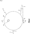
- Fig. 1 is a plan view of an oxygenator comprising a heat exchanger according to the present invention (first embodiment) .
- Fig. 2 is a view of the oxygenator shown in Fig. 1 when seen from a direction of arrow A.
- Fig. 3 is a cross-sectional view taken along line B-B in Fig. 2 .
- Fig. 4 is a view when seen from a direction of arrow C in Fig. 2 .
- Fig. 5 is a cross-sectional view taken along line D-D in Fig. 1 .
- Fig. 6 is a cross-sectional view taken along line E-E in Fig. 5 .
- FIG. 7 is a view (part (a) is a perspective view, and part (b) is a development view) showing a process of manufacturing a hollow fiber membrane layer provided in the oxygenator shown in Fig. 1 .
- Fig. 8 is a view (part (a) is a perspective view, and part (b) is a development view) showing the process of manufacturing the hollow fiber membrane layer provided in the oxygenator shown in Fig. 1 .
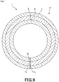
- Fig. 9 is a transverse view of a hollow fiber membrane provided in the hollow fiber membrane layer shown in Fig. 1 .
- Figs. 1 , 3 , 4 , and 7 to 9 the left side is referred to as “left” or a “left portion (one side)” and the right side is referred to as “right” or a “right portion (the other side)”.
- the inside of the oxygenator will be described as a "blood inflow side” or an “upstream side” and the outside will be described as a “blood outflow side” or a “downstream side”.
- an oxygenator 10 shown in Figs. 1 to 5 is in a substantially columnar shape.
- This oxygenator 10 is a heat exchanger-attached oxygenator comprising: a heat exchange portion 10B which is provided inside the oxygenator and performs heat exchange on blood; and an oxygenator portion 10A which is provided on an outer peripheral side of the heat exchange portion 10B and is used as a gas exchange portion performing gas exchange on blood.
- the oxygenator 10 is installed, for example, in an extracorporeal blood circulation circuit.
- the oxygenator 10 has a housing 2A in which the oxygenator portion 10A and the heat exchange portion (heat exchanger) 10B are housed.
- the housing 2A comprises : a cylindrical housing main body 21A; a dish-like first lid body 22A which seals a left end opening of the cylindrical housing main body 21A; and a dish-like second lid body 23A which seals a right end opening of the cylindrical housing main body 21A.
- the cylindrical housing main body 21A, the first lid body 22A, and the second lid body 23A are formed of a resin material.
- the first lid body 22A and the second lid body 23A are fixed to the cylindrical housing main body 21A through a method such as welding or adhesion using an adhesive.
- a tubular blood outlet port 28 is formed on the outer peripheral portion of the cylindrical housing main body 21A. This blood outlet port 28 protrudes toward a substantially tangential direction of the outer peripheral surface of the cylindrical housing main body 21A (refer to Fig. 5 ).
- a tubular purge port 205 is protrusively formed on the outer peripheral portion of the cylindrical housing main body 21A.
- the purge port 205 is formed on the outer peripheral portion of the cylindrical housing main body 21A such that a central axis of the purge port 205 intersects with a central axis of the cylindrical housing main body 21A.
- a tubular gas outlet port 27 is protrusively formed on the first lid body 22A.
- the gas outlet port 27 is formed on the outer peripheral portion of the first lid body 22A such that a central axis of the first lid body intersects with the center of the first lid body 22A (refer to Fig. 2 ).
- a blood inlet port 201 protrudes from an end surface of the first lid body 22A such that a central axis of the blood inlet port is eccentric to the center of the first lid body 22A.
- a tubular gas inlet port 26, a heat medium inlet port 202, and a heat medium outlet port 203 are protrusively formed on the second lid body 23A.
- the gas inlet port 26 is formed at an edge portion of the end surface of the second lid body 23A.
- the heat medium inlet port 202 and the heat medium outlet port 203 are formed at a substantially central portion of the end surface of the second lid body 23A.
- central lines of the heat medium inlet port 202 and the heat medium outlet port 203 are slightly inclined to a central line of the second lid body 23A.
- the entire shape of the housing 2A does not necessarily have a complete columnar shape, and may have, for example, a partially missing shape or a shape to which an irregular portion is added.
- the oxygenator portion 10A having a cylindrical shape along the inner peripheral surface of the housing 2A is housed inside the housing 2A.
- the oxygenator portion 10A comprises: a cylindrical hollow fiber membrane layer 3A; and a filter member 41A used as air bubble removing means 4A provided on the outer peripheral side of the hollow fiber membrane layer 3A.
- the hollow fiber membrane layer 3A and the filter member 41A are disposed in order of the hollow fiber membrane layer 3A and the filter member 41A from a blood inflow side.
- cylindrical heat exchange portion 10B is provided inside the oxygenator portion 10A and disposed along the inner peripheral surface of the oxygenator portion 10A.
- the heat exchange portion 10B has the cylindrical hollow fiber membrane layer 3B.
- each of the hollow fiber membrane layers 3A and 3B comprises a plurality of hollow fiber membranes 31, which are laminated in layers.
- the number of layers laminated is preferably, but not limited to, 3 to 40.
- each of the hollow fiber membranes 31 in the hollow fiber membrane layer 3A has a gas exchange function.
- each of the hollow fiber membranes 31 in the hollow fiber membrane layer 3B has a heat exchange function of performing heat exchange.
- both end portions of the hollow fiber membrane layers 3A and 3B are collectively fixed to the inner surface of the cylindrical housing main body 21A using partition walls 8 and 9.
- the partition walls 8 and 9 mainly contain polyurethane.
- the inner peripheral portion of the hollow fiber membrane layer 3B is engaged with an irregular portion 244 formed on the outer peripheral portion of a first cylindrical member 241.
- the hollow fiber membrane layer 3B is reliably fixed to the cylindrical housing main body 21A through fixation using the partition walls 8 and 9 and this engagement. Accordingly, it is possible to reliably prevent positional deviation of the hollow fiber membrane layer 3B from occurring during use of the oxygenator 10.
- the irregular portion 244 also functions as a flow path for circulating blood B throughout the hollow fiber membrane layer 3B.
- the maximum outer diameter ⁇ D1 max of the hollow fiber membrane layer 3A is preferably 20 mm to 200 mm, and more preferably 40 mm to 150 mm.
- the maximum outer diameter ⁇ D2 max of the hollow fiber membrane layer 3B is preferably 10 mm to 150 mm, and more preferably 20 mm to 100 mm.
- a length L of the hollow fiber membrane layers 3A and 3A along a central axis direction is preferably 30 mm to 250 mm, and more preferably 50 mm to 200 mm. With such conditions, the hollow fiber membrane layer 3A has an excellent gas exchange function and the hollow fiber membrane layer 3B has an excellent heat exchange function.
- a blood flow path 33 through which the blood B flows from the upper side to the lower side in Fig. 6 is formed on the outside of each of the hollow fiber membranes 31 between the partition wall 8 and the partition wall 9 in the housing 2A, that is, in a gap between the hollow fiber membranes 31.
- a blood inflow side space 24A communicating with the blood inlet port 201 is formed upstream of the blood flow path 33 as a blood inlet portion of the blood B flowing in from the blood inlet port 201 (refer to Figs. 3 and 5 ).
- the blood inflow side space 24A is a space defined by the first cylindrical member 241 forming a cylindrical shape and a plate piece 242 which is disposed inside the first cylindrical member 241 and is disposed so as to face a part of the inner peripheral portion of the first cylindrical member.
- the blood B flowing in the blood inflow side space 24A can flow down throughout blood flow paths 33 through a plurality of side holes 243 formed in the first cylindrical member 241.
- a second cylindrical member 245 concentrically disposed with the first cylindrical member 241 is disposed inside the first cylindrical member 241.
- a heat medium H for example, water
- flowing in from the heat medium inlet port 202 is discharged from the heat medium outlet port 203 after passing through a flow path (hollow portion) 32 in each of the hollow fiber membranes 31 of the hollow fiber membrane layer 3B on the outer peripheral side of the first cylindrical member 241, and the inside of the second cylindrical member 245 in order.
- heat exchange heat exchange (heating or cooling) is performed between the blood B coming into contact with the hollow fiber membranes 31 in the blood flow paths 33 and the heat medium H when the heat medium H passes through the flow path 32 of each of the hollow fiber membranes 31.
- the filter member 41A having a function of capturing air bubbles existing in the blood B flowing through the blood flow paths 33 is disposed downstream of the blood flow paths 33.
- the filter member 41A is formed of a sheet-like member having a substantially rectangular shape (hereinafter, simply referred to as a "sheet"), and is formed by winding the sheet along the outer periphery of the hollow fiber membrane layer 3A. Both end portions of the filter member 41A are also fixed using the partition walls 8 and 9, and thus, are fixed to the housing 2A (refer to Fig. 3 ). Note that, it is preferable that the inner peripheral surface of the filter member 41A is provided in contact with the outer peripheral surface of the hollow fiber membrane layer 3A, and covers substantially the entire outer peripheral surface.
- the filter member 41A can capture the air bubbles (refer to Fig. 6 ).
- air bubbles captured by the filter member 41A are pushed into each of the hollow fiber membranes 31 in the vicinity of the filter member 41A by blood. As a result, the air bubbles are removed from the blood flow paths 33.
- a cylindrical gap is formed between the outer peripheral surface of the filter member 41A and the inner peripheral surface of the cylindrical housing main body 21A and forms a blood outflow side space 25A.
- a blood outlet portion is formed by this blood outflow side space 25A and the blood outlet port 28 communicating with the blood outflow side space 25A.
- an annular rib 291 is protrusively formed inside the first lid body 22A.
- a first chamber 221a is defined by the first lid body 22A, the rib 291, and the partition wall 8.
- This first chamber 221a is a gas outlet chamber through which gas G flows out.
- the left end opening of each of the hollow fiber membranes 31 of the hollow fiber membrane layer 3A opens to and communicates with the first chamber 221a.
- a gas outlet portion is formed by the gas outlet port 27 and the first chamber 221a.
- an annular rib 292 is also protrusively formed inside the second lid body 23A.
- a second chamber 231a is defined by the second lid body 23A, the rib 292, and the partition wall 9.
- This second chamber 231a is a gas inlet chamber through which gas G flows in.
- the right end opening of each of the hollow fiber membranes 31 of the hollow fiber membrane layer 3A opens to and communicates with the second chamber 231a.
- a gas inlet portion is formed by the gas inlet port 26 and the second chamber 231a.
- the blood B flowing in from the blood inlet port 201 flows into the heat exchange portion 10B after passing through the blood inflow side space 24A and the side holes 243 in order.
- heat exchange heat exchange (heating or cooling) is performed such that the blood B comes into contact with the surface of each of the hollow fiber membranes 31 of the heat exchange portion 10B while flowing through the blood flow paths 33 in a downstream direction.
- the blood B which has been subjected to heat exchange in this manner flows into the oxygenator portion 10A.
- the blood B flows through the blood flow paths 33 in a further downstream direction.
- gas (gas containing oxygen) supplied from the gas inlet port 26 is distributed from the second chamber 231a into the flow paths 32 of the hollow fiber membranes 31 of the oxygenator portion 10A, accumulated in the first chamber 221a after flowing through the flow path 32, and is discharged from the gas outlet port 27.
- the blood B flowing through the blood flow paths 33 comes into contact with the surface of each of the hollow fiber membranes 31 of the oxygenator portion 10A, and gas exchange, that is, addition of oxygen and decarbonation are performed between the blood and the gas G flowing through the flow paths 32.
- all the hollow fiber membrane layers 3A and 3B are constituted of a plurality of hollow fiber membranes 31.
- the hollow fiber membrane layer 3A and the hollow fiber membrane layer 3B have the same hollow fiber membranes 31 even though the application of the hollow fiber membrane layer 3A and the hollow fiber membrane layer 3B are different from each other, and therefore, the hollow fiber membrane layer 3A will be representatively described below.
- the inner diameters ⁇ d 1 of the hollow fiber membranes 31 are preferably 50 ⁇ m or larger and 700 ⁇ m or smaller and more preferably 70 ⁇ m or larger and 600 ⁇ m or smaller (refer to Fig. 6 ).
- the outer diameters ⁇ d 2 of the hollow fiber membranes 31 are preferably 100 ⁇ m or larger and 1000 ⁇ m or smaller and more preferably 120 ⁇ m or larger and 800 ⁇ m or smaller (refer to Fig. 6 ).
- the ratio d 1 /d 2 of the inner diameter ⁇ d 1 to the outer diameter ⁇ d 2 is preferably 0.5 or more and 0.9 or less and more preferably 0.6 or more and 0.8 or less.
- each of the hollow fiber membranes 31 having such conditions it is possible to comparatively reduce the pressure loss when the gas G is made to flow in the flow paths 32 which are hollow portions of the hollow fiber membranes 31 while maintaining its strength, and such conditions also contribute to maintaining the winding state of the hollow fiber membranes 31.
- the inner diameter ⁇ d 1 is larger than the upper limit value, the thickness of the hollow fiber membranes 31 becomes thin, and the strength of the hollow fiber membranes decreases in accordance with other conditions.
- the inner diameter ⁇ d 1 is smaller than the lower limit value, the pressure loss when the gas G is made to flow in the hollow fiber membranes 31 increases in accordance with other conditions.
- the distance between adjacent hollow fiber membranes 31 is more preferably 1/10 or more and 1/1 or less of the ⁇ d 2 .
- the method for manufacturing such hollow fiber membranes 31 is not particularly limited, but examples thereof include a method using extrusion molding, and in addition, a method using a stretching method or a solid-liquid phase separation method. It is possible to manufacture the hollow fiber membranes 31 having a predetermined inner diameter ⁇ d 1 and a predetermined outer diameter ⁇ d 2 through this method.
- each of the hollow fiber membranes 31 hydrophobic polymer materials such as polypropylene, polyethylene, polysulfone, polyacrylonitrile, polytetrafluoroethylene, and polymethylpentene are used, a polyolefin resin is preferably used, and polypropylene is more preferably used. The selection of such resin materials contributes to maintaining the winding state of the hollow fiber membranes 31 and also to cost reduction during the manufacture of the hollow fiber membranes.
- the hollow fiber membrane layer 3A is manufactured by winding such a plurality of hollow fiber membranes 31 around a columnar core as follows.
- a hollow fiber membrane 31 is reciprocated in a central axis O direction while being wound around a central axis O of the first cylindrical member 241 (cylindrical body). At this time, the hollow fiber membrane 31 starts winding from a left side starting point 311 of the central axis O direction and goes to the right side. On the right side, the hollow fiber membrane 31 is folded back at a folding point (folded-back portion) 312. Thereafter, the hollow fiber membrane 31 returns to the left side again and reaches an ending point 313. For example, in the winding state shown in Fig. 7 , the hollow fiber membrane 31 is wound in the order of arrows i ⁇ ii ⁇ ii ⁇ iv ⁇ v.
- the hollow fiber membrane 31 is wound at a predetermined number of turns N.
- the hollow fiber membrane 31 is wound in the order of arrows i ⁇ ii ⁇ iii ⁇ iv ⁇ v ⁇ vi ⁇ vii. Then, during one reciprocation, as shown in Fig. 8 , the hollow fiber membrane 31 makes two turns around the central axis O.
- the hollow fiber membrane layer 3A comprises the hollow fiber membranes 31 inclined with respect to the central axis and wound around the central axis.
- the hollow fiber membrane 31 comprises a heat conductive layer 5, an adhesion layer 6, a barrier layer 7 as an example of a layered structure thereof, and these are laminated from inside in this order.
- the heat conductive layer 5 has a thermal conductivity higher than that of the adhesion layer 6 and the barrier layer 7, and is responsible for enhancing the thermal conductivity of the hollow fiber membranes 31.
- the thermal conductivity of the heat conductive layer 5 at 20°C is preferably 0.3 W/m ⁇ K or higher and 0.6 W/m ⁇ K or lower, and more preferably 0.4 W/m ⁇ K or higher and 0.6 W/m ⁇ K or lower. Accordingly, the above-described effects can be more reliably exhibited.
- the material of such a heat conductive layer 5 is not particularly limited as long as it exhibits the above-described effects.
- at least one selected from the group including polyolefin, polyamide such as nylon 66, polyurethane, polyester such as polyethylene terephthalate, polybutylene terephthalate, and polycyclohexane terephthalate, and a fluorine-based resin such as polytetrafluoroethylene and ethylene-tetrafluoroethylene copolymer can be used.
- high density polyethylene is preferably used. Accordingly, the above-described effects can be reliably exhibited.
- the thickness T 5 of the heat conductive layer 5 is preferably 10 ⁇ m or more and 60 ⁇ m or lower, and more preferably 20 ⁇ m or more and 50 ⁇ m or lower. Accordingly, the thermal conductivity of the hollow fiber membranes 31 can be sufficiently enhanced.
- the adhesion layer 6 is a layer that can be positioned at the outermost layer of hollow fiber membrane 31. This adhesion layer 6 has a portion that can be in contact with the partition walls 8 and 9, and is fixed by the partition walls 8 and 9.
- the partition walls 8 and 9 mainly contain polyurethane. That is, the adhesion layer 6 is required to have high adhesion with respect to polyurethane.
- the adhesion layer 6 mainly contains a modified polyolefin resin. Accordingly, it is possible to enhance the adhesion between the adhesion layer 6 and the partition walls 8 and 9, and prevent the hollow fiber membrane layers 3A and 3B from being unintentionally separated from the partition walls 8 and 9.
- the polyolefin-based resin is preferably a modified polyolefin resin and more preferably modified polyethylene.
- modified polyethylene include acrylic modified polyethylene, silicon modified polyethylene, and maleic anhydride modified polyethylene. Accordingly, the adhesion between the adhesion layer 6 and the partition walls 8 and 9 can be further enhanced.
- the thickness T 7 of the adhesion layer 6 is preferably 3 ⁇ m or more and 40 ⁇ m or lower, and more preferably 10 ⁇ m or more and 30 ⁇ m or lower. Accordingly, the above-described effects can be more reliably exhibited.
- the barrier layer 7 has a barrier property to hydrogen peroxide. Accordingly, it is possible to prevent the increase in the concentration of hydrogen peroxide in the blood due to the hollow fiber membranes 31 permeating hydrogen peroxide in the hydrogen peroxide solution.
- the barrier layer 7 preferably has an oxygen permeability coefficient at 25°C of 0.1 cc ⁇ cm/m 2 ⁇ 24h/atm or more and 6 cc ⁇ cm/m 2 ⁇ 24h/atm or less, and more preferably 0.5 cc ⁇ cm/m 2 ⁇ 24h/atm or more and 3.8 cc ⁇ cm/m 2 ⁇ 24h/atm or less.
- This makes it possible to more reliably prevent the hollow fiber membrane 31 from permeating hydrogen peroxide.
- the oxygen permeability coefficient and the hydrogen peroxide permeation amount have a correlation under predetermined conditions, it is known that the permeation of hydrogen peroxide can be prevented by defining the oxygen permeability coefficient.
- the barrier layer 7 is mainly made of a crystalline resin material.
- crystalline resin material refers to a resin having a high ratio of the amount of crystalline regions in which molecular chains are regularly arranged. Examples thereof include polyethylene (PE), polypropylene (PP), polyamide (PA), polyacetal (POM), polybutylene terephthalate (PBT), polyethylene terephthalate (PET), syndiotactic polystyrene (SPS), polyphenylene sulfide (PPS), polyether ether ketone (PEEK), liquid crystal polymer (LCP), polyether nitrile (PEN), and ethylene-vinyl alcohol copolymer (EVOH), and among these, aliphatic polyamide is preferably used.
- n/N of the aliphatic polyamide is preferably 9 or more, and for example, at least one of polyamide 11, polyamide 12, polyamide 10-10, and polyamide 10-12 is preferably used. Accordingly, the hydrogen peroxide permeation amount can be made sufficiently low. On the other hand, in a case where at least one of polyamide 11, polyamide 12, polyamide 6, and polyamide 66 is used, the oxygen permeability coefficient can be made sufficiently low.
- the water absorption rate of the barrier layer 7 can be made 2% or lower. Accordingly, high hydrophobicity can be exhibited with respect to a heat medium containing hydrogen peroxide solution. Since hydrogen peroxide has a relatively high affinity with respect to water, hydrogen peroxide easily permeates if the water absorption rate is relatively high, but by setting the water absorption rate of the barrier layer 7 to be 2% or less, excessive permeation of hydrogen peroxide can be prevented.
- the thickness T 6 of the barrier layer 7 is preferably 1 ⁇ m or more and 60 ⁇ m or less, and more preferably 10 ⁇ m or more and 30 ⁇ m or less.
- the hydrogen peroxide permeation amount tends to be high.
- the outer diameter of the hollow fiber membrane 31 tends to increase in the case where the inner diameter of the hollow fiber membrane 31 is sufficiently ensured, and as a result, the blood filling amount may be increased and the burden on the user may be increased.
- Fig. 10 is a plane view showing a hollow fiber membrane sheet before becoming a hollow fiber membrane layer of a heat exchanger (second embodiment) of the present invention.
- Fig. 11 is a perspective view of a hollow fiber membrane layer formed by folding the hollow fiber membrane sheet shown in Fig. 10 .
- the present embodiment is the same as the first embodiment except that the configuration of the hollow fiber membrane layer is different from that in the first embodiment.
- a hollow fiber membrane layer 3C in the oxygenator 10 of the present embodiment is constituted of a hollow fiber membrane sheet 300 shown in Fig. 11 .
- the hollow fiber membrane sheet 300 is a sheet which has warp strings 31a composed of the plurality of hollow fiber membranes 31 and weft strings 31b composed of the plurality of hollow fiber membranes 31, in which the warp strings and the weft strings are braided.
- the hollow fiber membrane sheet 300 is alternately folded in the surface direction to form the hollow fiber membrane layer 3C having a prismatic outer shape.
- Fig. 12 is a perspective view of a hollow fiber membrane layer provided in a heat exchanger (third embodiment) of the present invention.
- the present embodiment is the same as the first embodiment except that the configuration of the hollow fiber membrane layer is different from that in the first embodiment.
- a hollow fiber membrane layer 3D is molded into a cylindrical shape by winding the hollow fiber membrane sheet 300 shown in Fig. 11 in a roll shape a plurality of times.
- each of the hollow fiber membranes constituting the hollow fiber membrane layer of the oxygenator portion and each of the hollow fiber membranes constituting the hollow fiber membrane layer of the heat exchange portion were the same as each other in the embodiments, but the present invention is not limited thereto.
- one (former) hollow fiber membrane side may be thinner than the other (latter) hollow fiber membrane side, or both hollow fiber membrane sides may be formed of materials different from each other.
- the heat exchange portion is disposed inside and the oxygenator portion is disposed outside in the embodiments.
- the present invention is not limited thereto, and the oxygenator portion may be disposed inside and the heat exchange portion may be disposed outside. In this case, blood flows down from the outside to the inside.
- the heat exchanger of the present invention comprises a hollow fiber membrane layer which has a plurality of hollow fiber membranes and in which the plurality of hollow fiber membranes are laminated, and a fixing portion which fixes both end portions of the hollow fiber membranes from outsides of the hollow fiber membranes.
- the fixing portion mainly contains polyurethane, and each of the hollow fiber membranes has a heat conductive layer containing high density polyethylene, and an adhesion layer provided on an outside of the heat conductive layer, bonded to the fixing portion, and mainly containing a modified polyolefin resin. Accordingly, the adhesion of the adhesion layer positioned at the outermost layer of the hollow fiber membranes and the fixing portion can be enhanced.
Applications Claiming Priority (2)
| Application Number | Priority Date | Filing Date | Title |
|---|---|---|---|
| JP2017012542 | 2017-01-26 | ||
| PCT/JP2018/001371 WO2018139333A1 (ja) | 2017-01-26 | 2018-01-18 | 熱交換器および人工肺 |
Publications (2)
| Publication Number | Publication Date |
|---|---|
| EP3574939A1 true EP3574939A1 (de) | 2019-12-04 |
| EP3574939A4 EP3574939A4 (de) | 2020-11-04 |
Family
ID=62978043
Family Applications (1)
| Application Number | Title | Priority Date | Filing Date |
|---|---|---|---|
| EP18745313.9A Pending EP3574939A4 (de) | 2017-01-26 | 2018-01-18 | Wärmetauscher und künstliche lunge |
Country Status (5)
| Country | Link |
|---|---|
| US (1) | US11534536B2 (de) |
| EP (1) | EP3574939A4 (de) |
| JP (1) | JP7061580B2 (de) |
| CN (1) | CN110121370B (de) |
| WO (1) | WO2018139333A1 (de) |
Cited By (1)
| Publication number | Priority date | Publication date | Assignee | Title |
|---|---|---|---|---|
| WO2021191661A1 (en) * | 2020-03-26 | 2021-09-30 | Sorin Group Italia S.R.L. | Extracorporeal blood conditioning devices and methods |
Families Citing this family (1)
| Publication number | Priority date | Publication date | Assignee | Title |
|---|---|---|---|---|
| CN111992053B (zh) * | 2020-08-17 | 2023-05-02 | 杭州科百特科技有限公司 | 一种气体交换膜及其制备方法和气体交换组件 |
Family Cites Families (9)
| Publication number | Priority date | Publication date | Assignee | Title |
|---|---|---|---|---|
| US4620965A (en) * | 1982-09-22 | 1986-11-04 | Terumo Corporation | Hollow fiber-type artificial lung |
| EP0381757B1 (de) * | 1987-09-21 | 1993-03-10 | Terumo Kabushiki Kaisha | Medizinisches instrument und verfahren zur herstellung |
| JPH0696098B2 (ja) * | 1988-05-27 | 1994-11-30 | 株式会社クラレ | 中空糸型流体処理装置 |
| JPH10263375A (ja) * | 1997-03-26 | 1998-10-06 | Teijin Ltd | 選択透過性中空糸膜 |
| BRPI0721417A2 (pt) * | 2007-04-12 | 2013-01-01 | Bioxal | composição de limpeza, descalcificante e desinfetante para os geradores de diálise |
| JP2010046587A (ja) * | 2008-08-20 | 2010-03-04 | Toyobo Co Ltd | 中空糸膜モジュール |
| US20100316821A1 (en) * | 2009-06-12 | 2010-12-16 | Sunny General International Co., Ltd. | Multi-layer films, sheets, and hollow articles with thermal management function for uses as casings of secondary batteries and supercapacitors, and sleeves of secondary battery and supercapacitor packs |
| WO2013146277A1 (ja) * | 2012-03-26 | 2013-10-03 | テルモ株式会社 | 医療器具 |
| JP6526576B2 (ja) | 2014-01-31 | 2019-06-05 | テルモ株式会社 | 熱交換器の製造方法 |
-
2018
- 2018-01-18 WO PCT/JP2018/001371 patent/WO2018139333A1/ja active Application Filing
- 2018-01-18 CN CN201880005242.6A patent/CN110121370B/zh active Active
- 2018-01-18 JP JP2018564523A patent/JP7061580B2/ja active Active
- 2018-01-18 EP EP18745313.9A patent/EP3574939A4/de active Pending
-
2019
- 2019-07-17 US US16/513,789 patent/US11534536B2/en active Active
Cited By (1)
| Publication number | Priority date | Publication date | Assignee | Title |
|---|---|---|---|---|
| WO2021191661A1 (en) * | 2020-03-26 | 2021-09-30 | Sorin Group Italia S.R.L. | Extracorporeal blood conditioning devices and methods |
Also Published As
| Publication number | Publication date |
|---|---|
| WO2018139333A1 (ja) | 2018-08-02 |
| CN110121370B (zh) | 2023-03-28 |
| US11534536B2 (en) | 2022-12-27 |
| JPWO2018139333A1 (ja) | 2019-11-14 |
| CN110121370A (zh) | 2019-08-13 |
| EP3574939A4 (de) | 2020-11-04 |
| US20190336667A1 (en) | 2019-11-07 |
| JP7061580B2 (ja) | 2022-04-28 |
Similar Documents
| Publication | Publication Date | Title |
|---|---|---|
| JP4855119B2 (ja) | フィルタ部材および人工肺 | |
| EP3574937B1 (de) | Wärmetauscher und künstliche lunge | |
| JP5890827B2 (ja) | 人工肺 | |
| JP4533850B2 (ja) | 人工肺 | |
| EP3263151B1 (de) | Verfahren zur herstellung einer hohlfaserartigen blutverarbeitungsvorrichtung sowie hohlfaserartige blutverarbeitungsvorrichtung | |
| KR101593341B1 (ko) | 스파이럴형 분리막 엘리먼트용 단부재, 스파이럴형 분리막 엘리먼트 및 분리막 모듈 | |
| JP4500776B2 (ja) | 人工肺 | |
| US11534536B2 (en) | Heat exchanger and oxygenator | |
| KR101632941B1 (ko) | 유체 커플링을 가지는 여과 시스템 | |
| WO2017135358A1 (ja) | フィルタ内蔵型人工肺 | |
| US9867920B2 (en) | Medical instrument | |
| WO2013146321A1 (ja) | 医療器具の製造方法および医療器具 | |
| JP2000084369A (ja) | 中空糸膜型気液ガス交換装置及びそのガス交換方法 | |
| JP4874088B2 (ja) | 人工肺 | |
| JP2009219936A (ja) | 人工肺 | |
| JP6382005B2 (ja) | 体外循環回路 | |
| JP4533851B2 (ja) | 人工肺 |
Legal Events
| Date | Code | Title | Description |
|---|---|---|---|
| STAA | Information on the status of an ep patent application or granted ep patent |
Free format text: STATUS: THE INTERNATIONAL PUBLICATION HAS BEEN MADE |
|
| PUAI | Public reference made under article 153(3) epc to a published international application that has entered the european phase |
Free format text: ORIGINAL CODE: 0009012 |
|
| STAA | Information on the status of an ep patent application or granted ep patent |
Free format text: STATUS: REQUEST FOR EXAMINATION WAS MADE |
|
| 17P | Request for examination filed |
Effective date: 20190723 |
|
| AK | Designated contracting states |
Kind code of ref document: A1 Designated state(s): AL AT BE BG CH CY CZ DE DK EE ES FI FR GB GR HR HU IE IS IT LI LT LU LV MC MK MT NL NO PL PT RO RS SE SI SK SM TR |
|
| AX | Request for extension of the european patent |
Extension state: BA ME |
|
| DAV | Request for validation of the european patent (deleted) | ||
| DAX | Request for extension of the european patent (deleted) | ||
| A4 | Supplementary search report drawn up and despatched |
Effective date: 20201005 |
|
| RIC1 | Information provided on ipc code assigned before grant |
Ipc: B01D 63/02 20060101ALI20200929BHEP Ipc: A61M 1/18 20060101ALI20200929BHEP Ipc: A61M 1/36 20060101AFI20200929BHEP Ipc: A61M 1/16 20060101ALI20200929BHEP |
|
| STAA | Information on the status of an ep patent application or granted ep patent |
Free format text: STATUS: EXAMINATION IS IN PROGRESS |
|
| 17Q | First examination report despatched |
Effective date: 20211220 |
|
| GRAP | Despatch of communication of intention to grant a patent |
Free format text: ORIGINAL CODE: EPIDOSNIGR1 |
|
| STAA | Information on the status of an ep patent application or granted ep patent |
Free format text: STATUS: GRANT OF PATENT IS INTENDED |
|
| RIC1 | Information provided on ipc code assigned before grant |
Ipc: B01D 71/26 20060101ALI20231214BHEP Ipc: B01D 63/02 20060101ALI20231214BHEP Ipc: A61M 1/16 20060101ALI20231214BHEP Ipc: A61M 1/18 20060101ALI20231214BHEP Ipc: A61M 1/36 20060101AFI20231214BHEP |
|
| INTG | Intention to grant announced |
Effective date: 20240111 |