EP3574708B1 - Keramikreflektor für infrarotlampen - Google Patents
Keramikreflektor für infrarotlampen Download PDFInfo
- Publication number
- EP3574708B1 EP3574708B1 EP18700117.7A EP18700117A EP3574708B1 EP 3574708 B1 EP3574708 B1 EP 3574708B1 EP 18700117 A EP18700117 A EP 18700117A EP 3574708 B1 EP3574708 B1 EP 3574708B1
- Authority
- EP
- European Patent Office
- Prior art keywords
- reflector
- ceramic
- lamp
- elongated
- bodies
- Prior art date
- Legal status (The legal status is an assumption and is not a legal conclusion. Google has not performed a legal analysis and makes no representation as to the accuracy of the status listed.)
- Active
Links
Images
Classifications
-
- G—PHYSICS
- G02—OPTICS
- G02B—OPTICAL ELEMENTS, SYSTEMS OR APPARATUS
- G02B5/00—Optical elements other than lenses
- G02B5/08—Mirrors
- G02B5/09—Multifaceted or polygonal mirrors, e.g. polygonal scanning mirrors; Fresnel mirrors
-
- H—ELECTRICITY
- H05—ELECTRIC TECHNIQUES NOT OTHERWISE PROVIDED FOR
- H05B—ELECTRIC HEATING; ELECTRIC LIGHT SOURCES NOT OTHERWISE PROVIDED FOR; CIRCUIT ARRANGEMENTS FOR ELECTRIC LIGHT SOURCES, IN GENERAL
- H05B3/00—Ohmic-resistance heating
- H05B3/0033—Heating devices using lamps
- H05B3/0038—Heating devices using lamps for industrial applications
-
- H—ELECTRICITY
- H05—ELECTRIC TECHNIQUES NOT OTHERWISE PROVIDED FOR
- H05B—ELECTRIC HEATING; ELECTRIC LIGHT SOURCES NOT OTHERWISE PROVIDED FOR; CIRCUIT ARRANGEMENTS FOR ELECTRIC LIGHT SOURCES, IN GENERAL
- H05B2203/00—Aspects relating to Ohmic resistive heating covered by group H05B3/00
- H05B2203/032—Heaters specially adapted for heating by radiation heating
Definitions
- the invention relates to the field of ceramic reflectors for IR (infrared) lamps.
- the invention relates further to electrical IR emitters that can e.g. be used in industrial heat treatment processes, e.g. in drying coatings on continuous web products, e.g. coatings on paper.
- WO2008/002904 discloses an IR lamp heating module for multi-zone thermal processing furnaces.
- the module comprises an insulating reflector body - e.g. out of ceramic material - having spaced grooves; and at least one IR lamp disposed in each groove and spaced from the wall of the groove to provide an annular space for the passage of cooling air between the lamp and the groove wall.
- the module further comprises an IR transmissive plate disposed in contact with the grooved face of the reflector body to effectively isolate each lamp from lamps in adjacent grooves and to isolate the lamps from a process zone of the furnace.
- the groove forms a highly reflective surface configured to effectively direct IR light from the lamp through the IR transmissive plate into the process zone.
- the connectors of the IR lamps are connected outside the length of the reflector body.
- US2008/315744A discloses a lamp assembly comprising a lamp having a lamp vessel with a longitudinal axis.
- the lamp assembly comprises a support member comprising a bottom surface extending substantially along the longitudinal axis. Between the bottom surface and the lamp vessel, a concave reflective member is supported by the support member and has a surface comprising a material with a melting temperature higher than 600 degrees centigrade, e.g. a ceramic material.
- the lamp assembly comprises a support member comprising at least one closing surface substantially perpendicular to the longitudinal axis. The closing surface has a slot in which an end of the lamp is inserted.
- EP2480390A1 discloses an installation adapted for the heat treatment of objects.
- the installation comprises a reflective device comprising a plurality of elongated and opened IR-reflective cavities stacked one onto the other according to a stacking axis and arranged to lodge elongated IR lamps.
- the aperture of each cavity faces generally a main axis parallel to the stacking axis along which the object would be placed.
- the reflective device comprises protrusions separating the cavities one to the other and extending generally transversal/transverse to the stacking axis.
- the reflective device is made as at least one integral block of a heat-conductive material.
- the cavities may each comprise a curved bottom portion and two opposite side surfaces provided with respective longitudinal breaks of slope at a junction with the curved bottom.
- the first aspect of the invention is a ceramic reflector for at least one IR lamp.
- the reflector comprises at least one elongated concave reflector body.
- Each of the at least one elongated concave reflector bodies comprises an elongated bottom section and two elongated upstanding walls.
- Each of the elongated concave reflector bodies is provided for containing at least one IR lamp - and possibly for containing e.g. 2, 3 or 4 juxtaposed IR lamps - and for reflecting the IR light from the at least one IR lamp.
- Each elongated concave reflector body has in each cross section at both of its upstanding walls a wall height, wherein the wall height is the vertical distance between the deepest level of the bottom section of the reflector body and the highest level of the upstanding wall.
- the wall height is at both upstanding walls larger than in the middle section of the elongated concave reflector body.
- the ceramic reflector of the invention has the benefit that connectors of the lamps provided in the concave reflector bodies can be provided at or outside the longitudinal end or longitudinal ends of the reflector body where the wall height is larger than in the middle section of the concave reflector body.
- the connectors of the lamps are effectively shielded from IR radiation from IR lamps provided in the neighbourhood.
- Such IR radiation would create an excessive temperature increase of the connectors of the lamps, with early failure of the IR lamps as a consequence.
- the IR lamps mounted in infrared emitters having ceramic reflectors according to the invention have an increased lifetime; and less airflow is required to cool the connectors.
- the ceramic reflector is made out of silica, e.g. out of electrofused silica.
- the ceramic reflector is made out of alumina.
- the ceramic reflector is multi-layered, wherein the ceramic reflector comprises a reflective surface layer out of a first material; e.g. silica or alumina; covering a second ceramic material. It is possible to provide transition layers between the reflective surface layer and the second ceramic material.
- the upstanding wall is preferably as thick as is technically feasible and furthermore selected such that an IR-lamp can be fitted in the ceramic reflector.
- a preferred ceramic reflector comprises a plurality of juxtaposed elongated concave reflector bodies.
- Each of the at least one elongated concave reflector bodies comprises an elongated bottom section and two elongated upstanding walls.
- Each of the elongated concave reflector bodies is provided for containing at least one IR lamp - and possibly is provided for containing e.g. 2, 3 or 4 juxtaposed IR lamps - and for reflecting the IR light from the at least one IR lamp.
- Each elongated concave reflector body has in each cross section at both of its upstanding walls a wall height.
- the wall height is the vertical distance between the deepest level of the bottom section of the reflector body and the highest level of the upstanding wall.
- At at least one longitudinal end - and preferably at both longitudinal ends - of each reflector body; the wall height is at both upstanding walls larger than in the middle section of the elongated concave reflector body.
- the at least one elongated concave reflector body comprises at its deepest level a number of through holes, provided for the flow of cooling air. It is the benefit of such embodiments that the back of the ceramic reflector, which is the side opposite to the side where the IR lamps are provided, can be put in overpressure such that cooling air flows through the through holes in order to cool the IR lamps.
- the wall height is at both upstanding walls over at least a length of 6 mm larger than in the middle section of the elongated concave reflector body. More preferably, the wall height is at both upstanding walls over at least a length of 8 mm larger than in the middle section of the elongated concave reflector body. Even more preferred, the wall height is at both upstanding walls over at least a length of 10 mm larger than in the middle section of the elongated concave reflector body.
- the wall height is at both upstanding walls at least 7 mm; and preferably at least 10 mm, larger than in the middle section of the elongated concave reflector body.
- neighbouring elongated concave reflector bodies have a common elongated upstanding wall.
- the bottom of the ceramic reflector is flat, wherein with bottom of the reflector is meant the opposite side of the reflector from the side where the IR lamp or IR lamps can be provided.
- the ceramic reflector is one single sintered or fused ceramic part.
- the ceramic reflector is made out of silica, e.g. out of electrofused silica.
- the ceramic reflector is made out of alumina.
- the ceramic reflector is multi-layered, wherein the ceramic reflector comprises a reflective surface layer out of a first material; e.g. silica or alumina; covering a second ceramic material. It is possible to provide transition layers between the reflective surface layer and the second ceramic material.
- a second aspect of the invention is an electrical IR emitter comprising a ceramic reflector as in any embodiment of the first aspect of the invention; and one or more than one IR lamp.
- the IR-lamp or IR-lamps is or are provided in the elongated concave reflector bodies.
- the electrical connectors of the IR lamps are provided at or outside the longitudinal ends of the reflector bodies where the wall height is at both upstanding walls larger than in the middle section of the reflector bodies.
- the highest level of the IR-lamp is located below the wall height of the longitudinal ends of the reflector bodies where the wall height is at both upstanding walls larger than in the middle section of the reflector bodies.
- the highest level of the IR-lamp is meant the level of the IR-lamp where the vertical distance from the deepest level of the bottom section of the reflector body is the highest.
- the highest level of the IR-lamp is located more distant from the deepest level of the bottom section of the reflector body than the height of the upstanding walls in the middle section of the reflector bodies.
- the highest level of the IR-lamp is meant the level of the IR-lamp where the vertical distance from the deepest level of the bottom section of the reflector body is the highest.
- the electrical IR emitter comprises a base structure and a plurality of ceramic supports.
- the ceramic reflector and the plurality of ceramic supports are fixed onto the base structure without direct contact between the ceramic reflector and the ceramic supports.
- the electrical connectors of the IR lamps are electrically connected to electrical connectors in the ceramic supports.
- the ceramic reflector and the plurality of ceramic supports can e.g. be fixed onto the base structure by means of screw fixations.
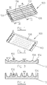
- Figures 1 and 2 show a ceramic reflector according to the invention.
- Figure 3 shows a cross section of the ceramic reflector of figures 1 and 2 along plane III-III.
- Figure 4 shows a cross section of the ceramic reflector of figures 1 and 2 along plane IV-IV.
- the ceramic reflector 100 comprises a plurality of juxtaposed elongated concave reflector bodies 102.
- Each of the at least one elongated concave reflector bodies comprises an elongated bottom section 104 and two elongated upstanding walls 106. Neighbouring elongated concave reflector bodies have a common elongated upstanding wall.
- the reflector bodies 102 comprise at their deepest level a number of through holes 108 provided for the flow of cooling air. This way, the back of the ceramic reflector can be put in overpressure such that cooling air flows through the through holes 108 in order to cool the IR lamps.
- the bottom 110 of the exemplary ceramic reflector is flat.
- Each of the elongated concave reflector bodies is provided for containing one IR lamp and for reflecting the IR radiation from the IR lamp.
- the cross sections of the ceramic reflector represented in figures 3 and 4 show the position of one IR lamp 150.
- the elongated concave reflector bodies have in each cross section at both of its upstanding walls a wall height.
- the wall height is the vertical distance between the deepest level of the bottom section of the reflector body and the highest level of the upstanding wall.
- the wall height W e is at both longitudinal ends of each reflector body at both upstanding walls larger than the wall height W m1 , W m2 in the middle section of the elongated concave reflector body.
- W e equals 15.75 mm
- W m1 equals 2.95 mm
- W m2 equals 7.25 mm.
- the wall height is at both upstanding walls over a length L 8.5 mm larger than in the middle section of the elongated concave reflector body.
- the ceramic reflector of figures 1 and 2 can be manufactured as one single sintered or fused ceramic part; e.g. out of silica.
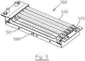
- FIG. 5 shows an electrical IR emitter 500 according to the invention.
- the electrical IR emitter 500 comprises a base structure 560, a ceramic reflector 501 as in figures 1 and 2 , IR lamps 550 and ceramic supports 570.
- the IR-lamps 550 are provided in elongated concave reflector bodies.
- the ceramic reflector 550 of figure 5 comprises six elongated concave reflector bodies, in four of which an IR lamp 550 is shown.
- the ceramic reflector 501 and the ceramic supports 570 are fixed onto the base structure 560 without direct contact between the ceramic reflector and the ceramic supports.
- the IR lamps 550 are electrically connected to electrical connectors in the ceramic supports 570.
- the electrical connectors of the IR lamps are provided outside the longitudinal ends of the reflector bodies where the wall height is at both upstanding walls larger than in the middle section of the reflector bodies.
- the highest level of the IR-lamps is located below the wall height of the longitudinal ends of the reflector bodies where the wall height is at both upstanding walls larger than in the middle section of the reflector bodies.
- the highest level of the IR-lamp is located more distant from the deepest level of the bottom section of the reflector body than the height of the upstanding walls in the middle section of the reflector bodies.
Landscapes
- Physics & Mathematics (AREA)
- General Physics & Mathematics (AREA)
- Optics & Photonics (AREA)
- Arrangement Of Elements, Cooling, Sealing, Or The Like Of Lighting Devices (AREA)
- Non-Portable Lighting Devices Or Systems Thereof (AREA)
Claims (12)
- Keramikreflektor für mindestens eine IR-Lampe,
umfassend mindestens einen länglichen konkaven Reflektorkörper (102),
wobei jeder von den mindestens einen länglichen konkaven Reflektorkörpern (102) einen länglichen unteren Abschnitt (104) und zwei längliche aufrechte Wände (106) umfasst,
wobei jeder von den länglichen konkaven Reflektorkörpern zum Enthalten von mindestens einer IR-Lampe und zum Reflektieren des IR-Lichts von der mindestens einen IR-Lampe vorgesehen ist,
wobei jeder längliche konkave Reflektorkörper in jedem Querschnitt an beiden seiner aufrechten Wände (106) eine Wandhöhe aufweist, wobei die Wandhöhe der vertikale Abstand zwischen dem tiefsten Niveau des unteren Abschnitts (104) des Reflektorkörpers und dem höchsten Niveau der aufrechten Wand (106) ist,
dadurch gekennzeichnet, dass
an einem oder an beiden Längsenden von mindestens einem Reflektorkörper die Wandhöhe an beiden aufrechten Wänden größer als in dem mittleren Abschnitt des länglichen konkaven Reflektorkörpers ist. - Keramikreflektor nach Anspruch 1,
umfassend mehrere nebeneinanderliegende längliche konkave Reflektorkörper (102),
wobei jeder von den mindestens einen länglichen konkaven Reflektorkörpern (102) einen länglichen unteren Abschnitt (104) und zwei längliche aufrechte Wände (106) umfasst,
wobei jeder von den länglichen konkaven Reflektorkörpern zum Enthalten von mindestens einer IR-Lampe und zum Reflektieren des IR-Lichts von der mindestens einen IR-Lampe vorgesehen ist,
wobei jeder längliche konkave Reflektorkörper in jedem Querschnitt an beiden seiner aufrechten Wände (106) eine Wandhöhe aufweist, wobei die Wandhöhe der vertikale Abstand zwischen dem tiefsten Niveau des unteren Abschnitts (104) des Refektorkörpers und dem höchsten Niveau der aufrechten Wand ist,
wobei an einem oder an beiden Längsenden von jedem Reflektorkörper die Wandhöhe an beiden aufrechten Wänden (106) größer ist als in dem mittleren Abschnitt des länglichen konkaven Reflektorkörpers. - Keramikreflektor nach einem der vorhergehenden Ansprüche, wobei der mindestens eine längliche konkave Reflektorkörper an seinem tiefsten Niveau eine Anzahl von Durchgangslöchern (108) umfasst, die für die Strömung von Kühlluft vorgesehen sind.
- Keramikreflektor nach einem der vorhergehenden Ansprüche, wobei an einem oder an beiden Längsenden von mindestens einem Reflektorkörper die Wandhöhe an beiden aufrechten Wänden (106) über mindestens eine Länge von 6 mm größer als in dem mittleren Abschnitt des länglichen konkaven Reflektorkörpers ist.
- Keramikreflektor nach einem der vorhergehenden Ansprüche, wobei an einem oder an beiden Längsenden von mindestens einem Reflektorkörper die Wandhöhe an beiden aufrechten Wänden (106) mindestens 7 mm, und vorzugsweise mindestens 10 mm, größer als in dem mittleren Abschnitt des länglichen konkaven Reflektorkörpers ist.
- Keramikreflektor nach einem der Ansprüche 2 - 5,
wobei benachbarte längliche konkave Reflektorkörper eine gemeinsame längliche aufrechte Wand aufweisen. - Keramikreflektor nach einem der vorhergehenden Ansprüche, wobei der Boden (110) des Keramikreflektors flach ist, wobei mit Boden (110) des Reflektors die Seite des Reflektors gemeint ist, die der Seite, wo die IR-Lampe oder IR-Lampen vorgesehen sein können, entgegengesetzt ist.
- Keramikreflektor nach einem der vorhergehenden Ansprüche, wobei der Keramikreflektor ein einziges gesintertes oder geschmolzenes Keramikteil ist.
- Elektrischer IR-Emitter (500), umfassend:- einen Keramikreflektor nach einem der vorhergehenden Ansprüche und- eine oder mehr als eine IR-Lampe, wobei die IR-Lampe oder IR-Lampen in den länglichen konkaven Reflektorkörpern vorgesehen sind,
wobei die elektrischen Verbinder der IR-Lampen an oder außerhalb der Längsenden der Reflektorkörper vorgesehen sind, wo die Wandhöhe an beiden aufrechten Wänden (106) größer als in dem mittleren Abschnitt der Reflektorkörper ist. - Elektrischer IR-Emitter (500) nach Anspruch 9, wobei das höchste Niveau der IR-Lampe sich unterhalb der Wandhöhe der Längsenden der Reflektorkörper befindet, wo die Wandhöhe an beiden aufrechten Wänden (106) größer als in dem mittleren Abschnitt der Reflektorkörper ist, wobei mit dem höchsten Niveau der IR-Lampe das Niveau der IR-Lampe gemeint ist, wo der vertikale Abstand von dem tiefsten Niveau des unteren Abschnitts (104) des Reflektorkörpers am größten ist.
- Elektrischer IR-Emitter (500) nach einem der Ansprüche 9 - 10, wobei das höchste Niveau der IR-Lampe sich weiter von dem tiefsten Niveau des unteren Abschnitts (104) des Reflektorkörpers entfernt befindet als die Höhe der aufrechten Wände (106) in dem mittleren Abschnitt der Reflektorkörper, wobei mit dem höchsten Niveau der IR-Lampe das Niveau der IR-Lampe gemeint ist, wo der vertikale Abstand von dem tiefsten Niveau des unteren Abschnitts (104) des Reflektorkörpers am größten ist.
- Elektrischer IR-Emitter (500) nach einem der Ansprüche 9 - 11,
wobei der elektrische IR-Emitter (500) eine Basisstruktur (560) und mehrere Keramikstützen (570) umfasst,
wobei der Keramikreflektor und die mehreren Keramikstützen (570) an der Basisstruktur (560) ohne direkten Kontakt zwischen dem Keramikreflektor und den Keramikstützen (570) befestigt sind, wobei die elektrischen Verbinder der IR-Lampen elektrisch mit elektrischen Verbindern in den Keramikstützen (570) verbunden sind.
Applications Claiming Priority (2)
| Application Number | Priority Date | Filing Date | Title |
|---|---|---|---|
| EP17290007 | 2017-01-24 | ||
| PCT/EP2018/050393 WO2018137917A1 (en) | 2017-01-24 | 2018-01-09 | Ceramic reflector for infrared lamps |
Publications (2)
| Publication Number | Publication Date |
|---|---|
| EP3574708A1 EP3574708A1 (de) | 2019-12-04 |
| EP3574708B1 true EP3574708B1 (de) | 2020-09-09 |
Family
ID=57965863
Family Applications (1)
| Application Number | Title | Priority Date | Filing Date |
|---|---|---|---|
| EP18700117.7A Active EP3574708B1 (de) | 2017-01-24 | 2018-01-09 | Keramikreflektor für infrarotlampen |
Country Status (4)
| Country | Link |
|---|---|
| US (1) | US11397288B2 (de) |
| EP (1) | EP3574708B1 (de) |
| CN (1) | CN110268799B (de) |
| WO (1) | WO2018137917A1 (de) |
Families Citing this family (1)
| Publication number | Priority date | Publication date | Assignee | Title |
|---|---|---|---|---|
| FR3103260B1 (fr) * | 2019-11-15 | 2021-11-26 | Solaronics Sa | Emetteur de rayonnement infra-rouge |
Family Cites Families (26)
| Publication number | Priority date | Publication date | Assignee | Title |
|---|---|---|---|---|
| US1479819A (en) * | 1922-02-02 | 1924-01-08 | Anne J Kluever | Heater |
| US3114822A (en) * | 1960-08-23 | 1963-12-17 | Harry B Boland | Industrial heat treating device |
| US3862397A (en) * | 1972-03-24 | 1975-01-21 | Applied Materials Tech | Cool wall radiantly heated reactor |
| US3763349A (en) * | 1972-07-17 | 1973-10-02 | Watlow Electric Manuf Co | Radiant heater with improved radiating bars and mounting means therefor |
| US3836751A (en) * | 1973-07-26 | 1974-09-17 | Applied Materials Inc | Temperature controlled profiling heater |
| US4450343A (en) * | 1981-10-19 | 1984-05-22 | Dundon Gerard M | High output, long duration, quick response, radiant electrical heater |
| JPS59928A (ja) * | 1982-06-25 | 1984-01-06 | Ushio Inc | 光加熱装置 |
| DE8401528U1 (de) * | 1984-01-20 | 1985-05-15 | Infrarödteknik AB, 46200 Vänersborg | Infrarotstrahlvorrichtung |
| US4678959A (en) * | 1984-11-15 | 1987-07-07 | U.S. Philips Corporation | Device for cooling the pinch seal of an electric lamp, and an electric lamp and an irradiation apparatus provided with this cooling device |
| US4975561A (en) * | 1987-06-18 | 1990-12-04 | Epsilon Technology Inc. | Heating system for substrates |
| US5790752A (en) * | 1995-12-20 | 1998-08-04 | Hytec Flow Systems | Efficient in-line fluid heater |
| US6393211B1 (en) | 1997-04-28 | 2002-05-21 | Les Importations Dmd Inc. | Heat radiator assembly |
| US6242717B1 (en) | 1999-08-30 | 2001-06-05 | Lucent Technologies Inc. | Removable reflector rack for an ultraviolet curing oven |
| US6361301B1 (en) * | 2000-02-21 | 2002-03-26 | Plastipak Packaging, Inc. | Heater assembly for blow molding plastic preforms |
| US20030221686A1 (en) * | 2002-05-29 | 2003-12-04 | Farshid Ahmady | Variable high intensity infrared heater |
| US7030543B2 (en) * | 2004-02-24 | 2006-04-18 | Osram Sylvania Inc. | Reflector lamp having reduced seal temperature |
| US8278805B2 (en) | 2004-09-16 | 2012-10-02 | Speziallampenfabrik Dr. Fischer Gmbh | Lamp assembly with lamp and reflector |
| US8233784B2 (en) * | 2006-06-16 | 2012-07-31 | Tempco Electric Heater Corporation | Radiant heater |
| US7805064B2 (en) | 2006-06-26 | 2010-09-28 | TP Solar, Inc. (Corporation of CA, USA) | Rapid thermal firing IR conveyor furnace having high intensity heating section |
| US8571396B2 (en) * | 2006-06-26 | 2013-10-29 | Tp Solar, Inc. | Rapid thermal firing IR conveyor furnace having high intensity heating section |
| WO2011036593A1 (en) | 2009-09-23 | 2011-03-31 | Speziallampenfabrik Dr. Fischer Gmbh | Heating installation and reflecting device for a heating installation. |
| CN103929951B (zh) * | 2011-09-26 | 2017-06-09 | 未来农业控股协会 | 加热灯 |
| CN103648197A (zh) * | 2013-12-11 | 2014-03-19 | 中国电子科技集团公司第二研究所 | 高均匀性多组工件共晶炉加热平台 |
| TWI537083B (zh) | 2014-03-18 | 2016-06-11 | 永發欣業有限公司 | 加熱單元及包含其之真空焊接機 |
| CN104595863B (zh) * | 2014-12-02 | 2018-02-13 | 北京卫星环境工程研究所 | 用于真空低温环境下的红外灯具 |
| CN104985834B (zh) * | 2015-05-29 | 2018-09-07 | 武汉大学 | 一种用于高速纤维铺放中的红外波加热系统 |
-
2018
- 2018-01-09 CN CN201880008361.7A patent/CN110268799B/zh active Active
- 2018-01-09 EP EP18700117.7A patent/EP3574708B1/de active Active
- 2018-01-09 WO PCT/EP2018/050393 patent/WO2018137917A1/en not_active Ceased
- 2018-01-09 US US16/476,394 patent/US11397288B2/en active Active
Non-Patent Citations (1)
| Title |
|---|
| None * |
Also Published As
| Publication number | Publication date |
|---|---|
| US20200049867A1 (en) | 2020-02-13 |
| WO2018137917A1 (en) | 2018-08-02 |
| US11397288B2 (en) | 2022-07-26 |
| CN110268799A (zh) | 2019-09-20 |
| CN110268799B (zh) | 2021-08-27 |
| EP3574708A1 (de) | 2019-12-04 |
Similar Documents
| Publication | Publication Date | Title |
|---|---|---|
| CN106030191B (zh) | 半导体管形灯、用于半导体管形灯的管和制造方法 | |
| EP2707652B1 (de) | Hochenergetische led-beleuchtungseinheit | |
| EP2929239B1 (de) | Flache beleuchtungsvorrichtung | |
| CN101500452B (zh) | 辐射加热器 | |
| US9000333B2 (en) | Heating installation and reflecting device for a heating installation | |
| KR102731777B1 (ko) | 발열구조체를 구비하는 소성로용 대차 및 이를 포함하는 소성로 | |
| CN106482031A (zh) | 烤箱灯 | |
| US11397288B2 (en) | Ceramic reflector for infrared lamps | |
| US20160223184A1 (en) | Lamp | |
| TWI833959B (zh) | 加熱裝置及加熱方法 | |
| CN107848028B (zh) | 熔融金属装卸装置加热系统 | |
| KR20120052102A (ko) | 부분적인 온도 조절이 가능한 반도체 제조용 적층형 스테이지 히터 | |
| ITMI20121855A1 (it) | Sistema di riscaldamento per forno per preforme | |
| US11147129B2 (en) | Industrial heater | |
| WO2018138125A1 (en) | Apparatus for heating preforms made of thermoplastic material | |
| KR102743985B1 (ko) | 온도 편차 감소용 단열부재가 구비된 소결로 | |
| JP7398107B2 (ja) | 加熱装置および加熱方法 | |
| JP3358511B2 (ja) | 糸用加熱装置 | |
| KR101499056B1 (ko) | 내부 오염 방지형 진공 증발원 | |
| KR102701253B1 (ko) | 바닥판에 슬릿이 형성되는 전기 레인지 | |
| JP2017003169A (ja) | 赤外線ヒーター及び赤外線処理装置 | |
| JP7079042B2 (ja) | 加熱装置および加熱方法 | |
| KR101811783B1 (ko) | 가열부재의 파손이 방지되도록 구성되는 디스플레이 패널 열처리장치 | |
| KR20240007611A (ko) | 구역-기반 가열 요소 | |
| JPS6328189Y2 (de) |
Legal Events
| Date | Code | Title | Description |
|---|---|---|---|
| STAA | Information on the status of an ep patent application or granted ep patent |
Free format text: STATUS: UNKNOWN |
|
| STAA | Information on the status of an ep patent application or granted ep patent |
Free format text: STATUS: THE INTERNATIONAL PUBLICATION HAS BEEN MADE |
|
| PUAI | Public reference made under article 153(3) epc to a published international application that has entered the european phase |
Free format text: ORIGINAL CODE: 0009012 |
|
| STAA | Information on the status of an ep patent application or granted ep patent |
Free format text: STATUS: REQUEST FOR EXAMINATION WAS MADE |
|
| 17P | Request for examination filed |
Effective date: 20190621 |
|
| AK | Designated contracting states |
Kind code of ref document: A1 Designated state(s): AL AT BE BG CH CY CZ DE DK EE ES FI FR GB GR HR HU IE IS IT LI LT LU LV MC MK MT NL NO PL PT RO RS SE SI SK SM TR |
|
| AX | Request for extension of the european patent |
Extension state: BA ME |
|
| DAV | Request for validation of the european patent (deleted) | ||
| DAX | Request for extension of the european patent (deleted) | ||
| GRAP | Despatch of communication of intention to grant a patent |
Free format text: ORIGINAL CODE: EPIDOSNIGR1 |
|
| STAA | Information on the status of an ep patent application or granted ep patent |
Free format text: STATUS: GRANT OF PATENT IS INTENDED |
|
| INTG | Intention to grant announced |
Effective date: 20200528 |
|
| GRAS | Grant fee paid |
Free format text: ORIGINAL CODE: EPIDOSNIGR3 |
|
| GRAA | (expected) grant |
Free format text: ORIGINAL CODE: 0009210 |
|
| STAA | Information on the status of an ep patent application or granted ep patent |
Free format text: STATUS: THE PATENT HAS BEEN GRANTED |
|
| AK | Designated contracting states |
Kind code of ref document: B1 Designated state(s): AL AT BE BG CH CY CZ DE DK EE ES FI FR GB GR HR HU IE IS IT LI LT LU LV MC MK MT NL NO PL PT RO RS SE SI SK SM TR |
|
| REG | Reference to a national code |
Ref country code: GB Ref legal event code: FG4D |
|
| REG | Reference to a national code |
Ref country code: AT Ref legal event code: REF Ref document number: 1313206 Country of ref document: AT Kind code of ref document: T Effective date: 20200915 Ref country code: CH Ref legal event code: EP |
|
| REG | Reference to a national code |
Ref country code: DE Ref legal event code: R096 Ref document number: 602018007687 Country of ref document: DE |
|
| REG | Reference to a national code |
Ref country code: IE Ref legal event code: FG4D |
|
| REG | Reference to a national code |
Ref country code: LT Ref legal event code: MG4D |
|
| PG25 | Lapsed in a contracting state [announced via postgrant information from national office to epo] |
Ref country code: BG Free format text: LAPSE BECAUSE OF FAILURE TO SUBMIT A TRANSLATION OF THE DESCRIPTION OR TO PAY THE FEE WITHIN THE PRESCRIBED TIME-LIMIT Effective date: 20201209 Ref country code: LT Free format text: LAPSE BECAUSE OF FAILURE TO SUBMIT A TRANSLATION OF THE DESCRIPTION OR TO PAY THE FEE WITHIN THE PRESCRIBED TIME-LIMIT Effective date: 20200909 Ref country code: FI Free format text: LAPSE BECAUSE OF FAILURE TO SUBMIT A TRANSLATION OF THE DESCRIPTION OR TO PAY THE FEE WITHIN THE PRESCRIBED TIME-LIMIT Effective date: 20200909 Ref country code: SE Free format text: LAPSE BECAUSE OF FAILURE TO SUBMIT A TRANSLATION OF THE DESCRIPTION OR TO PAY THE FEE WITHIN THE PRESCRIBED TIME-LIMIT Effective date: 20200909 Ref country code: HR Free format text: LAPSE BECAUSE OF FAILURE TO SUBMIT A TRANSLATION OF THE DESCRIPTION OR TO PAY THE FEE WITHIN THE PRESCRIBED TIME-LIMIT Effective date: 20200909 Ref country code: NO Free format text: LAPSE BECAUSE OF FAILURE TO SUBMIT A TRANSLATION OF THE DESCRIPTION OR TO PAY THE FEE WITHIN THE PRESCRIBED TIME-LIMIT Effective date: 20201209 |
|
| REG | Reference to a national code |
Ref country code: AT Ref legal event code: MK05 Ref document number: 1313206 Country of ref document: AT Kind code of ref document: T Effective date: 20200909 |
|
| REG | Reference to a national code |
Ref country code: NL Ref legal event code: MP Effective date: 20200909 |
|
| PG25 | Lapsed in a contracting state [announced via postgrant information from national office to epo] |
Ref country code: LV Free format text: LAPSE BECAUSE OF FAILURE TO SUBMIT A TRANSLATION OF THE DESCRIPTION OR TO PAY THE FEE WITHIN THE PRESCRIBED TIME-LIMIT Effective date: 20200909 Ref country code: PL Free format text: LAPSE BECAUSE OF FAILURE TO SUBMIT A TRANSLATION OF THE DESCRIPTION OR TO PAY THE FEE WITHIN THE PRESCRIBED TIME-LIMIT Effective date: 20200909 Ref country code: RS Free format text: LAPSE BECAUSE OF FAILURE TO SUBMIT A TRANSLATION OF THE DESCRIPTION OR TO PAY THE FEE WITHIN THE PRESCRIBED TIME-LIMIT Effective date: 20200909 |
|
| PG25 | Lapsed in a contracting state [announced via postgrant information from national office to epo] |
Ref country code: CZ Free format text: LAPSE BECAUSE OF FAILURE TO SUBMIT A TRANSLATION OF THE DESCRIPTION OR TO PAY THE FEE WITHIN THE PRESCRIBED TIME-LIMIT Effective date: 20200909 Ref country code: PT Free format text: LAPSE BECAUSE OF FAILURE TO SUBMIT A TRANSLATION OF THE DESCRIPTION OR TO PAY THE FEE WITHIN THE PRESCRIBED TIME-LIMIT Effective date: 20210111 Ref country code: RO Free format text: LAPSE BECAUSE OF FAILURE TO SUBMIT A TRANSLATION OF THE DESCRIPTION OR TO PAY THE FEE WITHIN THE PRESCRIBED TIME-LIMIT Effective date: 20200909 Ref country code: EE Free format text: LAPSE BECAUSE OF FAILURE TO SUBMIT A TRANSLATION OF THE DESCRIPTION OR TO PAY THE FEE WITHIN THE PRESCRIBED TIME-LIMIT Effective date: 20200909 Ref country code: SM Free format text: LAPSE BECAUSE OF FAILURE TO SUBMIT A TRANSLATION OF THE DESCRIPTION OR TO PAY THE FEE WITHIN THE PRESCRIBED TIME-LIMIT Effective date: 20200909 |
|
| PG25 | Lapsed in a contracting state [announced via postgrant information from national office to epo] |
Ref country code: IS Free format text: LAPSE BECAUSE OF FAILURE TO SUBMIT A TRANSLATION OF THE DESCRIPTION OR TO PAY THE FEE WITHIN THE PRESCRIBED TIME-LIMIT Effective date: 20210109 Ref country code: ES Free format text: LAPSE BECAUSE OF FAILURE TO SUBMIT A TRANSLATION OF THE DESCRIPTION OR TO PAY THE FEE WITHIN THE PRESCRIBED TIME-LIMIT Effective date: 20200909 Ref country code: AT Free format text: LAPSE BECAUSE OF FAILURE TO SUBMIT A TRANSLATION OF THE DESCRIPTION OR TO PAY THE FEE WITHIN THE PRESCRIBED TIME-LIMIT Effective date: 20200909 Ref country code: AL Free format text: LAPSE BECAUSE OF FAILURE TO SUBMIT A TRANSLATION OF THE DESCRIPTION OR TO PAY THE FEE WITHIN THE PRESCRIBED TIME-LIMIT Effective date: 20200909 |
|
| REG | Reference to a national code |
Ref country code: DE Ref legal event code: R097 Ref document number: 602018007687 Country of ref document: DE |
|
| PG25 | Lapsed in a contracting state [announced via postgrant information from national office to epo] |
Ref country code: SK Free format text: LAPSE BECAUSE OF FAILURE TO SUBMIT A TRANSLATION OF THE DESCRIPTION OR TO PAY THE FEE WITHIN THE PRESCRIBED TIME-LIMIT Effective date: 20200909 |
|
| PLBE | No opposition filed within time limit |
Free format text: ORIGINAL CODE: 0009261 |
|
| STAA | Information on the status of an ep patent application or granted ep patent |
Free format text: STATUS: NO OPPOSITION FILED WITHIN TIME LIMIT |
|
| 26N | No opposition filed |
Effective date: 20210610 |
|
| PG25 | Lapsed in a contracting state [announced via postgrant information from national office to epo] |
Ref country code: MC Free format text: LAPSE BECAUSE OF FAILURE TO SUBMIT A TRANSLATION OF THE DESCRIPTION OR TO PAY THE FEE WITHIN THE PRESCRIBED TIME-LIMIT Effective date: 20200909 Ref country code: DK Free format text: LAPSE BECAUSE OF FAILURE TO SUBMIT A TRANSLATION OF THE DESCRIPTION OR TO PAY THE FEE WITHIN THE PRESCRIBED TIME-LIMIT Effective date: 20200909 |
|
| REG | Reference to a national code |
Ref country code: CH Ref legal event code: PL |
|
| PG25 | Lapsed in a contracting state [announced via postgrant information from national office to epo] |
Ref country code: LU Free format text: LAPSE BECAUSE OF NON-PAYMENT OF DUE FEES Effective date: 20210109 |
|
| REG | Reference to a national code |
Ref country code: BE Ref legal event code: MM Effective date: 20210131 |
|
| PG25 | Lapsed in a contracting state [announced via postgrant information from national office to epo] |
Ref country code: IT Free format text: LAPSE BECAUSE OF FAILURE TO SUBMIT A TRANSLATION OF THE DESCRIPTION OR TO PAY THE FEE WITHIN THE PRESCRIBED TIME-LIMIT Effective date: 20200909 |
|
| PG25 | Lapsed in a contracting state [announced via postgrant information from national office to epo] |
Ref country code: LI Free format text: LAPSE BECAUSE OF NON-PAYMENT OF DUE FEES Effective date: 20210131 Ref country code: CH Free format text: LAPSE BECAUSE OF NON-PAYMENT OF DUE FEES Effective date: 20210131 |
|
| PG25 | Lapsed in a contracting state [announced via postgrant information from national office to epo] |
Ref country code: IE Free format text: LAPSE BECAUSE OF NON-PAYMENT OF DUE FEES Effective date: 20210109 |
|
| PG25 | Lapsed in a contracting state [announced via postgrant information from national office to epo] |
Ref country code: BE Free format text: LAPSE BECAUSE OF NON-PAYMENT OF DUE FEES Effective date: 20210131 |
|
| GBPC | Gb: european patent ceased through non-payment of renewal fee |
Effective date: 20220109 |
|
| PG25 | Lapsed in a contracting state [announced via postgrant information from national office to epo] |
Ref country code: GB Free format text: LAPSE BECAUSE OF NON-PAYMENT OF DUE FEES Effective date: 20220109 |
|
| REG | Reference to a national code |
Ref country code: DE Ref legal event code: R082 Ref document number: 602018007687 Country of ref document: DE Representative=s name: CBDL PATENTANWAELTE GBR, DE Ref country code: DE Ref legal event code: R082 Ref document number: 602018007687 Country of ref document: DE Representative=s name: CBDL PATENTANWAELTE EGBR, DE |
|
| PG25 | Lapsed in a contracting state [announced via postgrant information from national office to epo] |
Ref country code: NL Free format text: LAPSE BECAUSE OF NON-PAYMENT OF DUE FEES Effective date: 20200923 Ref country code: CY Free format text: LAPSE BECAUSE OF FAILURE TO SUBMIT A TRANSLATION OF THE DESCRIPTION OR TO PAY THE FEE WITHIN THE PRESCRIBED TIME-LIMIT Effective date: 20200909 |
|
| PG25 | Lapsed in a contracting state [announced via postgrant information from national office to epo] |
Ref country code: HU Free format text: LAPSE BECAUSE OF FAILURE TO SUBMIT A TRANSLATION OF THE DESCRIPTION OR TO PAY THE FEE WITHIN THE PRESCRIBED TIME-LIMIT; INVALID AB INITIO Effective date: 20180109 Ref country code: GR Free format text: LAPSE BECAUSE OF FAILURE TO SUBMIT A TRANSLATION OF THE DESCRIPTION OR TO PAY THE FEE WITHIN THE PRESCRIBED TIME-LIMIT Effective date: 20200909 |
|
| PG25 | Lapsed in a contracting state [announced via postgrant information from national office to epo] |
Ref country code: SI Free format text: LAPSE BECAUSE OF FAILURE TO SUBMIT A TRANSLATION OF THE DESCRIPTION OR TO PAY THE FEE WITHIN THE PRESCRIBED TIME-LIMIT Effective date: 20200909 |
|
| PG25 | Lapsed in a contracting state [announced via postgrant information from national office to epo] |
Ref country code: MK Free format text: LAPSE BECAUSE OF FAILURE TO SUBMIT A TRANSLATION OF THE DESCRIPTION OR TO PAY THE FEE WITHIN THE PRESCRIBED TIME-LIMIT Effective date: 20200909 |
|
| PG25 | Lapsed in a contracting state [announced via postgrant information from national office to epo] |
Ref country code: MT Free format text: LAPSE BECAUSE OF FAILURE TO SUBMIT A TRANSLATION OF THE DESCRIPTION OR TO PAY THE FEE WITHIN THE PRESCRIBED TIME-LIMIT Effective date: 20200909 |
|
| PG25 | Lapsed in a contracting state [announced via postgrant information from national office to epo] |
Ref country code: TR Free format text: LAPSE BECAUSE OF FAILURE TO SUBMIT A TRANSLATION OF THE DESCRIPTION OR TO PAY THE FEE WITHIN THE PRESCRIBED TIME-LIMIT Effective date: 20200909 |
|
| PGFP | Annual fee paid to national office [announced via postgrant information from national office to epo] |
Ref country code: DE Payment date: 20260114 Year of fee payment: 9 |
|
| PGFP | Annual fee paid to national office [announced via postgrant information from national office to epo] |
Ref country code: FR Payment date: 20260120 Year of fee payment: 9 |