EP3574283B1 - Verfahren und system zur messung der dicke einer beschichtung - Google Patents
Verfahren und system zur messung der dicke einer beschichtung Download PDFInfo
- Publication number
- EP3574283B1 EP3574283B1 EP18704288.2A EP18704288A EP3574283B1 EP 3574283 B1 EP3574283 B1 EP 3574283B1 EP 18704288 A EP18704288 A EP 18704288A EP 3574283 B1 EP3574283 B1 EP 3574283B1
- Authority
- EP
- European Patent Office
- Prior art keywords
- calibration
- thz
- thickness
- data
- layers
- Prior art date
- Legal status (The legal status is an assumption and is not a legal conclusion. Google has not performed a legal analysis and makes no representation as to the accuracy of the status listed.)
- Active
Links
Images


Classifications
-
- G—PHYSICS
- G01—MEASURING; TESTING
- G01B—MEASURING LENGTH, THICKNESS OR SIMILAR LINEAR DIMENSIONS; MEASURING ANGLES; MEASURING AREAS; MEASURING IRREGULARITIES OF SURFACES OR CONTOURS
- G01B11/00—Measuring arrangements characterised by the use of optical techniques
- G01B11/02—Measuring arrangements characterised by the use of optical techniques for measuring length, width or thickness
- G01B11/06—Measuring arrangements characterised by the use of optical techniques for measuring length, width or thickness for measuring thickness ; e.g. of sheet material
- G01B11/0616—Measuring arrangements characterised by the use of optical techniques for measuring length, width or thickness for measuring thickness ; e.g. of sheet material of coating
- G01B11/0625—Measuring arrangements characterised by the use of optical techniques for measuring length, width or thickness for measuring thickness ; e.g. of sheet material of coating with measurement of absorption or reflection
- G01B11/0633—Measuring arrangements characterised by the use of optical techniques for measuring length, width or thickness for measuring thickness ; e.g. of sheet material of coating with measurement of absorption or reflection using one or more discrete wavelengths
-
- G—PHYSICS
- G01—MEASURING; TESTING
- G01B—MEASURING LENGTH, THICKNESS OR SIMILAR LINEAR DIMENSIONS; MEASURING ANGLES; MEASURING AREAS; MEASURING IRREGULARITIES OF SURFACES OR CONTOURS
- G01B11/00—Measuring arrangements characterised by the use of optical techniques
- G01B11/02—Measuring arrangements characterised by the use of optical techniques for measuring length, width or thickness
- G01B11/06—Measuring arrangements characterised by the use of optical techniques for measuring length, width or thickness for measuring thickness ; e.g. of sheet material
- G01B11/0616—Measuring arrangements characterised by the use of optical techniques for measuring length, width or thickness for measuring thickness ; e.g. of sheet material of coating
- G01B11/0625—Measuring arrangements characterised by the use of optical techniques for measuring length, width or thickness for measuring thickness ; e.g. of sheet material of coating with measurement of absorption or reflection
-
- G—PHYSICS
- G01—MEASURING; TESTING
- G01B—MEASURING LENGTH, THICKNESS OR SIMILAR LINEAR DIMENSIONS; MEASURING ANGLES; MEASURING AREAS; MEASURING IRREGULARITIES OF SURFACES OR CONTOURS
- G01B11/00—Measuring arrangements characterised by the use of optical techniques
- G01B11/02—Measuring arrangements characterised by the use of optical techniques for measuring length, width or thickness
- G01B11/026—Measuring arrangements characterised by the use of optical techniques for measuring length, width or thickness by measuring distance between sensor and object
-
- G—PHYSICS
- G01—MEASURING; TESTING
- G01B—MEASURING LENGTH, THICKNESS OR SIMILAR LINEAR DIMENSIONS; MEASURING ANGLES; MEASURING AREAS; MEASURING IRREGULARITIES OF SURFACES OR CONTOURS
- G01B17/00—Measuring arrangements characterised by the use of infrasonic, sonic or ultrasonic vibrations
-
- G—PHYSICS
- G01—MEASURING; TESTING
- G01N—INVESTIGATING OR ANALYSING MATERIALS BY DETERMINING THEIR CHEMICAL OR PHYSICAL PROPERTIES
- G01N21/00—Investigating or analysing materials by the use of optical means, i.e. using sub-millimetre waves, infrared, visible or ultraviolet light
- G01N21/17—Systems in which incident light is modified in accordance with the properties of the material investigated
- G01N21/25—Colour; Spectral properties, i.e. comparison of effect of material on the light at two or more different wavelengths or wavelength bands
- G01N21/31—Investigating relative effect of material at wavelengths characteristic of specific elements or molecules, e.g. atomic absorption spectrometry
- G01N21/35—Investigating relative effect of material at wavelengths characteristic of specific elements or molecules, e.g. atomic absorption spectrometry using infrared light
- G01N21/3581—Investigating relative effect of material at wavelengths characteristic of specific elements or molecules, e.g. atomic absorption spectrometry using infrared light using far infrared light; using Terahertz radiation
-
- G—PHYSICS
- G01—MEASURING; TESTING
- G01N—INVESTIGATING OR ANALYSING MATERIALS BY DETERMINING THEIR CHEMICAL OR PHYSICAL PROPERTIES
- G01N33/00—Investigating or analysing materials by specific methods not covered by groups G01N1/00 - G01N31/00
- G01N33/26—Oils; Viscous liquids; Paints; Inks
- G01N33/32—Paints; Inks
Definitions
- Terahertz radiation is a non-invasive method of determining the internal structure of an object and the thickness of its layers.
- the terahertz time-domain waveform reflected from such a stack of thin films can be calculated rapidly using a matrix formalism of Fresnel equations.
- the inverse problem of determining the optical response and/or thickness of the coating(s) and/or substrate from a known (measured or simulated) reflection cannot, like most inverse problem, be solved directly by analytical means but instead requires a numerical approach in which different combinations of the system parameters (thickness and optical response) are tested until a combination is found that results in a good match between the corresponding calculated signal and the known signal.
- Numerical optimisation techniques can be employed to efficiently search the multidimensional solution space to find a combination that minimises, in a least squares sense, the difference between simulated and known signals.
- the problem of unambiguously determining the values of unknown coating properties is made difficult because the information content of the terahertz signal reflected from a stack of coatings is limited because 1) the thickness of individual relevant coatings (e.g. automotive or aircraft paint layers) can be on the scale of or indeed below the wavelength of the incident terahertz light; and 2) neighbouring coating layers may exhibit limited contrast (in terms of the refractive index of each coating material).
- the first consideration means that the material refractive index determined from a thick sample of a material may not be representative of the refractive index of the same material applied at a lower thickness.
- TPI terahertz pulsed imaging
- DE102015107616 describes a method and a device for determining the layer thicknesses of a sample with a known plurality of N superimposed layers, wherein both the index of refraction and the index of absorption can be approximated by a constant value for each layer over the frequency bandwidth of the RF radiation used.
- the above embodiment allow the problem of determining best-fit parameters values to synthesize a THz waveform to be simplified if the dimension and size of the solution space to be explored (by least squares minimisation) can be reduced, by applying constraints (and/or upper and lower bounds) on the possible values for the unknown quantities (thickness and refractive index).
- the problem of calculating individual coating thickness is greatly reduced if the optical response (refractive index) of all coatings and substrate are known in advance.
- the thickness of individual coating layers can be calculated using a local optimisation routine to minimise the difference between the measured and simulated signals.
- the system determines that the search limits of one or more of the optical parameters are zero. In this case, for the optical parameters with zero search limits, the optical parameters remain constant during the fitting of the sample data.
- the calibration analysis comprises selecting preferred refractive index models from data from a first set of calibration samples and determining initial values and search limits of optical parameters from data from a second set of calibration samples.
- the first set of calibration samples may be samples with a substrate and a single coating layer and the second set of calibration samples may have a substrate and the said plurality of coating layers.
- the first set of samples and the second set of samples may be provided on separate substrates to each other and also to the layers which are to be analysed.
- the said plurality of coating layers are provided on an object and second set of calibration samples are areas of the said object different from the area where the THz radiation is used to measure the said plurality of coating layers.
- the object is a vehicle
- the second set of calibration samples may be a different part or area of the vehicle to the part that is to be analysed
- the method further comprises measuring a set of calibration samples using THz radiation in the range 0.01 THz to 10 THz, and making a time domain measurement of the reflected radiation to produce said data.
- the calibration analysis may comprise receiving calibration data comprising a time domain measurement of THz radiation in the range 0.01 THz to 10 THz reflected from the said calibration samples and fitting a synthesised waveform to said data.
- the calibration model treats external measurements as approximate and finds the optical model which best fits the calibration measurements within the approximate thicknesses of the alternative modality.
- 'external measurements' and 'alternative modality' refer to thickness measurements made by independent means (e.g. ultrasonic thickness gauge or preferably optical microscopy).
- Independent measurements of individual coating layer thickness are made on both sets of panels used for calibration: single-layer panels and multi-layer panels.
- the thickness measurements are used to guide the minimisation search routines used by both single-layer and multi-layer calibration routines in order 1) to determine the optimum model to describe the refractive index of each coating layer and 2) to determine the initial values and search ranges of each parameter of said optical models.
- Single-layer calibration utilises a global optimisation search routine that requires upper and lower bounds to be defined for all model parameters (optical models and layer thicknesses).
- the global search routine tests combinations of parameter values that starts by generating random values that lie within these upper/lower bounds.
- a total thickness gauge e.g. Elcometer
- the measured thickness of single-layer panels need not be as accurate as measurements of individual coating layers made on multi-layer panels.
- Multi-layer calibration uses a local optimisation search routine to find the set of model parameter values (and search ranges) that can produce coating thicknesses that best match the independently measured coating thicknesses.
- the local search routine is initialised by setting the coating thicknesses to those values provided by independent measurements. Because of the uncertainty that exists on independent thickness measurements, the coating thickness parameters are permitted to deviate during local optimisation by an amount determined by the uncertainty of independent thickness measurements.
- the multi-layer calibration uses individual layer calibrations as a start point but which allows the optical properties to vary to find the best calibration for the full stack, the variations allowing for
- optical properties of single-layer panels include the type of model (e.g. Debye or Drude-Lorentz) that is best suited to describe the refractive index of the coating material as well as the best-fit values (and uncertainties) on the parameters that define the selected model for the measurement of the single-layer panel.
- model e.g. Debye or Drude-Lorentz
- the results of single-layer calibration for each coating present in a multi-layer calibration panel are combined and referred to as the initial multi-layer calibration.
- the multi-layer calibration routine seeks to find a set of optimum model parameter values (including uncertainties) that best describe reflection from multi-layer calibration panels (that, ideally, are produced on the same production line where vehicle coatings are applied) and that replicate the expected thicknesses (as measured by independent means) of the individual coating layers present on the multi-layer calibration panels.
- the optical model parameter values provided by single-layer calibration therefore act as the starting point from which the local optimisation routine of the multi-layer calibration routine begins.
- the thickness calculation is based on the estimated multi-layer properties but the fitting allows them to vary within narrow bounds.
- the calculation is based on which combination of thicknesses and properties gives the best fit between the simulation and actual waveforms.
- Multi-layer calibration provides initial estimates of the various parameters that describe refractive index for each coating, and also provides a search range within which those parameters are permitted to vary during the local optimisation routine that is used for coating thickness calculation.
- Optical parameter search limits are automatically determined based on the uncertainty of best-fit parameters during multi-layer calibration. If that search range is deemed to be excessive (if half the 95% confidence interval exceeds the best-fit parameter value) then any change in that parameter away from its best-fit value will have negligible impact on the calculated thicknesses and therefore the search range is set to zero. Such parameters with a zero search range are thus considered to be fixed parameters during future optimisation (to calculate coating thickness).
- the output of the fitting of the calibration data of the first samples comprises a ranked list of the refractive models. Then, when performing the calibration on the second set of samples, the first ranked refractive model is used to fit the second calibration data, and wherein if this model produces poor results, the next refractive model from the ranked list is selected.
- the refractive index models may be selected from constant refractive index, Lorentz and Debye formulations of the refractive index.
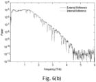
- the method is configured to taken an "internal reference" measurement.
- a measurement can be provided before any sample measure,emt as a way of continually monitoring the instrument response.
- the mirror is a movable provided in the path of the THz beam before the focus of the THz beam, the method further comprising applying a scaling function to the instrument response measured using the movable mirror in order to mimic the instrument response as if measured by a mirror placed at the focus.
- the scaling function can be derived by measuring the instrument response using a mirror positioned at the focus and comparing this with the instrument response using the movable mirror. This measurement of the scaling function can be performed offline. For example, it can be performed during general maintenance of the system. However, the actual measurement of the internal reference can be performed with each sample measurement.
- This may be done for example by determining the position of the surface of the said plurality of layers from the first increase in amplitude of the sample response over a threshold level, the first increase being measured with respect to time, and aligning the position corresponding to the sample surface of the synthesised waveform with that of the sample response.
- it may be difficult to isolate the sample surface from the sample response data. For these, the raw reflected waveform may be analysed.
- Waveform simulation includes an additional parameter, independent of those related to the coated sample (optical properties and thicknesses of coatings), to account for a reduction in measured terahertz waveform amplitude that accompanies changes in coated surface orientation relative to the terahertz beam.
- the reflected waveform amplitude In normal orientation, the reflected waveform amplitude is at a maximum, but decreases uniformly across all frequencies as the angle between terahertz beam and surface normal increases. This uniform change in waveform amplitude can be included in simulations by multiplying the simulated waveform by a constant scaling factor (with a default value of 1 at normal orientation and that decreases with increasing angle away from normal).
- a handheld sensor provides less control over positioning and orientation of the sensor compared to a robotically positioned sensor. Feedback to the operator is required to indicate when the sensor is at the preferred distance and in the preferred orientation relative to the surface of the coated body.
- the alternative modality referred to here may include an ultrasonic distance gauge (to indicate when the sensor is close to the focus of the terahertz beam), a visible laser (to indicate when the preferred orientation between sensor and coated surface has been achieved). Visual and/or audio feedback from these modalities allow the operator to know when the sensor has been positioned close to the preferred distance and orientation relative to the coated surface. More precise information on position and orientation is provided by continuous monitoring of various properties of the continuously streamed reflected terahertz waveforms.
- the differential of the measurements with respect to time can be taken to determine the speed at which the apparatus taking the measurements is moving.
- this can be viewed data acquisition filtering to ensure collection of high-quality data only, i.e. when sample is sufficiently close to focus; when sensor-surface orientation is within required tolerance; and when sensor is determined to be moving slowly, e.g. to avoid collection of noisy data due to vibrations.
- the reflected waveform is measured using a sensor, the method further comprising positioning the sensor with a measurement gauge to determine if the sensor is at a distance from the plurality of layers to allow a measurement to be performed.
- the sensor may also be aligned using an angular measuring gauge to determine if the angle of the sensor is sufficient to allow a measurement to be performed.
- additional sensors e.g. ultrasound, laser gauge, vision system
- the senor is positioned automatically via a robot arm. Before the robot can be trained to place the sensor at a defined set of locations on a vehicle body, any differences between where the robot believes the focus of the terahertz sensor to be and the actual location of that point in 3-D space must be known and should either be accounted for or removed before subsequent positioning of the sensor is undertaken.
- Different scan sequences of the robot to move the sensor focal position relative to a fixed target can be performed in order to gather data (such as the position and amplitude of the strongest reflection peak) from reflected terahertz waveforms that are then provided as input to an algorithm that calculates any differences that exist between actual and expected sensor focal position.
- Much of the above description has related to measurements at a single point. However, it is possible for a plurality of measurements to be made as a scan across the said plurality of layers.
- the scan may be a line scan or an area scan.
- These line and area scan modes can be used with a robot-mounted sensor to allow for high density mapping of a coated surface, in which the thickness over a line or area of a coated surface is mapped by moving the sensor along trajectories running parallel to the coated surface and point measurements of coating thickness made at intervals.
- the said plurality of layers are provided on a vehicle body.
- the above method can be incorporated into a vehicle spraying production line.
- the layers may comprise one or more of a clearcoat, a basecoat, a primer, an electrocoat etc.
- the method may be configured to produce the thickness result after each measurement in an on-line fashion.
- the data may be stored and the fitting of the data performed later.
- a system for determining the thickness of a plurality of coating layers comprising:
- the system may also be configured to calculate the calibration data from measurements of calibration samples, here, the system is further adapted to produce said calibration data, wherein said processor is adapted to receive first calibration data and second calibration data, said first calibration data comprising reflected THz waveforms from a first set of calibration samples and said second set of calibration data comprising reflected THz waveforms from a second set of calibration samples, the first set of calibration samples are samples with a substrate and a single coating layer and the second set of calibration samples have a substrate and a plurality of coating layers, the processor being adapted to select preferred refractive index models from data from a first set of calibration samples and determining initial values and search limits of optical parameters from data from a second set of calibration samples.
- a sensor for a THz measurement system comprising:
- the above sensor may further comprise a processor and memory, the processor being adapted retrieve from the memory a scaling function which relates the said internal reference signal to an external reference signal, the external reference signal being the signal measured when a mirror is provided at the focus of the THz radiation, said processor being adapted to reproduce an external reference signal from the internal reference signal and the scaling function.
- a sensor for a THz measurement system comprising:
- the non-THz measurement gauge is selected from an ultrasound or laser gauge.
- a sensor for a THz measurement system comprising:
- the above embodiment allow the problem of determining best-fit parameters values to synthesize a THz waveform to be simplified if the dimension and size of the solution space to be explored (by least squares minimisation) can be reduced, by applying constraints (and/or upper and lower bounds) on the possible values for the unknown quantities (thickness and refractive index).
- the problem of calculating individual coating thickness is greatly reduced if the optical response (refractive index) of all coatings and substrate are known in advance.
- the thickness of individual coating layers can be calculated using a local optimisation routine to minimise the difference between the measured and simulated signals.
- FIG 1 shows a very basic overview of a system in accordance with an embodiment of the present invention.
- the system comprises a sensor 3 that will be described in more detail with reference to figure 2 .
- the sensor is a handheld sensor which will be guided over the coated body of a vehicle 1 by a user (not shown).
- the senor is moved via computer control.
- the sensor is connected to analysis unit 5.
- FIG. 2 shows a simplified arrangement of the measurement that is made.
- the sensor 3 emits a broadband pulse of terahertz radiation 7 towards a panel 9 on the vehicle.
- the panel is a painted panel which has paint layers 11, 13 and 15.
- the terahertz radiation pulse will comprise a plurality of frequencies of radiation in the range from0.06 THz to 4 THz. In this embodiment, three layers will be discussed. However, the method can be applied to any number of layers, from 2 upwards. Systems with 5 of more layers may be analysed..
- Each layer has a boundary with the previous layer and this boundary will cause a partial reflection of some of the terahertz radiation.
- the terahertz signal reflected from each boundary will have experienced a slightly different optical path (due to the thickness and optical response of the layer through which it passed) and therefore it is possible to determine the thickness of the layers accurately by the reflected terahertz signal.
- the wavelength of the terahertz radiation is generally longer than the thickness of the layers. This makes the analysis of the signal difficult as it is not possible to simply identify the reflection from the surface of each layer.
- Figure 2 indicates the primary reflections from the four coating-coating and coating-substrate interfaces, the reflected terahertz radiation will also contain secondary and higher reflections from each interface, which will overlap with the primary reflections making straightforward analysis of the measured signal more difficult.
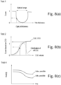
- Figure 3(a) to 3(c) shows a trace of the time-domain waveform reflected from non-metal substrate with two coatings of different refractive index (n 2 > n 1 ).
- the large thickness of coating 1 means reflection peak 1 (from air-surface interface) and reflection peak 2 (from interface between coatings 1 and 2) are easily distinguished.
- the reduced thickness of coating 1 results in a decreased separation between reflection peaks 1 and 2.
- reflection peaks 1 and 2 can no longer be seen due to thin coating 1.
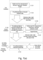
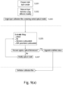
- Figure 4 shows a flowchart of the basic process which is used for determining the thickness of the paint layers. While it is possible to represent the optical properties of the individual coating layers by highly complex refractive index profiles that are parameterised by a large number of variables in order for a minimisation routine to produce a solution that approaches, or indeed achieves, zero difference between synthesised and measured signals, the fact that the measured terahertz response from the coated sample cannot support such a large number of variables corresponds to a system that is over parameterised. Such a solution might not physically represent the true response from the measured sample, thus leading to inaccuracies in best-fit parameters.
- step S101 the method first determines the preferred optical models for the individual layers present in a given multi-layered coated substrate, as well as the extent of and starting point within the multivariate solution space, i.e. initial estimates of and bounds on individual model parameters. Possible examples of how the models and their constituent parameter values may be estimated will be described with reference to figures 7 to 9 .
- the parameters will be estimated with a range of possible values and not just a single value. Once these ranges have been estimated, the algorithm will seek to derive thicknesses using parameters within these ranges.
- the parameters fall into 2 basic groups, the first group represent the thickness of the layers, the second group are the optical parameters that define the response of the layers.
- the optical parameters can be the complex refractive index, complex absorption coefficient etc.
- the optical parameters define the complex-valued frequency-dependent refractive index profile and therefore provide for absorption and or scattering losses imparted on the terahertz signal by each coating material.
- step S101 the sample is measured.
- the measurement of the sample will be described in more detail with reference to the flowchart of figure 5 .
- step S105 the parameters to be first tried will be selected in step S105.
- these will be the output of the calibration process which takes place in step S103.
- the output from the algorithm will be synthesised in step S107.
- the sample will be measured in step S107. The measurement of the sample will be described in more detail with reference to the flowchart of figure 5 .
- step S109 the synthesised output from step S107 is compared with the measured sample output from step S101.
- the error between the synthesised output and the measured output is then determined in step S111. It is then determined in step S113 if the fitting has finished.
- the end of fitting can be determined in a number of different ways. For example, the number of iterations may be a fixed number. In other embodiments, a check is made to see if the error is the minimum error. In further embodiments, other stopping criteria are used to check whether the optimisation routine has converged on a local solution. If at step S113 it is determined that the end of the fitting has not been reached, then the set of parameters are updated and a new output is synthesised in step S105. Then the process starts again. Once a solution has been determined, the system outputs the thickness of the paint layers in step S115.
- Figure 5 explains how the sample is measured in accordance with an embodiment of the invention.
- the measurement is performed by irradiating the painted car panel with a pulse of THz radiation and collecting the reflected signal.
- Figure 6(a) shows the internal configuration of terahertz sensor measuring a sample 51.
- the sample comprises a plurality of layers and is provided at the focus of the terahertz sensor.
- the terahertz sensor comprises a unit 53 which both emits and detects terahertz radiation.
- the radiation when leaving the terahertz unit is brought to focus by an optical element (e.g. a mirror) 55 at the focal plane 57 in the vicinity of the sample 51.
- an optical element e.g. a mirror
- a plane mirror (not shown) is provided at the focus 57 to allow the terahertz beam to be reflected back from the focus to the detector in unit 53.
- reference measurement is performed before every sample measurement. This can be achieved without a mirror at focus 57 by the provision of movable mirror 59.
- Movable mirror 59 is provided so that it can move into the field of the terahertz beams or move out of the field of the terahertz beams as required.
- the emitted beam is redirected towards a further plane mirror 61.
- the reflected beam then reflects back towards movable mirror 59, back towards curved mirror 55 and then into unit 53.
- this movable mirror 59 therefore allows a measurement of the instrument response to be performed without the need to place a mirror at focus 57.
- the optical path of the terahertz radiation to the movable mirror and back to the unit 53 is slightly different to that from the unit 53 to the focus 57.
- a calibration measurement can be performed which provides a scaling factor which allows the reference measurement made using the plane mirror 61, via movable mirror 59, to be modified to be the same as if the reflection came from a plane mirror at the focus 57.
- the optical configuration of the sensor 3 consists of two separate terahertz beam paths that are fed by same emitter and detector devices: a sample 51 is placed at the focus 57 of the terahertz beam along the external path and a plane mirror 61 (to record the system response) is fixed in position at the focus of the terahertz beam along the internal path.
- a reference measurement from the internal reference mirror 61 and a sample measurement from the surface of a sample (coated substrate) placed at the focus 57 of the external terahertz beam path.
- each measurement consists of the co-average of multiple individual waveforms, the number of which is dependent on signal quality and desired signal integration time in step S123.
- the simulated and measured surface reflection peaks locations are identified by analysing properties (location, width and height) of the surface reflection peak that is first identified by thresholding the deconvolved measured waveform above the full-width at half maximum signal amplitude contained in the simulated waveform. For a top-most coating with a thickness that is too thin for the individual reflection peaks from the surface and next interface to be clearly distinguished, the location of the surface reflection peak cannot be directly determined through analysis of the deconvolved waveform.
- the raw measured waveform is examined to identify the location of the strongest pre-pulse feature of the raw reference waveform the presence of which in the measured sample waveform indicates the location in the measured waveform where reflections from the measured sample surface are contained.
- the first method is attempted and if unsuccessful (because the first and second reflections cannot be clearly distinguished), the second method is used instead.
- At least one single calibration layer sample will be provided for each layer of the sample to be analysed.
- the thickness can be measured using an optical microscope, ultrasound etc.
- the data is then fitted to determine a refractive index model and an initial estimate of the optical parameters in step S133.
- the refractive index model and the parameters are then fed into the second calibration synthesis step S139.
- measurements of the thicknesses S135 of the second calibration sample and target thicknesses S137 are provided to the fitting step.
- the target thicknesses are the thicknesses that the layers are intended to be.
- the layer thicknesses are allowed to vary as its assumed that there may be an error in these calibration measurements of the thicknesses.
- the output of this step is the refractive index models to use and estimates of optical parameters with the search limits.
- step S153 the system is so that it is measuring a single layer waveform. This allows it to select a single layer characterisation configuration in step S155.
- step S157 the expected thicknesses, uncertainty number of iterations to use are entered.
- the waveform for single-layer sample is synthesised and an iterative procedure is performed to determine the optimum refractive index parameters, thickness tilt and phase in step S159. Also in this step, the model which is most suitable for examining the optical response of the single-layer sample is deduced.
- the routine examines the use of four different refractive index models ('Constant', 'Constant2', 'Debye' and 'Drude-Lorentz') with which to describe reflection from the measured single-layer sample.
- a ranking scheme (described in relation to figure 8 ) is applied to determine which of the refractive index models is best suited to describe the measurement.
- the different models are of varying complexity: the simplest (Constant) is described by two independent parameters and the most complex (Drude-Lorentz) is parameterised in terms of at least 4 arguments.
- refractive index models are purely used as an example and alternative models could be additionally or alternatively used. Additional refractive index models of greater complexity that are best suited to approximate the frequency-dependent, complex-valued refractive index of a given material could also be used. For example, the complexity of the Drude-Lorentz model could be increased by the addition of 3, 6, 9, etc. terms, that describe frequency-dependent features of the refractive index profile. Also less than four models can be used or more than four.
- the refractive index of materials are represented, it is possible to reduce to (essentially) zero the difference between measured and simulated terahertz signals.
- the resulting simulation may correspond to individual layer thicknesses that do not represent the true thickness of the sample layer(s).
- an objective of the calibration routine is to determine a numerical model that describes the refractive index profile for each material that will reproduce the measured terahertz signal reasonably well for a combination of layer thickness values that correspond to actual layer thickness values
- Figure 8 shows how the different models can be ranked in order to automatically determine which model is best suited to represent the coating layer.
- the tests are then combined to produce a score where lower scores are better.
- step S163 the parameter values and ranges are defined.
- global optimisation is applied multiple times (from different, randomly selected starting points).
- the average of the best-fit parameter values from the multiple trials are assigned as the overall best-fit parameter values for that model, while the minimum and maximum best-fit parameter values are assigned as the upper and lower search ranges for subsequent use.
- the output of the system is also the optical models ranked.
- the above system can cope with both 'thin' substrates (where the pulse returned from the rear substrate-air interface is visible) and also the 'thick' substrate (where the pulse returned from the rear substrate-air interface is not visible).
- the substrate is treated as one of the layers during the multilayer calibration.
- Metal substrates can be treated as ideal reflectors.
- the terahertz signal doesn't transmit through metal therefore there will not be a reflection from the back of a metal substrate. Therefore, there is no need to calibrate for the metal substrate. Calibration in the presence of non-metal substrates is possible on substrate in isolation for a thin layer of substrate in air; otherwise calibration done in-situ as part of multi-layer calibration
- Figure 9(b) is a panel defining the datasets that will be used in the following flow diagrams.
- Figure 9(c) is a panel showing the algorithmic operators that will be used in the following flow charts.
- Figure 9(d) is a panel detailing the operations performed in the calibration steps. It should be noted that expected and predicted thickness combinations T and P include information relating to the level of uncertainty associated with thickness values.
- Figure 9(e) and 9(f) illustrate the concepts of evaluating the quality of a given calibration as well as the relationship between single-layer calibrations and a multi-layer calibration, both of which can be generalised as a generic calibration C the solution for which can be sought using the calibration routines described here
- Figure 9(g) is a flow chart showing the multilayer calibration using the above described method.
- the Initial calibration C 0 is a single- or multi-layer calibration (S or M). All candidate calibrations C are evaluated (by calculate quality metric Q with E) that compares thicknesses produced for terahertz measurement set T with expected coating thickness set X.
- candidate calibration C i yields quality metric Q i (normalised to values ⁇ 1, where smaller values indicate higher quality.
- candidates C i are filtered to select the optimum by find minimum quality metric Qi.
- the optimum calibration C opt is that with minimum quality metric Q opt output at 605.
- step 603 candidates C i are filtered to select the optimum by find minimum quality metric Qi.
- the optimum calibration C opt is that with minimum quality metric Q opt output at 605.
- Figure 9(i) shows a variation on the calibration methods of figures 9(g) and 9(h) with recursive calibration where there is recursive generation of candidate calibrations starting from initial calibration C 0 .
- generator G operates on measurement and thickness subsets ⁇ T 1 , X 1 ⁇ that share the same layer-substrate structure but with different thickness combinations to generate a calibration with common optical properties.
- generator G operates on multiple terahertz measurements (T i ) made on coated substrate that share the same thickness combination x i . Each thickness combination has one or more associated measurements that produce a different candidate calibration C 2 .
- generator g operates on an individual terahertz measurement t corresponding to a expected thickness combination x.
- Candidate calibrations are generated for each parent calibration generated at level 2.
- the optimum calibration C opt is that from recursion level 3 with minimum quality metric Q opt .
- recursion level 3 indicates only what happens to the children of parent C 2a .
- the other calibrations generated at level 2 could each generate separate child calibrations as well. Any candidate calibrations generated on level 3 are then put forward as the list of potential candidate calibrations from which the optimum calibration is selected (by filtering based on quality metric associated with each calibration).
- the calibrations generated at previous recursion levels (0, 1 and 2) can be considered as intermediate calibrations the children of which that are generated on subsequent levels providing an improvement on the calibrations generated at preceding levels.
- the recursive calibration differs from the direct calibration of figures 9(g) and 9(h) by incorporating recursion levels 1 and 2.
- the calibration has been modified to proceed recursively and on decreasing measurement scales using grouped optimisation as explained below.
- trial calibrations were generated from an initial calibration by optimising both sample-specific parameters (those associated with the coating layer combination: thickness and optical model parameters of individual layers) and measurement-dependent parameters (surface offset and tilt factor) for one or more waveforms measured from the same location on a coated panel.
- Calibration generated by performing grouped optimisation, i.e. to multiple waveforms produces a calibration in which the uncertainty on individual parameters exceeds that of a calibration generated by optimising to each waveform individually.
- grouped optimisation parameters that are specific to individual measured waveforms (offset and tilt) are treated independently and the remaining (layer structure) parameters are treated as common to that group of waveforms (obtained from the same panel location).
- the concept of using recursive calibration on varying measurement scales allows calibration to improve with subsequent generations (through recursion) and from an improved initial calibration (by applying grouped optimisation to measured waveforms from multiple locations, i.e. from the same coating-substrate combination but with different thickness combinations, so as to find a calibration that describes reflection from those thickness combinations) and subsequently refining child generations to have smaller parameter uncertainties by reducing the measurement scale at which optimisation is applied: from coating combination level (i.e. waveforms from multiple locations); to location level (i.e. multiple waveforms from the same location); to measurement level (i.e. individual waveforms).
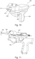
- FIG 10 shows a diagram of a sensor in accordance with an embodiment of the invention.
- the sensor 301 comprises a main body 303 with a handle 305.
- the handle 305 is similar to that of a handgun and a trigger 307 is provided for activating the sensor.
- the sensor comprises an output port 3 with an output terahertz probe 311 and an input terahertz probe 313.
- the output terahertz probe emits terahertz radiation towards the sample and it is collected via the input probe.
- Figure 11 is a cut-away diagram of the sensor of figure 10 .
- a distance sensor 331 (either a laser gauge or ultrasonic gauge) is provided under A circuit board. It can be seen that the axis of this auxiliary distance sensor 331 is aligned to intersect the THz beam 333 axis at the THz focus 335. It cannot be on axis because it would intersect with the laser alignment tool.
- the alignment laser 337 is a visible class II laser which is used in the manual version to roughly feedback to the user when the sensor is normal to the body.
- the alignment laser 337 is a visible class II laser which is used in the manually held sensor version to roughly feedback to the user when the sensor is normal to the body. This can be done because the laser is shone through a small ( ⁇ 1 mm) pinhole in a metal mirror. A clearcoat layer of the sample reflects the laser back to the sensor 301, and if a slight tilt misalignment is present, the returned beam reflects from the metal mirror and returns to the paint surface, showing a second laser spot. The operator's role is to angle the sensor in such a way as to overlap the two spots. Then the sensor 301 is approximately normal to the surface. This is also used in the robotic version to initialise teach mode. Thus two alignment tools can be used in conjunction: the distance sensor for focal distance, and the alignment laser for angle.
- the laser light from a core system (800 nm in this embodiment) is delivered through two fibre optical cables 343, (approximately 13 metres long for the robotic version and 7 metres for the handheld) to the sensor 301.
- the fibre optic cables terminate inside the THz device cartridges 339 (one emitter, one detector).
- the cartridge 339 contains a lens 341, which focusses the output from the fibre onto the photoconductive region of the semiconductor device, where the impedance of a photoconductive switch is modulated at THz frequencies, producing THz radiation.
- the radiation is coupled into free space using a silicon lens 341, whence it is focused onto the sample surface using (in this embodiment) an ellipsoidal mirror.
- the returning THz pulse is focussed by the silicon lens on the receiver cartridge 339, and generates a THz current in the receiver photoconductor.
- the THz signal is modulated electrically at the emitter at 33 kHz, and lock-in detection at the receiver results in a 33 kHz frequency voltage with amplitude proportional to the THz signal detected.
- the output is further modulated by a 15 Hz time-delay line which probes the THz signal at different points in time relative to the reference signal.
- the waveform is reconstructed by synchronising the receiver voltage data with the time domain positional output data.
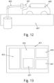
- Figure 12 is a basic schematic of the terahertz sensor for one provided on a robot arm 403. It will be appreciated the robot arm is purely for schematic purposes and in practice, the robot arm is likely to have many more degrees of freedom than those shown.
- the car body 405 to be analysed is provided on train 407. Train 407 can move the car body from a previous processing stage, for example the painting stage towards the measurement stage with sensor 401.
- Positioning the sensor such that the measured surface is at focus and normal to the direction of the terahertz beam is done by adjusting the sensor position and orientation until properties of the terahertz signal reflected from the surface (signal amplitude and offset between surface and terahertz focus) indicates that ideal orientation and position has been achieved.
- a robotic system it is possible to operate the sensor in a scan mode allows for continuous, or non-continuous, scans across a coated body.
- Extension of this concept provides the ability to perform two-dimensional mapping of a coated surface by running multiple side-by-side line scans. For each line scan, start and end points along the surface are defined by the operator. To ensure accurate positioning of the sensor along the entire line scan, the line is split into segments and the automated positioning (above) applied at each to determine ideal sensor positioning. Interpolation is applied to determine required robot movements at the remaining points on the line. For a continuous line scan, the robot is moved along the line without stopping while individual waveforms (i.e. without co-averaging) are acquired continuously.
- processing is applied to perform some level of co-averaging between groups of neighbouring waveforms before calculating thickness along the line.
- the robot is paused at pre-defined intervals along the line and a standard point measurement made at each location.
- the robotic system is provided with a set of routines for use with a robotic system to determine offsets (lateral, vertical and in orientation) between the tool centre point and the terahertz focus.
- routines consisting of a pre-programmed set of robotic movements of the sensor initially focused on a fixed reflective surface (such as the alignment plate) are considered: one to check for differences in orientation between direction of propagation of terahertz beam and the robot z-axis (by revolving the end-of-arm tool about the current definition of the z-axis); one to determine vertical offset by performing a step scan along the z-axis; and the last consisting of step scans about x- and y-axes of the tool centre point. These three scans are discussed as an example, other scan types are possible.
- the various offsets between the terahertz focus and the tool centre point can be determined and removed by either redefining the tool centre point or applying those offsets to the existing tool centre point definition for further movements of the robot.
- These routines would be used at installation of the sensor or whenever the sensor is repositioned on the end-or-arm tool, e.g. for maintenance of terahertz sensor.
- the input module 459 receives data from the sensor 401 the input is in the form of a time domain terahertz trace.
- This data is then passed to processor 455 which runs program 457.
- processor 455 runs program 457.
- the data that is passed to module 459 is processed by processor 455 and the estimated parameters and the trial ranges are saved to memory 453.
- the processor 455 calls the parameters and ranges from the memory 453. The output is provided by output module 461.
- fit thickness results are automatically compiled, and written to an output file to form a permanent record.
- the sensor 401 is controlled by processor 455 (of figure 13 ).
- Processor 455 is adapted to learn the shape and then control the sensor to move in a line along the shape following the contours of the shape such that the sensor remains a known distance from the shape.
- the system just measures the thickness at each point in the way previously described.
- an additional constraint is provided on the fitting of the thickness in that the thickness of adjacent points must vary in a continuous manner.
- the thickness fitting of each point is no longer independent, but depends on the thicknesses of the surrounding points.
- the output of the pre-scan is used to fine tune the actual line-scan in two ways:
- the line scan is then measured, using a waveform rate of typically 7.5 Hz to 30 Hz, and robot speeds of typically 10 to 200 mm per second. This yields point spacings along the car body of between 0.3 mm and 26 mm, as required.
- Each interval between adjacent waypoints is passed to a separate core for processing. Thus each interval can be fitted simultaneously.
- the process is then sequential, using the first point to calculate the second, and then the second to calculate the third, and so on.
- the process can be generalised to 2D surfaces by using a pre-scan to cover the area with intervals both horizontally and vertically, thus defining an area of polygons.
- the linear robot motion path across the panel is defined using vehicle body CAD files and subsequently modified for individual vehicle and panel positioning using a vision system and terahertz alignment scan mode.
- a measurement program then triggers terahertz waveform acquisition at beginning of the linear path, after which terahertz measurements are made at regular time intervals until the end of the linear path is reached at which point terahertz measurement is stopped.
- Coating thickness calculation is done using batch-fitting and thickness values can be displayed on-screen and/or recorded in an output data file.
- the above line scan and 2D area scan can be used to provide feedback to an operator that will allow for improvements in robot paint paths so as to optimise paint thickness uniformity across individual panels and to reduce colour matching problems between adjacent panels.
- the above workflow relates to sample measurement.
- the next workflow relates to Calibration Measurement (Handheld system)
- The is similar to the above, except in how the sensor is positioned and panels are placed.
- the procedure for analysis of the calibration data in order to generate calibration files that can be subsequently stored in the memory 453 and then loaded and applied to measurement data is as follows. The process is independent of whether the data was acquired on a handheld or robotic system. Indeed, it is not necessary to use the same system for data acquisition and analysis.
- the above embodiments allow the problem of modelling a THz waveform to be simplified if the dimension and size of the solution space to be explored (by least squares minimisation) can be reduced, by applying constraints (and/or upper and lower bounds) on the possible values for the unknown quantities (thickness and refractive index).
- the problem of calculating individual coating thickness is greatly reduced if the optical response (refractive index) of all coatings and substrate are known in advance.
- the thickness of individual coating layers can be calculated using a local optimisation routine to minimise the difference between the measured and simulated signals.
Landscapes
- Physics & Mathematics (AREA)
- General Physics & Mathematics (AREA)
- Health & Medical Sciences (AREA)
- Life Sciences & Earth Sciences (AREA)
- Chemical & Material Sciences (AREA)
- Spectroscopy & Molecular Physics (AREA)
- Analytical Chemistry (AREA)
- Biochemistry (AREA)
- General Health & Medical Sciences (AREA)
- Immunology (AREA)
- Pathology (AREA)
- Toxicology (AREA)
- Medicinal Chemistry (AREA)
- Food Science & Technology (AREA)
- Engineering & Computer Science (AREA)
- Length Measuring Devices By Optical Means (AREA)
- Length-Measuring Devices Using Wave Or Particle Radiation (AREA)
Claims (18)
- Verfahren zum Bestimmen der Dicke einer Vielzahl von Beschichtungsschichten, wobei das Verfahren Folgendes umfasst:Durchführen einer Analyse an Kalibrierungsdaten, um anfängliche Werte und Suchgrenzen optischer Parameter der Vielzahl von Beschichtungsschichten zu bestimmen (S103),Bestrahlen der Vielzahl von Schichten mit einem THz-Strahlungspuls, wobei der Puls eine Vielzahl von Frequenzen in dem Bereich von 0,01 THz bis 10 THz umfasst;Erfassen der reflektierten Strahlung, um eine Probenreaktion zu erzeugen, wobei die Probenreaktion von der reflektierten Strahlung abgeleitet wird (S101);Erzeugen einer synthetisierten Wellenform unter Verwendung der optischen Parameter und vorbestimmten anfänglichen Dicken der Schichten (S 107); undVariieren der Dicken und Variieren der optischen Parameter innerhalb der Suchgrenzen, um den Fehler zu minimieren, der zwischen der Probenreaktion und der synthetisierten Wellenform gemessen wird; undAusgeben der Dicke der Schichten (S115).
- Verfahren nach Anspruch 1, wobei die Analyse dazu in der Lage ist zu bestimmen, dass die Suchgrenzen des einen oder der mehreren der optischen Parameter null sind.
- Verfahren nach einem der Ansprüche 1 oder 2, wobei die Analyse das Auswählen bevorzugter Brechungsindexmodelle aus Daten von einem ersten Satz von Kalibrierungsproben und das Bestimmen anfänglicher Werte und Suchgrenzen optischer Parameter aus Daten von einem zweiten Satz aus einer oder mehreren Kalibrierungsproben umfasst.
- Verfahren nach Anspruch 3, wobei der erste Satz von Kalibrierungsproben Proben mit einem Substrat und einer einzigen Beschichtungsschicht sind, und der zweite Satz von Kalibrierungsproben ein Substrat und die Vielzahl von Beschichtungsschichten aufweist.
- Verfahren nach Anspruch 4, wobei die Vielzahl von Beschichtungsschichten an einem Objekt bereitgestellt wird, und der zweite Satz von Kalibrierungsproben Flächen des Objekts sind, die sich von der Fläche unterscheiden, wo die THz-Strahlung verwendet wird, um die Vielzahl von Beschichtungsschichten zu messen.
- Verfahren nach einem der Ansprüche 3 bis 5, das ferner das Messen eines Satzes von Kalibrierungsproben unter Verwendung von THz-Strahlung in dem Bereich von 0,01 THz bis 10 THz umfasst, und das Herstellen einer Zeitbereichsmessung der reflektierten Strahlung, um die Daten zu erzeugen.
- Verfahren nach einem der Ansprüche 3 bis 6, wobei die Analyse das Empfangen von Kalibrierungsdaten umfasst, die eine Zeitbereichsmessung von THz-Strahlung in dem Bereich von 0,01 THz bis 10 THz, die von den Kalibrierungsproben reflektiert werden, und Anpassen einer synthetisierten Wellenform an die Daten umfasst.
- Verfahren nach Anspruch 7, wobei für den zweiten Satz von Kalibrierungsproben die Anpassungsparameter für die synthetisierte Wellenform die optischen Parameter und die Dicke der Schichten umfasst.
- Verfahren nach einem der Ansprüche 7 oder 8, wobei die Ausgabe der Anpassung der Kalibrierungsdaten der ersten Proben eine Rangliste der Brechungsmodelle umfasst.
- Verfahren nach Anspruch 9, wobei für den zweiten Satz von Kalibrierungsproben das Brechungsmodell der ersten Stelle verwendet wird, um die zweiten Kalibrierungsdaten anzupassen, und wobei, falls dieses Modell schlechte Resultate ergibt, das nächste Brechungsmodell aus der Rangliste ausgewählt wird.
- Verfahren nach einem vorstehenden Anspruch, wobei die Probenreaktion aus einer reflektierten Wellenform durch Entfalten der reflektierten Wellenform mit einer Gerätereaktion abgeleitet wird, wobei die Gerätereaktion eine Messung des Beitrags von Sensorkomponenten ist, die zum Messen der reflektierten Wellenform verwendet werden.
- Verfahren nach Anspruch ein, wobei die Gerätereaktion aus dem THz-Signal, das von einem Spiegel reflektiert wird, bestimmt wird, um ein Referenzsignal zu erzeugen.
- Verfahren nach Anspruch 12, wobei der Spiegel ein bewegbarer Spiegel ist, der in dem Pfad des THz-Strahls vor dem Brennpunkt des THz-Strahls bereitgestellt wird, wobei das Verfahren ferner das Anwenden einer Skalierfunktion an die Gerätereaktion umfasst, die unter Verwendung des bewegbaren Spiegels gemessen wird, um die Gerätereaktion derart nachzuahmen, als würde sie von einem Spiegel, der an dem Brennpunkt platziert ist, gemessen.
- Verfahren nach Anspruch 13, das ferner das Ableiten der Skalierfunktion durch Messen der Gerätereaktion unter Verwendung eines Spiegels, der an dem Brennpunkt positioniert ist, und das Vergleichen davon mit der Gerätereaktion unter Verwendung des bewegbaren Spiegels umfasst.
- Verfahren nach einem vorstehenden Anspruch, wobei das Ausgeben der Dickendaten durchgeführt wird, nachdem eine oder mehrere Stellen an der Vielzahl von Schichten gemessen wurden.
- Verfahren nach Anspruch 4 oder 5, wobei die Analyse ferner das Durchführen von Nicht-THz-Messungen umfasst, um einen erwarteten Dickenbereich der Schichten des ersten und des zweiten Satzes von Kalibrierungsproben zu bestimmen, und das Bestimmen anfänglicher Schätzungen und anfänglicher Suchgrenzen der optischen Parameter aus THz-Daten und erwarteten Dickendaten für den ersten Satz von Kalibrierungsproben;
wobei das Bestimmen anfänglicher Werte und Suchgrenzen optischer Parameter aus Daten aus dem zweiten Satz ein ausgewähltes bevorzugtes Brechungsindexmodell und die anfänglichen Schätzungen und anfänglichen Suchgrenzen der optischen Parameter aus der Analyse des ersten Satzes gemeinsam mit erwarteten Dicken verwendet, wobei das Variieren der Dicke von Schichten über Bereiche zulässig ist, die von den Nicht-THz-Dickenmessungen bestimmt werden. - System zum Bestimmen der Dicke einer Vielzahl von Beschichtungsschichten (11, 13, 15), wobei das System Folgendes umfasst:einen Sensor (3, 301, 401), wobei der Sensor eine gepulste Quelle von THz-Strahlung umfasst, die dazu angepasst ist, eine Probe (51), die die Vielzahl von Schichten (11, 13, 15) umfasst, mit einem Puls von THz-Strahlung (7) zu bestrahlen, wobei der Puls eine Vielzahl von Frequenzen in dem Bereich von 0,01 THz bis 10 THz umfasst; und einen Detektor zum Erfassen der reflektierten Strahlung, um eine Probenreaktion zu erzeugen, wobei die Probenreaktion aus der reflektierten Strahlung abgeleitet wird,wobei das System ferner eine Analyseeinheit (451) umfasst, wobei die Analyseeinheit einem Prozessor (455) und einen Speicher (453) umfasst, wobei der Prozessor dazu angepasst ist:Daten zu empfangen, die die reflektierte Strahlung und die Probenreaktion beschreiben;auf Kalibrierungsdaten aus dem Speicher (453) zuzugreifen, wobei die Kalibrierungsdaten anfänglicher Werte und Suchgrenzen optischer Parameter der Vielzahl von Beschichtungsschichten (11, 13, 15) umfassen,eine synthetisierte Wellenform unter Verwendung der optischen Parameter und vorbestimmten anfänglichen Dicken der Schichten zu erzeugen; unddie Dicke zu variieren und die optischen Parameter innerhalb der Suchgrenzen zu variieren, um den Fehler zu minimieren, der zwischen der Probenreaktion und der synthetisierten Wellenform gemessen wird; unddie Dicken der Schichten (11, 13, 15) auszugeben.
- System nach Anspruch 17, wobei das System ferner dazu angepasst ist, die Kalibrierungsdaten zu erzeugen, wobei der Prozessor dazu angepasst ist, erste Kalibrierungsdaten und zweite Kalibrierungsdaten zu empfangen, wobei die ersten Kalibrierungsdaten reflektierte THz-Wellenformen aus einem ersten Satz von Kalibrierungsproben umfassen, und der zweite Satz von Kalibrierungsdaten reflektierte THz-Wellenformen aus einem zweiten Satz von Kalibrierungsproben umfasst, wobei der erste Satz von Kalibrierungsproben Proben mit einem Substrat und einer einzigen Beschichtungsschicht sind, und der zweite Satz von Kalibrierungsproben ein Substrat und eine Vielzahl von Beschichtungsschichten aufweist, wobei der Prozessor (455) dazu angepasst ist, bevorzugte Brechungsindexmodelle aus Daten aus einem ersten Satz von Kalibrierungsproben auszuwählen und anfängliche Werte und Suchgrenzen optischer Parameter aus Daten von einem zweiten Satz von Kalibrierungsproben zu bestimmen.
Priority Applications (1)
| Application Number | Priority Date | Filing Date | Title |
|---|---|---|---|
| EP23217411.0A EP4325205A3 (de) | 2017-01-27 | 2018-01-26 | Verfahren und system zur messung der beschichtungsdicke |
Applications Claiming Priority (2)
| Application Number | Priority Date | Filing Date | Title |
|---|---|---|---|
| GB1701405.1A GB2559164B (en) | 2017-01-27 | 2017-01-27 | Method and system for measuring coating thicknesses |
| PCT/GB2018/050242 WO2018138523A1 (en) | 2017-01-27 | 2018-01-26 | Method and system for measuring coating thickness |
Related Child Applications (1)
| Application Number | Title | Priority Date | Filing Date |
|---|---|---|---|
| EP23217411.0A Division EP4325205A3 (de) | 2017-01-27 | 2018-01-26 | Verfahren und system zur messung der beschichtungsdicke |
Publications (2)
| Publication Number | Publication Date |
|---|---|
| EP3574283A1 EP3574283A1 (de) | 2019-12-04 |
| EP3574283B1 true EP3574283B1 (de) | 2023-12-27 |
Family
ID=58462889
Family Applications (2)
| Application Number | Title | Priority Date | Filing Date |
|---|---|---|---|
| EP23217411.0A Pending EP4325205A3 (de) | 2017-01-27 | 2018-01-26 | Verfahren und system zur messung der beschichtungsdicke |
| EP18704288.2A Active EP3574283B1 (de) | 2017-01-27 | 2018-01-26 | Verfahren und system zur messung der dicke einer beschichtung |
Family Applications Before (1)
| Application Number | Title | Priority Date | Filing Date |
|---|---|---|---|
| EP23217411.0A Pending EP4325205A3 (de) | 2017-01-27 | 2018-01-26 | Verfahren und system zur messung der beschichtungsdicke |
Country Status (5)
| Country | Link |
|---|---|
| US (4) | US11085755B2 (de) |
| EP (2) | EP4325205A3 (de) |
| ES (1) | ES2969954T3 (de) |
| GB (1) | GB2559164B (de) |
| WO (1) | WO2018138523A1 (de) |
Families Citing this family (29)
| Publication number | Priority date | Publication date | Assignee | Title |
|---|---|---|---|---|
| US11085874B2 (en) * | 2015-06-19 | 2021-08-10 | Vrije Universiteit Brussel | Characterization of multilayer structures |
| WO2018066360A1 (ja) * | 2016-10-07 | 2018-04-12 | パイオニア株式会社 | 検査装置、検査方法、コンピュータプログラム及び記録媒体 |
| US11099001B2 (en) * | 2016-12-06 | 2021-08-24 | Pioneer Corporation | Inspection apparatus, inspection method, computer program and recording medium |
| GB2559164B (en) | 2017-01-27 | 2021-11-10 | Teraview Ltd | Method and system for measuring coating thicknesses |
| DE102019109339B4 (de) * | 2019-04-09 | 2021-04-08 | CiTEX Holding GmbH | Verfahren zur Kalibrierung einer THz-Messvorrichtung, THz-Messverfahren sowie entsprechende THz-Messvorrichtung |
| KR102915235B1 (ko) | 2019-05-09 | 2026-01-21 | 듀르 시스템스 아게 | 분석 방법 및 이를 위한 디바이스 |
| KR20220007642A (ko) * | 2019-05-09 | 2022-01-18 | 듀르 시스템스 아게 | 분석 방법 및 이를 위한 디바이스 |
| WO2020224713A1 (de) | 2019-05-09 | 2020-11-12 | Dürr Systems Ag | Verfahren zur kontrolle von werkstücken, kontrollanlage und behandlungsanlage |
| HUE065613T2 (hu) | 2019-05-09 | 2024-06-28 | Duerr Systems Ag | Eljárás minõségi hibák elemzésére |
| US12523992B2 (en) * | 2019-05-09 | 2026-01-13 | Dürr Systems Ag | Method for checking workpieces, checking facility and treatment facility |
| EP3742191A1 (de) * | 2019-05-24 | 2020-11-25 | Helmut Fischer GmbH | Terahertz messvorrichtung und verfahren zum betreiben einer terahertz messvorrichtung |
| US11709139B2 (en) * | 2020-07-24 | 2023-07-25 | New Jersey Institute Of Technology | Systems and methods of detecting pipe defects |
| WO2022033710A1 (en) * | 2020-08-12 | 2022-02-17 | Das-Nano Tech S.L. | Contactless determination of coating features |
| DE102020121478A1 (de) * | 2020-08-14 | 2022-02-17 | Helmut Fischer GmbH Institut für Elektronik und Messtechnik | Verfahren und Vorrichtung zum Verarbeiten von mit einem Modell assoziierten Daten |
| US11104849B1 (en) * | 2020-08-19 | 2021-08-31 | Richard Fauconier | Method for restricting laser beams entering an aperture to a chosen dyad and measuring the beams' separation |
| US11549847B2 (en) * | 2020-08-19 | 2023-01-10 | Richard Fauconier | Method for restricting laser beams entering an aperture to a chosen dyad and measuring their separation |
| DE102020127387A1 (de) * | 2020-10-16 | 2022-04-21 | Helmut Fischer GmbH Institut für Elektronik und Messtechnik | Verfahren und Vorrichtung zum Verarbeiten von mit einem eine Ausbreitung von Terahertz-Strahlung charakterisierenden Modell assoziierten Daten |
| DE102020133703B3 (de) | 2020-12-16 | 2022-01-13 | Fraunhofer-Gesellschaft zur Förderung der angewandten Forschung eingetragener Verein | Verfahren zur berührungslosen Bestimmung der Schichtdicke eines nassen Lacks |
| US11486694B2 (en) * | 2020-12-18 | 2022-11-01 | Mitutoyo Corporation | Chromatic range sensor system for measuring workpiece thickness |
| DE102021114038A1 (de) * | 2021-05-31 | 2022-12-01 | Carl Zeiss Microscopy Gmbh | Mikroskopiesystem und Verfahren zum Überwachen von Mikroskopvorgängen |
| GB202114195D0 (en) | 2021-10-04 | 2021-11-17 | Teraview Ltd | Curvature correction |
| CN115371603B (zh) * | 2022-02-17 | 2024-04-16 | 交通运输部天津水运工程科学研究所 | 一种声学浮泥厚度测量仪的计量校准方法 |
| GB2617330B (en) | 2022-03-31 | 2024-10-16 | Teraview Ltd | Method, system and sensor for analysing a sample, and process for manufacturing an electrode |
| EP4381242B1 (de) * | 2022-04-08 | 2024-07-31 | Das-Nano Tech, S.L. | Kontaktlose bestimmung eines physikalischen merkmals eines zielelements |
| CN114894105B (zh) * | 2022-05-16 | 2023-07-28 | 西南科技大学 | 一种在大气环境下测量非金属材料厚度的方法及系统 |
| EP4689552A1 (de) * | 2023-04-07 | 2026-02-11 | 3M Innovative Properties Company | Verfahren zur charakterisierung einer schichtdicke |
| CN118687490B (zh) * | 2024-08-26 | 2025-01-10 | 宁德时代新能源科技股份有限公司 | 涂层厚度检测方法、装置、计算机可读存储介质和系统 |
| CN119354070A (zh) * | 2024-10-09 | 2025-01-24 | 钛玛科(北京)工业科技有限公司 | 一种红外线测厚系统 |
| CN120141321B (zh) * | 2025-05-16 | 2025-08-15 | 宁波烯能新材料科技有限公司 | 管内壁涂膜膜层厚度的自动测试方法及系统 |
Citations (1)
| Publication number | Priority date | Publication date | Assignee | Title |
|---|---|---|---|---|
| DE102015107616A1 (de) | 2015-05-13 | 2016-11-17 | Fraunhofer-Gesellschaft zur Förderung der angewandten Forschung e.V. | Verfahren und Vorrichtung zum Bestimmen der Schichtdicken einer mehrschichtigen Probe |
Family Cites Families (23)
| Publication number | Priority date | Publication date | Assignee | Title |
|---|---|---|---|---|
| US5099504A (en) * | 1987-03-31 | 1992-03-24 | Adaptive Technologies, Inc. | Thickness/density mesuring apparatus |
| JPH074922A (ja) * | 1993-06-21 | 1995-01-10 | Jasco Corp | 半導体多層薄膜膜厚測定装置およびその測定方法 |
| GB2372929B (en) * | 2000-03-03 | 2003-03-12 | Tera View Ltd | Apparatus and method for investigating a sample |
| US6573999B1 (en) * | 2000-07-14 | 2003-06-03 | Nanometrics Incorporated | Film thickness measurements using light absorption |
| US6501825B2 (en) * | 2001-01-19 | 2002-12-31 | Keymaster Technologies, Inc. | Methods for identification and verification |
| US6692200B2 (en) * | 2001-01-16 | 2004-02-17 | Nesson Enterprises | Alignment system for hand-held tools |
| GB2405466B (en) | 2003-08-27 | 2006-01-25 | Teraview Ltd | Method and apparatus for investigating a non-planner sample |
| US7876423B1 (en) * | 2008-06-27 | 2011-01-25 | The United States Of America As Represented By The National Aeronautics And Space Administration | Simultaneous noncontact precision imaging of microstructural and thickness variation in dielectric materials using terahertz energy |
| CN103890539B (zh) * | 2011-10-26 | 2016-05-25 | 三菱电机株式会社 | 膜厚测定方法 |
| US9140542B2 (en) * | 2012-02-08 | 2015-09-22 | Honeywell Asca Inc. | Caliper coating measurement on continuous non-uniform web using THz sensor |
| JP6346603B2 (ja) * | 2012-03-23 | 2018-06-20 | ピコメトリクス、エルエルシー | 異常物検出のためのシステム |
| WO2013159049A1 (en) * | 2012-04-20 | 2013-10-24 | Bruker Axs Handheld, Inc. | Apparatus for protecting a radiation window |
| ES2988690T3 (es) * | 2013-11-15 | 2024-11-21 | Luna Innovations Inc | Sistema para determinar al menos una propiedad de una muestra de lámina dieléctrica mediante el uso de radiación de terahercios |
| EP2899497B1 (de) | 2014-01-28 | 2019-03-13 | ABB Schweiz AG | Sensorsystem und Verfahren zur Charakterisierung einer nassen Farbschicht |
| EP2899499A1 (de) * | 2014-01-28 | 2015-07-29 | ABB Technology AG | Sensorsystem zur Charakterisierung einer Beschichtung wie eine Lackschicht mittels THz-Strahlung |
| EP2899498B1 (de) * | 2014-01-28 | 2020-03-11 | ABB Schweiz AG | Sensorsystem und Verfahren zur Charakterisierung eines beschichteten Körpers |
| JP2015161650A (ja) * | 2014-02-28 | 2015-09-07 | 大塚電子株式会社 | 測定装置および測定方法 |
| CN107429988B (zh) * | 2015-03-03 | 2020-12-08 | Abb瑞士股份有限公司 | 用于表征湿漆层的堆叠体的传感器系统和方法 |
| WO2017173533A1 (en) * | 2016-04-04 | 2017-10-12 | Tetechs Inc. | Methods and systems for thickness measurement of multi-layer structures |
| US11060859B2 (en) * | 2016-04-04 | 2021-07-13 | Tetechs Inc. | Methods and systems for thickness measurement of multi-layer structures |
| GB2559164B (en) * | 2017-01-27 | 2021-11-10 | Teraview Ltd | Method and system for measuring coating thicknesses |
| US10444161B2 (en) * | 2017-04-05 | 2019-10-15 | Kla-Tencor Corporation | Systems and methods for metrology with layer-specific illumination spectra |
| EP3695210B1 (de) * | 2017-10-13 | 2023-01-04 | ABB Schweiz AG | Verfahren und vorrichtung zur erkennung eines gepulsten thz-strahls mit flugzeitkorrektur |
-
2017
- 2017-01-27 GB GB1701405.1A patent/GB2559164B/en active Active
-
2018
- 2018-01-26 WO PCT/GB2018/050242 patent/WO2018138523A1/en not_active Ceased
- 2018-01-26 EP EP23217411.0A patent/EP4325205A3/de active Pending
- 2018-01-26 EP EP18704288.2A patent/EP3574283B1/de active Active
- 2018-01-26 US US16/480,186 patent/US11085755B2/en active Active
- 2018-01-26 ES ES18704288T patent/ES2969954T3/es active Active
-
2021
- 2021-06-21 US US17/352,766 patent/US11885610B2/en active Active
-
2023
- 2023-12-12 US US18/536,561 patent/US12298118B2/en active Active
-
2025
- 2025-05-07 US US19/201,557 patent/US20250283713A1/en active Pending
Patent Citations (1)
| Publication number | Priority date | Publication date | Assignee | Title |
|---|---|---|---|---|
| DE102015107616A1 (de) | 2015-05-13 | 2016-11-17 | Fraunhofer-Gesellschaft zur Förderung der angewandten Forschung e.V. | Verfahren und Vorrichtung zum Bestimmen der Schichtdicken einer mehrschichtigen Probe |
Non-Patent Citations (7)
| Title |
|---|
| D2a-Auszug aus dem elektronischen Register der Universitätsbibliothek der Technischen Universität Kaiserslautern zum Dokument D2 |
| GREGORY IAN S.; MAY ROBERT K.; TADAY PHILIP F.; MOUNAIX PATRICK: "Extending terahertz paint thickness measurements to advanced industry-standard automotive paint structures", 2016 41ST INTERNATIONAL CONFERENCE ON INFRARED, MILLIMETER, AND TERAHERTZ WAVES (IRMMW-THZ), IEEE, 25 September 2016 (2016-09-25), pages 1 - 2, XP033010252, DOI: 10.1109/IRMMW-THz.2016.7758543 |
| KRIMI SOUFIENE, TOROSYAN GARIK, BEIGANG RENE: "Advanced GPU-Based Terahertz Approach for In-Line Multilayer Thickness Measurements", IEEE JOURNAL OF SELECTED TOPICS IN QUANTUM ELECTRONICS, vol. 23, no. 4, 1 July 2017 (2017-07-01), USA, pages 1 - 12, XP093229914, ISSN: 1077-260X, DOI: 10.1109/JSTQE.2016.2646520 |
| KRIMI SOUFIENNE: "Non-Destructive Terahertz Sensor for In-line Contactless Thickness Measurement and Quality Control of Multilayered Structures", DISSERTATION, 1 January 2015 (2015-01-01), pages 1 - 142, XP093229923 |
| SU KE; SHEN YAO-CHUN; ZEITLER J. AXEL: "Terahertz Sensor for Non-Contact Thickness and Quality Measurement of Automobile Paints of Varying Complexity", IEEE TRANSACTIONS ON TERAHERTZ SCIENCE AND TECHNOLOGY, IEEE, PISCATAWAY, NJ, USA, vol. 4, no. 4, 1 July 2014 (2014-07-01), Piscataway, NJ, USA , pages 432 - 439, XP011552397, ISSN: 2156-342X, DOI: 10.1109/TTHZ.2014.2325393 |
| TETSUO IWATA, SHUJI VOSHIOKA, SHOTA NAKAMURA, VASUHIRO MIZUTANI, TAKESHI YASUI: "Prediction of the Thickness of a Thin Paint Film by Applying a Modified Partial-Least-Squares-1 Method to Data Obtained in Terahertz Reflectometry", JOURNAL OF INFRARED, MILLIMETER AND TERAHERTZ WAVES, SPRINGER NEW YORK LLC, US, vol. 34, no. 10, 1 October 2013 (2013-10-01), US , pages 646 - 659, XP002722028, ISSN: 1866-6892, DOI: 10.1007/s 10762-013-0015-2 |
| VOLKER K. S. FEIGE, MILAN BERTA, STEPHAN NIX, FRANK ELLRICH, JOACHIM JONUSCHEIT, RENé BEIGANG: "Berührungslose Mehrlagen-Schichtdickenmessung industrieller Beschichtungen mittels THz-Messtechnik", TM - TECHNISCHES MESSEN/PLATTFORM FÜR METHODEN, SYSTEME UND ANWENDUNGEN DER MESSTECHNIK, R.OLDENBOURG VERLAG. MUNCHEN., DE, vol. 79, no. 2, 1 February 2012 (2012-02-01), DE , pages 87 - 94, XP055466618, ISSN: 0171-8096, DOI: 10.1524/teme.2012.0198 |
Also Published As
| Publication number | Publication date |
|---|---|
| US12298118B2 (en) | 2025-05-13 |
| US20250283713A1 (en) | 2025-09-11 |
| US11885610B2 (en) | 2024-01-30 |
| EP3574283A1 (de) | 2019-12-04 |
| US20190383599A1 (en) | 2019-12-19 |
| ES2969954T3 (es) | 2024-05-23 |
| US20240167810A1 (en) | 2024-05-23 |
| GB2559164A (en) | 2018-08-01 |
| GB201701405D0 (en) | 2017-03-15 |
| WO2018138523A1 (en) | 2018-08-02 |
| EP4325205A3 (de) | 2024-08-07 |
| US20210310796A1 (en) | 2021-10-07 |
| EP4325205A2 (de) | 2024-02-21 |
| GB2559164B (en) | 2021-11-10 |
| US11085755B2 (en) | 2021-08-10 |
Similar Documents
| Publication | Publication Date | Title |
|---|---|---|
| US12298118B2 (en) | Method and system for measuring coating thickness | |
| US9304046B2 (en) | Sensor system and method for characterizing a coated body | |
| EP3714231B1 (de) | System und verfahren zur charakterisierung einer beschichtung wie einem lackfilm und lackierungsanlage mit solch einem system | |
| US10041785B2 (en) | Sensor system and method for characterizing a stack of wet paint layers | |
| CN110186849B (zh) | 用于测试测试样本的方法和系统 | |
| JP5491493B2 (ja) | 部品の姿勢を表す点データに3次元モデルを位置合わせするシステム、プログラム、および関連する方法 | |
| CN104833312B (zh) | 用于表征湿涂料层的传感器系统和方法 | |
| US10071482B2 (en) | Robotic vehicle painting instrument including a terahertz radiation device | |
| TWI833822B (zh) | 用於自動映射流動體物體在基板上之方法及系統 | |
| GB2593651A (en) | Method and system for measuring coating thicknesses | |
| CN116956640A (zh) | 一种基于五轴点胶机自适应优化的调整方法及系统 | |
| EP3516373B1 (de) | Verfahren zur charakterisierung eines materials mit schichtstruktur und messsystem | |
| CN112789498B (zh) | 用于目标物体的检查的方法、控制系统以及检查系统 | |
| CN118089558B (zh) | 一种基于太赫兹的涂层厚度检测方法及系统 | |
| Gregory et al. | Extending terahertz paint thickness measurements to advanced industry-standard automotive paint structures | |
| JP2024535502A (ja) | 曲率補正 | |
| Chen et al. | Thickness measurement optimisation for permanently installed inductively coupled ultrasonic transducer systems | |
| CN120334853B (zh) | 一种基于混合模型的声发射源定位方法及系统 | |
| CN120993352A (zh) | 指向精度运动测试方法、装置、电子设备及存储介质 | |
| CN119617974A (zh) | 一种用于瞄准镜的自动调焦方法及系统 | |
| Mehrad | Freeform Surface Inspection Considering Uncertainties | |
| instruments Ltd | Coating thickness gauge |
Legal Events
| Date | Code | Title | Description |
|---|---|---|---|
| STAA | Information on the status of an ep patent application or granted ep patent |
Free format text: STATUS: UNKNOWN |
|
| STAA | Information on the status of an ep patent application or granted ep patent |
Free format text: STATUS: THE INTERNATIONAL PUBLICATION HAS BEEN MADE |
|
| PUAI | Public reference made under article 153(3) epc to a published international application that has entered the european phase |
Free format text: ORIGINAL CODE: 0009012 |
|
| STAA | Information on the status of an ep patent application or granted ep patent |
Free format text: STATUS: REQUEST FOR EXAMINATION WAS MADE |
|
| 17P | Request for examination filed |
Effective date: 20190827 |
|
| AK | Designated contracting states |
Kind code of ref document: A1 Designated state(s): AL AT BE BG CH CY CZ DE DK EE ES FI FR GB GR HR HU IE IS IT LI LT LU LV MC MK MT NL NO PL PT RO RS SE SI SK SM TR |
|
| AX | Request for extension of the european patent |
Extension state: BA ME |
|
| DAV | Request for validation of the european patent (deleted) | ||
| DAX | Request for extension of the european patent (deleted) | ||
| STAA | Information on the status of an ep patent application or granted ep patent |
Free format text: STATUS: EXAMINATION IS IN PROGRESS |
|
| 17Q | First examination report despatched |
Effective date: 20220103 |
|
| P01 | Opt-out of the competence of the unified patent court (upc) registered |
Effective date: 20230517 |
|
| GRAP | Despatch of communication of intention to grant a patent |
Free format text: ORIGINAL CODE: EPIDOSNIGR1 |
|
| STAA | Information on the status of an ep patent application or granted ep patent |
Free format text: STATUS: GRANT OF PATENT IS INTENDED |
|
| INTG | Intention to grant announced |
Effective date: 20230711 |
|
| GRAS | Grant fee paid |
Free format text: ORIGINAL CODE: EPIDOSNIGR3 |
|
| GRAA | (expected) grant |
Free format text: ORIGINAL CODE: 0009210 |
|
| STAA | Information on the status of an ep patent application or granted ep patent |
Free format text: STATUS: THE PATENT HAS BEEN GRANTED |
|
| AK | Designated contracting states |
Kind code of ref document: B1 Designated state(s): AL AT BE BG CH CY CZ DE DK EE ES FI FR GB GR HR HU IE IS IT LI LT LU LV MC MK MT NL NO PL PT RO RS SE SI SK SM TR |
|
| REG | Reference to a national code |
Ref country code: GB Ref legal event code: FG4D |
|
| REG | Reference to a national code |
Ref country code: CH Ref legal event code: EP |
|
| REG | Reference to a national code |
Ref country code: DE Ref legal event code: R096 Ref document number: 602018063160 Country of ref document: DE |
|
| REG | Reference to a national code |
Ref country code: IE Ref legal event code: FG4D |
|
| PG25 | Lapsed in a contracting state [announced via postgrant information from national office to epo] |
Ref country code: GR Free format text: LAPSE BECAUSE OF FAILURE TO SUBMIT A TRANSLATION OF THE DESCRIPTION OR TO PAY THE FEE WITHIN THE PRESCRIBED TIME-LIMIT Effective date: 20240328 |
|
| REG | Reference to a national code |
Ref country code: LT Ref legal event code: MG9D |
|
| PG25 | Lapsed in a contracting state [announced via postgrant information from national office to epo] |
Ref country code: LT Free format text: LAPSE BECAUSE OF FAILURE TO SUBMIT A TRANSLATION OF THE DESCRIPTION OR TO PAY THE FEE WITHIN THE PRESCRIBED TIME-LIMIT Effective date: 20231227 |
|
| PG25 | Lapsed in a contracting state [announced via postgrant information from national office to epo] |
Ref country code: LT Free format text: LAPSE BECAUSE OF FAILURE TO SUBMIT A TRANSLATION OF THE DESCRIPTION OR TO PAY THE FEE WITHIN THE PRESCRIBED TIME-LIMIT Effective date: 20231227 Ref country code: GR Free format text: LAPSE BECAUSE OF FAILURE TO SUBMIT A TRANSLATION OF THE DESCRIPTION OR TO PAY THE FEE WITHIN THE PRESCRIBED TIME-LIMIT Effective date: 20240328 Ref country code: FI Free format text: LAPSE BECAUSE OF FAILURE TO SUBMIT A TRANSLATION OF THE DESCRIPTION OR TO PAY THE FEE WITHIN THE PRESCRIBED TIME-LIMIT Effective date: 20231227 Ref country code: BG Free format text: LAPSE BECAUSE OF FAILURE TO SUBMIT A TRANSLATION OF THE DESCRIPTION OR TO PAY THE FEE WITHIN THE PRESCRIBED TIME-LIMIT Effective date: 20240327 |
|
| REG | Reference to a national code |
Ref country code: NL Ref legal event code: MP Effective date: 20231227 |
|
| REG | Reference to a national code |
Ref country code: AT Ref legal event code: MK05 Ref document number: 1644909 Country of ref document: AT Kind code of ref document: T Effective date: 20231227 |
|
| PG25 | Lapsed in a contracting state [announced via postgrant information from national office to epo] |
Ref country code: NL Free format text: LAPSE BECAUSE OF FAILURE TO SUBMIT A TRANSLATION OF THE DESCRIPTION OR TO PAY THE FEE WITHIN THE PRESCRIBED TIME-LIMIT Effective date: 20231227 |
|
| REG | Reference to a national code |
Ref country code: ES Ref legal event code: FG2A Ref document number: 2969954 Country of ref document: ES Kind code of ref document: T3 Effective date: 20240523 |
|
| PG25 | Lapsed in a contracting state [announced via postgrant information from national office to epo] |
Ref country code: SE Free format text: LAPSE BECAUSE OF FAILURE TO SUBMIT A TRANSLATION OF THE DESCRIPTION OR TO PAY THE FEE WITHIN THE PRESCRIBED TIME-LIMIT Effective date: 20231227 Ref country code: RS Free format text: LAPSE BECAUSE OF FAILURE TO SUBMIT A TRANSLATION OF THE DESCRIPTION OR TO PAY THE FEE WITHIN THE PRESCRIBED TIME-LIMIT Effective date: 20231227 Ref country code: NO Free format text: LAPSE BECAUSE OF FAILURE TO SUBMIT A TRANSLATION OF THE DESCRIPTION OR TO PAY THE FEE WITHIN THE PRESCRIBED TIME-LIMIT Effective date: 20240327 Ref country code: NL Free format text: LAPSE BECAUSE OF FAILURE TO SUBMIT A TRANSLATION OF THE DESCRIPTION OR TO PAY THE FEE WITHIN THE PRESCRIBED TIME-LIMIT Effective date: 20231227 Ref country code: LV Free format text: LAPSE BECAUSE OF FAILURE TO SUBMIT A TRANSLATION OF THE DESCRIPTION OR TO PAY THE FEE WITHIN THE PRESCRIBED TIME-LIMIT Effective date: 20231227 Ref country code: HR Free format text: LAPSE BECAUSE OF FAILURE TO SUBMIT A TRANSLATION OF THE DESCRIPTION OR TO PAY THE FEE WITHIN THE PRESCRIBED TIME-LIMIT Effective date: 20231227 |
|
| REG | Reference to a national code |
Ref country code: SK Ref legal event code: T3 Ref document number: E 43878 Country of ref document: SK |
|
| PG25 | Lapsed in a contracting state [announced via postgrant information from national office to epo] |
Ref country code: IS Free format text: LAPSE BECAUSE OF FAILURE TO SUBMIT A TRANSLATION OF THE DESCRIPTION OR TO PAY THE FEE WITHIN THE PRESCRIBED TIME-LIMIT Effective date: 20240427 |
|
| PG25 | Lapsed in a contracting state [announced via postgrant information from national office to epo] |
Ref country code: AT Free format text: LAPSE BECAUSE OF FAILURE TO SUBMIT A TRANSLATION OF THE DESCRIPTION OR TO PAY THE FEE WITHIN THE PRESCRIBED TIME-LIMIT Effective date: 20231227 Ref country code: CZ Free format text: LAPSE BECAUSE OF FAILURE TO SUBMIT A TRANSLATION OF THE DESCRIPTION OR TO PAY THE FEE WITHIN THE PRESCRIBED TIME-LIMIT Effective date: 20231227 |
|
| PG25 | Lapsed in a contracting state [announced via postgrant information from national office to epo] |
Ref country code: SM Free format text: LAPSE BECAUSE OF FAILURE TO SUBMIT A TRANSLATION OF THE DESCRIPTION OR TO PAY THE FEE WITHIN THE PRESCRIBED TIME-LIMIT Effective date: 20231227 Ref country code: RO Free format text: LAPSE BECAUSE OF FAILURE TO SUBMIT A TRANSLATION OF THE DESCRIPTION OR TO PAY THE FEE WITHIN THE PRESCRIBED TIME-LIMIT Effective date: 20231227 Ref country code: IS Free format text: LAPSE BECAUSE OF FAILURE TO SUBMIT A TRANSLATION OF THE DESCRIPTION OR TO PAY THE FEE WITHIN THE PRESCRIBED TIME-LIMIT Effective date: 20240427 Ref country code: EE Free format text: LAPSE BECAUSE OF FAILURE TO SUBMIT A TRANSLATION OF THE DESCRIPTION OR TO PAY THE FEE WITHIN THE PRESCRIBED TIME-LIMIT Effective date: 20231227 Ref country code: CZ Free format text: LAPSE BECAUSE OF FAILURE TO SUBMIT A TRANSLATION OF THE DESCRIPTION OR TO PAY THE FEE WITHIN THE PRESCRIBED TIME-LIMIT Effective date: 20231227 Ref country code: AT Free format text: LAPSE BECAUSE OF FAILURE TO SUBMIT A TRANSLATION OF THE DESCRIPTION OR TO PAY THE FEE WITHIN THE PRESCRIBED TIME-LIMIT Effective date: 20231227 |
|
| PG25 | Lapsed in a contracting state [announced via postgrant information from national office to epo] |
Ref country code: PL Free format text: LAPSE BECAUSE OF FAILURE TO SUBMIT A TRANSLATION OF THE DESCRIPTION OR TO PAY THE FEE WITHIN THE PRESCRIBED TIME-LIMIT Effective date: 20231227 Ref country code: PT Free format text: LAPSE BECAUSE OF FAILURE TO SUBMIT A TRANSLATION OF THE DESCRIPTION OR TO PAY THE FEE WITHIN THE PRESCRIBED TIME-LIMIT Effective date: 20240429 |
|
| PG25 | Lapsed in a contracting state [announced via postgrant information from national office to epo] |
Ref country code: PT Free format text: LAPSE BECAUSE OF FAILURE TO SUBMIT A TRANSLATION OF THE DESCRIPTION OR TO PAY THE FEE WITHIN THE PRESCRIBED TIME-LIMIT Effective date: 20240429 Ref country code: PL Free format text: LAPSE BECAUSE OF FAILURE TO SUBMIT A TRANSLATION OF THE DESCRIPTION OR TO PAY THE FEE WITHIN THE PRESCRIBED TIME-LIMIT Effective date: 20231227 |
|
| REG | Reference to a national code |
Ref country code: CH Ref legal event code: PL |
|
| PG25 | Lapsed in a contracting state [announced via postgrant information from national office to epo] |
Ref country code: LU Free format text: LAPSE BECAUSE OF NON-PAYMENT OF DUE FEES Effective date: 20240126 |
|
| REG | Reference to a national code |
Ref country code: DE Ref legal event code: R026 Ref document number: 602018063160 Country of ref document: DE |
|
| PG25 | Lapsed in a contracting state [announced via postgrant information from national office to epo] |
Ref country code: LU Free format text: LAPSE BECAUSE OF NON-PAYMENT OF DUE FEES Effective date: 20240126 Ref country code: MC Free format text: LAPSE BECAUSE OF FAILURE TO SUBMIT A TRANSLATION OF THE DESCRIPTION OR TO PAY THE FEE WITHIN THE PRESCRIBED TIME-LIMIT Effective date: 20231227 |
|
| PLBI | Opposition filed |
Free format text: ORIGINAL CODE: 0009260 |
|
| PG25 | Lapsed in a contracting state [announced via postgrant information from national office to epo] |
Ref country code: DK Free format text: LAPSE BECAUSE OF FAILURE TO SUBMIT A TRANSLATION OF THE DESCRIPTION OR TO PAY THE FEE WITHIN THE PRESCRIBED TIME-LIMIT Effective date: 20231227 |
|
| PG25 | Lapsed in a contracting state [announced via postgrant information from national office to epo] |
Ref country code: CH Free format text: LAPSE BECAUSE OF NON-PAYMENT OF DUE FEES Effective date: 20240131 |
|
| PG25 | Lapsed in a contracting state [announced via postgrant information from national office to epo] |
Ref country code: DK Free format text: LAPSE BECAUSE OF FAILURE TO SUBMIT A TRANSLATION OF THE DESCRIPTION OR TO PAY THE FEE WITHIN THE PRESCRIBED TIME-LIMIT Effective date: 20231227 Ref country code: CH Free format text: LAPSE BECAUSE OF NON-PAYMENT OF DUE FEES Effective date: 20240131 |
|
| 26 | Opposition filed |
Opponent name: FRAUNHOFER-GESELLSCHAFT ZUR FOERDERUNG DERANGEWANDTEN FORSCHUNG E.V. Effective date: 20240927 |
|
| PLAX | Notice of opposition and request to file observation + time limit sent |
Free format text: ORIGINAL CODE: EPIDOSNOBS2 |
|
| PG25 | Lapsed in a contracting state [announced via postgrant information from national office to epo] |
Ref country code: IE Free format text: LAPSE BECAUSE OF NON-PAYMENT OF DUE FEES Effective date: 20240126 |
|
| PG25 | Lapsed in a contracting state [announced via postgrant information from national office to epo] |
Ref country code: IE Free format text: LAPSE BECAUSE OF NON-PAYMENT OF DUE FEES Effective date: 20240126 |
|
| PGFP | Annual fee paid to national office [announced via postgrant information from national office to epo] |
Ref country code: DE Payment date: 20250121 Year of fee payment: 8 |
|
| PLBB | Reply of patent proprietor to notice(s) of opposition received |
Free format text: ORIGINAL CODE: EPIDOSNOBS3 |
|
| PGFP | Annual fee paid to national office [announced via postgrant information from national office to epo] |
Ref country code: ES Payment date: 20250210 Year of fee payment: 8 |
|
| PG25 | Lapsed in a contracting state [announced via postgrant information from national office to epo] |
Ref country code: SI Free format text: LAPSE BECAUSE OF FAILURE TO SUBMIT A TRANSLATION OF THE DESCRIPTION OR TO PAY THE FEE WITHIN THE PRESCRIBED TIME-LIMIT Effective date: 20231227 |
|
| PGFP | Annual fee paid to national office [announced via postgrant information from national office to epo] |
Ref country code: BE Payment date: 20250123 Year of fee payment: 8 |
|
| PGFP | Annual fee paid to national office [announced via postgrant information from national office to epo] |
Ref country code: FR Payment date: 20250121 Year of fee payment: 8 |
|
| PGFP | Annual fee paid to national office [announced via postgrant information from national office to epo] |
Ref country code: IT Payment date: 20250129 Year of fee payment: 8 Ref country code: SK Payment date: 20250123 Year of fee payment: 8 Ref country code: GB Payment date: 20250123 Year of fee payment: 8 |
|
| PG25 | Lapsed in a contracting state [announced via postgrant information from national office to epo] |
Ref country code: CY Free format text: LAPSE BECAUSE OF FAILURE TO SUBMIT A TRANSLATION OF THE DESCRIPTION OR TO PAY THE FEE WITHIN THE PRESCRIBED TIME-LIMIT; INVALID AB INITIO Effective date: 20180126 |
|
| PG25 | Lapsed in a contracting state [announced via postgrant information from national office to epo] |
Ref country code: HU Free format text: LAPSE BECAUSE OF FAILURE TO SUBMIT A TRANSLATION OF THE DESCRIPTION OR TO PAY THE FEE WITHIN THE PRESCRIBED TIME-LIMIT; INVALID AB INITIO Effective date: 20180126 |
|
| PLCK | Communication despatched that opposition was rejected |
Free format text: ORIGINAL CODE: EPIDOSNREJ1 |
|
| PG25 | Lapsed in a contracting state [announced via postgrant information from national office to epo] |
Ref country code: TR Free format text: LAPSE BECAUSE OF FAILURE TO SUBMIT A TRANSLATION OF THE DESCRIPTION OR TO PAY THE FEE WITHIN THE PRESCRIBED TIME-LIMIT Effective date: 20231227 |