EP3574243B1 - Anschlussstück für ein medizinisches leitungssystem - Google Patents
Anschlussstück für ein medizinisches leitungssystem Download PDFInfo
- Publication number
- EP3574243B1 EP3574243B1 EP18744783.4A EP18744783A EP3574243B1 EP 3574243 B1 EP3574243 B1 EP 3574243B1 EP 18744783 A EP18744783 A EP 18744783A EP 3574243 B1 EP3574243 B1 EP 3574243B1
- Authority
- EP
- European Patent Office
- Prior art keywords
- adaptor
- cavity
- fitting
- jacket
- sealing
- Prior art date
- Legal status (The legal status is an assumption and is not a legal conclusion. Google has not performed a legal analysis and makes no representation as to the accuracy of the status listed.)
- Active
Links
Images


Classifications
-
- F—MECHANICAL ENGINEERING; LIGHTING; HEATING; WEAPONS; BLASTING
- F16—ENGINEERING ELEMENTS AND UNITS; GENERAL MEASURES FOR PRODUCING AND MAINTAINING EFFECTIVE FUNCTIONING OF MACHINES OR INSTALLATIONS; THERMAL INSULATION IN GENERAL
- F16L—PIPES; JOINTS OR FITTINGS FOR PIPES; SUPPORTS FOR PIPES, CABLES OR PROTECTIVE TUBING; MEANS FOR THERMAL INSULATION IN GENERAL
- F16L19/00—Joints in which sealing surfaces are pressed together by means of a member, e.g. a swivel nut, screwed on, or into, one of the joint parts
-
- F—MECHANICAL ENGINEERING; LIGHTING; HEATING; WEAPONS; BLASTING
- F16—ENGINEERING ELEMENTS AND UNITS; GENERAL MEASURES FOR PRODUCING AND MAINTAINING EFFECTIVE FUNCTIONING OF MACHINES OR INSTALLATIONS; THERMAL INSULATION IN GENERAL
- F16L—PIPES; JOINTS OR FITTINGS FOR PIPES; SUPPORTS FOR PIPES, CABLES OR PROTECTIVE TUBING; MEANS FOR THERMAL INSULATION IN GENERAL
- F16L25/00—Construction or details of pipe joints not provided for in, or of interest apart from, groups F16L13/00 - F16L23/00
- F16L25/0036—Joints for corrugated pipes
- F16L25/0054—Joints for corrugated pipes with specially shaped sealing rings
-
- F—MECHANICAL ENGINEERING; LIGHTING; HEATING; WEAPONS; BLASTING
- F16—ENGINEERING ELEMENTS AND UNITS; GENERAL MEASURES FOR PRODUCING AND MAINTAINING EFFECTIVE FUNCTIONING OF MACHINES OR INSTALLATIONS; THERMAL INSULATION IN GENERAL
- F16L—PIPES; JOINTS OR FITTINGS FOR PIPES; SUPPORTS FOR PIPES, CABLES OR PROTECTIVE TUBING; MEANS FOR THERMAL INSULATION IN GENERAL
- F16L19/00—Joints in which sealing surfaces are pressed together by means of a member, e.g. a swivel nut, screwed on, or into, one of the joint parts
- F16L19/005—Joints in which sealing surfaces are pressed together by means of a member, e.g. a swivel nut, screwed on, or into, one of the joint parts comprising locking means for the threaded member
-
- F—MECHANICAL ENGINEERING; LIGHTING; HEATING; WEAPONS; BLASTING
- F16—ENGINEERING ELEMENTS AND UNITS; GENERAL MEASURES FOR PRODUCING AND MAINTAINING EFFECTIVE FUNCTIONING OF MACHINES OR INSTALLATIONS; THERMAL INSULATION IN GENERAL
- F16L—PIPES; JOINTS OR FITTINGS FOR PIPES; SUPPORTS FOR PIPES, CABLES OR PROTECTIVE TUBING; MEANS FOR THERMAL INSULATION IN GENERAL
- F16L19/00—Joints in which sealing surfaces are pressed together by means of a member, e.g. a swivel nut, screwed on, or into, one of the joint parts
- F16L19/02—Pipe ends provided with collars or flanges, integral with the pipe or not, pressed together by a screwed member
- F16L19/0206—Pipe ends provided with collars or flanges, integral with the pipe or not, pressed together by a screwed member the collar not being integral with the pipe
-
- F—MECHANICAL ENGINEERING; LIGHTING; HEATING; WEAPONS; BLASTING
- F16—ENGINEERING ELEMENTS AND UNITS; GENERAL MEASURES FOR PRODUCING AND MAINTAINING EFFECTIVE FUNCTIONING OF MACHINES OR INSTALLATIONS; THERMAL INSULATION IN GENERAL
- F16L—PIPES; JOINTS OR FITTINGS FOR PIPES; SUPPORTS FOR PIPES, CABLES OR PROTECTIVE TUBING; MEANS FOR THERMAL INSULATION IN GENERAL
- F16L33/00—Arrangements for connecting hoses to rigid members; Rigid hose-connectors, i.e. single members engaging both hoses
- F16L33/26—Arrangements for connecting hoses to rigid members; Rigid hose-connectors, i.e. single members engaging both hoses specially adapted for hoses made of metal
-
- A—HUMAN NECESSITIES
- A61—MEDICAL OR VETERINARY SCIENCE; HYGIENE
- A61M—DEVICES FOR INTRODUCING MEDIA INTO, OR ONTO, THE BODY; DEVICES FOR TRANSDUCING BODY MEDIA OR FOR TAKING MEDIA FROM THE BODY; DEVICES FOR PRODUCING OR ENDING SLEEP OR STUPOR
- A61M39/00—Tubes, tube connectors, tube couplings, valves, access sites or the like, specially adapted for medical use
- A61M39/10—Tube connectors; Tube couplings
- A61M39/12—Tube connectors; Tube couplings for joining a flexible tube to a rigid attachment
Definitions
- Embodiments relate generally to fittings for use with piping, and more particularly, to fittings suitable for use with medical piping in health care facilities.
- Medical piping within health care facilities was traditionally rigid, copper tubing meeting NPFA 99 health care facilities code.
- the health care facilities encompass a wide variety of facilities, including hospitals, ambulatory health care centers and clinics, medical and dental offices, nursing homes, limited care facilities, etc.
- health care facilities used brazed copper tubing, this is supplied in short lengths and coupled together via brazing; any change in direction additionally required brazed joints.
- Installation of rigid, copper tubing is labor intensive and requires that each section of copper tubing be contained in a sealed, vented area so that the brazing process does not introduce contaminants to the surrounding area.
- DE10322972A1 refers to a connecting element for corrugated tube, including a tubular coupling, an expanding ring and an annular seal to be coupled together so that a tight junction is created by the compression of the annular seal between the inner surface of the tubular coupling and the exterior surface of the tubing.
- a fitting for use with metal, corrugated tubing having peaks and valleys includes a nut configured to receive the tubing; a sealing member made from metal for placement in a valley of the tubing, the sealing member including a sealing surface; and an adaptor configured to be press fit into the nut, the adaptor including an adaptor sealing surface; wherein upon assembly, the adaptor is press fit into the nut and the tubing is compressed and flared between the adaptor sealing surface and the sealing surface.
- further embodiments may include wherein the adaptor sealing surface is arcuate.
- further embodiments may include wherein the adaptor sealing surface is spherical or toroidal.
- further embodiments may include wherein the sealing surface is flat.
- further embodiments may include wherein the sealing surface is frusto-conical.
- further embodiments may include wherein the nut includes a first cavity configured to receive the adaptor; the adaptor including a sealing ridge formed thereon, the sealing ridge having an outer diameter greater than an inner diameter of the first cavity.
- further embodiments may include wherein the nut includes a first cavity configured to receive the adaptor; the adaptor including a locking ridge formed thereon, the locking ridge having an outer diameter greater than an inner diameter of the first cavity.
- further embodiments may include wherein the locking ridge includes an edge that mechanically fixes the nut on adaptor.
- further embodiments may include wherein the adapter includes a locking ridge formed thereon and spaced from the sealing ridge, the locking ridge having an outer diameter greater than the outer diameter of the sealing ridge.
- further embodiments may include wherein the locking ridge includes an edge that mechanically fixes the nut on adaptor.
- further embodiments may include wherein the adaptor includes an engagement surface located between the sealing ridge and the locking ridge, the engagement surface having an outer diameter greater than the inner diameter of the first cavity.
- further embodiments may include wherein the nut includes a second cavity; and the tubing includes a jacket; the fitting further comprising: a jacket lock ring configured for placement in the second cavity, the jacket lock ring including an outer surface including a tapered ramp and an inner surface including at least one ridge configured to engage the jacket; a swage sleeve configured for placement in the second cavity, the swage sleeve including a tapered surface facing the ramp on the jacket lock ring.
- further embodiments may include wherein upon assembly, the swage sleeve is press fit into the second cavity and the tapered surface of the swage sleeve engages the ramp of the jacket lock ring to drive the jacket lock ring towards the jacket.
- a fitting for use with metal, corrugated tubing having peaks and valleys encased in a jacket including: a nut including a first cavity and a second cavity and a shoulder extending radially inwardly between the first cavity and the second cavity, configured to receive the tubing through the second cavity; a sealing member configured for placement in a valley of the tubing, the sealing member including a sealing surface and a circumferential notch, the notch configured to abut against and receive the shoulder to limit movement of the sealing member; an adaptor configured to be press fit into the nut, the adaptor including an adaptor sealing surface, the adaptor including a sealing ridge formed thereon, the sealing ridge having an outer diameter greater than an inner diameter of the first cavity; a jacket lock ring configured for placement in the second cavity, the jacket lock ring including an outer surface including a tapered ramp and an inner surface including at least one ridge configured to engage the jacket; a swage sleeve configured for placement in the second cavity, the
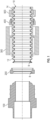
- FIG. 1 is an exploded, cross-sectional view of a fitting and flexible piping in an example embodiment.
- the piping 10 includes flexible, annular-corrugated, metal tubing 12 (e.g., copper alloy, stainless steel, etc.) and a jacket 14 having a smooth exterior.
- the jacket 14 may be a coextruded, nonmetallic jacket which fills the spaces between the corrugations (e.g., peaks and valleys), thereby mechanically attaching the jacket 14 to the corrugated metal tubing 12.
- the jacket 14 is a polymeric jacket such as low-density polyethylene. Other materials that offer sufficient tensile strength to resist corrugation movement under pressure could be utilized.
- Jacket 14 may include one or more fire retardant additives.
- the jacket 14 may meet ASTM E84, with maximum Flame Spread index of 25 and maximum Smoke Density Index of 50.
- the piping 10 may be implemented using MEDITRAC ® metal piping for medical applications.
- the fitting includes an adaptor 100, sealing member 200, nut 300, jacket lock ring 400 and swage sleeve 500. Each of these elements is described herein, along with the assembly of the fitting as depicted in FIG. 9 .
- the sealing member 200 is made of metal
- the adaptor 100, nut 300, jacket lock ring 400 and swage sleeve 500 may be made from metal (e.g., brass or stainless steel).
- FIG. 2 is a cross-sectional view of the adaptor 100.
- a first end of the adaptor 100 includes a cylindrical recess 102 for receiving a metal (e.g., copper) pipe.
- the metal pipe may be brazed to adaptor 100.
- Recess 102 may have various inner diameters to accommodate different sizes of metal pipe.
- a flow conduit 104 is formed in adaptor 100 centered about a centerline of the adaptor 100.
- a guiding diameter 108 is provided at termination end 106 of the adaptor 100.
- the guiding diameter 108 is a cylindrical lip that is slightly smaller than the inner diameter of the metal tubing 12 (at a valley). The guiding diameter 108 facilitates centering the metal tubing 12 with the adaptor 100 to promote a better seal between the adaptor 100 and the metal tubing 12.
- An adaptor sealing surface 110 is located adjacent to the guiding diameter 108. As described in further detail herein, the adaptor sealing surface 110 interacts with a sealing surface on sealing member 200 to compress the metal tubing 12 and form a metal-to-metal seal.
- the adaptor sealing surface 110 is curved or arcuate.
- adaptor sealing surface 110 is a section of a sphere or toroid.
- the sealing surface on sealing member 200 may be linear, planar or frusto-conical. The interaction between the curved adaptor sealing surface 110 and the planar sealing surface on sealing member 200 creates a line seal, thereby reducing the axial compression load required to create a seal when installing the fitting.
- the adapter centering surface 112 Adjacent to the adaptor sealing surface 110 is an adaptor centering surface 112.
- the adapter centering surface 112 has an outer diameter slightly smaller than an inner diameter of a first cavity 306 ( FIG. 3 ) of the nut 300 to center the nut 300 on the adaptor 100.
- a front edge of the adapter centering surface 112 may be chamfered to facilitate insertion of the adaptor 100 into the nut 300.
- the adapter centering surface 112 adjoins a sealing ridge 114.
- the sealing ridge 114 has an outer diameter greater than the outer diameter of the adapter centering surface 112.
- the sealing ridge 114 has an outer diameter greater than the inner diameter of the first cavity 306 of the nut 300.
- the sealing ridge 114 may be curved and comprise a section of a sphere or toroid. As the outer diameter of the sealing ridge 114 has an outer diameter greater than the inner diameter of cavity 306 of the nut 300, the adaptor 100 is press fit into the nut 300 and creates a fluid impermeable seal between the adaptor 100 and nut 300.
- An engagement surface 116 is located rearward of the sealing ridge 114.
- the engagement surface 116 has an outer diameter slightly smaller than a major diameter of the sealing ridge 114 and slightly larger than outer diameter of the adapter centering surface 112.
- the engagement surface 116 has an outer diameter slightly larger than the inner diameter of cavity 306 of the nut 300.
- the engagement surface 116 helps to center the adaptor 100 to the nut 300 as the adaptor 100 is press fit into the nut 300 and creates a snug fit between the adaptor 100 and nut 300.
- a locking ridge 118 is located rearward of the engagement surface 116.
- the locking ridge 118 is slightly larger in major diameter than major diameter of sealing ridge 114 and larger than the inner diameter of cavity 306 of nut 300.
- the locking ridge 118 may be triangular is cross section, providing an edge that mechanically fixes the nut 300 on adaptor 100.
- FIG. 3 is a cross-sectional view of the nut 300 of FIG. 1 .
- a flow conduit 304 is formed in nut 300 centered about a centerline of the nut 300.
- Nut 300 receives adaptor 100 in a first cavity 306 and receives the piping 10 through a second cavity 308.
- the first cavity 306 has a beveled opening 310 to facilitate insertion of the adaptor 100 into the first cavity 306.
- a shoulder 312 extends radially inwardly between the first cavity 306 and the second cavity 308 and serves as stop to limit travel of the sealing member 200.
- FIG. 4 is a cross-sectional view of the sealing member 200 of FIG. 1 .
- the sealing member may be implemented using a pair of split rings, a collet, a c-ring, etc.
- the sealing member 200 is a split ring.
- a forward end of the sealing member 200 (the end facing the adaptor 100) includes a sealing surface 202.
- the sealing surface is linear in cross-section and may be frusto-conical.
- the sealing surface 202 is 55 degrees relative to the central axis of the adaptor 100. It is understood that the sealing surface 202 may have different shapes.
- the rear end of the sealing member 200 (the end facing the piping 10) includes a cavity 204 having an arcuate shape to receive a peak of the metal tubing 12.
- a circumferential flange 206 extends rearward and defines a circumferential notch 208 on a periphery of the sealing member 200.
- the flange 206 has an outer diameter less than the inner diameter of shoulder 312 of the nut 300. Shoulder 312 is received in notch 208 when the fitting is assembled to limit travel of the sealing member 200, and therefore limit travel of piping 10.
- the sealing member 200 includes a radially inward facing, circumferential lip 212.
- the inner diameter of the lip 212 is sized to be slightly larger than the outer diameter of a valley on the metal tubing 12.
- the lip 212 is received in a valley on the metal tubing 12 to position the sealing member 200 on the piping 10.
- FIG. 5 is an end view of a jacket lock ring 400 of FIG. 1 .
- the jacket lock ring 400 in FIG. 5 is a C-ring that is compressed by the swage sleeve 500 to mechanically engage jacket 14 of piping 10.
- the jacket lock ring 400 has a thickness x at a front end (facing the adaptor 100).
- the thickness of the jacket lock ring 400 tapers to a thickness, y, by virtue of ramp 402.
- x is 0.15 inches and y is 0.007 inches.
- the inside surface of the jacket lock ring 400 includes one or more ridges 404 shaped to engage jacket 14 of piping 10.
- the ridges 404 may be radially arranged on an interior surface of the jacket lock ring 400.
- the ridges in FIG. 7 have triangular cross-section providing an edge to engage the jacket 14. It is understood that other cross-sections may be used for the ridge(s) 404.
- the outer diameter of the jacket lock ring 400 is slightly less than the inner diameter of second cavity 308 in nut 300.
- FIG. 8 is a cross-sectional view of the swage sleeve 500 of FIG. 1 .
- the swage sleeve 500 is generally cylindrical.
- a front edge (facing the adaptor 100) is angled (e.g., 20 degrees with respect to the centerline of the fitting) to define a tapered surface 502.
- the tapered surface 502 coacts with the ramp 402 on the jacket lock ring 400 to compress the jacket lock ring 400 inwards towards the centerline of the fitting. This drives the ridges 402 into jacket 14 to mechanically secure the fitting to the piping 10.
- the outer diameter of the swage sleeve 500 is slightly less than the inner diameter of second cavity 308 in nut 300 so that the swage sleeve 500 is press fit into the nut 300 to mechanically secure the swage sleeve 50 to the nut 300.
- FIG. 9 is a cross-sectional view of the fitting and piping 10 assembled in an example embodiment.
- the jacket 14 is removed to expose at least two full peaks and at least a portion of a valley past the second peak.
- the piping is cut at the distal end in a valley of the metal tubing 12.
- the piping 10 is fed through the swage sleeve 500, jacket lock ring 400 and nut 300.
- the sealing device 200 is affixed to the exposed metal tubing 12 such that the sealing surface 202 is placed directly behind the first peak of the metal tubing 12, with lip 220 in a valley of the metal tubing 12.
- the piping 10 can then be pulled back until the sealing device 200 contacts shoulder 312 on nut 300.
- the, jacket lock ring 400 and swage sleeve 500 can be positioned in second cavity 308 of nut 300, to the extent possible by hand.
- the adaptor 100 is positioned into first cavity 306 of nut 300, to the extent possible by hand.
- a compression tool is used to simultaneously drive the adaptor 100 into nut 300 and drive the swage sleeve 500 into nut 300.
- Driving the adaptor 100 into first cavity 306 causes several actions to occur.
- a seal is formed between the adaptor sealing surface 110, the metal tubing 12 and the sealing surface 202.
- This seal is a primary seal, and comprises a double flare of metal tubing 12 compressed between the adaptor sealing surface 110 and the sealing surface 202.
- a line seal is formed on the metal tubing 12.
- the sealing ridge 114 engages the inner diameter of cavity 306 of the nut 300, to create a fluid impermeable seal between the adaptor 100 and nut 300.
- the locking ridge 118 engages the inner surface of cavity 306 of nut 300, to mechanically fix the nut 300 to adaptor 100.
- the swage sleeve 500 is driven into the second cavity 308 of the nut 300.
- the tapered surface 502 coacts with the ramp 402 on the jacket lock ring 400 to compress the jacket lock ring 400 inwards towards the centerline of the fitting. This drives the ridges 402 into jacket 14 to mechanically secure the fitting to the piping 10, preventing any expansion under pressure.
- the interference between the outer diameter of the swage sleeve 500 and the inner diameter of the cavity 308 secures the swage sleeve 500 to the nut 300.
- the piping may be installed in lengths far longer than that available with rigid, copper piping. This greatly reduces installation time by eliminating the need to set up and breakdown sealed, vented installation areas. Further, using a press-fit connection eliminates the need for brazing the fitting to the piping.
Landscapes
- Engineering & Computer Science (AREA)
- General Engineering & Computer Science (AREA)
- Mechanical Engineering (AREA)
- Health & Medical Sciences (AREA)
- Heart & Thoracic Surgery (AREA)
- Animal Behavior & Ethology (AREA)
- Public Health (AREA)
- Biomedical Technology (AREA)
- Hematology (AREA)
- Life Sciences & Earth Sciences (AREA)
- Pulmonology (AREA)
- General Health & Medical Sciences (AREA)
- Anesthesiology (AREA)
- Veterinary Medicine (AREA)
- Joints With Pressure Members (AREA)
- Infusion, Injection, And Reservoir Apparatuses (AREA)
- Gasket Seals (AREA)
- Quick-Acting Or Multi-Walled Pipe Joints (AREA)
- Memory System Of A Hierarchy Structure (AREA)
- Pipe Accessories (AREA)
Claims (14)
- Anschlussstück zur Verwendung mit einem metallischen, gewellten Rohr (12), das Spitzen und Täler aufweist, wobei das Anschlussstück Folgendes umfasst:eine Mutter (300), die so konfiguriert ist, dass sie das Rohr (12) aufnimmt;ein Dichtungselement (200), das aus Metall hergestellt ist, zur Platzierung in einem Tal des Rohrs (12), wobei das Dichtungselement (200) eine Dichtungsfläche (202) einschließt, undeinen Adapter (100), der zum Einpressen in die Mutter (300) konfiguriert ist, wobei der Adapter (100) eine Adapterdichtungsfläche (110) einschließt;Wobei bei der Montage der Adapter (100) in die Mutter (300) eingepresst wird und das Rohr (12) zwischen der Adapterdichtungsfläche (110) und der Dichtungsfläche (202) zusammengedrückt und aufgeweitet wird.
- Anschlussstück nach Anspruch 1, wobei die Adapterdichtungsfläche (110) bogenförmig ist.
- Anschlussstück nach Anspruch 2, wobei die Adapterdichtungsfläche (110) kugelförmig oder toroidal ist.
- Anschlussstück nach Anspruch 2, wobei die Dichtungsfläche (202) flach ist.
- Anschlussstück nach Anspruch 2, wobei die Dichtungsfläche (202) frusto-konisch ist.
- Anschlussstück nach Anspruch 1, wobei die Mutter (300) einen ersten Hohlraum (306) einschließt, der zur Aufnahme des Adapters (100) konfiguriert ist;
wobei der Adapter (100) einen darauf ausgebildeten Dichtungssteg (114) einschließt, wobei der Dichtungssteg (114) einen Außendurchmesser aufweist, der größer ist als ein Innendurchmesser des ersten Hohlraums (306). - Anschlussstück nach Anspruch 1, wobei die Mutter (300) einen ersten Hohlraum (306) einschließt, der zur Aufnahme des Adapters (100) konfiguriert ist;
wobei der Adapter (100) einen darauf ausgebildeten Verriegelungssteg (118) einschließt, wobei der Verriegelungssteg (118) einen Außendurchmesser aufweist, der größer ist als ein Innendurchmesser des ersten Hohlraums (306). - Anschlussstück nach Anspruch 7, wobei der Verriegelungssteg (118) eine Kante einschließt, die die Mutter (300) mechanisch an dem Adapter (100) fixiert.
- Anschlussstück nach Anspruch 6, wobei:
der Adapter einen Verriegelungssteg (118) einschließt, der daran ausgebildet und von dem Dichtungssteg (114) beabstandet ist, wobei der Verriegelungssteg (118) einen Außendurchmesser aufweist, der größer ist als der Außendurchmesser des Dichtungsstegs (114). - Anschlussstück nach Anspruch 9, wobei der Verriegelungssteg (118) eine Kante einschließt, die die Mutter (300) mechanisch an dem Adapter (100) fixiert.
- Anschlussstück nach Anspruch 9, wobei der Adapter (100) eine Eingriffsfläche (116) einschließt, die sich zwischen dem Dichtungssteg (114) und dem Verriegelungssteg (118) befindet, wobei die Eingriffsfläche (116) einen Außendurchmesser aufweist, der größer ist als der Innendurchmesser des ersten Hohlraums (306).
- Anschlussstück nach Anspruch 1 zur Verwendung mit einem Rohr (12), das von einem Mantel (14) umschlossen ist, wobei:die Mutter (300) einen zweiten Hohlraum (308) einschließt, unddas Anschlussstück ferner Folgendes umfasst:einen Mantelverriegelungsring (400), der zur Platzierung in dem zweiten Hohlraum (308) konfiguriert ist, wobei der Mantelverriegelungsring (400) eine Außenfläche, die eine sich verjüngende Rampe (402) einschließt, und eine Innenfläche, die mindestens einen Steg (404) einschließt, der so konfiguriert ist, dass er mit dem Mantel (14) in Eingriff kommt, einschließt,eine Quetschhülse (500), die für die Platzierung in dem zweiten Hohlraum (308) konfiguriert ist, wobei die Quetschhülse (500) eine sich verjüngende Fläche (502) einschließt, die in Richtung der Rampe (402) an dem Mantelverriegelungsring (400) weist.
- Anschlussstück nach Anspruch 12, wobei:
bei der Montage die Quetschhülse (500) in den zweiten Hohlraum (308) eingepresst wird und die verjüngte Fläche (502) der Quetschhülse (500) in die Rampe (402) des Mantelverriegelungsrings (400) eingreift, um den Mantelverriegelungsring (400) in Richtung des Mantels (14) zu drücken. - Anschlussstück nach Anspruch 1 zur Verwendung mit einem Rohr (12), das von einem Mantel (14) umschlossen ist, wobei:die Mutter (300) einen ersten Hohlraum (306) und einen zweiten Hohlraum (308) und eine Schulter (312) einschließt, die sich zwischen dem ersten Hohlraum (306) und dem zweiten Hohlraum (308) radial nach innen erstreckt, und so konfiguriert ist, dass sie das Rohr (12) durch den zweiten Hohlraum (308) aufnimmt;das Dichtungselement (200) eine umlaufende Kerbe (208) einschließt, wobei die Kerbe (208) so konfiguriert ist, dass sie an der Schulter (312) anliegt und diese aufnimmt, um die Bewegung des Dichtungselements (200) zu begrenzen;wobei der Adapter (100) einen darauf ausgebildeten Dichtungssteg (114) einschließt, wobei der Dichtungssteg (114) einen Außendurchmesser aufweist, der größer ist als ein Innendurchmesser des ersten Hohlraums (306);das Anschlussstück ferner einschließt:einen Mantelverriegelungsring (400), der zur Platzierung in dem zweiten Hohlraum (308) konfiguriert ist, wobei der Mantelverriegelungsring (400) eine Außenfläche, die eine sich verjüngende Rampe (402) einschließt, und eine Innenfläche, die mindestens einen Steg (404) einschließt, der so konfiguriert ist, dass er mit dem Mantel (14) in Eingriff kommt, einschließt,eine Quetschhülse (500), die für die Platzierung in dem zweiten Hohlraum (308) konfiguriert ist, wobei die Quetschhülse (500) eine sich verjüngende Fläche (502) einschließt, die in Richtung der Rampe (402) an dem Mantelverriegelungsring (400) weist;wobei bei der Montage der Adapter (100) in den ersten Hohlraum (306) eingepresst wird und die Quetschhülse (500) in den zweiten Hohlraum (308) eingepresst wird und die verjüngte Fläche (502) der Quetschhülse (500) in die Rampe (402) des Mantelverriegelungsrings (400) eingreift, um den Mantelverriegelungsring (400) in Richtung des Mantels (14) zu drücken.
Priority Applications (3)
| Application Number | Priority Date | Filing Date | Title |
|---|---|---|---|
| RS20230460A RS64284B1 (sr) | 2017-01-27 | 2018-01-18 | Spojnica za medicinski cevovodni sistem |
| HRP20230589TT HRP20230589T1 (hr) | 2017-01-27 | 2018-01-18 | Spojnica za medicinski cjevovodni sistem |
| SI201830935T SI3574243T1 (sl) | 2017-01-27 | 2018-01-18 | Fiting za medicinski sistem cevi |
Applications Claiming Priority (2)
| Application Number | Priority Date | Filing Date | Title |
|---|---|---|---|
| US15/417,440 US10539257B2 (en) | 2017-01-27 | 2017-01-27 | Fitting for medical piping system |
| PCT/US2018/014160 WO2018140274A1 (en) | 2017-01-27 | 2018-01-18 | Fitting for medical piping system |
Publications (3)
| Publication Number | Publication Date |
|---|---|
| EP3574243A1 EP3574243A1 (de) | 2019-12-04 |
| EP3574243A4 EP3574243A4 (de) | 2020-12-16 |
| EP3574243B1 true EP3574243B1 (de) | 2023-03-22 |
Family
ID=62977644
Family Applications (1)
| Application Number | Title | Priority Date | Filing Date |
|---|---|---|---|
| EP18744783.4A Active EP3574243B1 (de) | 2017-01-27 | 2018-01-18 | Anschlussstück für ein medizinisches leitungssystem |
Country Status (27)
| Country | Link |
|---|---|
| US (1) | US10539257B2 (de) |
| EP (1) | EP3574243B1 (de) |
| CN (1) | CN110337557B (de) |
| AR (1) | AR110781A1 (de) |
| AU (1) | AU2018213958B2 (de) |
| CA (1) | CA3051688A1 (de) |
| CL (1) | CL2019002085A1 (de) |
| CO (1) | CO2019008108A2 (de) |
| DK (1) | DK3574243T3 (de) |
| ES (1) | ES2947982T3 (de) |
| FI (1) | FI3574243T3 (de) |
| HR (1) | HRP20230589T1 (de) |
| HU (1) | HUE062014T2 (de) |
| IL (1) | IL268073B2 (de) |
| LT (1) | LT3574243T (de) |
| MX (1) | MX2019008932A (de) |
| PE (1) | PE20191396A1 (de) |
| PL (1) | PL3574243T3 (de) |
| PT (1) | PT3574243T (de) |
| RS (1) | RS64284B1 (de) |
| RU (1) | RU2761694C2 (de) |
| SA (1) | SA519402286B1 (de) |
| SI (1) | SI3574243T1 (de) |
| TW (1) | TWI755473B (de) |
| UY (1) | UY37583A (de) |
| WO (1) | WO2018140274A1 (de) |
| ZA (1) | ZA201905196B (de) |
Families Citing this family (3)
| Publication number | Priority date | Publication date | Assignee | Title |
|---|---|---|---|---|
| ES3002763T3 (en) | 2018-01-19 | 2025-03-07 | Omega Flex Inc | Corrugated medical tubing system having fitting with anti-tamper sleeve |
| CN109968722B (zh) * | 2019-03-14 | 2020-11-06 | 杭州富阳新堰纸制品有限公司 | 一种波纹塑料管收紧装置 |
| CN120267910A (zh) * | 2025-05-27 | 2025-07-08 | 眉山市人民医院 | 一种t管引流装置 |
Family Cites Families (32)
| Publication number | Priority date | Publication date | Assignee | Title |
|---|---|---|---|---|
| US3528689A (en) * | 1967-12-22 | 1970-09-15 | Homer D Roe | Tube joint |
| DE2132190A1 (de) * | 1971-06-29 | 1973-01-18 | Zako Rohrverbindungen Gmbh & C | Verfahren und vorrichtung zum doppelboerdeln von rohren |
| US4251094A (en) * | 1979-05-10 | 1981-02-17 | Noll Manufacturing Co. | Spirally wound corrugated pipe connector |
| DE3701555C1 (de) * | 1987-01-21 | 1988-07-07 | Mannesmann Ag | Rohrverbindung fuer duennwandige,kleinkalibrige Metallrohre |
| US5088771A (en) * | 1990-02-06 | 1992-02-18 | Sierracin Corporation | Tube union |
| DE4105782A1 (de) * | 1991-02-23 | 1992-09-03 | Siegfried Fuehrmann | Verfahren zum befestigen einer anschlussarmatur am ende eines ring- oder schraubenfoermig gewellten metallrohres |
| DE4108741A1 (de) * | 1991-03-18 | 1992-09-24 | Bundy Gmbh | Rohrverbindung |
| US5921591A (en) | 1992-10-07 | 1999-07-13 | Argent; Michael E. | Pipe connecting assembly and method for joining two lengths of pipe by a press-fit connection |
| US5799989A (en) | 1996-08-08 | 1998-09-01 | Omega-Flex, Inc. | Corrugated tubing fitting |
| US20020117226A1 (en) | 2001-02-28 | 2002-08-29 | Malcarne John A. | Reinforced corrugated tubing system |
| DE10322972B4 (de) * | 2003-05-21 | 2013-12-24 | Continental Automotive Gmbh | Verbindungselement |
| WO2005124217A1 (en) | 2004-06-18 | 2005-12-29 | Dong-A Flexible Metal Tubes Co., Ltd | Connector of flexible pipe |
| DK1769184T3 (da) * | 2004-06-25 | 2012-05-07 | Omega Flex Inc | Genanvendeligt forbindelsesstykke til rørsystem |
| CN2842130Y (zh) * | 2005-11-01 | 2006-11-29 | 航天晨光股份有限公司 | 非焊接结构金属管 |
| US7621567B2 (en) | 2006-05-24 | 2009-11-24 | Titeflex Corporation | Corrugated tube fitting with a ridge sealing device and method |
| BRPI0717029A2 (pt) * | 2006-08-31 | 2013-10-01 | Titeflex Corp | conexço de dobra para tubos corrugados de aÇo inoxidÁvel |
| CN201028199Y (zh) * | 2007-03-14 | 2008-02-27 | 吴文庆 | 改进型燃气用波纹管快速接头 |
| CN101684874A (zh) * | 2008-09-25 | 2010-03-31 | 何永水 | 中央空调水系统末端连接管及其制作工艺 |
| CN101649937B (zh) * | 2009-09-08 | 2011-04-20 | 林仁国 | 一种燃气用波纹管快速接头 |
| US8925976B2 (en) * | 2010-03-02 | 2015-01-06 | Omega Flex, Inc. | Flanged fitting for use with tubing containment system |
| KR101182371B1 (ko) * | 2010-04-05 | 2012-09-12 | 동아금속주름관(주) | 주름관 연결구조 |
| EP2764286A1 (de) * | 2011-10-07 | 2014-08-13 | Titeflex Corporation | Buchsen, dichtungsanordnungen, rohrleitungen und verfahren zur installation von rohrleitungen |
| US9140392B2 (en) * | 2013-04-11 | 2015-09-22 | Omega Flex, Inc. | Fitting for tubing containment system |
| PT3155693T (pt) * | 2014-06-16 | 2021-03-11 | Omega Flex Inc | Encaixe para uso com cabo blindado |
| EP3926223A1 (de) * | 2014-11-03 | 2021-12-22 | Omega Flex, Inc. | Armatur, verfahren zur verbindung eines wellrohrs mit einer armatur und verwendung einer armatur |
| US10024469B2 (en) * | 2014-11-04 | 2018-07-17 | Titeflex Corporation | Sealing devices, bushing, and systems including the same |
| CN204420379U (zh) * | 2014-11-04 | 2015-06-24 | 浙江盾运实业有限公司 | 波纹管接头 |
| CN204533919U (zh) * | 2015-01-21 | 2015-08-05 | 宁波索立管业有限公司 | 一种波纹管自密封式机械压紧套筒 |
| US10281071B2 (en) * | 2015-12-02 | 2019-05-07 | Titeflex Corporation | Bushings and fittings, tubing assemblies, and methods incorporating the same |
| CN205824411U (zh) * | 2016-06-30 | 2016-12-21 | 林仁国 | 一种燃气用波纹管的快速接头 |
| US10598304B2 (en) * | 2017-01-03 | 2020-03-24 | Titeflex Corporation | Energy-dissipative tubes, arc-trapping bushings, and kits, systems, and methods incorporating the same |
| US10865919B2 (en) * | 2017-02-06 | 2020-12-15 | Ward Manufacturing LLC | Termination for sheathed tubing with leak containment and detection provisions |
-
2017
- 2017-01-27 US US15/417,440 patent/US10539257B2/en active Active
-
2018
- 2018-01-18 SI SI201830935T patent/SI3574243T1/sl unknown
- 2018-01-18 EP EP18744783.4A patent/EP3574243B1/de active Active
- 2018-01-18 RU RU2019122605A patent/RU2761694C2/ru active
- 2018-01-18 WO PCT/US2018/014160 patent/WO2018140274A1/en not_active Ceased
- 2018-01-18 FI FIEP18744783.4T patent/FI3574243T3/fi active
- 2018-01-18 PL PL18744783.4T patent/PL3574243T3/pl unknown
- 2018-01-18 RS RS20230460A patent/RS64284B1/sr unknown
- 2018-01-18 PE PE2019001493A patent/PE20191396A1/es unknown
- 2018-01-18 CN CN201880008829.2A patent/CN110337557B/zh active Active
- 2018-01-18 HU HUE18744783A patent/HUE062014T2/hu unknown
- 2018-01-18 CA CA3051688A patent/CA3051688A1/en active Pending
- 2018-01-18 ES ES18744783T patent/ES2947982T3/es active Active
- 2018-01-18 HR HRP20230589TT patent/HRP20230589T1/hr unknown
- 2018-01-18 MX MX2019008932A patent/MX2019008932A/es unknown
- 2018-01-18 LT LTEPPCT/US2018/014160T patent/LT3574243T/lt unknown
- 2018-01-18 IL IL268073A patent/IL268073B2/en unknown
- 2018-01-18 PT PT187447834T patent/PT3574243T/pt unknown
- 2018-01-18 AU AU2018213958A patent/AU2018213958B2/en active Active
- 2018-01-18 DK DK18744783.4T patent/DK3574243T3/da active
- 2018-01-24 TW TW107102578A patent/TWI755473B/zh active
- 2018-01-26 UY UY0001037583A patent/UY37583A/es active IP Right Grant
- 2018-01-26 AR ARP180100186A patent/AR110781A1/es active IP Right Grant
-
2019
- 2019-07-24 SA SA519402286A patent/SA519402286B1/ar unknown
- 2019-07-25 CL CL2019002085A patent/CL2019002085A1/es unknown
- 2019-07-26 CO CONC2019/0008108A patent/CO2019008108A2/es unknown
- 2019-08-06 ZA ZA2019/05196A patent/ZA201905196B/en unknown
Also Published As
Similar Documents
| Publication | Publication Date | Title |
|---|---|---|
| CN103201551B (zh) | 具有套管的推动连接管接头 | |
| US4932689A (en) | Hose fitting assembly | |
| US20120200081A1 (en) | Connector apparatus | |
| EP2627936B1 (de) | Wellrohranschluss | |
| EP3574243B1 (de) | Anschlussstück für ein medizinisches leitungssystem | |
| US20110204624A1 (en) | Universal connection socket | |
| US20230243450A1 (en) | Plumbing fitting | |
| CN102918313B (zh) | 用于与管道封闭系统使用的法兰式接头 | |
| US12296136B2 (en) | Corrugated medical tubing system having fitting with anti-tamper sleeve | |
| JP2018017293A (ja) | 耐圧型管継手及び耐圧型管継手構造 | |
| EP4279788B1 (de) | Steckverbindung | |
| HK40009407A (en) | Fitting for medical piping system | |
| US20230003322A1 (en) | Tubular connector | |
| HK40009407B (zh) | 用於医用管道系统的配件 | |
| BR112019015221B1 (pt) | Conector para sistema de tubulação médica | |
| HK1180385B (en) | Flanged fitting for use with tubing containment system |
Legal Events
| Date | Code | Title | Description |
|---|---|---|---|
| STAA | Information on the status of an ep patent application or granted ep patent |
Free format text: STATUS: THE INTERNATIONAL PUBLICATION HAS BEEN MADE |
|
| PUAI | Public reference made under article 153(3) epc to a published international application that has entered the european phase |
Free format text: ORIGINAL CODE: 0009012 |
|
| STAA | Information on the status of an ep patent application or granted ep patent |
Free format text: STATUS: REQUEST FOR EXAMINATION WAS MADE |
|
| 17P | Request for examination filed |
Effective date: 20190813 |
|
| AK | Designated contracting states |
Kind code of ref document: A1 Designated state(s): AL AT BE BG CH CY CZ DE DK EE ES FI FR GB GR HR HU IE IS IT LI LT LU LV MC MK MT NL NO PL PT RO RS SE SI SK SM TR |
|
| AX | Request for extension of the european patent |
Extension state: BA ME |
|
| DAV | Request for validation of the european patent (deleted) | ||
| DAX | Request for extension of the european patent (deleted) | ||
| A4 | Supplementary search report drawn up and despatched |
Effective date: 20201117 |
|
| RIC1 | Information provided on ipc code assigned before grant |
Ipc: F16L 19/00 20060101AFI20201111BHEP Ipc: F16L 37/08 20060101ALI20201111BHEP Ipc: F16B 23/00 20060101ALI20201111BHEP Ipc: F16L 33/26 20060101ALI20201111BHEP Ipc: F16L 19/04 20060101ALI20201111BHEP |
|
| GRAP | Despatch of communication of intention to grant a patent |
Free format text: ORIGINAL CODE: EPIDOSNIGR1 |
|
| STAA | Information on the status of an ep patent application or granted ep patent |
Free format text: STATUS: GRANT OF PATENT IS INTENDED |
|
| INTG | Intention to grant announced |
Effective date: 20221026 |
|
| GRAS | Grant fee paid |
Free format text: ORIGINAL CODE: EPIDOSNIGR3 |
|
| GRAA | (expected) grant |
Free format text: ORIGINAL CODE: 0009210 |
|
| STAA | Information on the status of an ep patent application or granted ep patent |
Free format text: STATUS: THE PATENT HAS BEEN GRANTED |
|
| AK | Designated contracting states |
Kind code of ref document: B1 Designated state(s): AL AT BE BG CH CY CZ DE DK EE ES FI FR GB GR HR HU IE IS IT LI LT LU LV MC MK MT NL NO PL PT RO RS SE SI SK SM TR |
|
| REG | Reference to a national code |
Ref country code: GB Ref legal event code: FG4D |
|
| REG | Reference to a national code |
Ref country code: CH Ref legal event code: EP |
|
| REG | Reference to a national code |
Ref country code: DE Ref legal event code: R096 Ref document number: 602018047483 Country of ref document: DE |
|
| REG | Reference to a national code |
Ref country code: IE Ref legal event code: FG4D |
|
| REG | Reference to a national code |
Ref country code: AT Ref legal event code: REF Ref document number: 1555493 Country of ref document: AT Kind code of ref document: T Effective date: 20230415 |
|
| REG | Reference to a national code |
Ref country code: FI Ref legal event code: FGE |
|
| REG | Reference to a national code |
Ref country code: PT Ref legal event code: SC4A Ref document number: 3574243 Country of ref document: PT Date of ref document: 20230622 Kind code of ref document: T Free format text: AVAILABILITY OF NATIONAL TRANSLATION Effective date: 20230619 |
|
| REG | Reference to a national code |
Ref country code: DK Ref legal event code: T3 Effective date: 20230621 |
|
| REG | Reference to a national code |
Ref country code: NL Ref legal event code: FP |
|
| REG | Reference to a national code |
Ref country code: GR Ref legal event code: EP Ref document number: 20230400872 Country of ref document: GR Effective date: 20230710 |
|
| REG | Reference to a national code |
Ref country code: SK Ref legal event code: T3 Ref document number: E 41698 Country of ref document: SK |
|
| REG | Reference to a national code |
Ref country code: NO Ref legal event code: T2 Effective date: 20230322 |
|
| REG | Reference to a national code |
Ref country code: EE Ref legal event code: FG4A Ref document number: E023399 Country of ref document: EE Effective date: 20230614 |
|
| P01 | Opt-out of the competence of the unified patent court (upc) registered |
Effective date: 20230717 |
|
| REG | Reference to a national code |
Ref country code: ES Ref legal event code: FG2A Ref document number: 2947982 Country of ref document: ES Kind code of ref document: T3 Effective date: 20230825 |
|
| PG25 | Lapsed in a contracting state [announced via postgrant information from national office to epo] |
Ref country code: SE Free format text: LAPSE BECAUSE OF FAILURE TO SUBMIT A TRANSLATION OF THE DESCRIPTION OR TO PAY THE FEE WITHIN THE PRESCRIBED TIME-LIMIT Effective date: 20230322 |
|
| REG | Reference to a national code |
Ref country code: HR Ref legal event code: T1PR Ref document number: P20230589 Country of ref document: HR |
|
| REG | Reference to a national code |
Ref country code: HU Ref legal event code: AG4A Ref document number: E062014 Country of ref document: HU |
|
| PG25 | Lapsed in a contracting state [announced via postgrant information from national office to epo] |
Ref country code: SM Free format text: LAPSE BECAUSE OF FAILURE TO SUBMIT A TRANSLATION OF THE DESCRIPTION OR TO PAY THE FEE WITHIN THE PRESCRIBED TIME-LIMIT Effective date: 20230322 |
|
| REG | Reference to a national code |
Ref country code: DE Ref legal event code: R097 Ref document number: 602018047483 Country of ref document: DE |
|
| REG | Reference to a national code |
Ref country code: HR Ref legal event code: ODRP Ref document number: P20230589 Country of ref document: HR Payment date: 20231121 Year of fee payment: 7 |
|
| PLBE | No opposition filed within time limit |
Free format text: ORIGINAL CODE: 0009261 |
|
| STAA | Information on the status of an ep patent application or granted ep patent |
Free format text: STATUS: NO OPPOSITION FILED WITHIN TIME LIMIT |
|
| 26N | No opposition filed |
Effective date: 20240102 |
|
| PG25 | Lapsed in a contracting state [announced via postgrant information from national office to epo] |
Ref country code: MC Free format text: LAPSE BECAUSE OF FAILURE TO SUBMIT A TRANSLATION OF THE DESCRIPTION OR TO PAY THE FEE WITHIN THE PRESCRIBED TIME-LIMIT Effective date: 20230322 |
|
| PG25 | Lapsed in a contracting state [announced via postgrant information from national office to epo] |
Ref country code: MC Free format text: LAPSE BECAUSE OF FAILURE TO SUBMIT A TRANSLATION OF THE DESCRIPTION OR TO PAY THE FEE WITHIN THE PRESCRIBED TIME-LIMIT Effective date: 20230322 |
|
| PG25 | Lapsed in a contracting state [announced via postgrant information from national office to epo] |
Ref country code: BG Free format text: LAPSE BECAUSE OF FAILURE TO SUBMIT A TRANSLATION OF THE DESCRIPTION OR TO PAY THE FEE WITHIN THE PRESCRIBED TIME-LIMIT Effective date: 20230322 |
|
| PG25 | Lapsed in a contracting state [announced via postgrant information from national office to epo] |
Ref country code: BG Free format text: LAPSE BECAUSE OF FAILURE TO SUBMIT A TRANSLATION OF THE DESCRIPTION OR TO PAY THE FEE WITHIN THE PRESCRIBED TIME-LIMIT Effective date: 20230322 |
|
| REG | Reference to a national code |
Ref country code: HR Ref legal event code: ODRP Ref document number: P20230589 Country of ref document: HR Payment date: 20241224 Year of fee payment: 8 |
|
| REG | Reference to a national code |
Ref country code: AT Ref legal event code: UEP Ref document number: 1555493 Country of ref document: AT Kind code of ref document: T Effective date: 20230322 |
|
| PGFP | Annual fee paid to national office [announced via postgrant information from national office to epo] |
Ref country code: LT Payment date: 20251218 Year of fee payment: 9 Ref country code: GB Payment date: 20251204 Year of fee payment: 9 |
|
| PGFP | Annual fee paid to national office [announced via postgrant information from national office to epo] |
Ref country code: FI Payment date: 20251230 Year of fee payment: 9 |
|
| PGFP | Annual fee paid to national office [announced via postgrant information from national office to epo] |
Ref country code: HR Payment date: 20251208 Year of fee payment: 9 Ref country code: FR Payment date: 20251208 Year of fee payment: 9 Ref country code: NL Payment date: 20251215 Year of fee payment: 9 |
|
| PGFP | Annual fee paid to national office [announced via postgrant information from national office to epo] |
Ref country code: GR Payment date: 20251210 Year of fee payment: 9 |
|
| PGFP | Annual fee paid to national office [announced via postgrant information from national office to epo] |
Ref country code: IE Payment date: 20251209 Year of fee payment: 9 |
|
| PGFP | Annual fee paid to national office [announced via postgrant information from national office to epo] |
Ref country code: LV Payment date: 20251219 Year of fee payment: 9 |
|
| PGFP | Annual fee paid to national office [announced via postgrant information from national office to epo] |
Ref country code: PL Payment date: 20251212 Year of fee payment: 9 |
|
| PGFP | Annual fee paid to national office [announced via postgrant information from national office to epo] |
Ref country code: EE Payment date: 20251229 Year of fee payment: 9 |
|
| PGFP | Annual fee paid to national office [announced via postgrant information from national office to epo] |
Ref country code: SK Payment date: 20251212 Year of fee payment: 9 Ref country code: RO Payment date: 20251223 Year of fee payment: 9 |
|
| PGFP | Annual fee paid to national office [announced via postgrant information from national office to epo] |
Ref country code: RS Payment date: 20251219 Year of fee payment: 9 |
|
| PGFP | Annual fee paid to national office [announced via postgrant information from national office to epo] |
Ref country code: SI Payment date: 20251215 Year of fee payment: 9 |
|
| REG | Reference to a national code |
Ref country code: HR Ref legal event code: ODRP Ref document number: P20230589 Country of ref document: HR Payment date: 20251208 Year of fee payment: 9 |
|
| REG | Reference to a national code |
Ref country code: CH Ref legal event code: U11 Free format text: ST27 STATUS EVENT CODE: U-0-0-U10-U11 (AS PROVIDED BY THE NATIONAL OFFICE) Effective date: 20260201 |
|
| PGFP | Annual fee paid to national office [announced via postgrant information from national office to epo] |
Ref country code: LU Payment date: 20260116 Year of fee payment: 9 |
|
| PGFP | Annual fee paid to national office [announced via postgrant information from national office to epo] |
Ref country code: HU Payment date: 20260112 Year of fee payment: 9 |
|
| PGFP | Annual fee paid to national office [announced via postgrant information from national office to epo] |
Ref country code: ES Payment date: 20260213 Year of fee payment: 9 |
|
| PGFP | Annual fee paid to national office [announced via postgrant information from national office to epo] |
Ref country code: NO Payment date: 20260109 Year of fee payment: 9 Ref country code: DK Payment date: 20260113 Year of fee payment: 9 Ref country code: DE Payment date: 20251210 Year of fee payment: 9 |
|
| PGFP | Annual fee paid to national office [announced via postgrant information from national office to epo] |
Ref country code: AT Payment date: 20251230 Year of fee payment: 9 |
|
| PGFP | Annual fee paid to national office [announced via postgrant information from national office to epo] |
Ref country code: BE Payment date: 20260106 Year of fee payment: 9 Ref country code: IT Payment date: 20251219 Year of fee payment: 9 |
|
| PGFP | Annual fee paid to national office [announced via postgrant information from national office to epo] |
Ref country code: IS Payment date: 20260113 Year of fee payment: 9 |
|
| PGFP | Annual fee paid to national office [announced via postgrant information from national office to epo] |
Ref country code: TR Payment date: 20260114 Year of fee payment: 9 |
|
| PGFP | Annual fee paid to national office [announced via postgrant information from national office to epo] |
Ref country code: PT Payment date: 20260119 Year of fee payment: 9 Ref country code: CZ Payment date: 20260109 Year of fee payment: 9 Ref country code: CH Payment date: 20260201 Year of fee payment: 9 |
|
| PGFP | Annual fee paid to national office [announced via postgrant information from national office to epo] |
Ref country code: CY Payment date: 20251209 Year of fee payment: 9 |