EP3574205B1 - Steuerventilanordnung und verfahren zur herstellung davon - Google Patents
Steuerventilanordnung und verfahren zur herstellung davon Download PDFInfo
- Publication number
- EP3574205B1 EP3574205B1 EP18702476.5A EP18702476A EP3574205B1 EP 3574205 B1 EP3574205 B1 EP 3574205B1 EP 18702476 A EP18702476 A EP 18702476A EP 3574205 B1 EP3574205 B1 EP 3574205B1
- Authority
- EP
- European Patent Office
- Prior art keywords
- face
- valve
- spool
- sleeve
- bore
- Prior art date
- Legal status (The legal status is an assumption and is not a legal conclusion. Google has not performed a legal analysis and makes no representation as to the accuracy of the status listed.)
- Active
Links
Images
Classifications
-
- F—MECHANICAL ENGINEERING; LIGHTING; HEATING; WEAPONS; BLASTING
- F02—COMBUSTION ENGINES; HOT-GAS OR COMBUSTION-PRODUCT ENGINE PLANTS
- F02M—SUPPLYING COMBUSTION ENGINES IN GENERAL WITH COMBUSTIBLE MIXTURES OR CONSTITUENTS THEREOF
- F02M63/00—Other fuel-injection apparatus having pertinent characteristics not provided for in groups F02M39/00 - F02M57/00 or F02M67/00; Details, component parts, or accessories of fuel-injection apparatus, not provided for in, or of interest apart from, the apparatus of groups F02M39/00 - F02M61/00 or F02M67/00; Combination of fuel pump with other devices, e.g. lubricating oil pump
- F02M63/0012—Valves
- F02M63/0031—Valves characterized by the type of valves, e.g. special valve member details, valve seat details, valve housing details
- F02M63/004—Sliding valves, e.g. spool valves, i.e. whereby the closing member has a sliding movement along a seat for opening and closing
-
- F—MECHANICAL ENGINEERING; LIGHTING; HEATING; WEAPONS; BLASTING
- F02—COMBUSTION ENGINES; HOT-GAS OR COMBUSTION-PRODUCT ENGINE PLANTS
- F02M—SUPPLYING COMBUSTION ENGINES IN GENERAL WITH COMBUSTIBLE MIXTURES OR CONSTITUENTS THEREOF
- F02M63/00—Other fuel-injection apparatus having pertinent characteristics not provided for in groups F02M39/00 - F02M57/00 or F02M67/00; Details, component parts, or accessories of fuel-injection apparatus, not provided for in, or of interest apart from, the apparatus of groups F02M39/00 - F02M61/00 or F02M67/00; Combination of fuel pump with other devices, e.g. lubricating oil pump
- F02M63/0012—Valves
- F02M63/0059—Arrangements of valve actuators
- F02M63/0064—Two or more actuators acting on two or more valve bodies
-
- B—PERFORMING OPERATIONS; TRANSPORTING
- B23—MACHINE TOOLS; METAL-WORKING NOT OTHERWISE PROVIDED FOR
- B23P—METAL-WORKING NOT OTHERWISE PROVIDED FOR; COMBINED OPERATIONS; UNIVERSAL MACHINE TOOLS
- B23P15/00—Making specific metal objects by operations not covered by a single other subclass or a group in this subclass
- B23P15/001—Making specific metal objects by operations not covered by a single other subclass or a group in this subclass valves or valve housings
-
- F—MECHANICAL ENGINEERING; LIGHTING; HEATING; WEAPONS; BLASTING
- F02—COMBUSTION ENGINES; HOT-GAS OR COMBUSTION-PRODUCT ENGINE PLANTS
- F02M—SUPPLYING COMBUSTION ENGINES IN GENERAL WITH COMBUSTIBLE MIXTURES OR CONSTITUENTS THEREOF
- F02M47/00—Fuel-injection apparatus operated cyclically with fuel-injection valves actuated by fluid pressure
- F02M47/02—Fuel-injection apparatus operated cyclically with fuel-injection valves actuated by fluid pressure of accumulator-injector type, i.e. having fuel pressure of accumulator tending to open, and fuel pressure in other chamber tending to close, injection valves and having means for periodically releasing that closing pressure
- F02M47/027—Electrically actuated valves draining the chamber to release the closing pressure
-
- F—MECHANICAL ENGINEERING; LIGHTING; HEATING; WEAPONS; BLASTING
- F02—COMBUSTION ENGINES; HOT-GAS OR COMBUSTION-PRODUCT ENGINE PLANTS
- F02M—SUPPLYING COMBUSTION ENGINES IN GENERAL WITH COMBUSTIBLE MIXTURES OR CONSTITUENTS THEREOF
- F02M51/00—Fuel-injection apparatus characterised by being operated electrically
- F02M51/06—Injectors peculiar thereto with means directly operating the valve needle
- F02M51/061—Injectors peculiar thereto with means directly operating the valve needle using electromagnetic operating means
- F02M51/0625—Injectors peculiar thereto with means directly operating the valve needle using electromagnetic operating means characterised by arrangement of mobile armatures
-
- F—MECHANICAL ENGINEERING; LIGHTING; HEATING; WEAPONS; BLASTING
- F02—COMBUSTION ENGINES; HOT-GAS OR COMBUSTION-PRODUCT ENGINE PLANTS
- F02M—SUPPLYING COMBUSTION ENGINES IN GENERAL WITH COMBUSTIBLE MIXTURES OR CONSTITUENTS THEREOF
- F02M63/00—Other fuel-injection apparatus having pertinent characteristics not provided for in groups F02M39/00 - F02M57/00 or F02M67/00; Details, component parts, or accessories of fuel-injection apparatus, not provided for in, or of interest apart from, the apparatus of groups F02M39/00 - F02M61/00 or F02M67/00; Combination of fuel pump with other devices, e.g. lubricating oil pump
- F02M63/0012—Valves
- F02M63/0031—Valves characterized by the type of valves, e.g. special valve member details, valve seat details, valve housing details
- F02M63/0033—Lift valves, i.e. having a valve member that moves perpendicularly to the plane of the valve seat
- F02M63/0035—Poppet valves, i.e. having a mushroom-shaped valve member that moves perpendicularly to the plane of the valve seat
-
- F—MECHANICAL ENGINEERING; LIGHTING; HEATING; WEAPONS; BLASTING
- F02—COMBUSTION ENGINES; HOT-GAS OR COMBUSTION-PRODUCT ENGINE PLANTS
- F02M—SUPPLYING COMBUSTION ENGINES IN GENERAL WITH COMBUSTIBLE MIXTURES OR CONSTITUENTS THEREOF
- F02M2200/00—Details of fuel-injection apparatus, not otherwise provided for
- F02M2200/46—Valves, e.g. injectors, with concentric valve bodies
-
- F—MECHANICAL ENGINEERING; LIGHTING; HEATING; WEAPONS; BLASTING
- F02—COMBUSTION ENGINES; HOT-GAS OR COMBUSTION-PRODUCT ENGINE PLANTS
- F02M—SUPPLYING COMBUSTION ENGINES IN GENERAL WITH COMBUSTIBLE MIXTURES OR CONSTITUENTS THEREOF
- F02M2200/00—Details of fuel-injection apparatus, not otherwise provided for
- F02M2200/80—Fuel injection apparatus manufacture, repair or assembly
- F02M2200/8061—Fuel injection apparatus manufacture, repair or assembly involving press-fit, i.e. interference or friction fit
-
- F—MECHANICAL ENGINEERING; LIGHTING; HEATING; WEAPONS; BLASTING
- F02—COMBUSTION ENGINES; HOT-GAS OR COMBUSTION-PRODUCT ENGINE PLANTS
- F02M—SUPPLYING COMBUSTION ENGINES IN GENERAL WITH COMBUSTIBLE MIXTURES OR CONSTITUENTS THEREOF
- F02M2200/00—Details of fuel-injection apparatus, not otherwise provided for
- F02M2200/80—Fuel injection apparatus manufacture, repair or assembly
- F02M2200/8069—Fuel injection apparatus manufacture, repair or assembly involving removal of material from the fuel apparatus, e.g. by punching, hydro-erosion or mechanical operation
-
- F—MECHANICAL ENGINEERING; LIGHTING; HEATING; WEAPONS; BLASTING
- F02—COMBUSTION ENGINES; HOT-GAS OR COMBUSTION-PRODUCT ENGINE PLANTS
- F02M—SUPPLYING COMBUSTION ENGINES IN GENERAL WITH COMBUSTIBLE MIXTURES OR CONSTITUENTS THEREOF
- F02M2200/00—Details of fuel-injection apparatus, not otherwise provided for
- F02M2200/80—Fuel injection apparatus manufacture, repair or assembly
- F02M2200/8092—Fuel injection apparatus manufacture, repair or assembly adjusting or calibration
Definitions
- the present invention relates to a control valve assembly of a fuel injector and to the manufacturing of a precision valve lift.
- Fuel injectors comprise a control valve assembly for varying the pressure in a control chamber and commanding the moves of a needle valve member enabling or preventing injection events.
- a valve spool slides within a bore of a valve body to alternatively open and close a spill orifice.
- the maximum valve lift which is to be adjusted within a dimensional tolerance of few micrometers, is set by taking measurements of the spool head height and, adjusting the valve lift to the desired value by adding shim of appropriate thickness.
- Another effective way of achieving an accurate lift is to use selective assembly methods wherein the components are manufactured and sorted in families prior to be paired with other components to form valve assemblies. Although being efficient, such a process is not desired for the valve arrangement and production environment, the problem being to ensure that the correct distribution of parts is manufactured to cover the variability of the combinations of components. A large selection of parts may remain unused or, issues may arise where the right distribution of parts is not available to achieve the correct combination.
- Some injectors are designed with two valve arrangements, each comprising a spool sliding in a bore between closed and open positions.
- the problem of having the correct valve lift for both is amplified with such control valve assemblies. Due to process variability it is unlikely that all valve heads will be the same, so to achieve equal lifts is a major problem however the challenge remains the same where different lifts are required for each valve.
- US2005098144A1 discloses a fuel injector with a homogenous charge nozzle outlet set and a conventional nozzle outlet set that are controlled respectively by first and second three-way needle control valves.
- Each fuel injector includes first and second concentric needle valve members. One of the needle valve members moves to an open position for a homogenous charge injection event, while the other needle valve member moves to an open position for a conventional injection event.
- the fuel injector has the ability to operate in a homogenous charge mode with a homogenous charge spray pattern, a conventional mode with a conventional spray pattern or a mixed mode.
- EP 1 612 398 A1 shows a control servo valve housed inside the casing of an internal combustion engine fuel injector, the outlet passage comes out inside an annular chamber defined by a fixed tubular portion and by a shutter, which engages the tubular portion in substantially fluid tight manner.
- valve assembly comprising a first valve arrangement wherein a first valve spool is guided in a first hydraulic bore provided in a body (18) of the assembly, said spool being adapted to move between a closed position wherein a shoulder face of a head member of said first spool is in sealing contact against a first seating face and, a fully open position wherein a distant end face of said head member is in flush continuity with an under face of the body of the valve assembly, the shoulder face of the first spool being lifted away from said first seating face.
- control valve assembly further comprises a first tubular sleeve having a seating portion which end face defines said first seating face, the first sleeve being fixed in the first hydraulic bore and the first spool extending through said sleeve.
- the first sleeve further comprises a spool guiding portion integral to the press-fitted seating portion, said guiding portion being arranged inside the hydraulic bore.
- said spool guiding portion has an inner guiding face against which, in use, slides the spool and, externally an outer face distant from the bore by an outer annular clearance.
- the seating portion is press-fitted in the bore and, it has an inner face defining an inner clearance with the spool.
- the control valve further comprises a second valve arrangement, similar to the first valve arrangement, wherein a second spool is guided in a second hydraulic bore provided in the body of the assembly, said second spool being adapted to move between a closed position wherein a shoulder face of a head member of said second spool is in sealing contact against a second seating face and, a fully open position wherein a distant end face of said second head member is in flush continuity with an under face of the body of the valve assembly, the shoulder face of the second spool being lifted from said second seating face.
- a second valve arrangement similar to the first valve arrangement, wherein a second spool is guided in a second hydraulic bore provided in the body of the assembly, said second spool being adapted to move between a closed position wherein a shoulder face of a head member of said second spool is in sealing contact against a second seating face and, a fully open position wherein a distant end face of said second head member is in flush continuity with an under face of the body of the valve assembly, the shoulder face
- the control valve assembly further comprises a second tubular sleeve having a second seating portion defining said second seating face, said second sleeve being fixed in the second hydraulic bore, the second spool extending through said second sleeve.
- the second sleeve has an outer face press fitted in the second bore (34) and, an inner face defining a second clearance with the second spool.
- the body of the valve assembly comprises a valve guide member provided with the hydraulic bore and, a valve plate having an upper face and an opposed under face, the upper face being arranged in surface abutment against an under face of the valve guide member, said valve plate being further provided with a through opening aligned with the hydraulic bore, the sleeve being fixed in the valve guide member so that the seating face lies parallel and in close vicinity to the under face of the valve guide member, either slightly recessed inside the hydraulic bore or slightly protruding in the opening.
- the second hydraulic bore is defined in the valve guide member and, the valve plate is provided with a second through opening aligned with the second hydraulic bore, the second sleeve being press fitted in the valve guide member so that the second seating face lies parallel and in close vicinity to the under face of the valve guide member, either slightly recessed inside the second hydraulic bore or slightly protruding in the second opening.
- the invention further extends to a fuel injector comprising a control valve assembly as previously described.
- the invention further extends to a method of manufacturing a control valve assembly as previously described, the method particularly enabling to ensure a precised valve lift measured between the closed position and the fully open position of the valve arrangement, the method comprising the steps of:
- the providing step is:
- the method further comprises the step:
- the adjusting step comprises:
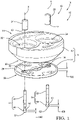
- a fuel injector 10 To inject fuel in a cylinder of an internal combustion engine, a fuel injector 10 is provided with a control valve assembly 12 arranged between an actuator member and a nozzle assembly, all said parts being firmly maintained together by a capnut.
- the control valve assembly 12 enables to vary the pressure in a control chamber such that, a needle valve sliding in the nozzle moves to open or to close spray holes and thus enables or forbids injection events.
- control valve assembly 12 shown on figure 1 is taken from a diesel fuel injector 10 and, it comprises a first 14 and a second 16 valve arrangement cooperating together for enabling pressurised fuel to enter the control chamber and then, for preventing said entry when the fuel therein is expelled toward a low pressure tank.
- the first 14 and second 16 valve arrangements are similar, each comprising a hydraulic bore 32, 34 defining a seating face 40, 42 cooperating with a shoulder face 50, 60 defined on a valve spool 44, 54 slidably arranged in the bore.
- the spool comprises a thin and elongated core 46, 56 enlarging at an end to form a larger valve head 48, 58 defining said seat face.
- control valve assembly 12 has a body 18 comprising a valve guide member 20, a valve plate 22, a first sleeve 24 and a second sleeve 26.
- the valve plate 22 is arranged beneath the guide member 20, the upper face 28 of the plate 22 being in surface contact against the under face 30 of the guide member 20, said valve plate 22 having a thickness T22 measured between said upper face 28 and an opposed under face 29.
- valve body 18 may be monobloc, integrating in one piece the valve guide 20 and the valve plate 22, the under face 29 being in such alternative the under face of the body 18.
- the first valve arrangement 14 comprises a first hydraulic bore 32 and, the second valve arrangement 16 comprises a second hydraulic bore 34, both bores 32, 34 being parallel to each other and extending along a main axis X to which the under face 30 of the valve guide and the upper face 28 of the valve plate are perpendicular.
- the two bores 32, 34 are provided in the guide member 20 and are both opening in said under face 30.
- the valve plate 22 is complementary provided with a first opening 36 aligned with the first bore 32 and, with a second opening 38 aligned with the second bore 34.
- each of the bores 32, 34 open in large recesses forming chambers adapted to house magnetic armatures, not shown, cooperating with a solenoid of the actuator member.
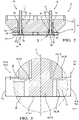
- the first sleeve 24 is inserted with press-fit in the first bore 32 and similarly, the second sleeve 26 is inserted with press-fit in the second bore 34, each of the first 24 and the second 26 sleeve being a cylindrical tubular member arranged so their lower end face, respectively defining a first valve seating face 40 and a second valve seating face 42, is flush with the under face 30 of the guide member.
- the actual first distance D40 from said first valve seating face 40 to the under face 30 and, the actual second distance D42 from said second valve seating face 42 to the under face 30 are within a range of few micrometers, said distances D40, D42 being counted positive when the sleeve is slightly recessed inside the bore and negative when the sleeve protrudes outside.
- the first valve arrangement 14 further comprises a first valve spool 44 guided in the first bore 32 and similarly, the second valve arrangement 16 further comprises with a second valve spool 54 guided in the second bore 34.
- the first valve spool 44 has a thin and elongated core 46 enlarging at an end into a larger head member 48, a shoulder face 50 joining the core 46 to the head member 48 and defining said first seat face.
- the core 46 is guided in the first bore 32 and it extends through the first sleeve 24 while the head member 48 protrudes outside of the first bore 32 and of the sleeve 24, inside the first opening 36 of the valve plate.
- the head member 48 has a height H48 axially X extending from said shoulder face 50 to a distant transverse end face 52, said height H48 being smaller than the thickness T22 of the valve plate 22.
- the first spool 44 Opposite to the head 48, the first spool 44 upwardly extends in the large recess and a first magnetic armature, not shown, is fixed to said part of the spool.
- the injector 10 is assembled so, an upper face of the nozzle assembly is pressed in surface contact against the under face 29 of the valve plate closing, at least partially, the first and second openings 36, 38 of the valve plate.
- the shoulder face 50 of the first spool 44 cooperates with the first seating face 40 of the first sleeve as said first spool 44 axially slides between an open position OP and a closed position CP.
- open position OP the shoulder face 50 is lifted away from the first seating face 40 and the end face 52 of the head abuts said upper face of the nozzle so, said end face 52 lies in exact flush continuity with the under face 29 of the valve plate.
- closed position CP the shoulder face 50 is in sealing contact against the first valve seating face 40 and, the end face 52 of the head is recessed inside the first opening 36 away from the upper face of the nozzle.
- the second valve spool 54 has an elongated thin core 56 enlarging at an end into a larger head member 58, a shoulder face 60 joining the core 56 to the head member 58 and defining said second seat face.
- the core 56 is guided in the second bore 34 and it extends through the second sleeve 26 while the head member 58 protrudes outside of the second bore 34 and of the second sleeve 26, inside the second opening 38 of the valve plate.
- the head member 58 has a height H58 axially X extending from said shoulder face 60 to a distant transverse end face 62, said height H58 being smaller than the thickness T22 of the valve plate 22.
- the second spool 54 Opposite to the head 58, the second spool 54 upwardly extends in the large recess and a second magnetic armature, not shown, is fixed to said part of the spool.
- the operation of the second valve arrangement 16 requires the shoulder face 60 of the second spool 54 and the second seating face 42 of the second sleeve to cooperate together as said second spool 54 axially slides in the body 18 between an open position OP and a closed position CP.
- said open position OP the shoulder face 60 is lifted away from the second seating face 42 and the end face 62 of the head abuts the upper face of the nozzle so, said end face 62 lies in exact flush continuity with the under face 29 of the valve plate.
- closed position CP the shoulder face 60 is in sealing contact against the second valve seating face 42 and the end face 62 of the head is recessed inside the second opening 38 away from the upper face of the nozzle.
- said distances D40, D42 are counted positive when the sleeve is slightly recessed inside the bore because increasing the available lift distance and, being counted negative when the sleeve protrudes outside the bore thus decreasing the available distance.
- the respective height H48, H58 of the first 48 and second 58 head members differ within a dimensional tolerance of few microns.
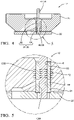
- the first sleeve 24 integrally comprises a seating portion 64 and a guiding portion 66, the seating portion 64, drawn at the bottom of the figure, defining the seating face 40 and, the guiding portion 66, drawn above, entirely lying inside the first hydraulic bore 32.
- Said first sleeve 24 defines an inner clearance C64 between the first spool 44 and the inner face 68 of said seating portion 64 and, an outer annular clearance C66 between the outer face of the guiding portion 66 and the first bore 32.
- the first spool 44 being axially guided by the inner face 70 of the guiding portion 66. Thanks to this sleeve arrangement, dilation of the stem bore 70 is prevented since equal pressure is acting on both sides of the sleeve guiding portion 66, then dilation of the bore is minimised as the net radial force is balanced.
- the lift of the spool is individually tuned in following the steps of a method 100, which in a first stage is detailed considering a control valve assembly 12 having an integral mono-bloc body and a single valve arrangement.
- the steps of said method 100 are as follow:
- the method 100 further comprises: 124) surfacing together the valve guide under face 30 and the sleeve 24 so that the bottom end of said sleeve defining the seating face 40 is exactly flush in surface continuity with the valve guide under face 30.
- Said surfacing 124 can for instance be a grinding operation.
- the thickness T22 of the valve plate corresponds to the depth of the larger recess in which opens the bore.
- the spool is chosen so the height H48 of its ahead is smaller than the thickness T22 of the plate or the depth of the recess.
- Said fine positioning step 144 may consist in pushing the sleeves outwardly so it protrudes by said distance D40, D42 outside the bore or, in pushing inwardly should the seating face be recessed relative the guide under face. It could finally consist not moving a sleeve at all, should the initial position be correct.
- the lifts L44, L54 being independently tuned, may be selected to differ from each other, one sleeve being pushed inwardly while the other is pushed outwardly.
- a control valve assembly provided with more than two valve arrangements can similarly benefit for the invention by having, in each valve arrangement a sleeve which position is individually adjusted.
Landscapes
- Engineering & Computer Science (AREA)
- Mechanical Engineering (AREA)
- Chemical & Material Sciences (AREA)
- Combustion & Propulsion (AREA)
- General Engineering & Computer Science (AREA)
- Physics & Mathematics (AREA)
- Fluid Mechanics (AREA)
- Electromagnetism (AREA)
- Fuel-Injection Apparatus (AREA)
Claims (18)
- Steuerventilbaugruppe (12) einer Kraftstoffeinspritzdüse (10), wobei die Ventilbaugruppe eine erste Ventilanordnung (14) umfasst, wobei ein erster Ventilschieber (44) in einer ersten hydraulischen Bohrung (32) geführt ist, die in einem Körper (18) der Baugruppe bereitgestellt ist, wobei der Schieber (44) angepasst ist, um sich zwischen einer geschlossenen Position (closed position - CP), wobei eine Schulterfläche (50) eines Kopfelements (48) des ersten Schiebers in abdichtender Berührung gegen eine erste Auflagefläche (40) steht, und einer vollständig geöffneten Position (open position - OP) zu bewegen, wobei eine entfernte Endfläche (52) des Kopfelements in bündiger Kontinuität mit einer unteren Fläche (29) des Körpers der Ventilbaugruppe steht, wobei die Schulterfläche (50) des ersten Schiebers von der ersten Auflagefläche (40) abgehoben wird,
dadurch gekennzeichnet, dass
die Steuerventilbaugruppe (12) ferner eine erste röhrenförmige Hülse (24) umfasst, die einen Auflageabschnitt (64) aufweist, dessen Endfläche die erste Auflagefläche (40) definiert, wobei die erste Hülse in der ersten hydraulischen Bohrung (32) befestigt ist und sich der erste Schieber durch die Hülse (24) erstreckt. - Steuerventilbaugruppe (12) nach dem vorhergehenden Anspruch, wobei die erste Hülse (24) ferner einen Schieberführungsabschnitt (66) einstückig mit dem pressgepassten Auflageabschnitt (64) umfasst, wobei der Führungsabschnitt (66) in der hydraulischen Bohrung (32) angeordnet ist.
- Steuerventilbaugruppe (12) nach Anspruch 2, wobei der Schieberführungsabschnitt (66) eine innere Führungsfläche (70), gegen die der Schieber (44), in Verwendung, gleitet, und außen eine äußere Fläche aufweist, die von der Bohrung (32) durch einen äußeren Ringspalt (C66) entfernt ist.
- Steuerventilbaugruppe (12) nach einem der vorhergehenden Ansprüche, wobei der Auflageabschnitt (64) in die Bohrung (32) pressgepasst ist und eine innere Fläche (68) aufweist, die einen inneren Spalt (C64) mit dem Schieber (44) definiert.
- Steuerventilbaugruppe (12) nach einem der vorhergehenden Ansprüche, ferner umfassend eine zweite Ventilanordnung (16), ähnlich der ersten Ventilanordnung (14), wobei ein zweiter Schieber (54) in einer zweiten hydraulischen Bohrung (34) geführt ist, die in dem Körper (18) der Baugruppe bereitgestellt ist, wobei der zweite Schieber (54) angepasst ist, um sich zwischen einer geschlossenen Position (CP), wobei eine Schulterfläche (60) eines Kopfelements (58) des zweiten Schiebers (54) in abdichtender Berührung gegen eine zweite Auflagefläche (42) steht, und einer vollständig geöffneten Position (OP) zu bewegen, wobei eine entfernte Endfläche (62) des zweiten Kopfelements (58) in bündiger Kontinuität mit einer unteren Fläche (30) des Körpers der Ventilbaugruppe steht, wobei die Schulterfläche (60) des zweiten Schiebers von der zweiten Auflagefläche (42) angehoben wird, und wobei die Steuerventilbaugruppe (12) ferner eine zweite röhrenförmige Hülse (26) umfasst, die einen zweiten Auflageabschnitt (64) aufweist, der die zweite Auflagefläche (42) definiert, wobei die zweite Hülse (26) in der zweiten hydraulischen Bohrung (34) befestigt ist, wobei sich der zweite Schieber (54) durch die zweite Hülse erstreckt.
- Steuerventilbaugruppe (12) nach Anspruch 5, wobei die zweite Hülse (26) eine äußere Fläche, die in die zweite Bohrung (34) pressgepasst ist, und eine innere Fläche aufweist, die einen zweiten Spalt mit dem zweiten Schieber (54) definiert.
- Steuerventilbaugruppe (12) nach einem der vorhergehenden Ansprüche, wobei der Körper (18) der Ventilbaugruppe ein Ventilführungselement (20), das mit der hydraulischen Bohrung (32) versehen ist, und eine Ventilplatte (22) umfasst, die eine obere Fläche (28) und eine gegenüberliegende untere Fläche (29) aufweist, wobei die obere Fläche (28) in Oberflächenanlage gegen eine untere Fläche (30) des Ventilführungselements angeordnet ist, wobei die Ventilplatte (22) ferner mit einer Durchgangsöffnung (36) versehen ist, die mit der hydraulischen Bohrung (32, 34) ausgerichtet ist, wobei die Hülse (24) in dem Ventilführungselement (20) befestigt ist, so dass die Auflagefläche (40) parallel und in unmittelbarer Nähe zu der unteren Fläche (30) des Ventilführungselements liegt, entweder leicht vertieft in der hydraulischen Bohrung oder leicht in die Öffnung vorstehend.
- Steuerventilbaugruppe (12) nach Anspruch 7, wobei die zweite hydraulische Bohrung (34) in dem Ventilführungselement (20) definiert ist und die Ventilplatte (22) mit einer zweiten Durchgangsöffnung (38) versehen ist, die mit der zweiten hydraulischen Bohrung (34) ausgerichtet ist, wobei die zweite Hülse (26) in das Ventilführungselement (20) pressgepasst ist, so dass die zweite Auflagefläche (42) parallel und in unmittelbarer Nähe zu der unteren Fläche (30) des Ventilführungselements liegt, entweder leicht vertieft in der zweiten hydraulischen Bohrung (34) oder leicht in die zweite Öffnung vorstehend.
- Steuerventilbaugruppe (12) nach einem der Ansprüche 7 oder 8, wobei der erste Schieber (44) zwischen der geschlossenen Position (CP) und der vollständig geöffneten Position (OP) einen maximalen Hub (L44) aufweist, der gemäß der Formel berechnet wird:
 T22 die Dicke der Ventilplatte (22) ist,D40 der Versatzabstand von der ersten Auflagefläche (40) zu der Ventilführungsunterfläche (30) ist und,H48 die Höhe des Kopfes (48) des ersten Schiebers ist.
 - Steuerventilbaugruppe (12) nach einem der Ansprüche 7 bis 9, wobei zwischen der geschlossenen Position (CP) und der vollständig geöffneten Position (OP), der zweite Schieber (54) einen maximalen Hub (L54) aufweist, der gemäß der Formel berechnet wird:
 T22 die Dicke der Ventilplatte (22) ist,D42 der Abstand von der ersten Auflagefläche (42) zu der Ventilführungsunterfläche (30) ist und,H58 die Höhe des Kopfes (58) des zweiten Schiebers ist.
 - Kraftstoffeinspritzdüse (10), umfassend eine Steuerventilbaugruppe (12) nach einem der vorhergehenden Ansprüche.
- Verfahren (100) zum Herstellen einer Steuerventilbaugruppe (12) nach einem der vorhergehenden Ansprüche, wobei das Verfahren insbesondere ermöglicht, einen präzisen Ventilhub (L44), gemessen zwischen der geschlossenen Position (CP) und der vollständig geöffneten Position (OP) der Ventilanordnung, sicherzustellen, das Verfahren (100) umfassend die folgenden Schritte:110) Bereitstellen eines Ventilkörpers (18), der eine hydraulische Bohrung (32) definiert;112) Bereitstellen eines Ventilschiebers (44), der ein Kopfelement (48) aufweist, das einen Kern (46) über eine Schulterfläche (50) verbindet;114) Bereitstellen einer Hülse (24), die angepasst ist, um in die Bohrung (32) eingesetzt zu werden, wobei die Hülse (24) eine Ventilauflagefläche (40) definiert;120) Ineingriffnehmen und Einsetzen der Hülse (24) mit Presspassung in die Bohrung (32), so dass die Auflagefläche (40) in unmittelbarer Nähe zu der unteren Fläche (30) des Ventilkörpers steht;130) Anordnen des Ventilschiebers (44), so dass sich der Kern (46) in der Hülse (24) erstreckt und das Kopfelement (48) außerhalb der Hülse liegt, wobei die Schulterfläche (50) in der Lage ist, mit der Ventilauflagefläche (40) zusammenzuwirken;140) Einstellen der Position der Hülse (24) auf den gewünschten maximalen Hub (L44) des Schiebers.
- Verfahren (100) nach Anspruch 12, wobei die Steuerventilbaugruppe (12) mit einer zweiten Ventilanordnung (16) nach einem der Ansprüche 7 oder 8 versehen ist, wobei die Schritte des Verfahrens sind:110) Bereitstellen eines Ventilkörpers (18), der eine erste (32) und eine zweite (34) hydraulische Bohrung definiert;112) Bereitstellen eines ersten Ventilschiebers (44), der ein Kopfelement (48) aufweist, das einen Kern (46) über eine Schulterfläche (50) verbindet, und eines zweiten Schiebers (54), der ein Kopfelement (58) aufweist, das einen Kern (56) über eine Schulterfläche (60) verbindet;114) Bereitstellen einer ersten Hülse (24), die angepasst ist, um in die erste Bohrung (32) eingesetzt zu werden, und angepasst ist, um den Kern (46) des ersten Schiebers gleitend aufzunehmen, wobei die erste Hülse (24) eine erste Ventilauflagefläche (40) definiert und
eine zweite Hülse (26), die angepasst ist, um in die zweite Bohrung (34) eingesetzt zu werden, und angepasst ist, um den Kern (56) des zweiten Schiebers gleitend aufzunehmen, wobei die zweite Hülse (26) eine zweite Ventilauflagefläche (42) definiert;120) Ineingriffnehmen und Einsetzen, mit Presspassung, der ersten Hülse (24) in die erste Bohrung (32) und der zweiten Hülse (26) in die zweite Bohrung (34);130) Gleitendes Ineingriffnehmendes Kerns (46) des ersten Schiebers in der ersten Hülse (24), wobei das erste Kopfelement (48) aus der ersten Hülse herausragt und,des Kerns (56) des zweiten Schiebers in der zweiten Hülse (26), wobei das zweite Kopfelement (58) aus der zweiten Hülse herausragt;140) Einstellen der axialen Position der ersten Hülse (24) in der ersten Bohrung (32) auf den gewünschten ersten maximalen Hub (L44) des ersten Schiebers (44) und Einstellen der axialen Position der zweiten Hülse (26) in der zweiten Bohrung (34) auf den gewünschten zweiten maximalen Hub (L54) des zweiten Schiebers. - Verfahren nach Anspruch 13, wobei der Steuerventilkörper mit einem Ventilführungselement (20) und einer Ventilplatte (22) versehen ist, der Bereitstellungsschritt 110 ist:
110) Bereitstellen des Ventilführungselements (20), das mit zwei hydraulischen Bohrungen (32, 34) versehen ist, und einer Ventilplatte (22), die mit zwei Öffnungen (36, 38) versehen ist, die komplementär zu den Bohrungen (32, 34) ausgerichtet sind. - Verfahren nach Anspruch 14, ferner umfassend die Schritte:111) Messen der Dicke (T22) der Ventilplatte, wobei diese Messung nach dem Bereitstellen (110) der Ventilplatte durchgeführt wird.113) Messen der Höhe (H48, H58) jedes der Schieberköpfe (48, 58), wobei diese Messung nach dem Bereitstellungsschritt (112) durchgeführt wird.
- Verfahren (100) nach einem der Ansprüche 14 oder 15, ferner umfassend den Schritt:
124) Auflegen der Ventilführungsunterfläche (30) und der zwei Hülsen (24, 26), so dass die unteren Enden der Hülsen, die jeweils die Auflageflächen (40, 42) definieren, in Oberflächenkontinuität genau bündig mit der Ventilführungsunterseite (30) sind. - Verfahren (100) nach Anspruch 16, wobei der Auflegevorgang (124) ein Schleifvorgang ist.
- Verfahren (100) nach einem der Ansprüche 14 bis 17, wobei der Einstellschritt (140) umfasst:142) Auswählen des maximal möglichen Hubs (L44, L54) für jeden des ersten (44) und des zweiten (54) Schiebers;144) Feinpositionieren jeder Hülse (24, 26), um die Ventilauflagefläche (40, 42) von der Führungselementunterfläche (30) um einen Abstand zu versetzen:


D40 und D42 der axiale Versatzabstand von der Ventilführungselementunterfläche (30) zu der ersten (40) beziehungsweise der zweiten (42) Auflagefläche sind, H48 und H58 die Kopfhöhe des ersten und deszweiten Schiebers sind und, T22 die Dicke der Ventilplatte ist.
Applications Claiming Priority (2)
| Application Number | Priority Date | Filing Date | Title |
|---|---|---|---|
| GB1701454.9A GB2559174B (en) | 2017-01-30 | 2017-01-30 | Control valve assembly and method of manufacturing thereof |
| PCT/EP2018/052176 WO2018138365A1 (en) | 2017-01-30 | 2018-01-29 | Control valve assembly and method of manufacturing thereof |
Publications (2)
| Publication Number | Publication Date |
|---|---|
| EP3574205A1 EP3574205A1 (de) | 2019-12-04 |
| EP3574205B1 true EP3574205B1 (de) | 2022-08-10 |
Family
ID=58462816
Family Applications (1)
| Application Number | Title | Priority Date | Filing Date |
|---|---|---|---|
| EP18702476.5A Active EP3574205B1 (de) | 2017-01-30 | 2018-01-29 | Steuerventilanordnung und verfahren zur herstellung davon |
Country Status (4)
| Country | Link |
|---|---|
| US (1) | US11506164B2 (de) |
| EP (1) | EP3574205B1 (de) |
| GB (1) | GB2559174B (de) |
| WO (1) | WO2018138365A1 (de) |
Citations (2)
| Publication number | Priority date | Publication date | Assignee | Title |
|---|---|---|---|---|
| US20050098144A1 (en) * | 2002-09-25 | 2005-05-12 | Stewart Chris L. | Mixed mode fuel injector and injection system |
| EP2620632A1 (de) * | 2012-01-26 | 2013-07-31 | Delphi Technologies Holding S.à.r.l. | Steuerventil |
Family Cites Families (12)
| Publication number | Priority date | Publication date | Assignee | Title |
|---|---|---|---|---|
| US4421280A (en) * | 1981-09-28 | 1983-12-20 | The Bendix Corporation | Fuel injector |
| US4978074A (en) * | 1989-06-21 | 1990-12-18 | General Motors Corporation | Solenoid actuated valve assembly |
| US6761325B2 (en) * | 1998-09-16 | 2004-07-13 | Westport Research Inc. | Dual fuel injection valve and method of operating a dual fuel injection valve |
| US6260776B1 (en) * | 2000-01-12 | 2001-07-17 | Woodward Governor Company | Universal gaseous fuel injector cartridge |
| FR2853317B1 (fr) | 2003-04-01 | 2006-07-07 | Atofina | Alcoxyamines issues de nitroxydes b-phosphores, leur utilisation pour la preparation de mono-ou polyalcoxyamines, polymerisees ou non |
| US20040227018A1 (en) * | 2003-05-15 | 2004-11-18 | Robert Bosch Fuel Systems Corporation | Modular fuel injector for an internal combustion engine |
| EP1612398B1 (de) * | 2004-06-30 | 2006-10-04 | C.R.F. Società Consortile per Azioni | Kraftstoffinjektor mit kraftausgeglichenem Steuerventil |
| WO2006085872A1 (en) * | 2005-02-08 | 2006-08-17 | Robert Bosch Gmbh | Attachment of an armature to a valve needle in a fuel injector control valve |
| US7556017B2 (en) * | 2006-03-31 | 2009-07-07 | Caterpillar Inc. | Twin needle valve dual mode injector |
| EP2669503A1 (de) * | 2012-05-29 | 2013-12-04 | Delphi Technologies Holding S.à.r.l. | Kraftstoffeinspritzdüse |
| US20140054396A1 (en) * | 2012-08-21 | 2014-02-27 | International Engine Intellectual Property Company, Llc | Fluid injector |
| GB201418256D0 (en) * | 2014-10-15 | 2014-11-26 | Delphi International Operations Luxembourg S.�.R.L. | Control valve of a fuel injector |
-
2017
- 2017-01-30 GB GB1701454.9A patent/GB2559174B/en active Active
-
2018
- 2018-01-29 WO PCT/EP2018/052176 patent/WO2018138365A1/en not_active Ceased
- 2018-01-29 US US16/482,143 patent/US11506164B2/en active Active
- 2018-01-29 EP EP18702476.5A patent/EP3574205B1/de active Active
Patent Citations (2)
| Publication number | Priority date | Publication date | Assignee | Title |
|---|---|---|---|---|
| US20050098144A1 (en) * | 2002-09-25 | 2005-05-12 | Stewart Chris L. | Mixed mode fuel injector and injection system |
| EP2620632A1 (de) * | 2012-01-26 | 2013-07-31 | Delphi Technologies Holding S.à.r.l. | Steuerventil |
Also Published As
| Publication number | Publication date |
|---|---|
| WO2018138365A1 (en) | 2018-08-02 |
| US11506164B2 (en) | 2022-11-22 |
| US20200003171A1 (en) | 2020-01-02 |
| GB201701454D0 (en) | 2017-03-15 |
| EP3574205A1 (de) | 2019-12-04 |
| GB2559174A (en) | 2018-08-01 |
| GB2559174B (en) | 2020-04-08 |
Similar Documents
| Publication | Publication Date | Title |
|---|---|---|
| US6918409B1 (en) | Spool and poppet inlet metering valve | |
| EP0957262A2 (de) | Kraftstoffinjektor | |
| WO2019065412A1 (ja) | 燃料噴射弁 | |
| CN105308302B (zh) | 用于制造喷射器的方法及喷射器 | |
| CN111148894B (zh) | 燃料喷射阀 | |
| EP3574205B1 (de) | Steuerventilanordnung und verfahren zur herstellung davon | |
| WO2019065406A1 (ja) | 燃料噴射弁および燃料噴射弁の製造方法 | |
| US9297343B2 (en) | Needle for needle valve | |
| CN111148895B (zh) | 燃料喷射阀 | |
| US20030141476A1 (en) | Connection between an armature and a valve needle of a fuel injection valve | |
| EP1845256B1 (de) | Kraftstoffinjektor für Verbrennungsmotoren mit einstellbarem Dosierservoventil | |
| EP1637730B1 (de) | Brennstoffeinspritzdüse und Verfahren zum Herstellen | |
| US11655787B2 (en) | Fuel injector body with counterbore insert | |
| US11619200B2 (en) | Fuel injection valve | |
| CN108474338B (zh) | 用于高压燃料泵的数字式入口阀 | |
| CN108026882B (zh) | 用于燃烧发动机的喷射器 | |
| US20040227018A1 (en) | Modular fuel injector for an internal combustion engine | |
| JP5760427B2 (ja) | 燃料噴射装置 | |
| EP2218901B1 (de) | Verfahren zur Herstellung eines Öffnen/Shliessen-Elements für Servoventile in Kraftstoffineinspritzdüsen | |
| JP2019065848A (ja) | 燃料噴射弁および燃料噴射弁の製造方法 | |
| US11542901B2 (en) | Fuel injection valve | |
| US7895751B2 (en) | Variable shim for setting stroke on fuel injectors | |
| JP2007297962A (ja) | 燃料噴射ノズル | |
| JP2024080800A (ja) | 燃料噴射弁 | |
| JP7013181B2 (ja) | 燃料噴射装置 |
Legal Events
| Date | Code | Title | Description |
|---|---|---|---|
| STAA | Information on the status of an ep patent application or granted ep patent |
Free format text: STATUS: UNKNOWN |
|
| STAA | Information on the status of an ep patent application or granted ep patent |
Free format text: STATUS: THE INTERNATIONAL PUBLICATION HAS BEEN MADE |
|
| PUAI | Public reference made under article 153(3) epc to a published international application that has entered the european phase |
Free format text: ORIGINAL CODE: 0009012 |
|
| STAA | Information on the status of an ep patent application or granted ep patent |
Free format text: STATUS: REQUEST FOR EXAMINATION WAS MADE |
|
| 17P | Request for examination filed |
Effective date: 20190830 |
|
| AK | Designated contracting states |
Kind code of ref document: A1 Designated state(s): AL AT BE BG CH CY CZ DE DK EE ES FI FR GB GR HR HU IE IS IT LI LT LU LV MC MK MT NL NO PL PT RO RS SE SI SK SM TR |
|
| AX | Request for extension of the european patent |
Extension state: BA ME |
|
| DAV | Request for validation of the european patent (deleted) | ||
| DAX | Request for extension of the european patent (deleted) | ||
| STAA | Information on the status of an ep patent application or granted ep patent |
Free format text: STATUS: EXAMINATION IS IN PROGRESS |
|
| 17Q | First examination report despatched |
Effective date: 20210719 |
|
| GRAP | Despatch of communication of intention to grant a patent |
Free format text: ORIGINAL CODE: EPIDOSNIGR1 |
|
| STAA | Information on the status of an ep patent application or granted ep patent |
Free format text: STATUS: GRANT OF PATENT IS INTENDED |
|
| INTG | Intention to grant announced |
Effective date: 20220406 |
|
| GRAS | Grant fee paid |
Free format text: ORIGINAL CODE: EPIDOSNIGR3 |
|
| GRAA | (expected) grant |
Free format text: ORIGINAL CODE: 0009210 |
|
| STAA | Information on the status of an ep patent application or granted ep patent |
Free format text: STATUS: THE PATENT HAS BEEN GRANTED |
|
| AK | Designated contracting states |
Kind code of ref document: B1 Designated state(s): AL AT BE BG CH CY CZ DE DK EE ES FI FR GB GR HR HU IE IS IT LI LT LU LV MC MK MT NL NO PL PT RO RS SE SI SK SM TR |
|
| REG | Reference to a national code |
Ref country code: AT Ref legal event code: REF Ref document number: 1510720 Country of ref document: AT Kind code of ref document: T Effective date: 20220815 Ref country code: CH Ref legal event code: EP |
|
| REG | Reference to a national code |
Ref country code: IE Ref legal event code: FG4D |
|
| REG | Reference to a national code |
Ref country code: DE Ref legal event code: R096 Ref document number: 602018039044 Country of ref document: DE |
|
| RAP4 | Party data changed (patent owner data changed or rights of a patent transferred) |
Owner name: DELPHI TECHNOLOGIES IP LIMITED |
|
| REG | Reference to a national code |
Ref country code: DE Ref legal event code: R081 Ref document number: 602018039044 Country of ref document: DE Owner name: DELPHI TECHNOLOGIES IP LIMITED, BB Free format text: FORMER OWNER: DELPHI TECHNOLOGIES IP LIMITED, ST. MICHAEL, BB Ref country code: DE Ref legal event code: R081 Ref document number: 602018039044 Country of ref document: DE Owner name: PHINIA DELPHI LUXEMBOURG SARL, LU Free format text: FORMER OWNER: DELPHI TECHNOLOGIES IP LIMITED, ST. MICHAEL, BB |
|
| REG | Reference to a national code |
Ref country code: NL Ref legal event code: MP Effective date: 20220810 |
|
| REG | Reference to a national code |
Ref country code: LT Ref legal event code: MG9D |
|
| PG25 | Lapsed in a contracting state [announced via postgrant information from national office to epo] |
Ref country code: SE Free format text: LAPSE BECAUSE OF FAILURE TO SUBMIT A TRANSLATION OF THE DESCRIPTION OR TO PAY THE FEE WITHIN THE PRESCRIBED TIME-LIMIT Effective date: 20220810 Ref country code: RS Free format text: LAPSE BECAUSE OF FAILURE TO SUBMIT A TRANSLATION OF THE DESCRIPTION OR TO PAY THE FEE WITHIN THE PRESCRIBED TIME-LIMIT Effective date: 20220810 Ref country code: PT Free format text: LAPSE BECAUSE OF FAILURE TO SUBMIT A TRANSLATION OF THE DESCRIPTION OR TO PAY THE FEE WITHIN THE PRESCRIBED TIME-LIMIT Effective date: 20221212 Ref country code: NO Free format text: LAPSE BECAUSE OF FAILURE TO SUBMIT A TRANSLATION OF THE DESCRIPTION OR TO PAY THE FEE WITHIN THE PRESCRIBED TIME-LIMIT Effective date: 20221110 Ref country code: NL Free format text: LAPSE BECAUSE OF FAILURE TO SUBMIT A TRANSLATION OF THE DESCRIPTION OR TO PAY THE FEE WITHIN THE PRESCRIBED TIME-LIMIT Effective date: 20220810 Ref country code: LV Free format text: LAPSE BECAUSE OF FAILURE TO SUBMIT A TRANSLATION OF THE DESCRIPTION OR TO PAY THE FEE WITHIN THE PRESCRIBED TIME-LIMIT Effective date: 20220810 Ref country code: LT Free format text: LAPSE BECAUSE OF FAILURE TO SUBMIT A TRANSLATION OF THE DESCRIPTION OR TO PAY THE FEE WITHIN THE PRESCRIBED TIME-LIMIT Effective date: 20220810 Ref country code: FI Free format text: LAPSE BECAUSE OF FAILURE TO SUBMIT A TRANSLATION OF THE DESCRIPTION OR TO PAY THE FEE WITHIN THE PRESCRIBED TIME-LIMIT Effective date: 20220810 |
|
| REG | Reference to a national code |
Ref country code: AT Ref legal event code: MK05 Ref document number: 1510720 Country of ref document: AT Kind code of ref document: T Effective date: 20220810 |
|
| PG25 | Lapsed in a contracting state [announced via postgrant information from national office to epo] |
Ref country code: PL Free format text: LAPSE BECAUSE OF FAILURE TO SUBMIT A TRANSLATION OF THE DESCRIPTION OR TO PAY THE FEE WITHIN THE PRESCRIBED TIME-LIMIT Effective date: 20220810 Ref country code: IS Free format text: LAPSE BECAUSE OF FAILURE TO SUBMIT A TRANSLATION OF THE DESCRIPTION OR TO PAY THE FEE WITHIN THE PRESCRIBED TIME-LIMIT Effective date: 20221210 Ref country code: HR Free format text: LAPSE BECAUSE OF FAILURE TO SUBMIT A TRANSLATION OF THE DESCRIPTION OR TO PAY THE FEE WITHIN THE PRESCRIBED TIME-LIMIT Effective date: 20220810 Ref country code: GR Free format text: LAPSE BECAUSE OF FAILURE TO SUBMIT A TRANSLATION OF THE DESCRIPTION OR TO PAY THE FEE WITHIN THE PRESCRIBED TIME-LIMIT Effective date: 20221111 |
|
| PG25 | Lapsed in a contracting state [announced via postgrant information from national office to epo] |
Ref country code: SM Free format text: LAPSE BECAUSE OF FAILURE TO SUBMIT A TRANSLATION OF THE DESCRIPTION OR TO PAY THE FEE WITHIN THE PRESCRIBED TIME-LIMIT Effective date: 20220810 Ref country code: RO Free format text: LAPSE BECAUSE OF FAILURE TO SUBMIT A TRANSLATION OF THE DESCRIPTION OR TO PAY THE FEE WITHIN THE PRESCRIBED TIME-LIMIT Effective date: 20220810 Ref country code: ES Free format text: LAPSE BECAUSE OF FAILURE TO SUBMIT A TRANSLATION OF THE DESCRIPTION OR TO PAY THE FEE WITHIN THE PRESCRIBED TIME-LIMIT Effective date: 20220810 Ref country code: DK Free format text: LAPSE BECAUSE OF FAILURE TO SUBMIT A TRANSLATION OF THE DESCRIPTION OR TO PAY THE FEE WITHIN THE PRESCRIBED TIME-LIMIT Effective date: 20220810 Ref country code: CZ Free format text: LAPSE BECAUSE OF FAILURE TO SUBMIT A TRANSLATION OF THE DESCRIPTION OR TO PAY THE FEE WITHIN THE PRESCRIBED TIME-LIMIT Effective date: 20220810 Ref country code: AT Free format text: LAPSE BECAUSE OF FAILURE TO SUBMIT A TRANSLATION OF THE DESCRIPTION OR TO PAY THE FEE WITHIN THE PRESCRIBED TIME-LIMIT Effective date: 20220810 |
|
| REG | Reference to a national code |
Ref country code: DE Ref legal event code: R097 Ref document number: 602018039044 Country of ref document: DE |
|
| PG25 | Lapsed in a contracting state [announced via postgrant information from national office to epo] |
Ref country code: SK Free format text: LAPSE BECAUSE OF FAILURE TO SUBMIT A TRANSLATION OF THE DESCRIPTION OR TO PAY THE FEE WITHIN THE PRESCRIBED TIME-LIMIT Effective date: 20220810 Ref country code: EE Free format text: LAPSE BECAUSE OF FAILURE TO SUBMIT A TRANSLATION OF THE DESCRIPTION OR TO PAY THE FEE WITHIN THE PRESCRIBED TIME-LIMIT Effective date: 20220810 |
|
| P01 | Opt-out of the competence of the unified patent court (upc) registered |
Effective date: 20230327 |
|
| PLBE | No opposition filed within time limit |
Free format text: ORIGINAL CODE: 0009261 |
|
| STAA | Information on the status of an ep patent application or granted ep patent |
Free format text: STATUS: NO OPPOSITION FILED WITHIN TIME LIMIT |
|
| PG25 | Lapsed in a contracting state [announced via postgrant information from national office to epo] |
Ref country code: AL Free format text: LAPSE BECAUSE OF FAILURE TO SUBMIT A TRANSLATION OF THE DESCRIPTION OR TO PAY THE FEE WITHIN THE PRESCRIBED TIME-LIMIT Effective date: 20220810 |
|
| 26N | No opposition filed |
Effective date: 20230511 |
|
| PG25 | Lapsed in a contracting state [announced via postgrant information from national office to epo] |
Ref country code: SI Free format text: LAPSE BECAUSE OF FAILURE TO SUBMIT A TRANSLATION OF THE DESCRIPTION OR TO PAY THE FEE WITHIN THE PRESCRIBED TIME-LIMIT Effective date: 20220810 |
|
| REG | Reference to a national code |
Ref country code: CH Ref legal event code: PL |
|
| PG25 | Lapsed in a contracting state [announced via postgrant information from national office to epo] |
Ref country code: LU Free format text: LAPSE BECAUSE OF NON-PAYMENT OF DUE FEES Effective date: 20230129 |
|
| REG | Reference to a national code |
Ref country code: BE Ref legal event code: MM Effective date: 20230131 |
|
| PG25 | Lapsed in a contracting state [announced via postgrant information from national office to epo] |
Ref country code: LI Free format text: LAPSE BECAUSE OF NON-PAYMENT OF DUE FEES Effective date: 20230131 Ref country code: CH Free format text: LAPSE BECAUSE OF NON-PAYMENT OF DUE FEES Effective date: 20230131 |
|
| PG25 | Lapsed in a contracting state [announced via postgrant information from national office to epo] |
Ref country code: BE Free format text: LAPSE BECAUSE OF NON-PAYMENT OF DUE FEES Effective date: 20230131 |
|
| PG25 | Lapsed in a contracting state [announced via postgrant information from national office to epo] |
Ref country code: IE Free format text: LAPSE BECAUSE OF NON-PAYMENT OF DUE FEES Effective date: 20230129 |
|
| REG | Reference to a national code |
Ref country code: DE Ref legal event code: R081 Ref document number: 602018039044 Country of ref document: DE Owner name: PHINIA DELPHI LUXEMBOURG SARL, LU Free format text: FORMER OWNER: DELPHI TECHNOLOGIES IP LIMITED, ST MICHAEL, BB |
|
| REG | Reference to a national code |
Ref country code: GB Ref legal event code: 732E Free format text: REGISTERED BETWEEN 20240411 AND 20240417 |
|
| PG25 | Lapsed in a contracting state [announced via postgrant information from national office to epo] |
Ref country code: IT Free format text: LAPSE BECAUSE OF FAILURE TO SUBMIT A TRANSLATION OF THE DESCRIPTION OR TO PAY THE FEE WITHIN THE PRESCRIBED TIME-LIMIT Effective date: 20220810 |
|
| PG25 | Lapsed in a contracting state [announced via postgrant information from national office to epo] |
Ref country code: MC Free format text: LAPSE BECAUSE OF FAILURE TO SUBMIT A TRANSLATION OF THE DESCRIPTION OR TO PAY THE FEE WITHIN THE PRESCRIBED TIME-LIMIT Effective date: 20220810 |
|
| PG25 | Lapsed in a contracting state [announced via postgrant information from national office to epo] |
Ref country code: MC Free format text: LAPSE BECAUSE OF FAILURE TO SUBMIT A TRANSLATION OF THE DESCRIPTION OR TO PAY THE FEE WITHIN THE PRESCRIBED TIME-LIMIT Effective date: 20220810 |
|
| PG25 | Lapsed in a contracting state [announced via postgrant information from national office to epo] |
Ref country code: BG Free format text: LAPSE BECAUSE OF FAILURE TO SUBMIT A TRANSLATION OF THE DESCRIPTION OR TO PAY THE FEE WITHIN THE PRESCRIBED TIME-LIMIT Effective date: 20220810 |
|
| PG25 | Lapsed in a contracting state [announced via postgrant information from national office to epo] |
Ref country code: BG Free format text: LAPSE BECAUSE OF FAILURE TO SUBMIT A TRANSLATION OF THE DESCRIPTION OR TO PAY THE FEE WITHIN THE PRESCRIBED TIME-LIMIT Effective date: 20220810 |
|
| PG25 | Lapsed in a contracting state [announced via postgrant information from national office to epo] |
Ref country code: CY Free format text: LAPSE BECAUSE OF FAILURE TO SUBMIT A TRANSLATION OF THE DESCRIPTION OR TO PAY THE FEE WITHIN THE PRESCRIBED TIME-LIMIT; INVALID AB INITIO Effective date: 20180129 |
|
| PG25 | Lapsed in a contracting state [announced via postgrant information from national office to epo] |
Ref country code: HU Free format text: LAPSE BECAUSE OF FAILURE TO SUBMIT A TRANSLATION OF THE DESCRIPTION OR TO PAY THE FEE WITHIN THE PRESCRIBED TIME-LIMIT; INVALID AB INITIO Effective date: 20180129 |
|
| PG25 | Lapsed in a contracting state [announced via postgrant information from national office to epo] |
Ref country code: TR Free format text: LAPSE BECAUSE OF FAILURE TO SUBMIT A TRANSLATION OF THE DESCRIPTION OR TO PAY THE FEE WITHIN THE PRESCRIBED TIME-LIMIT Effective date: 20220810 |
|
| PGFP | Annual fee paid to national office [announced via postgrant information from national office to epo] |
Ref country code: GB Payment date: 20251211 Year of fee payment: 9 |
|
| PGFP | Annual fee paid to national office [announced via postgrant information from national office to epo] |
Ref country code: FR Payment date: 20251216 Year of fee payment: 9 |
|
| PGFP | Annual fee paid to national office [announced via postgrant information from national office to epo] |
Ref country code: DE Payment date: 20251222 Year of fee payment: 9 |