EP3573858B1 - Sitz und nutzfahrzeug - Google Patents
Sitz und nutzfahrzeug Download PDFInfo
- Publication number
- EP3573858B1 EP3573858B1 EP18795589.3A EP18795589A EP3573858B1 EP 3573858 B1 EP3573858 B1 EP 3573858B1 EP 18795589 A EP18795589 A EP 18795589A EP 3573858 B1 EP3573858 B1 EP 3573858B1
- Authority
- EP
- European Patent Office
- Prior art keywords
- seat
- rotation
- axis
- backrest
- base
- Prior art date
- Legal status (The legal status is an assumption and is not a legal conclusion. Google has not performed a legal analysis and makes no representation as to the accuracy of the status listed.)
- Active
Links
Images



Classifications
-
- B—PERFORMING OPERATIONS; TRANSPORTING
- B60—VEHICLES IN GENERAL
- B60N—SEATS SPECIALLY ADAPTED FOR VEHICLES; VEHICLE PASSENGER ACCOMMODATION NOT OTHERWISE PROVIDED FOR
- B60N2/00—Seats specially adapted for vehicles; Arrangement or mounting of seats in vehicles
- B60N2/24—Seats specially adapted for vehicles; Arrangement or mounting of seats in vehicles for particular purposes or particular vehicles
- B60N2/32—Seats specially adapted for vehicles; Arrangement or mounting of seats in vehicles for particular purposes or particular vehicles convertible for other use
-
- B—PERFORMING OPERATIONS; TRANSPORTING
- B60—VEHICLES IN GENERAL
- B60N—SEATS SPECIALLY ADAPTED FOR VEHICLES; VEHICLE PASSENGER ACCOMMODATION NOT OTHERWISE PROVIDED FOR
- B60N2/00—Seats specially adapted for vehicles; Arrangement or mounting of seats in vehicles
- B60N2/02—Seats specially adapted for vehicles; Arrangement or mounting of seats in vehicles the seat or part thereof being movable, e.g. adjustable
- B60N2/20—Seats specially adapted for vehicles; Arrangement or mounting of seats in vehicles the seat or part thereof being movable, e.g. adjustable the back-rest being tiltable, e.g. to permit easy access
- B60N2/206—Seats specially adapted for vehicles; Arrangement or mounting of seats in vehicles the seat or part thereof being movable, e.g. adjustable the back-rest being tiltable, e.g. to permit easy access to a position in which it can be used as a support for objects, e.g. as a tray
-
- B—PERFORMING OPERATIONS; TRANSPORTING
- B60—VEHICLES IN GENERAL
- B60N—SEATS SPECIALLY ADAPTED FOR VEHICLES; VEHICLE PASSENGER ACCOMMODATION NOT OTHERWISE PROVIDED FOR
- B60N2/00—Seats specially adapted for vehicles; Arrangement or mounting of seats in vehicles
- B60N2/02—Seats specially adapted for vehicles; Arrangement or mounting of seats in vehicles the seat or part thereof being movable, e.g. adjustable
- B60N2/20—Seats specially adapted for vehicles; Arrangement or mounting of seats in vehicles the seat or part thereof being movable, e.g. adjustable the back-rest being tiltable, e.g. to permit easy access
-
- B—PERFORMING OPERATIONS; TRANSPORTING
- B60—VEHICLES IN GENERAL
- B60N—SEATS SPECIALLY ADAPTED FOR VEHICLES; VEHICLE PASSENGER ACCOMMODATION NOT OTHERWISE PROVIDED FOR
- B60N2/00—Seats specially adapted for vehicles; Arrangement or mounting of seats in vehicles
- B60N2/24—Seats specially adapted for vehicles; Arrangement or mounting of seats in vehicles for particular purposes or particular vehicles
-
- B—PERFORMING OPERATIONS; TRANSPORTING
- B60—VEHICLES IN GENERAL
- B60N—SEATS SPECIALLY ADAPTED FOR VEHICLES; VEHICLE PASSENGER ACCOMMODATION NOT OTHERWISE PROVIDED FOR
- B60N2/00—Seats specially adapted for vehicles; Arrangement or mounting of seats in vehicles
- B60N2/24—Seats specially adapted for vehicles; Arrangement or mounting of seats in vehicles for particular purposes or particular vehicles
- B60N2/30—Non-dismountable or dismountable seats storable in a non-use position, e.g. foldable spare seats
- B60N2/3002—Non-dismountable or dismountable seats storable in a non-use position, e.g. foldable spare seats back-rest movements
- B60N2/3004—Non-dismountable or dismountable seats storable in a non-use position, e.g. foldable spare seats back-rest movements by rotation only
- B60N2/3009—Non-dismountable or dismountable seats storable in a non-use position, e.g. foldable spare seats back-rest movements by rotation only about transversal axis
- B60N2/3013—Non-dismountable or dismountable seats storable in a non-use position, e.g. foldable spare seats back-rest movements by rotation only about transversal axis the back-rest being hinged on the vehicle frame
-
- B—PERFORMING OPERATIONS; TRANSPORTING
- B60—VEHICLES IN GENERAL
- B60N—SEATS SPECIALLY ADAPTED FOR VEHICLES; VEHICLE PASSENGER ACCOMMODATION NOT OTHERWISE PROVIDED FOR
- B60N2/00—Seats specially adapted for vehicles; Arrangement or mounting of seats in vehicles
- B60N2/24—Seats specially adapted for vehicles; Arrangement or mounting of seats in vehicles for particular purposes or particular vehicles
- B60N2/30—Non-dismountable or dismountable seats storable in a non-use position, e.g. foldable spare seats
- B60N2/3038—Cushion movements
- B60N2/304—Cushion movements by rotation only
- B60N2/3043—Cushion movements by rotation only about longitudinal axis
-
- B—PERFORMING OPERATIONS; TRANSPORTING
- B60—VEHICLES IN GENERAL
- B60N—SEATS SPECIALLY ADAPTED FOR VEHICLES; VEHICLE PASSENGER ACCOMMODATION NOT OTHERWISE PROVIDED FOR
- B60N2/00—Seats specially adapted for vehicles; Arrangement or mounting of seats in vehicles
- B60N2/24—Seats specially adapted for vehicles; Arrangement or mounting of seats in vehicles for particular purposes or particular vehicles
- B60N2/30—Non-dismountable or dismountable seats storable in a non-use position, e.g. foldable spare seats
- B60N2/3038—Cushion movements
- B60N2/304—Cushion movements by rotation only
- B60N2/3045—Cushion movements by rotation only about transversal axis
- B60N2/305—Cushion movements by rotation only about transversal axis the cushion being hinged on the vehicle frame
-
- B—PERFORMING OPERATIONS; TRANSPORTING
- B60—VEHICLES IN GENERAL
- B60N—SEATS SPECIALLY ADAPTED FOR VEHICLES; VEHICLE PASSENGER ACCOMMODATION NOT OTHERWISE PROVIDED FOR
- B60N2/00—Seats specially adapted for vehicles; Arrangement or mounting of seats in vehicles
- B60N2/24—Seats specially adapted for vehicles; Arrangement or mounting of seats in vehicles for particular purposes or particular vehicles
- B60N2/30—Non-dismountable or dismountable seats storable in a non-use position, e.g. foldable spare seats
- B60N2/3038—Cushion movements
- B60N2/3054—Cushion movements by translation only
- B60N2/3056—Cushion movements by translation only along longitunal axis
-
- B—PERFORMING OPERATIONS; TRANSPORTING
- B60—VEHICLES IN GENERAL
- B60N—SEATS SPECIALLY ADAPTED FOR VEHICLES; VEHICLE PASSENGER ACCOMMODATION NOT OTHERWISE PROVIDED FOR
- B60N2/00—Seats specially adapted for vehicles; Arrangement or mounting of seats in vehicles
- B60N2/24—Seats specially adapted for vehicles; Arrangement or mounting of seats in vehicles for particular purposes or particular vehicles
- B60N2/30—Non-dismountable or dismountable seats storable in a non-use position, e.g. foldable spare seats
- B60N2/3038—Cushion movements
- B60N2/3063—Cushion movements by composed movement
-
- B—PERFORMING OPERATIONS; TRANSPORTING
- B60—VEHICLES IN GENERAL
- B60N—SEATS SPECIALLY ADAPTED FOR VEHICLES; VEHICLE PASSENGER ACCOMMODATION NOT OTHERWISE PROVIDED FOR
- B60N2/00—Seats specially adapted for vehicles; Arrangement or mounting of seats in vehicles
- B60N2/24—Seats specially adapted for vehicles; Arrangement or mounting of seats in vehicles for particular purposes or particular vehicles
- B60N2/38—Seats specially adapted for vehicles; Arrangement or mounting of seats in vehicles for particular purposes or particular vehicles specially constructed for use on tractors or like off-road vehicles
Definitions
- the present invention relates to a seat for a commercial vehicle and a commercial vehicle with such a seat.
- a center seat is usually provided between a driver's seat arranged in a driver's cab and a passenger's seat.
- the center seat is intended to be able to operate a weapon mounted on or on the roof via a roof hatch provided on the driver's cab. To do this, it is necessary to provide a tread on the center seat.
- the EP 1 832 468 A1 shows a seat upholstered on an upper side, in particular a truck, the seat having a swivel-rotating mechanism, with the aid of which the seat can be positively guided into an upside-down position and at least one additional benefit is accessible.
- the EP 3 002 541 A1 describes a seat for a vehicle with a backrest and a seat, the seat comprising a foldable tray articulated with respect to the backrest, the tray being able to be positioned in a position in a receptacle of the backrest on a front surface of the latter intended to receive the back of a user seated on the seat, the seat including armrests on which the tray is supported in an unfolded position.
- the DE 10 2012 012 505 A1 shows a seat for a motor vehicle.
- the seat bench comprises a frame that forms a support, a first seat and a first backrest which are mounted on the frame, the first seat and / or the first backrest being displaceable between a use position and a non-use position, the frame having a storage space bounded under the first seat, a flap that sits on the frame between a closed position, in which the storage space is closed, and an open position, in which the storage space is released, is movably mounted, and a safety device which is designed to only move the flap from its closed position into its open position to allow when the first seat or back is positioned in the non-use position and when the second seat or second back is positioned in the non-use position.
- an object of the present invention is to provide an improved seat for a commercial vehicle.
- a seat for a commercial vehicle in particular for a military commercial vehicle, is proposed.
- the seat comprises a seat base, a seat element which has a seat surface and a first tread surface, a first pivoting device for pivoting the seat element in such a way that the seat element can be pivoted from a seat position in which the first tread surface faces the seat base to a first tread position in which the first tread surface faces away from the seat base, a backrest which has a backrest seat surface and a second Has a step surface, and a second pivoting device for pivoting the backrest such that the backrest from a seat position in which the backrest seat surface is positioned upright relative to the seat base, in a second step position in which the second step surface is arranged parallel to the first step surface, is pivotable.
- first step surface and a second step surface are provided, two standing heights can be achieved in comparison to known seats for commercial vehicles, the first step surface serving as a climbing aid to the second step surface.
- two standing levels are realized, which means that users of different body sizes can use the seat, for example, or the user can see further or less out of a roof hatch of the commercial vehicle, depending on the tread used.
- the seat is preferably a middle seat. This means that the seat can be arranged between a driver's seat and a passenger seat of the commercial vehicle.
- the seat is provided in particular in a driver's cab of the commercial vehicle.
- the seat base can also be called a seat base.
- the seat base preferably has a cuboid or box-shaped geometry and can be a component made of steel plates.
- the seat base preferably comprises a front wall or front, a rear wall or rear arranged spaced apart from the front and parallel to the front, two side walls or sides spaced apart and parallel to one another, an upper side and a lower side.
- the top and bottom can be open or closed.
- Seat base cheeks extending beyond the upper side are preferably provided on the sides and the rear.
- the seat element is preferably stored on the seat base cheeks with the aid of the first swivel device. Accordingly, the backrest is mounted on the seat base cheeks with the aid of the second swivel device.
- the seat base cheeks are provided in the area of the back of the seat base.
- the seat surface and the first tread surface of the seat element are preferably provided on opposite sides of the seat element.
- the seat is provided on the front of the seat element, and the first tread is provided on the rear of the seat element.
- the seat can be made of fabric, synthetic leather or the like.
- the seat can have, for example, an upholstery, in particular in the form of a foam upholstery.
- the seat can therefore also be called a seat cushion.
- the seat can also be designed without such padding.
- the seat surface can be a seat shell that is made, for example, of wood or a composite material, such as a fiber-reinforced plastic material.
- the first step surface is preferably made of a sheet steel or aluminum sheet.
- the first step surface can also be referred to as the lower step surface, first step plate, lower step plate, first step plate or lower step plate.
- the first step surface can also be made of a composite material, such as a fiber-reinforced plastic or the like.
- the first step is designed to be sure-footed, non-slip or non-slip.
- the first step surface can have a surface structuring.
- the first step surface can be a checker plate.
- the first tread faces the seat base, in particular its top, and the seat surface faces away from the seat base, in particular its top.
- the seating position of the seating element can also be referred to as the first seating position or seating element seating position.
- the first step surface is the seat base turned away and the seat faces the seat base.
- the seat element can be supported on the top of the seat base.
- a support element can also be provided between the top of the seat base and the seat element, on which the seat element can be supported both in the sitting position and in the first step position.
- the support element can be strip-shaped.
- the support element can therefore also be referred to as a support bar. Two support elements can also be provided. In this case, a support element can then be assigned to each side of the seat base.
- the second step surface is preferably made from a sheet steel or aluminum sheet.
- the second step surface can also be referred to as the upper step surface, second step plate, upper step plate, second step plate or upper step plate.
- the second step surface can be a checker plate.
- the second tread like the first tread, can be made from a composite material, in particular from a fiber-reinforced plastic or the like.
- the second step is also sure-footed, non-slip or non-slip. This means that the second tread surface can also have a surface structure.
- the backrest seat and the second tread of the backrest are preferably provided on opposite sides of the backrest.
- the backrest seat surface is provided on the front side of the backrest, and the second tread surface is provided on the rear side of the backrest.
- the backrest seat can be made of fabric, synthetic leather or the like.
- the backrest seat surface like the seat surface, can have padding, in particular foam padding.
- the backrest seat can therefore also be referred to as a backrest cushion.
- the backrest seat surface can also be designed without such padding.
- the backrest seat surface can be a backrest seat shell, which is made, for example, of wood or a composite material, such as a fiber-reinforced plastic material is.
- the seat surface and the backrest seat surface are preferably ergonomically adapted to the user. This means that the seat surface and the backrest seat surface can have any shape, for example in the form of a free-form surface.
- the seat position of the backrest can also be referred to as a second seat position or backrest seat position.
- the fact that the backrest seat surface is positioned “upright” relative to the seat base in the seating position of the backrest means that the backrest or the backrest seat surface is oriented approximately perpendicular to the seat base or to the top thereof. Preferably, however, the backrest is slightly tilted back in relation to the seat in its sitting position.
- the second tread surface can be oriented at a defined angle of inclination to the first tread surface or to the top of the seat base.
- the seat element is then preferably also in its seating position, so that the first tread faces the seat base.
- the angle of inclination can be referred to as the backrest angle of inclination.
- This angle of inclination is preferably 90 ° to 110 °, more preferably 100 ° ⁇ 5 °, more preferably 100 ° ⁇ 3 °, more preferably 100 ° ⁇ 1 °, more preferably exactly 100 °.
- the angle of inclination ⁇ can be adjustable.
- the first step surface and the second step surface are preferably arranged parallel to one another and spaced apart from one another in a vertical direction of the seat.
- “parallel” is also to be understood to mean that the first tread and the second tread can also be arranged slightly inclined to one another.
- the first step surface and the second step surface can be inclined to one another at an inclination angle of 1 ° to 20 °.
- first tread and the second tread each span a plane, in particular a first plane assigned to the first tread and one second level assigned to the second step surface.
- These two planes which can also be referred to as the main extension planes of the treads, are oriented parallel to one another when both the seat element and the backrest are in the respective treading position, as previously explained.
- the planes are inclined relative to one another in the previously explained angle of inclination. In this case, the planes intersect.
- the second pivoting device is preferably set up to pivot the backrest as a whole.
- the backrest when the backrest is pivoted from its sitting position into the second pedaling position, it is folded forward or folded forward.
- “forward” is to be understood in the direction of the seat element or the seat base.
- the backrest when the backrest is pivoted from its sitting position into the second step position, it is pivoted or folded down by the aforementioned angle of inclination.
- the first pivoting device has a first axis of rotation about which the seat element is rotatably mounted and a second axis of rotation about which the seat element is rotatably mounted, the first axis of rotation being oriented perpendicular to the second axis of rotation.
- the first swiveling device can also be referred to as a swiveling device or swiveling and rotating device.
- a plurality of bearing points are preferably provided on the sides or on the seat base cheeks of the seat base.
- a first shaft of the first swivel device is assigned to the first axis of rotation and is rotatably mounted at the corresponding bearing points of the seat base. Rolling bearings or plain bearings can be provided for this purpose.
- the first axis can also be used at the bearing points be rotatably mounted and the seat element is rotatably mounted about the shaft.
- a second shaft of the first swivel device is preferably assigned to the second axis of rotation. That is, the first wave is oriented perpendicular to the second wave.
- the first shaft is preferably constructed rotationally symmetrical to the first axis of rotation
- the second shaft is preferably constructed rotationally symmetrical to the second axis of rotation.
- the first axis of rotation intersects the second axis of rotation.
- first axis of rotation and the second axis of rotation span a common plane.
- the first axis of rotation is preferably oriented parallel to a width direction of the seat, and the second axis of rotation is preferably oriented parallel to a depth direction of the seat.
- the seat element can first be pivoted by a first pivoting angle about the first axis of rotation by means of the first pivoting device, with the seat element after pivoting about the first axis of rotation by a second pivoting angle by the second Axis of rotation is pivotable.
- the seat element is pivoted in two steps first about the first axis of rotation and then about the second axis of rotation.
- This means that the seat element is first lifted off the seat base and pivoted about the first axis of rotation.
- the seat element pivoted by the first pivoting angle is then pivoted by the second pivoting angle about the second axis of rotation.
- the seat element is then pivoted back about the first axis of rotation and placed on the seat base.
- the seat element can be in the sitting position as well as in the first Pedaling position can be locked or locked with the seat base.
- a locking device can be provided.
- the second pivot angle is larger than the first pivot angle.
- the second pivoting angle is preferably 180 °.
- the first pivoting angle can be, for example, 30 ° to 60 °, preferably 45 °. This means that the seat element is rotated by 180 ° when pivoting about the second axis of rotation, so that either the seat surface or the first tread surface faces the seat base.
- the seat element is rotatably mounted on the rear of the seat base about the first axis of rotation.
- the seat element is mounted rotatably about the first axis of rotation in the region of the rear.
- the seat base cheeks are provided on the back of the seat base, which are connected to the sides of the seat base or are formed in one piece with the sides. The seat element is thus mounted on the seat base so as to be rotatable about the first axis of rotation by means of the aforementioned first shaft, which is mounted on the rear of the seat base, in particular on the seat base cheeks.
- the first pivoting device has a coupling element which is mounted on the seat base so as to be rotatable about the first axis of rotation, the seat element being mounted on the coupling element so as to be rotatable about the second axis of rotation.
- the aforementioned first shaft of the swivel device is received in the coupling element.
- the first shaft can be rotatably mounted in or on the coupling element or the first shaft is connected to the coupling element in a rotationally fixed manner and with the aid of the previously mentioned bearing points rotatably mounted on the seat base or on the seat base cheeks.
- the aforementioned second shaft of the first swivel device is provided for mounting the seat element on the coupling element.
- the second shaft can be rotatably mounted in or on the coupling element or rotatably in or on the seat element. Rolling bearings or plain bearings can be provided for this purpose.
- the seat element can be displaced linearly along the second axis of rotation in order to move the seat element from an unmoved position to a displaced position and vice versa.
- the non-displaced position can also be referred to as an inserted position and the displaced position can also be referred to as an extended position.
- the seat element is linearly displaceable along the second shaft.
- a linear guide can be provided for this. Because the seat element can be moved from the non-displaced position into the displaced position, the seat element can be displaced away from the seat base for pivoting about the second axis of rotation. This reliably prevents the seat element from hitting the seat base or the backrest when it is pivoted about the second axis of rotation.
- the seat element is spring-biased in the direction of the non-displaced position.
- the seat element automatically shifts back into the unshifted position when no more force is applied to the shifted position. This simplifies the handling of the seat.
- the seat can also be operated with one hand.
- the first pivoting device has for moving the seat element from the non-displaced position into the displaced position Position and vice versa on a telescopic shaft assembly with a shaft and a spring element.
- the telescopic shaft arrangement forms the aforementioned linear guide of the seat element.
- the shaft of the telescopic shaft arrangement corresponds to the aforementioned second shaft of the first swivel device.
- the spring element is preferably a cylinder spring, in particular a helical spring, or a gas pressure spring.
- the spring element is preferably a compression spring which springs the seat element in the direction of the non-displaced position.
- the spring element can be accommodated in the seat element or in the coupling element mentioned above.
- the shaft is preferably arranged within the spring element. This enables a particularly compact structure of the telescopic shaft arrangement to be achieved.
- the telescopic shaft arrangement can furthermore have a hollow shaft or sleeve which is arranged in the seat element. In particular, the spring element and the second shaft are accommodated in the sleeve.
- the second swivel device has a third axis of rotation, about which the backrest is rotatably mounted, the third axis of rotation being oriented parallel to the first axis of rotation and perpendicular to the second axis of rotation.
- the third axis of rotation is preferably spaced apart from and parallel to the first axis of rotation in the vertical direction and in the depth direction of the seat.
- the third axis of rotation is preferably associated with a third shaft, which is mounted on the seat base or on the seat base cheeks of the seat base with the aid of the aforementioned bearing points.
- the third shaft can be rotatably mounted on the seat base and connected in a rotationally fixed manner to the backrest, or the third shaft is connected in a rotationally fixed manner to the seat base and the backrest is rotatably mounted about the third shaft.
- Rolling bearings or plain bearings can be provided for this purpose.
- the seat comprises a locking device for locking the backrest both in the sitting position and in the second pedaling position.
- the locking device is set up to lock the backrest in a form-fitting manner.
- a positive connection is created by the interlocking or interlocking of at least two connection partners.
- the locking device preferably has the bearing points provided on the seat base or on the seat base cheeks in the form of bores and at least one locking element provided on the backrest.
- two locking elements are provided, which are positioned on opposite sides of the backrest.
- the locking elements can, for example, be spring-loaded bolts, in particular so-called ball lock bolts.
- locking elements of this type can also be provided on the seat base cheeks, in particular at the bearing points, which are designed to engage or engage in corresponding recesses in the backrest.
- the locking device To move the backrest from its sitting position into the second step position, the locking device is unlocked and the backrest is pivoted about the third axis of rotation. As soon as the backrest is in the second step position, the locking device locks the backrest automatically. Conversely, the locking device automatically locks the backrest even when the backrest is pivoted from the second step position into the sitting position.
- the backrest has a support bracket which is supported in the second step position on the seat base or on the first step surface.
- the second tread surface can be loaded with a particularly high weight.
- the support bracket is optional.
- the support bracket is preferably mounted on the back of the backrest, that is to say on the second tread, rotatable about a fourth axis of rotation.
- the seat element has support sections which are supported on the seat base in the first pedal position.
- the support sections are preferably supported on the aforementioned support element.
- a commercial vehicle in particular a military commercial vehicle, with at least one such seat is proposed.
- the commercial vehicle can also include several such seats.
- the commercial vehicle comprises a driver's cab in which the seat is arranged.
- the seat is preferably a center seat which is arranged between the driver's seat and the front passenger seat.
- the commercial vehicle preferably comprises a weapon mounted on or on a roof of the driver's cab, which can be operated via a roof hatch provided on the roof.
- the cab can be protected. This means that the cab can be protected against shelling, booby traps, unconventional explosive devices or fire devices (USBV), mines or the like.
- the seat is preferably mounted on a floor of the driver's cab. Alternatively, the seat can also be hung on the roof of the cab.
- the commercial vehicle is preferably a wheeled vehicle.
- the commercial vehicle preferably has all-wheel drive.
- the commercial vehicle can be a truck used for military purposes.
- seat and / or the utility vehicle also include combinations of features or embodiments described above or below with reference to the exemplary embodiments that are not explicitly mentioned.
- the expert will also consider individual aspects as improvements or add additions to the respective basic shape of the seat and / or the commercial vehicle.
- the Fig. 1 shows a schematic side view of an embodiment of a commercial vehicle 1.
- the commercial vehicle 1 is in particular a military commercial vehicle.
- the commercial vehicle 1 can, as in the Fig. 1 shown to be a truck.
- the commercial vehicle 1 is an all-terrain truck.
- the utility vehicle 1 can be a protected vehicle.
- the commercial vehicle 1 comprises a chassis 2 with a plurality of axles 3 to 5.
- three axles 3 to 5 of this type can be provided.
- the commercial vehicle 1 preferably comprises an all-wheel drive. This means that all axes 3 to 5 are driven.
- the utility vehicle 1 can also have any number of axles 3 to 5.
- the commercial vehicle 1 can, as in the Fig. 1 shown to be a wheeled vehicle.
- the utility vehicle 1 can also be a tracked vehicle.
- the commercial vehicle 1 further comprises a body 6 carried by the chassis 2.
- the body 6 can comprise, for example, a platform, a container, a suitcase, a tank or the like.
- the commercial vehicle 1 further comprises a driver's cab 7.
- the driver's cab 7 is preferably protected against shelling, booby traps, unconventional explosive devices or fire devices (USBV), mines and the like.
- the driver's cab 7 comprises a rear side 8 facing the body 6, a front 9 facing away from the body 6, two laterally arranged doors 10, a floor 11 and a roof 12.
- a weapon can be mounted on or on the roof 12.
- a roof hatch 13 is provided on the roof 12.
- the roof hatch 13 can be opened and closed.
- the roof hatch 13 can be pivoted using a swivel mechanism.
- An interior I of the driver's cab 7 can be entered and exited again from an environment U of the utility vehicle 1 via the open roof hatch 13.
- the roof hatch 13 can be opened when the weapon mounted on or on the roof 12 is to be operated.
- the Fig. 2 shows a schematic side view
- the Fig. 3 shows a schematic front view of an embodiment of a seat 14 for the commercial vehicle 1.
- the seat 14 is preferably arranged inside the cab 7 and in the center thereof. That is, the seat 14 is arranged below the roof hatch 13.
- the seat 14 can be arranged between a driver's seat and a passenger's seat of the commercial vehicle 1.
- the seat 14 can also be referred to as a center seat.
- the seat 14 can be mounted on the floor 11 of the cab 7. Alternatively, the seat 14 can also be suspended from the roof 12 of the driver's cab 7.
- the seat 14 comprises a seat base or seat base 15 which, as mentioned above, can be coupled to the floor 11 or the roof 12 of the driver's cab 7.
- the seat base 15 comprises a front wall or front side 16 and a rear wall or rear side 17 spaced apart from the front side 16 and parallel to the front side 16.
- the seat base 15 has two side walls or sides 18, 19 arranged parallel to one another and spaced apart from one another.
- the seat base 15 comprises an upper side 20 and an underside 21 arranged parallel to the upper side 20 and spaced apart therefrom.
- the seat base 15 is thus essentially cuboid or box-shaped.
- the seat base 15 can be open or closed at the top, that is to say at the top 20.
- the underside 21 can also be open or closed.
- the seat base 15 also has two seat base cheeks 22, 23 which are provided on the rear side 17 and extend beyond the upper side 20.
- the seat base cheeks 22, 23 can be formed in one piece, in particular in one piece of material, with the sides 18, 19.
- “one-piece” is to be understood to mean that the seat base cheeks 22, 23 and the respective side 18, 19 each form a common one-piece component.
- “one-piece material” is to be understood to mean that the seat base cheeks 22, 23 and the respective side 18, 19 are each made of the same material throughout.
- the sides 18, 19 with the respective seat base cheek 22, 23 can be designed as steel plates.
- the entire seat base 15 can be a welded construction.
- Each seat base cheek 22, 23 has a plurality of bearing points 24 to 27.
- the bearing points 24 to 27 can be provided, for example, as openings in the respective seat base cheek 22, 23.
- the bearing points 24 to 27 can be circular bores provided in the seat base cheeks 22, 23.
- the bearings 24 to 27 can include roller bearings or plain bearings.
- the seat 14 further comprises a seat element 28.
- the seat element 28 comprises a seat surface 29 on the front and a first step surface 30 on the rear, that is to say facing away from the seat surface 29.
- the first step surface 30 can also be referred to as the lower step surface.
- the first step surface 30 can also be referred to as a first step plate, lower step plate, first step plate or lower step plate.
- the seat surface 29 can be a seat cushion or can be referred to as such.
- the seat 29 can be made of fabric, synthetic leather or the like.
- the seat 29 can be padded, for example with the aid of a foam material.
- the seat surface 29 can also be designed without such padding.
- the seat surface 29 can be a seat shell that is made, for example, of wood or a composite material, such as a fiber-reinforced plastic material.
- the first tread surface 30 can be made, for example, from a steel sheet or from an aluminum sheet.
- the first step surface 30 is sure-footed or non-slip.
- the first step surface 30 can be a structured steel sheet or a structured aluminum sheet.
- the first tread 30 can be a checker plate.
- the first step surface 30 can also be made of a plastic material or a composite material, such as a fiber-reinforced plastic material.
- the first step surface 30 can have a surface structuring.
- the first tread 30 spans a first plane E1.
- the first plane E1 can also be referred to as the main extension plane of the first tread surface 30.
- the first tread surface 30 further comprises two support sections 31, 32, which are designed, for example, as bevels provided on the first tread surface 30, which run laterally past the seat surface 29.
- the support sections 31, 32 are designed to be supported on the top 20 of the seat base 15 or on a support element 33 provided on the top 20.
- the support element 33 can be strip-shaped.
- the support element 33 can therefore also be referred to as a support bar.
- the support element 33 can extend between the sides 18, 19 and can be welded to them, for example.
- the support element 33 is optional.
- two support elements 33 can also be provided. In this case, a support element 33 can then be assigned to each side 18, 19 of the seat base 15.
- the seat 14 comprises a first swivel device 34 ( Fig. 4 ) for pivoting the seat element 28.
- the first pivoting device 34 can also be referred to as the first pivoting device or as a pivoting and rotating device.
- the first pivoting device 34 comprises a first shaft 35 which is mounted on the seat base 15 in the bearing points 27 of the seat base cheeks 22, 23 so as to be rotatable about a first axis of rotation M1.
- the first swivel device 34 comprises a coupling element 36, which couples the seat element 28 to the first shaft 35.
- the coupling element 36 extends in the form of a strip between the sides 18, 19 or between the seat base cheeks 22, 23.
- the first shaft 35 can be rotatably mounted in the bearing points 27 of the seat base cheeks 22, 23.
- the bearing points 27 can comprise, for example, roller bearings or plain bearings.
- the first shaft 35 can be rotatably supported at the bearing points 27 and the coupling element 36 can rotate about the first axis of rotation M1 around the first shaft 35.
- the first shaft 35 can be roller-mounted or slide-mounted in the coupling element 36.
- the first pivoting device 34 further comprises a second shaft 37 mounted in the coupling element 36, about which the seat element 28 is rotatably mounted about a second axis of rotation M2.
- the second shaft 37 can either be rotatably supported in the seat element 28 or the second shaft 37 can be rotatably supported in the coupling element 36.
- Rolling bearings or plain bearings can be provided for this purpose.
- the first axis of rotation M1 and the second axis of rotation M2 or the first shaft 35 and the second shaft 37 are positioned perpendicular to one another.
- “vertical” is to be understood as an angle of preferably 90 ° ⁇ 10 °, more preferably 90 ° ⁇ 5 °, more preferably 90 ° ⁇ 1 °, more preferably exactly 90 °.
- the first axis of rotation M1 intersects the second axis of rotation M2.
- the seat element 28 is linearly displaceable along the second axis of rotation M2 or along the second shaft 37. This linear displacement is in the Fig. 4 indicated by a double arrow 38.
- the seat element 28 can move from one to the other 2 to 4 , 6 and 7 shown inserted or unshifted position P1 in an extended or shifted position P2 ( Fig. 5 ) and vice versa.
- To move the seat element 28 from the non-displaced position P1 to the displaced position P2 and vice versa either the seat element 28 can be moved linearly with respect to the second shaft 37, or the second shaft 37 together with the seat element 28 can be moved linearly with respect to the coupling element 36.
- a linear guide can be provided for this.
- the seat element 28 can be displaced linearly with respect to the second shaft 37.
- an optional hollow shaft or sleeve 39 can be provided in the seat element 28, in which the second shaft 37 is slidably received.
- the seat element 28 is spring-biased in the direction of the non-displaced position P1. That is, the seat element 28 moves automatically from the displaced position P2 to the non-displaced position P1 and can be moved against the spring preload from the non-displaced position P1 to the displaced position P2.
- the first pivot device 34 comprises a spring element 40.
- the spring element 40 can either, as in FIG Fig. 4 shown, be arranged within the seat element 28 or also be received in the coupling element 36.
- the second shaft 37 and the spring element 40 form a telescopic shaft arrangement 41 of the first pivoting device 34.
- the optional sleeve 39 can also be part of the telescopic shaft arrangement 41.
- the spring element 40 is preferably a cylinder spring, in particular a compression spring.
- the spring element 40 can also be a gas pressure spring.
- the second shaft 37 is received in the spring element 40.
- the spring element 40 is in turn received in the sleeve 39.
- the seat 14 further comprises a backrest 42 with a backrest seating surface 43 and a second tread surface 44 facing away from the backrest seating surface 43.
- the second tread surface 44 can also be referred to as the upper tread surface.
- the second step surface 44 can also be referred to as a second step plate, upper step plate, second step plate or upper step plate.
- the backrest seat 43 can also be referred to as a backrest cushion.
- the backrest seat 43 can be made of fabric, synthetic leather or the like, for example.
- the backrest seating surface 43 can, for example, be padded with a foam material. Alternatively, the backrest seat surface 43 can also be designed without such padding.
- the backrest seat surface 43 in this case can be a backrest seat shell, which is made, for example, of wood or a composite material, such as a fiber-reinforced plastic material.
- the second tread surface 44 can be made, for example, from a steel sheet or from an aluminum sheet.
- the second step surface 44 is sure-footed or non-slip.
- the second step surface 44 can be a structured steel sheet or a structured aluminum sheet.
- the second tread 44 be a checker plate.
- the second step surface 44 can also be made of a plastic material or a composite material, such as a fiber-reinforced plastic material.
- the second tread surface 44 can have a surface structuring.
- the second tread surface 44 spans a second plane E2.
- the second plane E2 can also be referred to as the main extension plane of the second tread surface 44.
- the backrest 42 is assigned a second pivoting device 45 of the seat 14.
- the second pivoting device 45 can also be referred to as a second pivoting device.
- the second pivoting device 45 comprises the bearing points 25 of the seat base cheeks 22, 23 and a third shaft 46 mounted in the bearing points 25.
- the third shaft 46 can be rotatably mounted in the bearing points 25, or the third shaft 46 is received in the bearing points 25 in a rotationally fixed manner the backrest 42 is rotatable about the third shaft 46. Accordingly, roller bearings or plain bearings can also be provided.
- the backrest 42 can be pivoted with the aid of the second pivoting device 45 about a third axis of rotation M3.
- the third axis of rotation M3 is preferably arranged parallel to the first axis of rotation M1 and positioned at a distance therefrom. That is, the third axis of rotation M3 is oriented perpendicular to the second axis of rotation M2.
- the third axis of rotation M3 is positioned above the axes of rotation M1, M2.
- the seat 14 is also assigned an x direction or width direction x and a y direction or depth direction y.
- the directions x, y, z are oriented perpendicular to one another and form a coordinate system of the seat 14.
- the axes of rotation M1, M3 are positioned parallel to the width direction x, and the second axis of rotation M2 is oriented parallel to the depth direction y.
- the backrest 42 is also assigned a locking device 47.
- the locking device 47 comprises the bearing points 24, 26 of the seat base cheeks 22, 23 and a locking element, not shown.
- two locking elements are provided, which are positioned on opposite sides of the backrest 42.
- the locking elements can, for example, be spring-loaded bolts provided on the backrest 42, in particular so-called ball lock bolts, which are set up to selectively engage, in particular snap in or snap into, the two bearing points 24 or the two bearing points 26.
- the bearings 24, 26 can then be recesses or bores. A positive connection is created by the interlocking or engaging of at least two connection partners, in this case the locking elements and the bearing points 24, 26.
- locking elements of this type which are set up in corresponding recesses, can also be provided at the two bearing points 24, 26 to engage in a form-fitting manner on the backrest 42.
- the seat 14 further comprises a support bracket 48 mounted on the second tread surface 44.
- the support bracket 48 is mounted on the second tread surface 44 so as to be rotatable about a fourth axis of rotation M4.
- a shaft 49 can be provided, with the aid of which the support bracket 48 can be rotated about the fourth axis of rotation M4.
- the shaft 49 can be rotatably mounted in a bearing section 50 provided on the second tread surface 44.
- the fourth axis of rotation M4 is oriented parallel to the axes of rotation M1, M3.
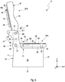
- the seat element 28 is in a seating position SP1, in which the first tread 30 faces the seat base 15 and the seat surface 29 faces away from the seat base 15.
- the backrest 42 is also in a sitting position SP2. In the sitting position SP2 of the backrest 42, the backrest 42 or the backrest seating surface 43 is positioned upright relative to the seat base 15. In particular, the backrest 42 is oriented approximately vertically with respect to the seat base 15.
- the second step surface 44 is inclined at an angle of inclination ⁇ relative to the first step surface 30.
- the angle of inclination ⁇ is preferably 90 ° to 110 °, more preferably 100 ° ⁇ 5 °, more preferably 100 ° ⁇ 3 °, more preferably 100 ° ⁇ 1 °, more preferably exactly 100 °.
- the angle of inclination ⁇ can be adjustable.
- the seat 14 can be used in the manner of a conventional seat. That is, a user can sit on the seat 14.
- both the seat element 28 and the backrest 42 are in the respective seating position SP1, SP2, the planes E1, E2 are inclined relative to one another at the angle of inclination ⁇ . That is, the planes E1, E2 intersect at the angle of inclination ⁇ .
- First step position TP1 shown in which the first step surface 30 faces away from the seat base 15 and the seat surface 29 faces the seat base 15, is first, as in FIG Fig. 5 shown, the seat element 28 is lifted from the seat base 15.
- the seat element 28 is first pivoted about the first axis of rotation M1 with the aid of the first pivoting device 34.
- a pivot angle ⁇ between the second axis of rotation M2 and a horizontal H can be, for example, approximately 45 °.
- the seat element 28 Before pivoting the seat element 28 about the first axis of rotation M1, the seat element 28 can be unlocked.
- a locking device for example in the form of a spring-loaded bolt, can be provided.
- the seat element 28 After the pivoting of the seat element 28 about the first axis of rotation M1, the seat element 28 is displaced linearly against the spring preload of the spring element 40 along the second axis of rotation M2 in order to move the seat element 28 from the position shown in FIG 2 to 4 , 6 and 7 shown in the non-shifted position P1 in the Fig. 5 shown shifted position P2.
- the seat element 28 In the displaced position P2, the seat element 28 is arranged so far from the seat base 15 that the seat element 28 about the second axis of rotation M2 by a pivoting angle ⁇ of 180 ° ( Fig. 3 ) can be pivoted.
- the first tread 30 is now facing away from the seat base 15 and the seat surface 29 is facing the seat base. This means that the seat element 28 is rotated by 180 °.
- a direction of rotation D of the seat element 28 can, as in FIG Fig. 5 shown, be oriented clockwise or counterclockwise.
- the movement of the seat element 28 from the non-displaced position P1 into the displaced position P2 is in FIG Fig. 5 indicated by means of an arrow 51.
- the seat element 28 is moved from the displaced position P2 into the non-displaced position P1 and pivoted back about the first axis of rotation M1, so that the support sections 31, 32 rest on the seat base 15 or on the support element 33.
- the movement of the seat element 28 from the displaced position P2 into the non-displaced position P1 is in FIG Fig. 6 indicated by an arrow 52.
- the first step surface 30 can be entered by the user.
- the seat 14 can now be used as a standing platform in such a way that the user can see out of the roof hatch 13 and, for example, can operate the weapon mounted on or on the roof 12.
- the backrest 42 is first unlocked with the aid of the locking device 47, so that the backrest 42 with the help of the second pivoting device 45 about the third axis of rotation M3 is pivotable in the direction of the seat member 28.
- the backrest 42 is pivoted clockwise about the third axis of rotation M3.
- This pivoting movement is in the Fig. 7 indicated by means of an arrow 53.
- the backrest 42 is then locked or locked again in the second step position TP2 with the aid of the locking device 47.
- the second step surface 44 can now also serve as a standing platform.
- the first tread surface 30 can serve as a climbing aid to the second tread surface 44.
- the seat 14 can now be used as a two-stage standing platform.
- the second tread surface 44 is arranged parallel to the first tread surface 30 and at a distance from it in the vertical direction z.
- “parallel” can also include the step surfaces 30, 44 being slightly inclined to one another, for example at an inclination angle of 1 ° to 20 °. If both the seat element 28 and the backrest 42 are in the respective pedal position TP1, TP2, the planes E1, E2 are arranged parallel to one another and spaced apart from one another.
- the support bracket 48 can be pivoted about the shaft 49 in such a way that the support bracket 48 is supported either on the first tread 30 or on the seat base 15 or on the support element 33.
- This pivoting movement is in the Fig. 7 indicated by means of an arrow 54.
- a higher weight can be applied to the second tread surface 44.
- the support bracket 48 is provided with the reference symbol 48 ′ in a folded-in position and with the reference symbol 48 in a folded-out position.
Landscapes
- Engineering & Computer Science (AREA)
- Aviation & Aerospace Engineering (AREA)
- Transportation (AREA)
- Mechanical Engineering (AREA)
- Seats For Vehicles (AREA)
Description
- Die vorliegende Erfindung betrifft einen Sitz für ein Nutzfahrzeug und ein Nutzfahrzeug mit einem derartigen Sitz.
- Bei Nutzfahrzeugen, insbesondere bei Lastkraftwagen, für militärische Anwendungen ist meist zwischen einem in einem Fahrerhaus angeordneten Fahrersitz und einem Beifahrersitz ein Mittelsitz vorgesehen. Der Mittelsitz soll dazu dienen, über eine an dem Fahrerhaus vorgesehene Dachluke eine auf oder an dem Dach montierte Waffe bedienen zu können. Hierzu ist es erforderlich, an dem Mittelsitz eine Trittfläche vorzusehen.
- Die
EP 1 832 468 A1 zeigt einen auf einer Oberseite gepolsterten Sitz, insbesondere eines Lastkraftwagens, wobei der Sitz über einen Schwenk-Drehmechanismus verfügt, mit dessen Hilfe der Sitz zwangsgeführt in eine mit der Oberseite nach unten weisende Position bringbar ist und mindestens einem weiteren Zusatznutzen zugänglich ist. - Die
EP 3 002 541 A1 beschreibt einen Sitz für ein Fahrzeug mit einer Rückenlehne und einer Sitzfläche, wobei der Sitz ein klappbares Tablett umfasst, das in Bezug auf die Rückenlehne angelenkt ist, wobei das Tablett in einer in einer Aufnahme der Rückenlehne an einer Frontfläche der letzteren eingeklappten Position positioniert werden kann, die den Rücken eines auf dem Sitz sitzenden Benutzers aufnehmen soll, wobei der Sitz Armlehnen umfasst, auf denen das Tablett in einer auseinandergeklappten Position abgestützt wird. - Die
DE 10 2012 012 505 A1 zeigt eine Sitzbank für ein Kraftfahrzeug. Die Sitzbank umfasst ein Gestell, das eine Stütze bildet, eine erste Sitzfläche und eine erste Rückenlehne, die auf dem Gestell montiert sind, wobei die erste Sitzfläche und/oder die erste Rückenlehne zwischen einer Benutzungsstellung und einer Nichtbenutzungsstellung verschiebbar sind, wobei das Gestell einen Stauraum unter der ersten Sitzfläche begrenzt, eine Klappe, die auf dem Gestell zwischen einer geschlossenen Stellung, in der der Stauraum verschlossen ist, und einer geöffneten Stellung, in der der Stauraum freigegeben ist, bewegbar montiert ist, und eine Sicherheitsvorrichtung, die ausgebildet ist, um die Verschiebung der Klappe aus ihrer geschlossenen Stellung in ihre geöffnete Stellung nur dann zu erlauben wenn die erste Sitzfläche oder die erste Rückenlehne in der Nichtbenutzungsstellung positioniert ist und wenn die zweite Sitzfläche oder die zweite Rückenlehne in der Nichtbenutzungsstellung positioniert ist. - Vor diesem Hintergrund besteht eine Aufgabe der vorliegenden Erfindung darin, einen verbesserten Sitz für ein Nutzfahrzeug zur Verfügung zu stellen.
- Demgemäß wird ein Sitz für ein Nutzfahrzeug, insbesondere für ein militärisches Nutzfahrzeug, vorgeschlagen. Der Sitz umfasst einen Sitzsockel, ein Sitzelement, das eine Sitzfläche und eine erste Trittfläche aufweist, eine erste Schwenkeinrichtung zum Verschwenken des Sitzelements derart, dass das Sitzelement von einer Sitzposition, in der die erste Trittfläche dem Sitzsockel zugewandt ist, in eine erste Trittposition, in der die erste Trittfläche dem Sitzsockel abgewandt ist, verschwenkbar ist, eine Rückenlehne, die eine Rückenlehnensitzfläche und eine zweite Trittfläche aufweist, und eine zweite Schwenkeinrichtung zum Verschwenken der Rückenlehne derart, dass die Rückenlehne von einer Sitzposition, in der die Rückenlehnensitzfläche relativ zu dem Sitzsockel aufrecht positioniert ist, in eine zweite Trittposition, in der die zweite Trittfläche parallel zu der ersten Trittfläche angeordnet ist, verschwenkbar ist.
- Dadurch, dass eine erste Trittfläche und eine zweite Trittfläche vorgesehen sind, können im Vergleich zu bekannten Sitzen für Nutzfahrzeuge zwei Stehhöhen verwirklicht werden, wobei die erste Trittfläche als Aufstiegshilfe zur zweiten Trittfläche dienen kann. Hierdurch werden zwei Stehniveaus verwirklicht, wodurch beispielweise Benutzer unterschiedlichster Körpergrößen den Sitz nutzen können oder der Benutzer je nach verwendeter Trittfläche weiter oder weniger weit aus einer Dachluke des Nutzfahrzeugs heraussehen kann.
- Der Sitz ist vorzugsweise ein Mittelsitz. Das heißt, der Sitz kann zwischen einem Fahrersitz und einem Beifahrersitz des Nutzfahrzeugs angeordnet sein. Der Sitz ist insbesondere in einem Fahrerhaus des Nutzfahrzeugs vorgesehen. Der Sitzsockel kann auch als Sitzfuß bezeichnet werden. Der Sitzsockel weist vorzugsweise eine quaderförmige oder kastenförmige Geometrie auf und kann ein aus Stahlplatten gefertigtes Bauteil sein.
- Vorzugsweise umfasst der Sitzsockel eine Vorderwand oder Vorderseite, eine beabstandet von der Vorderseite und parallel zu der Vorderseite angeordnete Rückwand oder Rückseite, zwei beabstandet voneinander und parallel zueinander angeordnete Seitenwände oder Seiten, eine Oberseite und eine Unterseite. Die Oberseite und die Unterseite können offen oder geschlossen sein. Vorzugsweise sind an den Seiten und der Rückseite zugewandt sich über die Oberseite hinaus erstreckende Sitzsockelwangen vorgesehen. Vorzugsweise ist das Sitzelement mit Hilfe der ersten Schwenkeinrichtung an den Sitzsockelwangen gelagert. Demgemäß ist auch die Rückenlehne mit Hilfe der zweiten Schwenkeinrichtung an den Sitzsockelwangen gelagert. Die Sitzsockelwangen sind im Bereich der Rückseite des Sitzsockels vorgesehen.
- Die Sitzfläche und die erste Trittfläche des Sitzelements sind vorzugsweise an einander gegenüberliegenden Seiten des Sitzelements vorgesehen. Insbesondere ist die Sitzfläche vorderseitig an dem Sitzelement vorgesehen, und die erste Trittfläche ist rückseitig an dem Sitzelement vorgesehen. Die Sitzfläche kann aus Stoff, Kunstleder oder dergleichen gefertigt sein. Die Sitzfläche kann beispielsweise eine Polsterung, insbesondere in Form einer Schaumstoffpolsterung, aufweisen. Die Sitzfläche kann daher auch als Sitzpolster bezeichnet werden. Alternativ kann die Sitzfläche auch ohne eine derartige Polsterung ausgeführt sein. Beispielsweise kann die Sitzfläche in diesem Fall eine Sitzschale sein, die beispielsweise aus Holz oder einem Verbundmaterial, wie beispielsweise einem faserverstärkten Kunststoffmaterial, gefertigt ist.
- Die erste Trittfläche ist vorzugweise aus einem Stahlblech oder Aluminiumblech gefertigt. Die erste Trittfläche kann auch als untere Trittfläche, erste Trittplatte, untere Trittplatte, erstes Trittblech oder unteres Trittblech bezeichnet werden. Alternativ zu einem Metallwerkstoff kann die erste Trittfläche auch aus einem Verbundmaterial, wie beispielsweise aus einem faserverstärkten Kunststoff oder dergleichen, gefertigt sein. Die erste Trittfläche ist trittsicher, rutschsicher oder rutschfest ausgebildet. Hierzu kann die erste Trittfläche eine Oberflächenstrukturierung aufweisen. Beispielsweise kann die erste Trittfläche ein Riffelblech sein.
- In der Sitzposition des Sitzelements ist die erste Trittfläche dem Sitzsockel, insbesondere dessen Oberseite, zugewandt und die Sitzfläche ist dem Sitzsockel, insbesondere dessen Oberseite, abgewandt. Die Sitzposition des Sitzelements kann auch als erste Sitzposition oder Sitzelementsitzposition bezeichnet werden. In der ersten Trittposition des Sitzelements ist die erste Trittfläche dem Sitzsockel abgewandt und die Sitzfläche ist dem Sitzsockel zugewandt. Das Sitzelement kann sich auf der Oberseite des Sitzsockels abstützen. Alternativ kann zwischen der Oberseite des Sitzsockels und dem Sitzelement auch ein Abstützelement vorgesehen sein, auf dem sich das Sitzelement sowohl in der Sitzposition als auch in der ersten Trittposition abstützen kann. Das Abstützelement kann leistenförmig sein. Das Abstützelement kann daher auch als Abstützleiste bezeichnet werden. Es können auch zwei Abstützelemente vorgesehen sein. In diesem Fall kann dann jeder Seite des Sitzsockels ein Abstützelement zugeordnet sein.
- Die zweite Trittfläche ist vorzugweise aus einem Stahlblech oder Aluminiumblech gefertigt. Die zweite Trittfläche kann auch als obere Trittfläche, zweite Trittplatte, obere Trittplatte, zweites Trittblech oder oberes Trittblech bezeichnet werden. Beispielsweise kann die zweite Trittfläche ein Riffelblech sein. Alternativ kann die zweite Trittfläche, wie die erste Trittfläche, aus einem Verbundmaterial, insbesondere aus einem faserverstärkten Kunststoff oder dergleichen, gefertigt sein. Auch die zweite Trittfläche ist trittsicher, rutschsicher oder rutschfest. Das heißt, auch die zweite Trittfläche kann eine Oberflächenstrukturierung aufweisen.
- Die Rückenlehnensitzfläche und die zweite Trittfläche der Rückenlehne sind vorzugsweise auf einander gegenüberliegenden Seiten der Rückenlehne vorgesehen. Insbesondere ist die Rückenlehnensitzfläche vorderseitig an der Rückenlehne vorgesehen, und die zweite Trittfläche ist rückseitig an der Rückenlehne vorgesehen. Die Rückenlehnensitzfläche kann aus Stoff, Kunstleder oder dergleichen gefertigt sein. Die Rückenlehnensitzfläche kann, wie die Sitzfläche, eine Polsterung, insbesondere eine Schaumstoffpolsterung, aufweisen. Die Rückenlehnensitzfläche kann daher auch als Rückenlehnenpolster bezeichnet werden. Alternativ kann die Rückenlehnensitzfläche auch ohne eine derartige Polsterung ausgebildet sein. Beispielsweise kann die Rückenlehnensitzfläche in diesem Fall eine Rückenlehnensitzschale sein, die beispielsweise aus Holz oder einem Verbundmaterial, wie beispielsweise einem faserverstärkten Kunststoffmaterial, gefertigt ist. Die Sitzfläche und die Rückenlehnensitzfläche sind bevorzugt ergonomisch an den Benutzer angepasst. Das heißt, die Sitzfläche und die Rückenlehnensitzfläche können beliebig geformt, beispielsweise in Form einer Freiformfläche, sein.
- Die Sitzposition der Rückenlehne kann auch als zweite Sitzposition oder Rückenlehnensitzposition bezeichnet werden. Dass die die Rückenlehnensitzfläche in der Sitzposition der Rückenlehne relativ zu dem Sitzsockel "aufrecht" positioniert ist, meint, dass die Rückenlehne beziehungsweise die Rückenlehnensitzfläche annähernd senkrecht zu dem Sitzsockel beziehungsweise zu dessen Oberseite orientiert ist. Vorzugsweise ist die Rückenlehne in Bezug auf die Sitzfläche in ihrer Sitzposition jedoch leicht zurück geneigt. Beispielsweise kann die zweite Trittfläche dann, wenn sich die Rückenlehne in ihrer Sitzposition befindet, in einem definierten Neigungswinkel zu der ersten Trittfläche beziehungsweise zu der Oberseite des Sitzsockels orientiert sein. Bevorzugt befindet sich dann auch das Sitzelement in seiner Sitzposition, so dass die erste Trittfläche dem Sitzsockel zugewandt ist. Der Neigungswinkel kann als Rückenlehnenneigungswinkel bezeichnet werden. Dieser Neigungswinkel beträgt bevorzugt 90° bis 110°, weiter bevorzugt 100° ± 5°, weiter bevorzugt 100° ± 3°, weiter bevorzugt 100° ± 1°, weiter bevorzugt genau 100°. Der Neigungswinkel α kann einstellbar sein.
- Vorzugsweise sind die erste Trittfläche und die zweite Trittfläche dann, wenn sich das Sitzelement in der ersten Trittposition und die Rückenlehne in der zweiten Trittposition befindet, parallel zueinander und in einer Hochrichtung des Sitzes beabstandet voneinander angeordnet. Unter "parallel" ist vorliegend jedoch auch zu verstehen, dass die erste Trittfläche und die zweite Trittfläche auch leicht geneigt zueinander angeordnet sein können. Beispielsweise können die erste Trittfläche und die zweite Trittfläche in einem Neigungswinkel von 1° bis 20° zueinander geneigt sein.
- Insbesondere spannen die erste Trittfläche und die zweite Trittfläche jeweils eine Ebene, insbesondere eine der ersten Trittfläche zugeordnete erste Ebene und eine der zweiten Trittfläche zugeordnete zweite Ebene, auf. Diese beiden Ebenen, die auch als Haupterstreckungsebenen der Trittflächen bezeichnet werden können, sind dann, wenn sich sowohl das Sitzelement als auch die Rückenlehne in der jeweiligen Trittposition befindet, wie zuvor erläutert, parallel zueinander orientiert. Für den Fall, dass sich sowohl das Sitzelement als auch die Rückenlehne in der jeweiligen Sitzposition befindet, sind die Ebenen in dem zuvor erläuterten Neigungswinkel relativ zueinander geneigt. Das heißt, in diesem Fall schneiden sich die Ebenen.
- Bevorzugt ist die zweite Schwenkeinrichtung dazu eingerichtet, die Rückenlehne als Ganzes zu verschwenken. Insbesondere wird die Rückenlehne bei dem Verschwenken derselben von ihrer Sitzposition in die zweite Trittposition nach vorne umgeklappt oder nach vorne geklappt. Unter "nach vorne" ist vorliegend in Richtung auf das Sitzelement beziehungsweise auf den Sitzsockel hinzu zu verstehen. Bevorzugt wird die Rückenlehne bei dem Verschwenken derselben von ihrer Sitzposition in die zweite Trittposition um den zuvor erwähnten Neigungswinkel verschwenkt oder umgeklappt.
- Gemäß einer Ausführungsform weist die erste Schwenkeinrichtung eine erste Drehachse, um die das Sitzelement drehbar gelagert ist, und eine zweite Drehachse, um die das Sitzelement drehbar gelagert ist, auf, wobei die erste Drehachse senkrecht zu der zweiten Drehachse orientiert ist.
- Unter "senkrecht" ist vorliegend ein Winkel von bevorzugt 90° ± 10°, weiter bevorzugt von 90° ± 5°, weiter bevorzugt von 90° ± 1°, weiter bevorzugt von genau 90° zu verstehen. Die erste Schwenkeinrichtung kann auch als Verschwenkeinrichtung oder Schwenk- und Dreheinrichtung bezeichnet werden. Vorzugsweise sind an den Seiten beziehungsweise an den Sitzsockelwangen des Sitzsockels mehrere Lagerstellen vorgesehen. Dabei ist der ersten Drehachse eine erste Welle der ersten Schwenkeinrichtung zugeordnet, die an den entsprechenden Lagerstellen des Sitzsockels drehbar gelagert ist. Hierzu können Wälzlager oder Gleitlager vorgesehen sein. Alternativ kann die erste Achse auch an den Lagerstellen drehfest gelagert sein und das Sitzelement ist entsprechend drehbar um die Welle gelagert. Der zweiten Drehachse ist vorzugsweise eine zweite Welle der ersten Schwenkeinrichtung zugeordnet. Das heißt, die erste Welle ist senkrecht zu der zweiten Welle orientiert. Die erste Welle ist bevorzugt rotationssymmetrisch zu der ersten Drehachse aufgebaut, und die zweite Welle ist bevorzugt rotationssymmetrisch zu der zweiten Drehachse aufgebaut.
- Gemäß einer weiteren Ausführungsform schneidet die erste Drehachse die zweite Drehachse.
- Das heißt, die erste Drehachse und die zweite Drehachse spannen eine gemeinsame Ebene auf. Die erste Drehachse ist dabei bevorzugt parallel zu einer Breitenrichtung des Sitzes orientiert, und die zweite Drehachse ist bevorzugt parallel zu einer Tiefenrichtung des Sitzes orientiert.
- Gemäß einer weiteren Ausführungsform ist das Sitzelement zum Verschwenken desselben von der Sitzposition in die erste Trittposition mit Hilfe der ersten Schwenkeinrichtung zuerst um einen ersten Verschwenkwinkel um die erste Drehachse verschwenkbar, wobei das Sitzelement nach dem Verschwenken um die erste Drehachse um einen zweiten Verschwenkwinkel um die zweite Drehachse verschwenkbar ist.
- Das heißt, zum Verschwenken des Sitzelements von der Sitzposition in die erste Trittposition wird das Sitzelement in zwei Schritten zunächst um die erste Drehachse und anschließend um die zweite Drehachse verschwenkt. Das heißt, zunächst wird das Sitzelement von dem Sitzsockel abgehoben und um die erste Drehachse verschwenkt. Anschließend wird das um den ersten Verschwenkwinkel verschwenkte Sitzelement nun noch um den zweiten Verschwenkwinkel um die zweite Drehachse verschwenkt. Anschließend wird das Sitzelement wieder um die erste Drehachse zurück verschwenkt und auf dem Sitzsockel abgelegt. Dabei kann das Sitzelement sowohl in der Sitzposition als auch in der ersten Trittposition mit dem Sitzsockel verriegelt oder verrastet werden. Hierzu kann eine Verriegelungseinrichtung vorgesehen sein.
- Gemäß einer weiteren Ausführungsform ist der zweite Verschwenkwinkel größer als der erste Verschwenkwinkel.
- Der zweite Verschwenkwinkel beträgt bevorzugt 180°. Der erste Verschwenkwinkel kann beispielsweise 30° bis 60°, bevorzugt 45°, betragen. Das heißt, das Sitzelement wird bei dem Verschwenken um die zweite Drehachse um 180° verdreht so dass entweder die Sitzfläche oder die erste Trittfläche dem Sitzsockel zugewandt ist.
- Gemäß einer weiteren Ausführungsform ist das Sitzelement an einer Rückseite des Sitzsockels um die erste Drehachse drehbar gelagert.
- Insbesondere ist das Sitzelement im Bereich der Rückseite um die erste Drehachse drehbar gelagert. Vorzugsweise sind an der Rückseite des Sitzsockels die Sitzsockelwangen vorgesehen, die mit den Seiten des Sitzsockels verbunden sind oder einteilig mit den Seiten ausgebildet sind. Das Sitzelement ist somit mit Hilfe der zuvor erwähnten ersten Welle, die an der Rückseite des Sitzsockels, insbesondere an den Sitzsockelwangen, gelagert ist, um die erste Drehachse drehbar an dem Sitzsockel gelagert.
- Gemäß einer weiteren Ausführungsform weist die erste Schwenkeinrichtung ein Kopplungselement auf, das um die erste Drehachse drehbar an dem Sitzsockel gelagert ist, wobei das Sitzelement um die zweite Drehachse drehbar an dem Kopplungselement gelagert ist.
- Vorzugsweise ist die zuvor erwähnte erste Welle der Schwenkeinrichtung in dem Kopplungselement aufgenommen. Dabei kann entweder die erste Welle drehbar in oder an dem Kopplungselement gelagert sein oder die erste Welle ist drehfest mit dem Kopplungselement verbunden und mit Hilfe der zuvor erwähnten Lagerstellen drehbar an dem Sitzsockel beziehungsweise an den Sitzsockelwangen gelagert. Zum Lagern des Sitzelements an dem Kopplungselement ist die zuvor erwähnte zweite Welle der ersten Schwenkeinrichtung vorgesehen. Die zweite Welle kann drehbar in oder an dem Kopplungselement oder drehbar in oder an dem Sitzelement gelagert sein. Hierzu können Wälzlager oder Gleitlager vorgesehen sein.
- Gemäß einer weiteren Ausführungsform ist das Sitzelement entlang der zweiten Drehachse linear verschiebbar, um das Sitzelement von einer unverschobenen Position in eine verschobene Position und umgekehrt zu verbringen.
- Die unverschobene Position kann auch als eingeschobene Position und die verschobene Position kann auch als ausgezogene Position bezeichnet werden. Insbesondere ist das Sitzelement entlang der zweiten Welle linear verschiebbar. Hierzu kann eine Linearführung vorgesehen sein. Dadurch, dass das Sitzelement von der unverschobenen Position in die verschobene Position verbringbar ist, kann das Sitzelement zum Verschwenken um die zweite Drehachse von dem Sitzsockel weg verlagert werden. Hierdurch wird ein Anstoßen des Sitzelements an dem Sitzsockel oder an der Rückenlehne bei dem Verschwenken desselben um die zweite Drehachse zuverlässig verhindert.
- Gemäß einer weiteren Ausführungsform ist das Sitzelement in Richtung der unverschobenen Position federvorgespannt.
- Hierdurch verlagert sich das Sitzelement dann, wenn keine in die verschobene Position orientierte Kraft mehr auf dasselbe aufgebracht wird, selbsttätig zurück in die unverschobene Position. Dies vereinfacht die Handhabung des Sitzes. Insbesondere kann der Sitz hierdurch auch einhändig bedient werden.
- Gemäß einer weiteren Ausführungsform weist die erste Schwenkeinrichtung zum Verbringen des Sitzelements von der unverschobenen Position in die verschobene Position und umgekehrt eine Teleskopwellenanordnung mit einer Welle und einem Federelement auf.
- Die Teleskopwellenanordnung bildet die zuvor erwähnte Linearführung des Sitzelements. Die Welle der Teleskopwellenanordnung entspricht der zuvor erwähnten zweiten Welle der ersten Schwenkeinrichtung. Das Federelement ist vorzugsweise eine Zylinderfeder, insbesondere eine Schraubenfeder, oder eine Gasdruckfeder. Das Federelement ist bevorzugt eine Druckfeder, die das Sitzelement in Richtung der unverschobenen Position federvorspannt. Das Federelement kann dabei in dem Sitzelement oder in dem zuvor erwähnten Kopplungselement aufgenommen sein. Vorzugsweise ist die Welle innerhalb des Federelements angeordnet. Hierdurch kann ein besonders kompakter Aufbau der Teleskopwellenanordnung erreicht werden. Die Teleskopwellenanordnung kann ferner eine Hohlwelle oder Hülse aufweisen, die in dem Sitzelement angeordnet ist. In der Hülse wiederum sind insbesondere das Federelement und die zweite Welle aufgenommen.
- Gemäß einer weiteren Ausführungsform weist die zweite Schwenkeinrichtung eine dritte Drehachse auf, um die die Rückenlehne drehbar gelagert ist, wobei die dritte Drehachse parallel zu der ersten Drehachse und senkrecht zu der zweiten Drehachse orientiert ist.
- Vorzugsweise ist die dritte Drehachse in der Hochrichtung und in der Tiefenrichtung des Sitzes beabstandet von der ersten Drehachse und parallel zu dieser angeordnet. Der dritten Drehachse ist vorzugsweise eine dritte Welle zugeordnet, die mit Hilfe der zuvor erwähnten Lagerstellen an dem Sitzsockel beziehungsweise an den Sitzsockelwangen des Sitzsockels gelagert ist. Dabei kann die dritte Welle drehbar an dem Sitzsockel gelagert sein und drehfest mit der Rückenlehne verbunden sein, oder die dritte Welle ist drehfest mit dem Sitzsockel verbunden und die Rückenlehne ist um die dritte Welle drehbar gelagert. Hierzu können Wälzlager oder Gleitlager vorgesehen sein.
- Gemäß einer weiteren Ausführungsform umfasst der Sitz eine Arretiereinrichtung zum Arretieren der Rückenlehne sowohl in der Sitzposition als auch in der zweiten Trittposition.
- Die Arretiereinrichtung ist dazu eingerichtet, die Rückenlehne formschlüssig zu arretieren. Eine formschlüssige Verbindung entsteht durch das Ineinander- oder Hintergreifen von mindestens zwei Verbindungspartnern. Die Arretiereinrichtung weist vorzugsweise die an dem Sitzsockel beziehungsweise an den Sitzsockelwangen vorgesehenen Lagerstellen in Form von Bohrungen sowie zumindest ein an der Rückenlehne vorgesehenes Arretierelement auf. Vorzugsweise sind zwei Arretierelemente vorgesehen, die an einander gegenüberliegenden Seiten der Rückenlehne positioniert sind. Die Arretierelemente können beispielsweise federvorgespannte Bolzen, insbesondere sogenannte Kugelsperrbolzen, sein. Umgekehrt können auch an den Sitzsockelwangen, insbesondere an den Lagerstellen, derartige Arretierelemente vorgesehen sein, die dazu eingerichtet sind, in entsprechende Ausnehmungen der Rückenlehne einzurasten oder einzugreifen. Zum Verbringen der Rückenlehne von der Sitzposition derselben in die zweite Trittposition wird die Arretiereinrichtung entriegelt und die Rückenlehne um die dritte Drehachse verschwenkt. Sobald sich die Rückenlehne in der zweiten Trittposition befindet, arretiert die Arretiereinrichtung die Rückenlehne selbsttätig. Umgekehrt verriegelt die Arretiereinrichtung die Rückenlehne auch bei einem Verschwenken derselben von der zweiten Trittposition in die Sitzposition wieder selbsttätig.
- Gemäß einer weiteren Ausführungsform weist die Rückenlehne einen Abstützbügel auf, der sich in der zweiten Trittposition auf dem Sitzsockel oder auf der ersten Trittfläche abstützt.
- Hierdurch kann die zweite Trittfläche mit einer besonders hohen Gewichtskraft belastet werden. Der Abstützbügel ist optional. Der Abstützbügel ist vorzugsweise rückseitig an der Rückenlehne, das heißt, an der zweiten Trittfläche, um eine vierte Drehachse drehbar gelagert.
- Gemäß einer weiteren Ausführungsform weist das Sitzelement Stützabschnitte auf, die sich in der ersten Trittposition auf dem Sitzsockel abstützen.
- Hierdurch wird vermieden, dass sich die Sitzfläche in der ersten Trittposition direkt auf dem Sitzsockel abstützt. Dadurch kann ein besonders sicherer Stand erzielt werden, wenn sich das Sitzelement in der ersten Trittposition befindet, da ein Verformen der möglicherweise gepolsterten Sitzfläche verhindert wird. Bevorzugt stützen sich die Stützabschnitte auf dem zuvor erwähnten Abstützelement ab.
- Ferner wird ein Nutzfahrzeug, insbesondere ein militärisches Nutzfahrzeug, mit zumindest einem derartigen Sitz vorgeschlagen.
- Das Nutzfahrzeug kann auch mehrere derartige Sitze umfassen. Wie zuvor erwähnt, umfasst das Nutzfahrzeug ein Fahrerhaus, in dem der Sitz angeordnet ist. Vorzugsweise ist der Sitz ein Mittelsitz, der zwischen dem Fahrersitz und dem Beifahrersitz angeordnet ist. Das Nutzfahrzeug umfasst vorzugsweise eine an oder auf einem Dach des Fahrerhauses montierte Waffe, die über eine an dem Dach vorgesehene Dachluke bedienbar ist. Das Fahrerhaus kann geschützt sein. Das heißt, das Fahrerhaus kann gegen Beschuss, Sprengfallen, Unkonventionelle Spreng- oder Brandvorrichtung (USBV), Minen oder dergleichen geschützt sein. Vorzugsweise ist der Sitz an einem Boden des Fahrerhauses montiert. Alternativ kann der Sitz auch an dem Dach des Fahrerhauses aufgehängt sein. Das Nutzfahrzeug ist bevorzugt ein Radfahrzeug. Bevorzugt weist das Nutzfahrzeug Allradantrieb auf. Das Nutzfahrzeug kann ein militärisch genutzter Lastkraftwagen sein.
- Weitere mögliche Implementierungen des Sitzes und/oder des Nutzfahrzeugs umfassen auch nicht explizit genannte Kombinationen von zuvor oder im Folgenden bezüglich der Ausführungsbeispiele beschriebenen Merkmalen oder Ausführungsformen. Dabei wird der Fachmann auch Einzelaspekte als Verbesserungen oder Ergänzungen zu der jeweiligen Grundform des Sitzes und/oder des Nutzfahrzeugs hinzufügen.
- Weitere vorteilhafte Ausgestaltungen und Aspekte des Sitzes und/oder des Nutzfahrzeugs sind Gegenstand der Unteransprüche sowie der im Folgenden beschriebenen Ausführungsbeispiele des Sitzes und/oder des Nutzfahrzeugs. Im Weiteren werden der Sitz und/oder das Nutzfahrzeug anhand von bevorzugten Ausführungsformen unter Bezugnahme auf die beigelegten Figuren näher erläutert.
- Fig. 1
- zeigt eine schematische Ansicht einer Ausführungsform eines Nutzfahrzeugs;
- Fig. 2
- zeigt eine Seitenansicht einer Ausführungsform eines Sitzes für das Nutzfahrzeug gemäß
Fig. 1 ; - Fig. 3
- zeigt eine Vorderansicht des Sitzes gemäß
Fig. 2 ; - Fig. 4
- zeigt eine schematische Ansicht einer Ausführungsform einer Schwenkeinrichtung für den Sitz gemäß
Fig. 2 ; - Fig. 5
- zeigt eine weitere schematische Seitenansicht des Sitzes gemäß
Fig. 2 ; - Fig. 6
- zeigt eine weitere schematische Seitenansicht des Sitzes gemäß
Fig. 2 ; und - Fig. 7
- zeigt eine weitere schematische Seitenansicht des Sitzes gemäß
Fig. 2 . - In den Figuren sind gleiche oder funktionsgleiche Elemente mit denselben Bezugszeichen versehen worden, sofern nichts anderes angegeben ist. Verdeckte Bauteile sind in den Figuren mit gestrichelten Linien dargestellt.
- Die
Fig. 1 zeigt eine schematische Seitenansicht einer Ausführungsform eines Nutzfahrzeugs 1. Das Nutzfahrzeug 1 ist insbesondere ein militärisches Nutzfahrzeug. Das Nutzfahrzeug 1 kann, wie in derFig. 1 gezeigt, ein Lastkraftwagen sein. Insbesondere ist das Nutzfahrzeug 1 ein geländegängiger Lastkraftwagen. Das Nutzfahrzeug 1 kann ein geschütztes Fahrzeug sein. Das Nutzfahrzeug 1 umfasst ein Fahrgestell 2 mit einer Vielzahl an Achsen 3 bis 5. Beispielsweise können drei derartige Achsen 3 bis 5 vorgesehen sein. Das heißt, das Nutzfahrzeug 1 ist ein Dreiachser. Das Nutzfahrzeug 1 umfasst bevorzugt einen Allradantrieb. Das heißt, alle Achsen 3 bis 5 sind angetrieben. Alternativ kann das Nutzfahrzeug 1 auch beliebig viele Achsen 3 bis 5 aufweisen. Das Nutzfahrzeug 1 kann, wie in derFig. 1 gezeigt, ein Radfahrzeug sein. Alternativ kann das Nutzfahrzeug 1 auch ein Kettenfahrzeug sein. - Das Nutzfahrzeug 1 umfasst weiterhin einen von dem Fahrgestell 2 getragenen Aufbau 6. Der Aufbau 6 kann beispielsweise eine Pritsche, einen Container, einen Koffer, einen Tank oder dergleichen umfassen. Weiterhin umfasst das Nutzfahrzeug 1 ein Fahrerhaus 7. Das Fahrerhaus 7 ist vorzugsweise gegen Beschuss, Sprengfallen, Unkonventionelle Spreng- oder Brandvorrichtung (USBV), Minen und dergleichen geschützt. Das Fahrerhaus 7 umfasst eine dem Aufbau 6 zugewandte Rückseite 8, eine dem Aufbau 6 abgewandte Vorderseite 9, zwei seitlich angeordnete Türen 10, einen Boden 11 und ein Dach 12.
- Auf oder an dem Dach 12 kann eine nicht gezeigte Waffe montiert sein. An dem Dach 12 ist eine Dachluke 13 vorgesehen. Die Dachluke 13 kann geöffnet und geschlossen werden. Beispielsweise kann die Dachluke 13 hierzu mit Hilfe eines Schwenkmechanismus verschwenkt werden. Über die geöffnete Dachluke 13 kann ein Innenraum I des Fahrerhauses 7 von einer Umgebung U des Nutzfahrzeugs 1 aus betreten und wieder verlassen werden. Insbesondere kann die Dachluke 13 dann geöffnet werden, wenn die auf oder an dem Dach 12 montierte Waffe zu bedienen ist.
- Die
Fig. 2 zeigt eine schematische Seitenansicht, und dieFig. 3 zeigt eine schematische Vorderansicht einer Ausführungsform eines Sitzes 14 für das Nutzfahrzeug 1. Vorzugsweise ist der Sitz 14 innerhalb des Fahrerhauses 7 und mittig in diesem angeordnet. Das heißt, der Sitz 14 ist unterhalb der Dachluke 13 angeordnet. Der Sitz 14 kann zwischen einem Fahrersitz und einem Beifahrersitz des Nutzfahrzeugs 1 angeordnet sein. Der Sitz 14 kann auch als Mittelsitz bezeichnet werden. Der Sitz 14 kann an dem Boden 11 des Fahrerhauses 7 montiert sein. Alternativ kann der Sitz 14 auch an dem Dach 12 des Fahrerhauses 7 aufgehängt sein. - Der Sitz 14 umfasst einen Sitzfuß oder Sitzsockel 15, der, wie zuvor erwähnt, mit dem Boden 11 oder dem Dach 12 des Fahrerhauses 7 gekoppelt sein kann. Der Sitzsockel 15 umfasst eine Vorderwand oder Vorderseite 16 sowie eine beabstandet zu der Vorderseite 16 und parallel zu der Vorderseite 16 angeordnete Rückwand oder Rückseite 17. Weiterhin weist der Sitzsockel 15 zwei parallel zueinander und beabstandet voneinander angeordnete Seitenwände oder Seiten 18, 19 auf. Ferner umfasst der Sitzsockel 15 eine Oberseite 20 und eine parallel zu der Oberseite 20 und beabstandet von dieser angeordnete Unterseite 21. Der Sitzsockel 15 ist so im Wesentlichen quaderförmig oder kastenförmig. Der Sitzsockel 15 kann nach oben, das heißt, an der Oberseite 20, offen oder geschlossen sein. Auch die Unterseite 21 kann offen oder geschlossen sein.
- Der Sitzsockel 15 weist weiterhin zwei an der Rückseite 17 vorgesehene und sich über die Oberseite 20 hinaus erstreckende Sitzsockelwangen 22, 23 auf. Die Sitzsockelwangen 22, 23 können einteilig, insbesondere materialeinstückig, mit den Seiten 18, 19 ausgebildet sein. Unter "einteilig" ist vorliegend zu verstehen, dass die Sitzsockelwangen 22, 23 und die jeweilige Seite 18, 19 jeweils ein gemeinsames einteiliges Bauteil bilden. Unter "materialeinstückig" ist vorliegend zu verstehen, dass die Sitzsockelwangen 22, 23 und die jeweilige Seite 18, 19 jeweils durchgehend aus demselben Material gefertigt sind.
- Beispielsweise können die Seiten 18, 19 mit der jeweiligen Sitzsockelwange 22, 23 als Stahlplatten ausgebildet sein. Der gesamte Sitzsockel 15 kann eine Schweißkonstruktion sein. Jede Sitzsockelwange 22, 23 weist mehrere Lagerstellen 24 bis 27 auf. Die Lagerstellen 24 bis 27 können beispielsweise als Durchbrüche in der jeweiligen Sitzsockelwange 22, 23 vorgesehen sein. Insbesondere können die Lagerstellen 24 bis 27 in den Sitzsockelwangen 22, 23 vorgesehene kreisrunde Bohrungen sein. Die Lagerstellen 24 bis 27 können Wälzlager oder Gleitlager umfassen.
- Der Sitz 14 umfasst weiterhin ein Sitzelement 28. Das Sitzelement 28 umfasst vorderseitig eine Sitzfläche 29 und rückseitig, das heißt, der Sitzfläche 29 abgewandt, eine erste Trittfläche 30. Die erste Trittfläche 30 kann auch als untere Trittfläche bezeichnet werden. Die erste Trittfläche 30 kann darüber hinaus auch als erste Trittplatte, untere Trittplatte, erstes Trittblech oder unteres Trittblech bezeichnet werden. Die Sitzfläche 29 kann ein Sitzpolster sein oder als solches bezeichnet werden. Die Sitzfläche 29 kann aus Stoff, Kunstleder oder dergleichen gefertigt sein. Die Sitzfläche 29 kann, beispielsweise mit Hilfe eines Schaumstoffmaterials, gepolstert sein. Die Sitzfläche 29 kann auch ohne eine derartige Polsterung ausgebildet sein. Beispielsweise kann die Sitzfläche 29 in diesem Fall eine Sitzschale sein, die beispielsweise aus Holz oder einem Verbundmaterial, wie beispielsweise einem faserverstärkten Kunststoffmaterial, gefertigt ist.
- Die erste Trittfläche 30 kann beispielsweise aus einem Stahlblech oder aus einem Aluminiumblech gefertigt sein. Die erste Trittfläche 30 ist trittsicher oder rutschsicher. Beispielsweise kann die erste Trittfläche 30 ein strukturiertes Stahlblech oder ein strukturiertes Aluminiumblech sein. Insbesondere kann die erste Trittfläche 30 ein Riffelblech sein. Alternativ kann die erste Trittfläche 30 auch aus einem Kunststoffmaterial oder einem Verbundmaterial, wie beispielsweise einem faserverstärkten Kunststoffmaterial, gefertigt sein. Auch in diesem Fall kann die erste Trittfläche 30 eine Oberflächenstrukturierung aufweisen. Die erste Trittfläche 30 spannt eine erste Ebene E1 auf. Die erste Ebene E1 kann auch als Haupterstreckungsebene der ersten Trittfläche 30 bezeichnet werden.
- Die erste Trittfläche 30 umfasst weiterhin zwei Stützabschnitte 31, 32, die beispielsweise als an der ersten Trittfläche 30 vorgesehene Abkantungen ausgebildet sind, die seitlich an der Sitzfläche 29 vorbeilaufen. Die Stützabschnitte 31, 32 sind dazu eingerichtet, sich auf der Oberseite 20 des Sitzsockels 15 oder auf einem an der Oberseite 20 vorgesehenen Abstützelement 33 abzustützen. Das Abstützelement 33 kann leistenförmig sein. Das Abstützelement 33 kann daher auch als Abstützleiste bezeichnet werden. Das Abstützelement 33 kann sich zwischen den Seiten 18, 19 erstrecken und beispielsweise mit diesen verschweißt sein. Das Abstützelement 33 ist optional. Alternativ können auch zwei Abstützelemente 33 vorgesehen sein. In diesem Fall kann dann jeder Seite 18, 19 des Sitzsockels 15 ein Abstützelement 33 zugeordnet sein.
- Ferner umfasst der Sitz 14 eine erste Schwenkeinrichtung 34 (
Fig. 4 ) zum Verschwenken des Sitzelements 28. Die erste Schwenkeinrichtung 34 kann auch als erste Verschwenkeinrichtung oder als Schwenk- und Dreheinrichtung bezeichnet werden. Die erste Schwenkeinrichtung 34 umfasst eine erste Welle 35, die in den Lagerstellen 27 der Sitzsockelwangen 22, 23 um eine erste Drehachse M1 drehbar an dem Sitzsockel 15 gelagert ist. Weiterhin umfasst die erste Schwenkeinrichtung 34 ein Kopplungselement 36, das das Sitzelement 28 mit der ersten Welle 35 koppelt. Das Kopplungselement 36 erstreckt sich leistenförmig zwischen den Seiten 18, 19 beziehungsweise zwischen den Sitzsockelwangen 22, 23. - Die erste Welle 35 kann drehbar in den Lagerstellen 27 der Sitzsockelwangen 22, 23 gelagert sein. In diesem Fall können die Lagerstellen 27 beispielsweise Wälzlager oder Gleitlager umfassen. Alternativ kann die erste Welle 35 an den Lagerstellen 27 drehfest gelagert sein und das Kopplungselement 36 kann sich um die erste Drehachse M1 herum um die erste Welle 35 drehen. In diesem Fall kann die erste Welle 35 in dem Kopplungselement 36 wälzgelagert oder gleitgelagert sein.
- Die erste Schwenkeinrichtung 34 umfasst weiterhin eine in dem Kopplungselement 36 gelagerte zweite Welle 37, um die das Sitzelement 28 um eine zweite Drehachse M2 drehbar gelagert ist. Dabei kann die zweite Welle 37 entweder drehbar in dem Sitzelement 28 gelagert sein oder die zweite Welle 37 ist drehbar in dem Kopplungselement 36 gelagert. Hierzu können Wälzlager oder Gleitlager vorgesehen sein. Die erste Drehachse M1 und die zweite Drehachse M2 beziehungsweise die erste Welle 35 und die zweite Welle 37 sind dabei senkrecht zueinander positioniert. Unter "senkrecht" ist vorliegend ein Winkel von bevorzugt 90° ± 10°, weiter bevorzugt von 90° ± 5°, weiter bevorzugt von 90° ± 1°, weiter bevorzugt von genau 90° zu verstehen. Dabei schneidet die erste Drehachse M1 die zweite Drehachse M2.
- Das Sitzelement 28 ist entlang der zweiten Drehachse M2 beziehungsweise entlang der zweiten Welle 37 linear verschiebbar. Diese lineare Verschiebbarkeit ist in der
Fig. 4 mit einem Doppelpfeil 38 angedeutet. Dabei kann das Sitzelement 28 von einer in denFig. 2 bis 4 ,6 und7 gezeigten eingeschobenen oder unverschobenen Position P1 in eine ausgezogene oder verschobene Position P2 (Fig. 5 ) und umgekehrt verbracht werden. Zum Verbringen des Sitzelements 28 von der unverschobenen Position P1 in die verschobene Position P2 und umgekehrt kann entweder das Sitzelement 28 linear gegenüber der zweiten Welle 37 bewegt werden, oder die zweite Welle 37 wird mitsamt dem Sitzelement 28 linear gegenüber dem Kopplungselement 36 bewegt. Hierzu kann eine Linearführung vorgesehen sein. - Bei der beispielhaften Ausführungsform der ersten Schwenkeinrichtung 34 gemäß der
Fig. 4 kann das Sitzelement 28 gegenüber der zweiten Welle 37 linear verschoben werden. Beispielsweise kann in dem Sitzelement 28 eine optionale Hohlwelle oder Hülse 39 vorgesehen sein, in der die zweite Welle 37 verschiebbar aufgenommen ist. Das Sitzelement 28 ist dabei in Richtung der unverschobenen Position P1 federvorgespannt. Das heißt, das Sitzelement 28 verbringt sich selbsttätig von der verschobenen Position P2 in die unverschobene Position P1 und kann gegen die Federvorspannung von der unverschobenen Position P1 in die verschobene Position P2 verbracht werden. - Hierzu umfasst die erste Schwenkeinrichtung 34 ein Federelement 40. Das Federelement 40 kann entweder, wie in der
Fig. 4 gezeigt, innerhalb des Sitzelements 28 angeordnet sein oder auch in dem Kopplungselement 36 aufgenommen sein. Die zweite Welle 37 und das Federelement 40 bilden eine Teleskopwellenanordnung 41 der ersten Schwenkeinrichtung 34. Auch die optionale Hülse 39 kann Teil der Teleskopwellenanordnung 41 sein. Das Federelement 40 ist bevorzugt eine Zylinderfeder, insbesondere eine Druckfeder. Das Federelement 40 kann auch eine Gasdruckfeder sein. Die zweite Welle 37 ist in dem Federelement 40 aufgenommen. Das Federelement 40 wiederum ist in der Hülse 39 aufgenommen. - Der Sitz 14 umfasst weiterhin eine Rückenlehne 42 mit einer Rückenlehnensitzfläche 43 und einer der Rückenlehnensitzfläche 43 abgewandten zweiten Trittfläche 44. Die zweite Trittfläche 44 kann auch als obere Trittfläche bezeichnet werden. Die zweite Trittfläche 44 kann darüber hinaus auch als zweite Trittplatte, obere Trittplatte, zweites Trittblech oder oberes Trittblech bezeichnet werden. Die Rückenlehnensitzfläche 43 kann auch als Rückenlehnenpolster bezeichnet werden. Die Rückenlehnensitzfläche 43 kann beispielsweise aus Stoff, Kunstleder oder dergleichen gefertigt sein. Die Rückenlehnensitzfläche 43 kann beispielsweise mit einem Schaumstoffmaterial gepolstert sein. Alternativ kann die Rückenlehnensitzfläche 43 auch ohne eine derartige Polsterung ausgebildet sein. Beispielsweise kann die Rückenlehnensitzfläche 43 in diesem Fall eine Rückenlehnensitzschale sein, die beispielsweise aus Holz oder einem Verbundmaterial, wie beispielsweise einem faserverstärkten Kunststoffmaterial, gefertigt ist.
- Die zweite Trittfläche 44 kann beispielsweise aus einem Stahlblech oder aus einem Aluminiumblech gefertigt sein. Die zweite Trittfläche 44 ist trittsicher oder rutschsicher. Beispielsweise kann die zweite Trittfläche 44 ein strukturiertes Stahlblech oder ein strukturiertes Aluminiumblech sein. Insbesondere kann die zweite Trittfläche 44 ein Riffelblech sein. Alternativ kann die zweite Trittfläche 44 auch aus einem Kunststoffmaterial oder einem Verbundmaterial, wie beispielsweise einem faserverstärkten Kunststoffmaterial, gefertigt sein. Auch in diesem Fall kann die zweite Trittfläche 44 eine Oberflächenstrukturierung aufweisen. Die zweite Trittfläche 44 spannt eine zweite Ebene E2 auf. Die zweite Ebene E2 kann auch als Haupterstreckungsebene der zweiten Trittfläche 44 bezeichnet werden.
- Der Rückenlehne 42 ist eine zweite Schwenkeinrichtung 45 des Sitzes 14 zugeordnet. Die zweite Schwenkeinrichtung 45 kann auch als zweite Verschwenkeinrichtung bezeichnet werden. Die zweite Schwenkeinrichtung 45 umfasst die Lagerstellen 25 der Sitzsockelwangen 22, 23 und eine in den Lagerstellen 25 gelagerte dritte Welle 46. Die dritte Welle 46 kann in den Lagerstellen 25 drehbar gelagert sein, oder die dritte Welle 46 ist in den Lagerstellen 25 drehfest aufgenommen und die Rückenlehne 42 ist um die dritte Welle 46 drehbar. Dementsprechend können auch Wälzlager oder Gleitlager vorgesehen sein.
- Insbesondere ist die Rückenlehne 42 mit Hilfe der zweiten Schwenkeinrichtung 45 um eine dritte Drehachse M3 verschwenkbar. Die dritte Drehachse M3 ist vorzugsweise parallel zu der ersten Drehachse M1 angeordnet und beabstandet von dieser positioniert. Das heißt, die dritte Drehachse M3 ist senkrecht zu der zweiten Drehachse M2 orientiert. In einer z-Richtung oder Hochrichtung z des Sitzes 14 betrachtet, ist die dritte Drehachse M3 oberhalb der Drehachsen M1, M2 positioniert. Dem Sitz 14 ist ferner noch eine x-Richtung oder Breitenrichtung x sowie eine y-Richtung oder Tiefenrichtung y zugeordnet. Die Richtungen x, y, z sind senkrecht zueinander orientiert und bilden ein Koordinatensystem des Sitzes 14. Dabei sind die Drehachsen M1, M3 parallel zu der Breitenrichtung x positioniert, und die zweite Drehachse M2 ist parallel zu der Tiefenrichtung y orientiert.
- Der Rückenlehne 42 ist weiterhin eine Arretiereinrichtung 47 zugeordnet. Die Arretiereinrichtung 47 umfasst die Lagerstellen 24, 26 der Sitzsockelwangen 22, 23 und ein nicht gezeigtes Arretierelement. Vorzugsweise sind zwei Arretierelemente vorgesehen, die an einander gegenüberliegenden Seiten der Rückenlehne 42 positioniert sind. Die Arretierelemente können beispielsweise an der Rückenlehne 42 vorgesehene federvorgespannte Bolzen, insbesondere sogenannte Kugelsperrbolzen, sein, die dazu eingerichtet sind, wahlweise in die beiden Lagerstellen 24 oder in die beiden Lagerstellen 26 formschlüssig einzugreifen, insbesondere einzuschnappen oder einzurasten. Die Lagerstellen 24, 26 können dann Ausnehmungen oder Bohrungen sein. Eine formschlüssige Verbindung entsteht durch das Ineinander- oder Hintergreifen von mindestens zwei Verbindungspartnern, in diesem Fall den Arretierelementen und den Lagerstellen 24, 26. Alternativ können auch an den beiden Lagerstellen 24, 26 derartige Arretierelemente vorgesehen sein, die dazu eingerichtet sind, in entsprechende Ausnehmungen an der Rückenlehne 42 formschlüssig einzugreifen.
- Der Sitz 14 umfasst weiterhin einen an der zweiten Trittfläche 44 montierten Abstützbügel 48. Der Abstützbügel 48 ist um eine vierte Drehachse M4 drehbar an der zweiten Trittfläche 44 gelagert. Rückseitig an der Rückenlehne 42, das heißt, an der zweiten Trittfläche 44, kann eine Welle 49 vorgesehen sein, mit deren Hilfe der Abstützbügel 48 um die vierte Drehachse M4 drehbar ist. Die Welle 49 kann in einem an der zweiten Trittfläche 44 vorgesehenen Lagerabschnitt 50 drehbar gelagert sein. Die vierte Drehachse M4 ist parallel zu den Drehachsen M1, M3 orientiert.
- Die Funktionalität des Sitzes 14 wird nachfolgend anhand der
Fig. 2 bis 7 erläutert. Wie dieFig. 2 und3 zeigen, befindet sich das Sitzelement 28 in einer Sitzposition SP1, in der die erste Trittfläche 30 dem Sitzsockel 15 zugewandt und die Sitzfläche 29 dem Sitzsockel 15 abgewandt ist. Ebenso befindet sich die Rückenlehne 42 in einer Sitzposition SP2. In der Sitzposition SP2 der Rückenlehne 42 ist die Rückenlehne 42 beziehungsweise die Rückenlehnensitzfläche 43 relativ zu dem Sitzsockel 15 aufrecht positioniert. Insbesondere ist die Rückenlehne 42 bezüglich des Sitzsockels 15 in etwa senkrecht orientiert. - Befinden sich das Sitzelement 28 und die Rückenlehne 42 in ihren Sitzpositionen SP1, SP2, ist die zweite Trittfläche 44 in einem Neigungswinkel α relativ zu der ersten Trittfläche 30 geneigt. Der Neigungswinkel α beträgt bevorzugt 90° bis 110°, weiter bevorzugt 100° ± 5°, weiter bevorzugt 100° ± 3°, weiter bevorzugt 100° ± 1°, weiter bevorzugt genau 100°. Der Neigungswinkel α kann einstellbar sein. Sobald sich das Sitzelement 28 und die Rückenlehne 42 in ihren Sitzpositionen SP1, SP2 befinden, kann der Sitz 14 in der Art und Weise eines herkömmlichen Sitzes eingesetzt werden. Das heißt, ein Benutzer kann auf dem Sitz 14 sitzen. Wenn sich sowohl das Sitzelement 28 als auch die Rückenlehne 42 in der jeweiligen Sitzposition SP1, SP2 befindet, sind die Ebenen E1, E2 in dem Neigungswinkel α relativ zueinander geneigt. Das heißt, die Ebenen E1, E2 schneiden sich unter dem Neigungswinkel α.
- Zum Verbringen des Sitzelements 28 von der Sitzposition SP1 in eine in den
Fig. 6 und7 gezeigte erste Trittposition TP1, in der die erste Trittfläche 30 dem Sitzsockel 15 abgewandt und die Sitzfläche 29 dem Sitzsockel 15 zugewandt ist, wird zunächst, wie in derFig. 5 gezeigt, das Sitzelement 28 von dem Sitzsockel 15 abgehoben. Hierbei wird das Sitzelement 28 mit Hilfe der ersten Schwenkeinrichtung 34 zunächst um die erste Drehachse M1 verschwenkt. Ein Verschwenkwinkel β zwischen der zweiten Drehachse M2 und einer Horizontalen H kann dabei beispielsweise etwa 45° betragen. Vor dem Verschwenken des Sitzelements 28 um die erste Drehachse M1 kann das Sitzelement 28 entriegelt werden. Hierzu kann eine Verriegelungsvorrichtung, beispielsweise in Form eines federvorgespannten Bolzens, vorgesehen sein. - Nach dem Verschwenken des Sitzelements 28 um die erste Drehachse M1 wird das Sitzelement 28 entgegen der Federvorspannung des Federelements 40 entlang der zweiten Drehachse M2 linear verlagert, um das Sitzelement 28 von der in den
Fig. 2 bis 4 ,6 und7 gezeigten unverschobenen Position P1 in die in derFig. 5 gezeigte verschobene Position P2 zu verbringen. In der verschobenen Position P2 ist das Sitzelement 28 so weit von dem Sitzsockel 15 entfernt angeordnet, dass das Sitzelement 28 um die zweite Drehachse M2 um einen Verschwenkwinkel γ von 180° (Fig. 3 ) verschwenkt werden kann. Die erste Trittfläche 30 ist nun dem Sitzsockel 15 abgewandt und die Sitzfläche 29 ist dem Sitzsockel zugewandt. Das heißt, das Sitzelement 28 wird um 180° verdreht. Eine Drehrichtung D des Sitzelements 28 kann dabei, wie in derFig. 5 gezeigt, im Uhrzeigersinn oder auch entgegen dem Uhrzeigersinn orientiert sein. Das Verbringen des Sitzelements 28 von der unverschobenen Position P1 in die verschobene Position P2 ist in derFig. 5 mit Hilfe eines Pfeils 51 angedeutet. - Anschließend wird, wie in der
Fig. 6 gezeigt, das Sitzelement 28 von der verschobenen Position P2 in die unverschobene Position P1 verbracht und um die erste Drehachse M1 zurück verschwenkt, so dass die Stützabschnitte 31, 32 auf dem Sitzsockel 15 beziehungsweise auf dem Abstützelement 33 aufliegen. Die Bewegung des Sitzelements 28 von der verschobenen Position P2 in die unverschobene Position P1 ist in derFig. 6 mit Hilfe eines Pfeils 52 angedeutet. Sobald sich das Sitzelement in der ersten Trittposition TP1 befindet, kann die erste Trittfläche 30 von dem Benutzer betreten werden. Der Sitz 14 kann nun als Stehpodest derart verwendet werden, dass der Benutzer aus der Dachluke 13 heraussehen kann und beispielsweise die auf oder an dem Dach 12 montierte Waffe bedienen kann. - Um nun die Rückenlehne 42 von ihrer Sitzposition SP2 in eine in der
Fig. 7 gezeigte zweite Trittposition TP2 zu verbringen, in der die zweite Trittfläche 44 parallel zu der ersten Trittfläche 30 angeordnet ist, wird die Rückenlehne 42 zunächst mit Hilfe der Arretiereinrichtung 47 entsperrt, so dass die Rückenlehne 42 mit Hilfe der zweiten Schwenkeinrichtung 45 um die dritte Drehachse M3 in Richtung auf das Sitzelement 28 zu verschwenkbar ist. Nach dem Entriegeln der Rückenlehne 42 wird diese im Uhrzeigersinn um die dritte Drehachse M3 verschwenkt. Diese Verschwenkbewegung ist in derFig. 7 mit Hilfe eines Pfeils 53 angedeutet. Anschließend wird die Rückenlehne 42 mit Hilfe der Arretiereinrichtung 47 in der zweiten Trittposition TP2 wieder verriegelt oder verrastet. Die zweite Trittfläche 44 kann nun ebenfalls als Stehpodest dienen. Die erste Trittfläche 30 kann dabei als Aufstiegshilfe zur zweiten Trittfläche 44 dienen. Zwischen dem Sitzelement 28 und der Rückenlehne 42 ist nun ein Freiraum oder Zwischenraum vorgesehen. Das heißt, die Rückenlehne 42 liegt nicht direkt auf dem Sitzelement 28 auf. - Der Sitz 14 kann nun als zweistufiges Stehpodest verwendet werden. Dabei ist die zweite Trittfläche 44 parallel zu der ersten Trittfläche 30 und in der Hochrichtung z beabstandet zu dieser angeordnet. Unter "parallel" kann vorliegend auch umfasst sein, dass die Trittflächen 30, 44 geringfügig zueinander geneigt sind, beispielsweise in einem Neigungswinkel von 1° bis 20°. Wenn sich sowohl das Sitzelement 28 als auch die Rückenlehne 42 in der jeweiligen Trittposition TP1, TP2 befindet, sind die Ebenen E1, E2 parallel zueinander und beabstandet voneinander angeordnet.
- Zusätzlich kann noch der Abstützbügel 48 um die Welle 49 derart verschwenkt werden, dass sich der Abstützbügel 48 entweder auf der ersten Trittfläche 30 oder auf dem Sitzsockel 15 beziehungsweise auf dem Abstützelement 33 abstützt. Diese Verschwenkbewegung ist in der
Fig. 7 mit Hilfe eines Pfeils 54 angedeutet. Hierdurch kann auf der zweiten Trittfläche 44 ein höheres Gewicht aufgebracht werden. In derFig. 7 ist der Abstützbügel 48 in einer eingeklappten Position mit dem Bezugszeichen 48' und in einer ausgeklappten Position mit dem Bezugszeichen 48 versehen. - Es ist auch möglich, nur die Rückenlehne 42 zu verschwenken, so dass sich das Sitzelement 28 in seiner Sitzposition SP1 und die Rückenlehne 42 in der zweiten Trittposition TP2 befindet. In diesem Fall dient dann nur die zweite Trittfläche 44 als Standfläche oder Stehpodest.
-
- 1
- Nutzfahrzeug
- 2
- Fahrgestell
- 3
- Achse
- 4
- Achse
- 5
- Achse
- 6
- Aufbau
- 7
- Fahrerhaus
- 8
- Rückseite
- 9
- Vorderseite
- 10
- Tür
- 11
- Boden
- 12
- Dach
- 13
- Dachluke
- 14
- Sitz
- 15
- Sitzsockel
- 16
- Vorderseite
- 17
- Rückseite
- 18
- Seite
- 19
- Seite
- 20
- Oberseite
- 21
- Unterseite
- 22
- Sitzsockelwange
- 23
- Sitzsockelwange
- 24
- Lagerstelle
- 25
- Lagerstelle
- 26
- Lagerstelle
- 27
- Lagerstelle
- 28
- Sitzelement
- 29
- Sitzfläche
- 30
- Trittfläche
- 31
- Stützabschnitt
- 32
- Stützabschnitt
- 33
- Abstützelement
- 34
- Schwenkeinrichtung
- 35
- Welle
- 36
- Kopplungselement
- 37
- Welle
- 38
- Doppelpfeil
- 39
- Hülse
- 40
- Federelement
- 41
- Teleskopwellenanordnung
- 42
- Rückenlehne
- 43
- Rückenlehnensitzfläche
- 44
- Trittfläche
- 45
- Schwenkeinrichtung
- 46
- Welle
- 47
- Arretiereinrichtung
- 48
- Abstützbügel
- 48'
- Abstützbügel
- 49
- Welle
- 50
- Lagerabschnitt
- 51
- Pfeil
- 52
- Pfeil
- 53
- Pfeil
- 54
- Pfeil
- D
- Drehrichtung
- E1
- Ebene
- E2
- Ebene
- H
- Horizontale
- I
- Innenraum
- M1
- Drehachse
- M2
- Drehachse
- M3
- Drehachse
- M4
- Drehachse
- P1
- Position
- P2
- Position
- SP1
- Sitzposition
- SP2
- Sitzposition
- TP1
- Trittposition
- TP2
- Trittposition
- U
- Umgebung
- x
- Breitenrichtung
- y
- Tiefenrichtung
- z
- Hochrichtung
- α
- Neigungswinkel
- β
- Verschwenkwinkel
- γ
- Verschwenkwinkel
Claims (15)
- Sitz (14) für ein Nutzfahrzeug (1), insbesondere für ein militärisches Nutzfahrzeug, mit:einem Sitzsockel (15),einem Sitzelement (28), das eine Sitzfläche (29) und eine erste Trittfläche (30) aufweist,einer ersten Schwenkeinrichtung (34) zum Verschwenken des Sitzelements (28) derart, dass das Sitzelement (28) von einer Sitzposition (SP1), in der die erste Trittfläche (30) dem Sitzsockel (15) zugewandt ist, in eine erste Trittposition (TP1), in der die erste Trittfläche (30) dem Sitzsockel (15) abgewandt ist, verschwenkbar ist,einer Rückenlehne (42), die eine Rückenlehnensitzfläche (43) und eine zweite Trittfläche (44) aufweist, undeiner zweiten Schwenkeinrichtung (45) zum Verschwenken der Rückenlehne (42) derart, dass die Rückenlehne (42) von einer Sitzposition (SP2), in der die Rückenlehnensitzfläche (43) relativ zu dem Sitzsockel (15) aufrecht positioniert ist, in eine zweite Trittposition (TP2), in der die zweite Trittfläche (44) parallel zu der ersten Trittfläche (30) angeordnet ist, verschwenkbar ist.
- Sitz nach Anspruch 1,
dadurch gekennzeichnet,
dass die erste Schwenkeinrichtung (34) eine erste Drehachse (M1), um die das Sitzelement (28) drehbar gelagert ist, und eine zweite Drehachse (M2), um die das Sitzelement (28) drehbar gelagert ist, aufweist, wobei die erste Drehachse (M1) senkrecht zu der zweiten Drehachse (M2) orientiert ist. - Sitz nach Anspruch 2,
dadurch gekennzeichnet,
dass die erste Drehachse (M1) die zweite Drehachse (M2) schneidet. - Sitz nach Anspruch 2 oder 3,
dadurch gekennzeichnet,
dass das Sitzelement (28) zum Verschwenken desselben von der Sitzposition (SP1) in die erste Trittposition (TP1) mit Hilfe der ersten Schwenkeinrichtung (34) zuerst um einen ersten Verschwenkwinkel (β) um die erste Drehachse (M1) verschwenkbar ist, wobei das Sitzelement (28) nach dem Verschwenken um die erste Drehachse (M1) um einen zweiten Verschwenkwinkel (γ) um die zweite Drehachse (M2) verschwenkbar ist. - Sitz nach Anspruch 4,
dadurch gekennzeichnet,
dass der zweite Verschwenkwinkel (γ) größer als der erste Verschwenkwinkel (β) ist. - Sitz nach einem der Ansprüche 2 - 5,
dadurch gekennzeichnet,
dass das Sitzelement (28) an einer Rückseite (17) des Sitzsockels (15) um die erste Drehachse (M1) drehbar gelagert ist. - Sitz nach einem der Ansprüche 2 - 6,
dadurch gekennzeichnet,
dass die erste Schwenkeinrichtung (34) ein Kopplungselement (36) aufweist, das um die erste Drehachse (M1) drehbar an dem Sitzsockel (15) gelagert ist, wobei das Sitzelement (28) um die zweite Drehachse (M2) drehbar an dem Kopplungselement (36) gelagert ist. - Sitz nach einem der Ansprüche 2 - 7,
dadurch gekennzeichnet,
dass das Sitzelement (28) entlang der zweiten Drehachse (M2) linear verschiebbar ist, um das Sitzelement (28) von einer unverschobenen Position (P1) in eine verschobene Position (P2) und umgekehrt zu verbringen. - Sitz nach Anspruch 8,
dadurch gekennzeichnet,
dass das Sitzelement (28) in Richtung der unverschobenen Position (P1) federvorgespannt ist. - Sitz nach Anspruch 8 oder 9,
dadurch gekennzeichnet,
dass die erste Schwenkeinrichtung (34) zum Verbringen des Sitzelements (28) von der unverschobenen Position (P1) in die verschobene Position (P2) und umgekehrt eine Teleskopwellenanordnung (41) mit einer Welle (37) und einem Federelement (40) aufweist. - Sitz nach einem der Ansprüche 2 - 10,
dadurch gekennzeichnet,
dass die zweite Schwenkeinrichtung (45) eine dritte Drehachse (M3) aufweist, um die die Rückenlehne (42) drehbar gelagert ist, wobei die dritte Drehachse (M3) parallel zu der ersten Drehachse (M1) und senkrecht zu der zweiten Drehachse (M2) orientiert ist. - Sitz nach einem der Ansprüche 1 - 11,
gekennzeichnet durch
eine Arretiereinrichtung (47) zum Arretieren der Rückenlehne (42) sowohl in der Sitzposition (SP2) als auch in der zweiten Trittposition (TP2). - Sitz nach einem der Ansprüche 1 - 12,
dadurch gekennzeichnet,
dass die Rückenlehne (42) einen Abstützbügel (48, 48') aufweist, der sich in der zweiten Trittposition (TP2) auf dem Sitzsockel (15) oder auf der ersten Trittfläche (30) abstützt. - Sitz nach einem der Ansprüche 1 - 13,
dadurch gekennzeichnet,
dass das Sitzelement (28) Stützabschnitte (31, 32) aufweist, die sich in der ersten Trittposition (TP1) auf dem Sitzsockel (15) abstützen. - Nutzfahrzeug, insbesondere militärisches Nutzfahrzeug, mit zumindest einem Sitz nach einem der Ansprüche 1 - 14.
Applications Claiming Priority (2)
| Application Number | Priority Date | Filing Date | Title |
|---|---|---|---|
| DE102018109130.3A DE102018109130A1 (de) | 2018-04-17 | 2018-04-17 | Sitz und Nutzfahrzeug |
| PCT/EP2018/079658 WO2019201462A1 (de) | 2018-04-17 | 2018-10-30 | Sitz und nutzfahrzeug |
Publications (2)
| Publication Number | Publication Date |
|---|---|
| EP3573858A1 EP3573858A1 (de) | 2019-12-04 |
| EP3573858B1 true EP3573858B1 (de) | 2020-07-29 |
Family
ID=64049261
Family Applications (1)
| Application Number | Title | Priority Date | Filing Date |
|---|---|---|---|
| EP18795589.3A Active EP3573858B1 (de) | 2018-04-17 | 2018-10-30 | Sitz und nutzfahrzeug |
Country Status (8)
| Country | Link |
|---|---|
| US (1) | US11014476B2 (de) |
| EP (1) | EP3573858B1 (de) |
| AU (1) | AU2018412624B2 (de) |
| DE (1) | DE102018109130A1 (de) |
| ES (1) | ES2820325T3 (de) |
| RU (1) | RU2735338C1 (de) |
| WO (1) | WO2019201462A1 (de) |
| ZA (1) | ZA201904721B (de) |
Families Citing this family (4)
| Publication number | Priority date | Publication date | Assignee | Title |
|---|---|---|---|---|
| RU2754830C2 (ru) * | 2020-02-10 | 2021-09-07 | Евгений Григорьевич Мельников | Откидное набок сиденье транспортного средства |
| GB2593720B (en) * | 2020-03-31 | 2022-03-23 | Mcmurtry Automotive Ltd | Vehicle seat |
| JP7556811B2 (ja) * | 2021-03-24 | 2024-09-26 | 近畿車輌株式会社 | 乗物用の椅子および乗物 |
| DE102024103387A1 (de) * | 2024-02-07 | 2025-08-07 | Aguti Produktentwicklung & Design Gmbh | Gurtgestell für einen Fahrzeugsitz |
Family Cites Families (9)
| Publication number | Priority date | Publication date | Assignee | Title |
|---|---|---|---|---|
| DE19820880C1 (de) * | 1998-05-09 | 2000-03-02 | Daimler Chrysler Ag | Fahrzeugsitz |
| DE20110630U1 (de) | 2001-06-27 | 2002-11-07 | Johnson Controls GmbH, 51399 Burscheid | Sitzanordnung mit verstellbarem Sitzsegment |
| RU48890U1 (ru) | 2005-05-13 | 2005-11-10 | Щербаков Валерий Тихонович | Транспортное сидение |
| AT502799B1 (de) | 2006-03-07 | 2007-06-15 | Man Nutzfahrzeuge Oesterreich | Sitz |
| DE102009038440B4 (de) * | 2009-08-21 | 2018-06-14 | GM Global Technology Operations LLC (n. d. Ges. d. Staates Delaware) | Kraftfahrzeug mit einer Sitzreihe mit zwei Außensitzen und einem Mittelsitz |
| FR2977203B1 (fr) * | 2011-06-28 | 2014-01-03 | Antolin Grupo Ing Sa | Banquette pour un vehicule automobile |
| US9145656B2 (en) * | 2014-01-15 | 2015-09-29 | Deere & Company | Configurable seat assembly for work vehicles |
| FR3026357B1 (fr) | 2014-09-25 | 2017-11-24 | Nexter Systems | Siege pour vehicule |
| US10160392B2 (en) * | 2017-01-31 | 2018-12-25 | Ford Global Technologies, Llc | Composite seat side storage bin |
-
2018
- 2018-04-17 DE DE102018109130.3A patent/DE102018109130A1/de not_active Ceased
- 2018-10-30 US US16/619,568 patent/US11014476B2/en active Active
- 2018-10-30 AU AU2018412624A patent/AU2018412624B2/en active Active
- 2018-10-30 ES ES18795589T patent/ES2820325T3/es active Active
- 2018-10-30 WO PCT/EP2018/079658 patent/WO2019201462A1/de not_active Ceased
- 2018-10-30 RU RU2019127541A patent/RU2735338C1/ru active
- 2018-10-30 EP EP18795589.3A patent/EP3573858B1/de active Active
-
2019
- 2019-07-18 ZA ZA2019/04721A patent/ZA201904721B/en unknown
Non-Patent Citations (1)
| Title |
|---|
| None * |
Also Published As
| Publication number | Publication date |
|---|---|
| US20200164777A1 (en) | 2020-05-28 |
| WO2019201462A1 (de) | 2019-10-24 |
| AU2018412624A1 (en) | 2019-11-07 |
| ZA201904721B (en) | 2020-02-26 |
| AU2018412624B2 (en) | 2020-09-03 |
| BR112019020323A2 (pt) | 2020-04-28 |
| US11014476B2 (en) | 2021-05-25 |
| DE102018109130A1 (de) | 2019-10-17 |
| RU2735338C1 (ru) | 2020-10-30 |
| EP3573858A1 (de) | 2019-12-04 |
| ES2820325T3 (es) | 2021-04-20 |
Similar Documents
| Publication | Publication Date | Title |
|---|---|---|
| EP3573858B1 (de) | Sitz und nutzfahrzeug | |
| DE60304991T2 (de) | Kopfstütze für kraftfahrzeuge | |
| DE2848268C2 (de) | ||
| DE68903290T2 (de) | Umklappbarer sitz, insbesondere ruecksitz fuer ein kraftfahrzeug. | |
| AT518405B1 (de) | Fahrerhauslagerung für ein kippbares Fahrerhaus eines Nutzfahrzeugs | |
| EP0899152B1 (de) | Sitz, insbesondere für eine dritte Sitzreihe eines Kraftfahrzeuges | |
| DE102005020335A1 (de) | Kraftfahrzeugsitz | |
| DE102012012850A1 (de) | Fahrzeugsitz | |
| DE2731386A1 (de) | Rechteckiger behaelter von der groesse eines wagenaufbaus, insbesondere container nach iso-norm | |
| EP2033842B1 (de) | Kraftfahrzeuginneneinrichtung mit einem verschwenkbaren Ladeboden zur Laderaumunterteilung | |
| DE19737712A1 (de) | Ladesystem für einen Stauraum eines Personenkraftwagens | |
| DE102018220638A1 (de) | Vorrichtung für ein Fahrzeug und ein Fahrzeug | |
| DE102018206971B4 (de) | Sattelschrank | |
| DE102006023176A1 (de) | Anordnung für einen Sitz für ein Fahrzeug zur Verringerung seiner Gesamtlängsabmessung | |
| DE102007052529B4 (de) | Ein Sitz und Sitzanordnung in einem Kraftfahrzeug | |
| DE2912405A1 (de) | Kraftfahrzeugsitz | |
| DE102010046562A1 (de) | Sitz oder Sitzanlage für ein Kraftfahrzeug und insbesondere einen Lieferwagen | |
| WO2019072847A1 (de) | Fahrzeugsitz mit einem easy-entry-mechanismus | |
| EP1873004B1 (de) | Kraftfahrzeugsitz mit einer Rückenlehne, die automatisch von der Gebrauchsstellung in die Nichtgebrauchsstellung verschwenkbar ist | |
| DE102018205232B3 (de) | Ladefläche in einem Fahrzeug | |
| DE202020100482U1 (de) | Kammer mit Toilette, und damit ausgestattetes Fahrzeug | |
| EP3785984B1 (de) | Sitzgestell für eine fahrzeugsitzanordnung | |
| DE2640895A1 (de) | Fahrerhaus eines kraftfahrzeuges | |
| DE9204215U1 (de) | Klappsitzbank | |
| DE102005012314B4 (de) | Stauvorrichtung für ein Kraftfahrzeug |
Legal Events
| Date | Code | Title | Description |
|---|---|---|---|
| STAA | Information on the status of an ep patent application or granted ep patent |
Free format text: STATUS: UNKNOWN |
|
| STAA | Information on the status of an ep patent application or granted ep patent |
Free format text: STATUS: THE INTERNATIONAL PUBLICATION HAS BEEN MADE |
|
| PUAI | Public reference made under article 153(3) epc to a published international application that has entered the european phase |
Free format text: ORIGINAL CODE: 0009012 |
|
| STAA | Information on the status of an ep patent application or granted ep patent |
Free format text: STATUS: REQUEST FOR EXAMINATION WAS MADE |
|
| 17P | Request for examination filed |
Effective date: 20190723 |
|
| AK | Designated contracting states |
Kind code of ref document: A1 Designated state(s): AL AT BE BG CH CY CZ DE DK EE ES FI FR GB GR HR HU IE IS IT LI LT LU LV MC MK MT NL NO PL PT RO RS SE SI SK SM TR |
|
| AX | Request for extension of the european patent |
Extension state: BA ME |
|
| RIN1 | Information on inventor provided before grant (corrected) |
Inventor name: ALLMANN, CHRISTIAN |
|
| GRAP | Despatch of communication of intention to grant a patent |
Free format text: ORIGINAL CODE: EPIDOSNIGR1 |
|
| STAA | Information on the status of an ep patent application or granted ep patent |
Free format text: STATUS: GRANT OF PATENT IS INTENDED |
|
| GRAS | Grant fee paid |
Free format text: ORIGINAL CODE: EPIDOSNIGR3 |
|
| INTG | Intention to grant announced |
Effective date: 20200525 |
|
| GRAA | (expected) grant |
Free format text: ORIGINAL CODE: 0009210 |
|
| STAA | Information on the status of an ep patent application or granted ep patent |
Free format text: STATUS: THE PATENT HAS BEEN GRANTED |
|
| AK | Designated contracting states |
Kind code of ref document: B1 Designated state(s): AL AT BE BG CH CY CZ DE DK EE ES FI FR GB GR HR HU IE IS IT LI LT LU LV MC MK MT NL NO PL PT RO RS SE SI SK SM TR |
|
| DAV | Request for validation of the european patent (deleted) | ||
| DAX | Request for extension of the european patent (deleted) | ||
| REG | Reference to a national code |
Ref country code: CH Ref legal event code: EP |
|
| REG | Reference to a national code |
Ref country code: AT Ref legal event code: REF Ref document number: 1295407 Country of ref document: AT Kind code of ref document: T Effective date: 20200815 |
|
| REG | Reference to a national code |
Ref country code: IE Ref legal event code: FG4D Free format text: LANGUAGE OF EP DOCUMENT: GERMAN |
|
| REG | Reference to a national code |
Ref country code: DE Ref legal event code: R096 Ref document number: 502018002030 Country of ref document: DE |
|
| REG | Reference to a national code |
Ref country code: CH Ref legal event code: NV Representative=s name: VALIPAT S.A. C/O BOVARD SA NEUCHATEL, CH |
|
| REG | Reference to a national code |
Ref country code: FI Ref legal event code: FGE |
|
| REG | Reference to a national code |
Ref country code: NL Ref legal event code: FP |
|
| REG | Reference to a national code |
Ref country code: SE Ref legal event code: TRGR |
|
| REG | Reference to a national code |
Ref country code: LT Ref legal event code: MG4D |
|
| PG25 | Lapsed in a contracting state [announced via postgrant information from national office to epo] |
Ref country code: GR Free format text: LAPSE BECAUSE OF FAILURE TO SUBMIT A TRANSLATION OF THE DESCRIPTION OR TO PAY THE FEE WITHIN THE PRESCRIBED TIME-LIMIT Effective date: 20201030 Ref country code: LT Free format text: LAPSE BECAUSE OF FAILURE TO SUBMIT A TRANSLATION OF THE DESCRIPTION OR TO PAY THE FEE WITHIN THE PRESCRIBED TIME-LIMIT Effective date: 20200729 Ref country code: BG Free format text: LAPSE BECAUSE OF FAILURE TO SUBMIT A TRANSLATION OF THE DESCRIPTION OR TO PAY THE FEE WITHIN THE PRESCRIBED TIME-LIMIT Effective date: 20201029 Ref country code: NO Free format text: LAPSE BECAUSE OF FAILURE TO SUBMIT A TRANSLATION OF THE DESCRIPTION OR TO PAY THE FEE WITHIN THE PRESCRIBED TIME-LIMIT Effective date: 20201029 Ref country code: PT Free format text: LAPSE BECAUSE OF FAILURE TO SUBMIT A TRANSLATION OF THE DESCRIPTION OR TO PAY THE FEE WITHIN THE PRESCRIBED TIME-LIMIT Effective date: 20201130 Ref country code: HR Free format text: LAPSE BECAUSE OF FAILURE TO SUBMIT A TRANSLATION OF THE DESCRIPTION OR TO PAY THE FEE WITHIN THE PRESCRIBED TIME-LIMIT Effective date: 20200729 |
|
| PG25 | Lapsed in a contracting state [announced via postgrant information from national office to epo] |
Ref country code: PL Free format text: LAPSE BECAUSE OF FAILURE TO SUBMIT A TRANSLATION OF THE DESCRIPTION OR TO PAY THE FEE WITHIN THE PRESCRIBED TIME-LIMIT Effective date: 20200729 Ref country code: RS Free format text: LAPSE BECAUSE OF FAILURE TO SUBMIT A TRANSLATION OF THE DESCRIPTION OR TO PAY THE FEE WITHIN THE PRESCRIBED TIME-LIMIT Effective date: 20200729 Ref country code: LV Free format text: LAPSE BECAUSE OF FAILURE TO SUBMIT A TRANSLATION OF THE DESCRIPTION OR TO PAY THE FEE WITHIN THE PRESCRIBED TIME-LIMIT Effective date: 20200729 Ref country code: IS Free format text: LAPSE BECAUSE OF FAILURE TO SUBMIT A TRANSLATION OF THE DESCRIPTION OR TO PAY THE FEE WITHIN THE PRESCRIBED TIME-LIMIT Effective date: 20201129 |
|
| REG | Reference to a national code |
Ref country code: ES Ref legal event code: FG2A Ref document number: 2820325 Country of ref document: ES Kind code of ref document: T3 Effective date: 20210420 |
|
| PG25 | Lapsed in a contracting state [announced via postgrant information from national office to epo] |
Ref country code: SM Free format text: LAPSE BECAUSE OF FAILURE TO SUBMIT A TRANSLATION OF THE DESCRIPTION OR TO PAY THE FEE WITHIN THE PRESCRIBED TIME-LIMIT Effective date: 20200729 Ref country code: EE Free format text: LAPSE BECAUSE OF FAILURE TO SUBMIT A TRANSLATION OF THE DESCRIPTION OR TO PAY THE FEE WITHIN THE PRESCRIBED TIME-LIMIT Effective date: 20200729 Ref country code: RO Free format text: LAPSE BECAUSE OF FAILURE TO SUBMIT A TRANSLATION OF THE DESCRIPTION OR TO PAY THE FEE WITHIN THE PRESCRIBED TIME-LIMIT Effective date: 20200729 Ref country code: DK Free format text: LAPSE BECAUSE OF FAILURE TO SUBMIT A TRANSLATION OF THE DESCRIPTION OR TO PAY THE FEE WITHIN THE PRESCRIBED TIME-LIMIT Effective date: 20200729 |
|
| REG | Reference to a national code |
Ref country code: DE Ref legal event code: R097 Ref document number: 502018002030 Country of ref document: DE |
|
| PG25 | Lapsed in a contracting state [announced via postgrant information from national office to epo] |
Ref country code: AL Free format text: LAPSE BECAUSE OF FAILURE TO SUBMIT A TRANSLATION OF THE DESCRIPTION OR TO PAY THE FEE WITHIN THE PRESCRIBED TIME-LIMIT Effective date: 20200729 |
|
| PLBE | No opposition filed within time limit |
Free format text: ORIGINAL CODE: 0009261 |
|
| STAA | Information on the status of an ep patent application or granted ep patent |
Free format text: STATUS: NO OPPOSITION FILED WITHIN TIME LIMIT |
|
| PG25 | Lapsed in a contracting state [announced via postgrant information from national office to epo] |
Ref country code: MC Free format text: LAPSE BECAUSE OF FAILURE TO SUBMIT A TRANSLATION OF THE DESCRIPTION OR TO PAY THE FEE WITHIN THE PRESCRIBED TIME-LIMIT Effective date: 20200729 Ref country code: LU Free format text: LAPSE BECAUSE OF NON-PAYMENT OF DUE FEES Effective date: 20201030 Ref country code: SK Free format text: LAPSE BECAUSE OF FAILURE TO SUBMIT A TRANSLATION OF THE DESCRIPTION OR TO PAY THE FEE WITHIN THE PRESCRIBED TIME-LIMIT Effective date: 20200729 |
|
| 26N | No opposition filed |
Effective date: 20210430 |
|
| REG | Reference to a national code |
Ref country code: BE Ref legal event code: MM Effective date: 20201031 |
|
| PG25 | Lapsed in a contracting state [announced via postgrant information from national office to epo] |
Ref country code: BE Free format text: LAPSE BECAUSE OF NON-PAYMENT OF DUE FEES Effective date: 20201031 |
|
| PG25 | Lapsed in a contracting state [announced via postgrant information from national office to epo] |
Ref country code: IE Free format text: LAPSE BECAUSE OF NON-PAYMENT OF DUE FEES Effective date: 20201030 |
|
| PG25 | Lapsed in a contracting state [announced via postgrant information from national office to epo] |
Ref country code: MT Free format text: LAPSE BECAUSE OF FAILURE TO SUBMIT A TRANSLATION OF THE DESCRIPTION OR TO PAY THE FEE WITHIN THE PRESCRIBED TIME-LIMIT Effective date: 20200729 Ref country code: CY Free format text: LAPSE BECAUSE OF FAILURE TO SUBMIT A TRANSLATION OF THE DESCRIPTION OR TO PAY THE FEE WITHIN THE PRESCRIBED TIME-LIMIT Effective date: 20200729 |
|
| PG25 | Lapsed in a contracting state [announced via postgrant information from national office to epo] |
Ref country code: MK Free format text: LAPSE BECAUSE OF FAILURE TO SUBMIT A TRANSLATION OF THE DESCRIPTION OR TO PAY THE FEE WITHIN THE PRESCRIBED TIME-LIMIT Effective date: 20200729 |
|
| PG25 | Lapsed in a contracting state [announced via postgrant information from national office to epo] |
Ref country code: SI Free format text: LAPSE BECAUSE OF FAILURE TO SUBMIT A TRANSLATION OF THE DESCRIPTION OR TO PAY THE FEE WITHIN THE PRESCRIBED TIME-LIMIT Effective date: 20200729 |
|
| REG | Reference to a national code |
Ref country code: CH Ref legal event code: U11 Free format text: ST27 STATUS EVENT CODE: U-0-0-U10-U11 (AS PROVIDED BY THE NATIONAL OFFICE) Effective date: 20251101 |
|
| PGFP | Annual fee paid to national office [announced via postgrant information from national office to epo] |
Ref country code: NL Payment date: 20251021 Year of fee payment: 8 |
|
| PGFP | Annual fee paid to national office [announced via postgrant information from national office to epo] |
Ref country code: DE Payment date: 20251021 Year of fee payment: 8 |
|
| PGFP | Annual fee paid to national office [announced via postgrant information from national office to epo] |
Ref country code: GB Payment date: 20251022 Year of fee payment: 8 |
|
| PGFP | Annual fee paid to national office [announced via postgrant information from national office to epo] |
Ref country code: AT Payment date: 20251022 Year of fee payment: 8 |
|
| PGFP | Annual fee paid to national office [announced via postgrant information from national office to epo] |
Ref country code: FI Payment date: 20251028 Year of fee payment: 8 Ref country code: IT Payment date: 20251024 Year of fee payment: 8 |
|
| PGFP | Annual fee paid to national office [announced via postgrant information from national office to epo] |
Ref country code: FR Payment date: 20251030 Year of fee payment: 8 |
|
| PGFP | Annual fee paid to national office [announced via postgrant information from national office to epo] |
Ref country code: TR Payment date: 20251021 Year of fee payment: 8 |
|
| PGFP | Annual fee paid to national office [announced via postgrant information from national office to epo] |
Ref country code: CH Payment date: 20251101 Year of fee payment: 8 Ref country code: SE Payment date: 20251021 Year of fee payment: 8 |
|
| PGFP | Annual fee paid to national office [announced via postgrant information from national office to epo] |
Ref country code: CZ Payment date: 20251021 Year of fee payment: 8 |
|
| PGFP | Annual fee paid to national office [announced via postgrant information from national office to epo] |
Ref country code: ES Payment date: 20251216 Year of fee payment: 8 |
|
| REG | Reference to a national code |
Ref country code: DE Ref legal event code: R082 Ref document number: 502018002030 Country of ref document: DE Representative=s name: SONNENBERG HARRISON PARTNERSCHAFT MBB PATENT- , DE |