EP3573234B1 - System für die steuerung von leistungsvorrichtungen - Google Patents
System für die steuerung von leistungsvorrichtungen Download PDFInfo
- Publication number
- EP3573234B1 EP3573234B1 EP19175898.6A EP19175898A EP3573234B1 EP 3573234 B1 EP3573234 B1 EP 3573234B1 EP 19175898 A EP19175898 A EP 19175898A EP 3573234 B1 EP3573234 B1 EP 3573234B1
- Authority
- EP
- European Patent Office
- Prior art keywords
- signal
- electrical current
- duty cycle
- gate driver
- driver circuit
- Prior art date
- Legal status (The legal status is an assumption and is not a legal conclusion. Google has not performed a legal analysis and makes no representation as to the accuracy of the status listed.)
- Active
Links
Images


Classifications
-
- H—ELECTRICITY
- H03—ELECTRONIC CIRCUITRY
- H03K—PULSE TECHNIQUE
- H03K17/00—Electronic switching or gating, i.e. not by contact-making and –breaking
- H03K17/51—Electronic switching or gating, i.e. not by contact-making and –breaking characterised by the components used
- H03K17/56—Electronic switching or gating, i.e. not by contact-making and –breaking characterised by the components used by the use, as active elements, of semiconductor devices
-
- H—ELECTRICITY
- H02—GENERATION; CONVERSION OR DISTRIBUTION OF ELECTRIC POWER
- H02M—APPARATUS FOR CONVERSION BETWEEN AC AND AC, BETWEEN AC AND DC, OR BETWEEN DC AND DC, AND FOR USE WITH MAINS OR SIMILAR POWER SUPPLY SYSTEMS; CONVERSION OF DC OR AC INPUT POWER INTO SURGE OUTPUT POWER; CONTROL OR REGULATION THEREOF
- H02M1/00—Details of apparatus for conversion
- H02M1/08—Circuits specially adapted for the generation of control voltages for semiconductor devices incorporated in static converters
-
- H—ELECTRICITY
- H02—GENERATION; CONVERSION OR DISTRIBUTION OF ELECTRIC POWER
- H02M—APPARATUS FOR CONVERSION BETWEEN AC AND AC, BETWEEN AC AND DC, OR BETWEEN DC AND DC, AND FOR USE WITH MAINS OR SIMILAR POWER SUPPLY SYSTEMS; CONVERSION OF DC OR AC INPUT POWER INTO SURGE OUTPUT POWER; CONTROL OR REGULATION THEREOF
- H02M7/00—Conversion of AC power input into DC power output; Conversion of DC power input into AC power output
- H02M7/42—Conversion of DC power input into AC power output without possibility of reversal
- H02M7/44—Conversion of DC power input into AC power output without possibility of reversal by static converters
- H02M7/48—Conversion of DC power input into AC power output without possibility of reversal by static converters using discharge tubes with control electrode or semiconductor devices with control electrode
- H02M7/53—Conversion of DC power input into AC power output without possibility of reversal by static converters using discharge tubes with control electrode or semiconductor devices with control electrode using devices of a triode or transistor type requiring continuous application of a control signal
- H02M7/537—Conversion of DC power input into AC power output without possibility of reversal by static converters using discharge tubes with control electrode or semiconductor devices with control electrode using devices of a triode or transistor type requiring continuous application of a control signal using semiconductor devices only, e.g. single switched pulse inverters
- H02M7/539—Conversion of DC power input into AC power output without possibility of reversal by static converters using discharge tubes with control electrode or semiconductor devices with control electrode using devices of a triode or transistor type requiring continuous application of a control signal using semiconductor devices only, e.g. single switched pulse inverters with automatic control of output wave form or frequency
- H02M7/5395—Conversion of DC power input into AC power output without possibility of reversal by static converters using discharge tubes with control electrode or semiconductor devices with control electrode using devices of a triode or transistor type requiring continuous application of a control signal using semiconductor devices only, e.g. single switched pulse inverters with automatic control of output wave form or frequency by pulse-width modulation
-
- H—ELECTRICITY
- H02—GENERATION; CONVERSION OR DISTRIBUTION OF ELECTRIC POWER
- H02P—CONTROL OR REGULATION OF ELECTRIC MOTORS, ELECTRIC GENERATORS OR DYNAMO-ELECTRIC CONVERTERS; CONTROLLING TRANSFORMERS, REACTORS OR CHOKE COILS
- H02P27/00—Arrangements or methods for the control of AC motors characterised by the kind of supply voltage
- H02P27/04—Arrangements or methods for the control of AC motors characterised by the kind of supply voltage using variable-frequency supply voltage, e.g. inverter or converter supply voltage
- H02P27/06—Arrangements or methods for the control of AC motors characterised by the kind of supply voltage using variable-frequency supply voltage, e.g. inverter or converter supply voltage using DC to AC converters or inverters
- H02P27/08—Arrangements or methods for the control of AC motors characterised by the kind of supply voltage using variable-frequency supply voltage, e.g. inverter or converter supply voltage using DC to AC converters or inverters with pulse width modulation
- H02P27/085—Arrangements or methods for the control of AC motors characterised by the kind of supply voltage using variable-frequency supply voltage, e.g. inverter or converter supply voltage using DC to AC converters or inverters with pulse width modulation wherein the PWM mode is adapted on the running conditions of the motor, e.g. the switching frequency
-
- H—ELECTRICITY
- H03—ELECTRONIC CIRCUITRY
- H03K—PULSE TECHNIQUE
- H03K4/00—Generating pulses having essentially a finite slope or stepped portions
- H03K4/92—Generating pulses having essentially a finite slope or stepped portions having a waveform comprising a portion of a sinusoid
-
- B—PERFORMING OPERATIONS; TRANSPORTING
- B62—LAND VEHICLES FOR TRAVELLING OTHERWISE THAN ON RAILS
- B62D—MOTOR VEHICLES; TRAILERS
- B62D5/00—Power-assisted or power-driven steering
- B62D5/04—Power-assisted or power-driven steering electrical, e.g. using an electric servo-motor connected to, or forming part of, the steering gear
- B62D5/0457—Power-assisted or power-driven steering electrical, e.g. using an electric servo-motor connected to, or forming part of, the steering gear characterised by control features of the drive means as such
- B62D5/046—Controlling the motor
-
- H—ELECTRICITY
- H02—GENERATION; CONVERSION OR DISTRIBUTION OF ELECTRIC POWER
- H02M—APPARATUS FOR CONVERSION BETWEEN AC AND AC, BETWEEN AC AND DC, OR BETWEEN DC AND DC, AND FOR USE WITH MAINS OR SIMILAR POWER SUPPLY SYSTEMS; CONVERSION OF DC OR AC INPUT POWER INTO SURGE OUTPUT POWER; CONTROL OR REGULATION THEREOF
- H02M1/00—Details of apparatus for conversion
- H02M1/42—Circuits or arrangements for compensating for or adjusting power factor in converters or inverters
-
- H—ELECTRICITY
- H03—ELECTRONIC CIRCUITRY
- H03K—PULSE TECHNIQUE
- H03K7/00—Modulating pulses with a continuously-variable modulating signal
- H03K7/08—Duration or width modulation ; Duty cycle modulation
-
- Y—GENERAL TAGGING OF NEW TECHNOLOGICAL DEVELOPMENTS; GENERAL TAGGING OF CROSS-SECTIONAL TECHNOLOGIES SPANNING OVER SEVERAL SECTIONS OF THE IPC; TECHNICAL SUBJECTS COVERED BY FORMER USPC CROSS-REFERENCE ART COLLECTIONS [XRACs] AND DIGESTS
- Y02—TECHNOLOGIES OR APPLICATIONS FOR MITIGATION OR ADAPTATION AGAINST CLIMATE CHANGE
- Y02B—CLIMATE CHANGE MITIGATION TECHNOLOGIES RELATED TO BUILDINGS, e.g. HOUSING, HOUSE APPLIANCES OR RELATED END-USER APPLICATIONS
- Y02B70/00—Technologies for an efficient end-user side electric power management and consumption
- Y02B70/10—Technologies improving the efficiency by using switched-mode power supplies [SMPS], i.e. efficient power electronics conversion e.g. power factor correction or reduction of losses in power supplies or efficient standby modes
Definitions
- This disclosure relates to the control of power devices, such as electric motors.
- a control circuit may drive a power device such as a motor by delivering control signals to a power conversion circuit.
- a technique known as trapezoidal control the back electromagnetic force (EMF) has a trapezoidal shape.
- the torque on the power device that results from trapezoidal control includes a ripple that can decrease the efficiency of the power device.
- trapezoidal control can also cause audible noise at the power device.
- control circuit may cause a gate driver circuit to deliver pulse-modulated signals, such as pulse-width modulation signals (PWM) or pulse-frequency modulation signals, to a power conversion circuit.
- PWM pulse-width modulation signals
- the control circuit may cause the power conversion circuit to deliver electrical currents to the power device with a sinusoidal waveform.
- the power conversion circuit may drive the electrical currents through windings, causing the windings in the power device to create magnetic fields that vary over time.
- the interaction between the varying magnetic fields and the magnets in a rotor of the power device should result in a torque to drive the power device, where the torque is proportional to the electrical currents through the windings.
- V/Hz or V/f control which includes algorithms to control motor speed based on the voltage applied to the windings.
- V/Hz control the speed of the rotor may increase with increasing voltage.
- Sinusoidal control can provide better acoustic performance, which is more suitable for applications like refrigerator fans, HVAC (heating, ventilation, and air conditioning) fans, pumps, and other home appliances. Trapezoidal control can provide higher driving torque, which is more suitable for systems with heavy and unpredictable load conditions, such as power tools and actuators.
- implementing sinusoidal commutation normally requires digital signal processing or micro-controllers with highfrequency PWM modulators to achieve the desired resolution in time and generate the sinusoidal waveform.
- WO 2018 023 919 A1 D1 discloses a system that is configured to generate a sinusoidal voltage using a power conversion circuit.
- a duty cycle of a drive signal received by an electronic switch in the power con-version circuit is controlled, wherein the duty cycle of the drive signal is controlled by a controller that receives information on amplitudes and phases of an input voltage and an input current from a sampling module.
- US6111680A discloses that a duty cycle of a PWM signal can be used to encode an amplitude of an analog signal.
- This disclosure describes techniques for generating and communicating information from a control circuit to a gate driver circuit that drives a switch, where the information includes the amplitude and phase angle of an electrical current delivered by the switch to an electrical load.
- the control circuit can encode the information in a first signal and a second signal.
- the control circuit can encode the information in the duty cycle and/or frequency of the first signal, the duty cycle and/or frequency of the second signal, and/or the phase shift between the first signal and the second signal.
- the gate driver circuit may determine, based on the first and second signals, the duty cycle of a driver signal to deliver to the switch to cause the switch to deliver the desired electrical current to the electrical load.
- a gate driver circuit of this disclosure is configured to deliver a driver signal to cause a switch to deliver an electrical current having a sinusoidal shape to an electrical load.
- a control circuit of this disclosure may encode characteristics of the electrical current in a first signal and a second signal.
- the control circuit delivers the first signal and the second signal to the gate driver circuit in order to communicate the encoded characteristics of the electrical current to the gate driver circuit.
- the gate driver circuit can determine a duty cycle of the driver signal as a function of the information encoded in the first signal and the second signal.
- the techniques of this disclosure may lead to reduced cost and reduced complexity, as compared to other techniques for implementing sinusoidal control.
- the techniques may move some of the complexity of implementing a sinusoidal commutation scheme into the gate driver circuit.
- the control circuit that generates the first signal and the second signal may include a processor (e.g., control circuit 210 shown in FIG. 2 ) and/or analog components such as an amplifier and an oscillator (e.g., control circuit 310 shown in FIG. 3 ).
- DSP digital signal processor
- a device of this disclosure may be more reliable and have fewer defects, as compared to other devices, because software and firmware are not necessary. Software and firmware in a processor often need to undergo strict quality requirements.
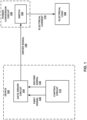
- FIG. 1 is a conceptual block diagram of a device 100 configured to cause a switch 162 of a power-conversion circuit 160 to deliver an electrical current 170 to an electrical load 180, in accordance with some examples of this disclosure.
- Device 100 includes control circuit 110 and gate driver circuit 140. Although device 100 is shown separate from power-conversion circuit 160 and electrical load 180, device 100 can be integrated with power-conversion circuit 160 and/or electrical load 180 into a single device. The techniques of this disclosure also apply where control circuit 110 and gate driver circuit 140 are discrete components on separate chips.
- Control circuit 110 is configured to generate signals 120 and 130 to encode information about electrical current 170. Control circuit 110 is able to control characteristics (e.g., parameters) of driver signal 150 by encoding information in signals 120 and 130 and delivering signals 120 and 130 to gate driver circuit 140. In the example of sinusoidal control mode, switch 162 delivers electrical current 170 having a sinusoidal shape to electrical load 180. Control circuit 110 may be configured to generate signals 120 and 130 as pulse-modulated signals (e.g., pulse-width modulated (PWM) signals). Control circuit 110 can modify the duty cycle, frequency, phase shift, the presence or absence of pulses, and/or other characteristics of signals 120 and 130 to encode the information about electrical current 170.
- PWM pulse-width modulated
- Control circuit 110 may be configured to determine a duty cycle of first signal 120 to encode the amplitude of the sinusoidal shape of electrical current 170.
- the shape of electrical current 170 is not necessarily exactly sinusoidal because electrical current 170 may include fluctuations, distortions, and ripples.
- the duty cycle of first signal 120 is defined as the percentage of time that first signal 120 has a high amplitude.
- Control circuit may determine the duty cycle (Duty_cycle 1 ) of first signal 120 as a function of the target amplitude (I M ) of electrical current 170 and the predetermined maximum amplitude (I MAX ) of the sinusoidal shape using Equation (1).
- Amplitudes 526 and 528 shown in FIG. 5 are examples of a target amplitude and a predetermined maximum amplitude, respectively.
- Duty _ cycle 1 I M I MAX
- Control circuit 110 may be configured to determine a duty cycle of second signal 130 to encode the phase angle of electrical current 170.
- the phase angle is the instantaneous phase angle of electrical current 170 at an associated moment in time. As one will understand, the value of the phase angle varies over time (see, e.g., phase angle 532).
- the phase angle indicates a point along the sinusoidal curve of electrical current 170 in terms of degrees or radians.
- the duty cycle of second signal 130 may represent a ratio between the phase angle of electrical current 170 and a predetermined angle value, such as 90 degrees ( ⁇ / 2 radians), 180 degrees ( ⁇ radians), or 360 degrees (2 ⁇ radians).
- Gate driver circuit 140 may then be configured to determine a factor based on a trigonometric function (e.g., a sinusoidal function, a cosine function, etc.). For instance, the phase angle is used, e.g., by gate driver circuit 140, as the input of the trigonometric function for determining the factor.
- the factor advantageously has a positive or null value.
- the factor is determined using one of Equations (4a) and (4b), where "A", "a", and “b” are parameters, and where "A" and "a” advantageously have non-null values.
- Equations (4a) and (4b) "A" is an amplitude of the respective trigonometric function.
- ⁇ t ⁇ rget is advantageously then comprised between 0 and 180 degrees.
- Circuits 110 and 140 are not limited to using a trigonometric function, e.g., that of Equations (4a) and (4b), for electrical current 170. In some examples, circuits 110 and 140 instead use an approximation of a trigonometric function for the determination of the factor, such as a polynomial approximation, an example of which is shown in Equation (4c), or a trigonometric transformation.
- control circuit 110 may be configured to encode other information in the characteristics of signals 120 and 130.
- control circuit 110 may be configured to encode the frequency of driver signal 150 in a frequency of first signal 120 or in a frequency of second signal 130.
- first signal 120 has a different respective frequency than second signal 130 (see, e.g., FIG. 6B ).
- the frequency of driver signal 150 may also be a fraction (N ⁇ 1) or a multiple (N > 1) of the frequency of the corresponding one of signals 120 and 130 (Frequencyi), as shown in Equation (6b).
- Frequency 1 N ⁇
- Frequency driver 1 N ⁇ Frequency 1
- gate driver circuit 140 can determine the frequency of driver signal 150 from the frequency of first signal 120 (or from the frequency of second signal 130).
- first signal 120 and/or second signal 130 has a frequency that is N times a frequency of driver signal 150, where N is an integer greater than or equal to two. Using a higher frequency for signal 120 and/or signal 130 allows for the encoding of more information per cycle of driver signal 150.
- Control circuit 110 may encode side information in one or both of signals 120 and 130.
- the side information may be transparent relative to the signal that encodes the side information, so that control circuit 110 and gate driver circuit 140 can determine the side information from the signal.
- the side information can be a rate of acceleration, a direction of rotation, specific fault blanking, recirculation high side or low side, fault reset/clear, fault comparator threshold change, active/diode freewheeling, and/or a command such as a brake command for a rotor in electrical load 180.
- Control circuit 110 may encode the side information in the frequency or one or both of signals 120 and 130 and/or a subinterval of cycles of one or both of signals 120 and 130 (e.g., FIG. 6B ).
- Control circuit 110 can also encode side information in a phase shift between signals 120 and 130.
- First signal 120 may be phase-shifted relative to second signal 130 if the active edges (e.g., rising edges and/or falling edges) of signals 120 and 130 are not always aligned in time. For example, if the frequency of first signal 120 is equal to the frequency of second signal 130, and there is no phase shift between signals 120 and 130, the rising edge of first signal 120 may be aligned in time with the rising edge of second signal 130 for each period (see, e.g., FIG. 6A ).
- Equation (7) shows an example for determining a phase shift as a fraction with the numerator set to a time difference in active edges and the denominator set to the time period of signals 120 and 130 (e.g., the inverse of the frequencies of signals 120 and 130).
- t active_130 and t active_120 correspond to the respective instants in time at which a given cycle of the signal 130 and a corresponding cycle of the signal 120 begin or end.
- the duty cycle of signals 120 and 130 may not affect the phase shift because the phase shift equals the delay between the beginning times of signals 120 and 130 or the delay between the end times of signals 120 and 130.
- phase shift t active _ 120 ⁇ t active _ 130 t period
- control circuit 110 encodes the phase angle of electrical current 170 in the phase shifts between signals 120 and 130.
- Gate driver circuit 140 can determine the phase shift between signals 120 and 130 by determining the time delay between the active edges of signals 120 and 130 and using Equation (7).
- Gate driver circuit 140 can determine the phase angle ( ⁇ target ) of electrical current 170 based on the determined phase shift and a predetermined angle value ( ⁇ predet. ), as shown in Equation (8).
- ⁇ target Phase shift ⁇ ⁇ predet .
- Gate driver circuit 140 is configured to deliver driver signal 150 to switch 162. Gate driver circuit 140 may be able to turn on and turn off switch 162 by controlling the voltage of driver signal 150.
- Driver signal 150 may be a pulse-modulated signal, such as a PWM signal, a pulse-density-modulated signal, and/or a pulse-frequency-modulated signal.
- Gate driver circuit 140 may deliver driver signal 150 to a control terminal of switch 162.
- Power-conversion circuit 160 includes switch 162.
- power-conversion circuit 160 includes more than one switch, such as a half-bridge circuit with two switches or a three-phase power-conversion circuit with six switches, where each phase includes a half-bridge circuit.
- Gate driver circuit 140 may deliver a driver signal to the control terminal of each switch of power-conversion circuit 160.
- Power-conversion circuit 160 may include a half-bridge circuit, an H-bridge circuit, a multi-phase conversion circuit, a buck conversion circuit, a boost conversion circuit, a buck-boost conversion circuit, a forward conversion circuit, a resonant-mode conversion circuit, and/or any other power conversion circuit.
- Switch 162 may be a power switch such as, but not limited to, any type of field-effect transistor (FET), a bipolar junction transistor (BJT), an insulated-gate bipolar transistor (IGBT), a high-electron-mobility transistor (HEMT), a gallium-nitride (GaN) based transistor, or another element that uses voltage for its control.
- Switch 162 may include an n-type transistor or a p-type transistor, and switch 162 may be a power transistor.
- switch 162 may be a vertical transistor, a lateral transistor, and/or a horizontal transistor.
- switch 162 may include another analog device such as a diode and/or a thyristor.
- Switch 162 may also include a freewheeling diode connected in parallel with a transistor to prevent reverse breakdown of switch 162.
- Switch 162 may include three terminals: two load terminals and a control terminal.
- switch 162 may include a drain terminal, a source terminal, and at least one gate terminal, where the control terminal is a gate terminal.
- control terminals may be base terminals. Electrical current 170 may flow between the load terminals of switch 162, based on the voltage at the control terminal, to electrical load 180.
- Switch 162 may include various material compounds, such as silicon (Si), silicon carbide (SiC), Gallium Nitride (GaN), or any other combination of one or more semiconductor materials.
- silicon Si
- SiC silicon carbide
- GaN Gallium Nitride
- power converters may operate at higher frequencies.
- silicon carbide switches may experience lower switching power losses. Improvements in magnetics and faster switching, such as Gallium Nitride switches, may support higher frequency converters. These higher frequency circuits may require control signals to be sent with more precise timing, as compared to lower-frequency circuits.
- Electrical load 180 may include an electric motor, an electrical circuit, an electronic device, a light-producing device, a sound-producing device, and/or any other electrical load.
- electrical load 180 is an electric motor including windings configured to receive electrical current 170.
- Electrical load 180 may also include a rotor, where control circuit 110 is configured to control the speed, rate of acceleration, and direction of rotation of the rotor.
- Electrical load 180 may include a sensor or sensing circuit configured to deliver a sense signal to device 100, where the sense signal indicates the operation of electrical load 180, the amount of electrical current 170 delivered to electrical load 180, and/or the back EMF at electrical load 170.
- electrical load 180 is a multi-phase electric motor including a winding for each phase. Each winding receives an electrical current from power-conversion circuit 160 and generates a magnetic field based on the electrical current. Each electrical current generated by power-conversion circuit 160 may have a sinusoidal shape with a frequency that is equal to the frequency of the rotation of the rotor of electrical load 180. The frequency of driver signal 150 may be much greater than the frequency of the electrical currents. Driver signal 150 may drive the switches of power-conversion circuit 160 to deliver the electrical currents to electrical load 180. In the example of an N-phase electric motor driver, gate driver circuit 140 may deliver N, 2N, or 4N driver signals to the switches of power-conversion circuit 160 to cause the switches to deliver N electrical currents to electrical load 180.
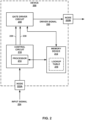
- FIG. 2 is a conceptual block diagram of a device 200 including a processor 214 and a memory device 212, in accordance with some examples of this disclosure.
- Memory device 212 is configured to store data relating to the operation of processor 214 and gate driver circuit 240.
- Memory device 212 may store data indicating a predetermined maximum amplitude for an electrical current, a predetermined angle value for a trigonometric function, a predetermined amount for an offset for two or more electrical currents. For a three-phase electrical load, the predetermined amount may be 120 degrees between each of the three electrical currents.
- Memory device 212 may include optional lookup table 216 configured to store input values and output values for a trigonometric function or an approximation thereof, e.g., that of Equations (4a)-(4c).
- Processor 214 and/or gate driver circuit 240 may be configured to provide to memory device 212 an address corresponding to the input value for the trigonometric function.
- gate driver circuit 240 may determine the phase angle from second signal 230 and use the phase angle as an input value for the trigonometric function stored to memory device 212 and/or lookup table 216.
- memory device 212 may store a factor between zero and one. For example, at an address for the phase angle of thirty degrees, memory device 212 may store a factor of 0.5.
- Lookup table 216 is only one example of a means for processor 214 and/or gate driver circuit 240 to determine a factor and/or a duty cycle for driver signal 250. There are other means for implementing a trigonometric function or an approximation of a trigonometric function.
- processor 214 and/or gate driver circuit 240 can use a mixture of a lookup table and an approximation, such as a linear approximation, a trigonometric approximation, a Taylor series approximation, a polynomial approximation, and/or any other approximation.
- Processor 214 and/or gate driver circuit 240 can use any of the listed approximations to approximate the trigonometric function.
- processor 214 and/or gate driver circuit 240 can use an algorithm, such as a coordinate rotation digital computer (Cordic) algorithm or a known complex algorithm.
- Cordic coordinate rotation digital computer
- Processor 214 may include any combination of integrated circuitry, discrete logic circuity, analog circuitry, such as one or more microcontrollers, one or more microprocessors, DSPs, application specific integrated circuits (ASICs), and/or field-programmable gate arrays (FPGAs).
- processor refers one or more processors distributed across one or more devices.
- processor can include a single processor or multiple processors on a device.
- processor can also include processors on multiple devices, where the operations described herein may be distributed across multiple processors and/or multiple devices.
- Processor 214 may be configured to determine a target amplitude and a target phase angle of the electrical current based on input signal 224 received at node 222A. Processor 214 may use these target values to determine the characteristics of signals 220 and 230.
- Input signal 224 may be a sense signal indicating the operation of an electrical load and/or the electrical current delivered by a switch to the electrical load. Input signal 224 may originate from a Hall sensor placed near the electrical load (e.g., near a rotor). Input signal 224 may also originate from the back EMF (BEMF) in the example of sensorless control.
- BEMF back EMF
- gate driver circuit 240 includes a Hall sensor or a BEMF sensor. Therefore, gate driver circuit 240 can autonomously define synchronization of the phases without intervention from processor 214, which simplifies the feedback loop shown in FIG. 2 by possibly removing the need for control circuit 210.
- Nodes 222A and 222B may include pins, leads, leadframe segments, metallization layers, and/or any other suitable conductive nodes for receiving input signal 224 and outputting driver signal 250.
- Nodes 222A and 222B can be positioned on the surface or on the housing of device 200.
- FIG. 3 is a conceptual block diagram of a device 300 including an oscillator 312 and an operational amplifier 316, in accordance with some examples of this disclosure.
- Oscillator 312 may be a voltage-controlled oscillator (VCO) configured to output a clock signal for integrator 314.
- Operational amplifier 316 may generate a triangle waveform or a sawtooth waveform based on the clock signal.
- Comparator 318 may be configured to generate signals 320 and 330 by comparing the triangle waveform or the sawtooth waveform to a reference signal.
- the reference signal may be input signal 324 or a signal determined as a function of input signal 324.
- FIGS. 4A-4C illustrate the sinusoidal control technique for determining the duty cycle for a driver signal 420.
- the duty cycle of driver signal 420 is based on the percentage time that an amplitude of sinusoidal carrier waveform 400 is greater than an amplitude of triangular waveform 410.
- a gate driver circuit can generate driver signal 420 by using sinusoidal carrier waveform 400 and triangular waveform 410 at the desired driver frequency.
- the frequency of triangular waveform 410 is the same as the frequency of driver signal 420.
- a gate driver circuit may include a comparator that receives sinusoidal carrier waveform 400 and triangular waveform 410 as input signals and generates driver signal 420 as an output signal. For example, when the amplitude of sinusoidal carrier waveform 400 is greater than the average amplitude of triangular waveform 410, e.g., in region 430, the gate driver circuit may generate driver signal 420 with a duty cycle greater than fifty percent. When the amplitude of sinusoidal carrier waveform 400 is less than the average amplitude of triangular waveform 410, e.g., in region 440, the gate driver circuit may generate driver signal 420 with a duty cycle less than fifty percent.
- FIG. 5 illustrates further details of the sinusoidal control technique for determining characteristics of an electrical current 570, in accordance with some examples of this disclosure.
- FIG. 5 shows signals 520 and 530, which may be generated by control circuit 110 and received by gate driver circuit 140 of FIG. 1 .
- Signals 520 and 530 are examples of signals 120 and 130 shown in FIG. 1 , signals 220 and 230 shown in FIG. 2 , and signals 320 and 330 shown in FIG. 3 .
- FIGS. 5 and 6 are described with respect to device 100 of FIG. 1 , devices 200 and 300 of FIGS. 2 and 3 may perform similar techniques.
- control circuit 110 may generate signal 520 to encode amplitude 526 (I M ) of electrical current 570.
- the duty cycle of signal 520 is equal to the duration of the high pulse of signal 520 (duration 522) divided by the duration of a period of signal 520 (duration 524).
- a duty cycle of one hundred percent for signal 520 could encode an amplitude that is equal to predetermined maximum amplitude 528 at a phase angle of 90 degrees.
- Control circuit 110 may use Equation (1) to determine the duty cycle of signal 520, and gate driver circuit 140 can use Equation (5) to determine the duty cycle of driver signal 150 based on the duty cycle of signal 520.
- Control circuit 110 may generate signal 530 to encode phase angle 532 of electrical current 570.
- the duty cycle of signal 530 is equal to the duration of the high pulse of signal 530 divided by the duration of a period of signal 530 (duration 582). In the example of FIG. 5 , duration 582 is equal to duration 524, but in some examples the frequency of signal 520 is not the same as the frequency of signal 530 (see, e.g., FIG. 6B ).
- a duty cycle of one hundred percent for signal 530 could encode a phase angle that is equal to predetermined angle value 534, shown in FIG 5 as 180 degrees.
- Control circuit 110 may use Equation (2) to determine phase angle 532 of signal 530, and gate driver circuit 140 can use Equation (3) to determine phase angle 532 based on the duty cycle of signal 530.
- control circuit 110 may increase the duty cycle of signal 530 by 8.33% for each period of signal 530 before resetting the duty cycle to zero at the end of duration 580.
- gate driver circuit 140 may increase phase angle 532 by fifteen degrees for each period of signal 530 before resetting phase angle 532 to zero at the end of duration 580.
- Predetermined angle value 534 is equal to 180 degrees in the example of FIG. 5 , but predetermined angle value 534 may have other values, such as 90 degrees or 360 degrees.
- phase angle 532 will not represent the full 360 degrees of the sinusoidal shape of electrical current 570, but gate driver circuit 140 can complete the sinusoidal shape using tracking, extrapolation, and/or any other suitable technique.
- Gate driver circuit 140 can determine a numerical value of a factor by inputting phase angle 532 into a trigonometric function or an approximation thereof, as shown in Equations (4a)-(4c). Gate driver circuit 140 can determine the duty cycle of driver signal 150 by multiplying the factor and the duty cycle of signal 520, as shown in Equation (5). Gate driver circuit 140 may read the factor value from a memory device, which may store an array or a lookup table including the numerical values of the factor and associated values of phase angle 532. The duty cycle of driver signal 150 may be approximately equal to the duty cycle of the voltage level at a phase node of power-conversion circuit 160.
- gate driver circuit 140 determines the duty cycles of all of the driver signals based on Equations (1)-(5) and predetermined amounts for the offsets between the three phases. Gate driver circuit 140 may use these techniques to determine the duty cycles of driver signal 150 for negative values of electrical current 170. This technique for determining duty cycles reduces the amount of memory that is needed to store data for the trigonometric function.
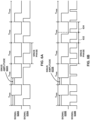
- FIGS. 6A and 6B illustrate two signals that encode amplitude and a phase angle of an electrical current, in accordance with some examples of this disclosure.
- Signals 620A and 630A shown in FIG. 6A and signals 620B and 630B shown in FIG. 6B are examples of signals 120 and 130 shown in FIG. 1 , signals 220 and 230 shown in FIG. 2 , signals 320 and 330 shown in FIG. 3 , and signals 520 and 530 shown in FIG. 5 .
- signal 620A has the same frequency as signal 630A, equal to the inverse of T PWM
- signal 630B has a frequency that is two times the frequency of signal 620B.
- the duty cycles of signals 620A and 620B encode the amplitude of electrical currents.
- gate driver circuit 140 can determine the duty cycle of signals 620A and 620B by dividing durations 622A and 622B by the period T PWM .
- Gate driver circuit 140 may determine the amplitude of electrical current 170 to be proportional to the duty cycle of the duty cycle of signal 620A or 620B using Equation (1).
- FIG. 6A shows an example where a phase angle of electrical current 170 is encoded in the duty cycle of signal 630A across a full period T PWM .
- FIG. 6B shows an example where the frequency of signal 630B is twice the frequency of signal 620B.
- signal 630B includes two subintervals (e.g., time periods) for each T PWM period or cycle of signal 620B.
- subinterval 632 may encode the phase angle of electrical current 170
- subinterval 634 may encode side information, such as acceleration, direction of rotation, and/or other commands.
- the presence or absence of one or more pulses in subinterval 632 or 634 may encode the side information.
- FIG. 6B depicts the presence of one pulse in each of subintervals 632 or 634, a subinterval of signal 630B may have zero, one, two, or any number of pulses.
- Control circuit 110 may generate signal 630B to encode side information in the number of pulses in a subinterval.
- Control circuit 110 can also generate signal 630B to encode information in the duty cycle of subinterval 632 and to define a phase shift between signals 620B and 630B in subinterval 634. For example, if subinterval 632 includes a pulse but subinterval 634 has no pulse, then gate driver circuit 140 operates in a first state or control mode.
- gate driver circuit 140 detects pulses in both of subintervals 632 and 634, gate driver circuit 634 operates in a second state or control mode based on the additional command.
- signal 630B includes the phase angle information, for example, as the total pulse width over one PWM period (T PWM ).
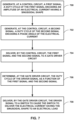
- FIGS. 7-9B are flow diagrams illustrating example techniques for causing a switch to deliver an electrical current to an electrical load, in accordance with some examples of this disclosure.
- the techniques of FIGS. 7-9B are described with reference to device 100 in FIG. 1 , although other components, such as devices 200 and 300 in FIGS. 2 and 3 , may exemplify similar techniques.
- the technique of FIG. 7 includes control circuit 110 generating first signal 120, where a duty cycle of first signal 120 encodes an amplitude of electrical current 170 having a sinusoidal shape (700). Control circuit 110 can encode the amplitude of electrical current 170 in the duty cycle of signal 120 as a function of a predetermined maximum amplitude using Equation (1).
- the technique of FIG. 7 also includes control circuit 110 generating second signal 130, where a duty cycle of second signal 130 encodes a phase angle of electrical current 170 (702). Control circuit 110 can encode the phase angle of electrical current 170 as a function of a predetermined angle value using Equation (2). Control circuit 110 then delivers signals 120 and 130 to gate driver circuit 140 (704).
- the technique of FIG. 7 also includes gate driver circuit 140 receiving signals 120 and 130 and determining a duty cycle of driver signal 150 as a function of signals 120 and 130 (706).
- Driver signal 150 can be a pulse-modulated signal (e.g., a square waveform).
- Gate driver circuit 140 can determine the duty cycle of driver signal 150 based on the duty cycles of signals 120 and 130 using Equations (3)-(5).
- the technique of FIG. 7 includes gate driver circuit 140 delivering driver signal 150 to switch 162 to cause switch 162 to deliver electrical current 170 having the sinusoidal shape to electrical load 180 (708).
- FIG. 8 depicts a technique for encoding the phase angle in the phase shift between signals 120 and 130.
- the technique of FIG. 8 includes control circuit 110 generating signals 120 and 130, such that a duty cycle of first signal 120 encodes an amplitude of electrical current 170 having a sinusoidal shape (800).
- a duty cycle of second signal 130 encodes information, first signal 120 being phase-shifted relative to second signal 130 by a phase shift encoding a phase angle of electrical current 170 (802).
- Control circuit 110 then delivers signals 120 and 130 to gate driver circuit 140 (804).
- control circuit 110 can encode other information in the duty cycle of second signal 130.
- control circuit can encode the frequency, a rate of acceleration, a direction of rotation, and/or commands such as a braking command.
- Control circuit 110 may encode the phase angle of electrical current 170 in the phase shift between signals 120 and 130 as a numerical value between one and zero.
- the phase shift may represent a ratio between the phase angle of electrical current 170 and a predetermined angle value. For example, if the rising edges of signals 120 and 130 are aligned in time, gate driver circuit 140 may determine that the phase angle of electrical current 170 is zero. If the rising edge of second signal 130 is phase-shifted in time from the rising edge of first signal 120 by half of a period of signals 120 and 130, then gate driver circuit 140 may determine that the phase angle of electrical current 170 is equal to half of the predetermined angle value.
- the technique of FIG. 8 includes gate driver circuit 140 determining a duty cycle of driver signal 150 as a function of signals 120 and 130 (806). Gate driver circuit 140 can determine the phase shift between signals 120 and 130 using Equation (7). Gate driver circuit 140 can determine the phase angle of electrical current 170 based on the phase shift using Equation (8). Gate driver circuit 140 can then determine the duty cycle of driver signal 150 based on the determined phase angle of electrical current 170 using one of Equations (4a)-(4c) and Equation (5). Gate driver circuit 140 may continually re-determine the duty cycle of driver signal 150 for each new cycle or period of signals 120 and 130.
- gate driver circuit 140 can re-determine the duty cycle of driver signal 150 at a slower rate, such as every two, three, or any number of periods of duty cycle of driver signal 150. Gate driver circuit 140 then delivers driver signal 150 to switch 162 to cause switch 162 to deliver electrical current 170 having the sinusoidal shape to electrical load 180 (808).
- FIGS. 9A and 9B depict the example operations of control circuit 110 and gate driver circuit 140.
- the technique of FIG. 9A includes control circuit 110 generating first signal 120, where a duty cycle of first signal 120 encodes an amplitude of electrical current 170 having a sinusoidal shape (900). Control circuit 110 can encode the amplitude of electrical current 170 in the duty cycle of signal 120 as a function of a predetermined maximum amplitude using Equation (1).
- the technique of FIG. 9A also includes control circuit 110 generating second signal 130, where a duty cycle of second signal 130 encodes a phase angle of electrical current 170 (902).
- Control circuit 110 can encode the phase angle of electrical current 170 as a function of a predetermined angle value using Equation (2). Control circuit 110 then delivers signals 120 and 130 to gate driver circuit 140 (904).
- the technique of FIG. 9B includes gate driver circuit 140 receiving signals 120 and 130 (905) and determining a duty cycle of driver signal 150 as a function of signals 120 and 130 (906). Gate driver circuit 140 can determine the duty cycle of driver signal 150 based on the duty cycles of signals 120 and 130 using Equations (3)-(5). The technique of FIG. 9B includes gate driver circuit 140 delivering driver signal 150 to switch 162 to cause switch 162 to deliver electrical current 170 having the sinusoidal shape to electrical load 180 (908).
- Control circuits 110 and 210 may include one or more processors, such as processor 214.
- Control circuits 110 and 210 may include any combination of integrated circuitry, discrete logic circuity, analog circuitry, such as one or more microprocessors, DSPs, ASICs, or FPGAs.
- control circuits 110 and 210 may include multiple components, such as any combination of one or more microprocessors, one or more DSPs, one or more ASICs, or one or more FPGAs, as well as other discrete or integrated logic circuitry, and/or analog circuitry.
- non-transitory computer-readable storage media may include RAM, ROM, programmable ROM (PROM), erasable programmable ROM (EPROM), electronically erasable programmable ROM (EEPROM), flash memory, a hard disk, a compact disc ROM (CD-ROM), a floppy disk, a cassette, magnetic media, optical media, or any other computer readable storage devices or tangible computer readable media.
- non-transitory may indicate that the storage medium is not embodied in a carrier wave or a propagated signal.
- a non-transitory storage medium may store data that can, over time, change (e.g., in RAM or cache).
Landscapes
- Engineering & Computer Science (AREA)
- Power Engineering (AREA)
- Inverter Devices (AREA)
- Control Of Motors That Do Not Use Commutators (AREA)
Claims (10)
- System, das aufweist:eine Leistungswandlungschaltung mit einem Schalter (162); undeine Anordnung, die aufweist:eine Gate-Treiberschaltung (140; 240; 340); undeine Steuerschaltung (110; 210; 310) die dazu ausgebildet ist:ein erstes Signal (120; 220; 320) zu erzeugen, wobei ein Tastverhältnis des ersten Signals (120; 220; 320) eine Amplitude eines elektrischen Stroms (170), der eine Sinusform hat, zu kodieren,ein zweites Signal (130; 230; 330) zu erzeugen, das einen Phasenwinkel des elektrischen Stroms (170) kodiert, unddas erste Signal (120; 220; 320) und das zweite Signal (130; 230; 330) an die Gate-Treiberschaltung (140; 240; 340) zu liefern,wobei die Gate-Treiberschaltung (140; 240; 340) dazu ausgebildet ist:ein Tastverhältnis eines Treibersignals (150; 250; 350) als eine Funktion des ersten Signals (120; 220; 320) und des zweiten Signals (130; 230; 330) zu ermitteln, unddas Treibersignal (150; 250; 350) an den Schalter (162) der Leistungswandlungsschaltung (160) zu liefern, was die Leistungswandlungsschaltung (160) dazu veranlasst, den elektrischen Strom (170, der die Sinusform hat, an eine elektrische Last (180) zu liefern,wobei ein Tastverhältnis des zweiten Signals (130; 230; 330) den Phasenwinkel des elektrischen Stroms (170) kodiert,wobei das Tastverhältnis des ersten Signals (120; 220; 320) repräsentativ ist für ein Verhältnis zwischen der Amplitude des elektrischen Stroms (170) und einer vorgegebenen maximalen Amplitude,wobei das Tastverhältnis des zweiten Signals (130; 230; 330) repräsentativ ist für ein Verhältnis zwischen dem Phasenwinkel des elektrischen Stroms (170) und einem vorgegebenen Winkelwert,wobei die Gate-Treiberschaltung (150; 250; 350) weiterhin dazu ausgebildet ist:basierend auf dem Tastverhältnis des zweiten Signals (130; 230; 330) einen Faktor zu ermitteln, wobei ein numerischer Wert des Faktors zwischen null und eins liegt, unddas Tastverhältnis des Treibersignals (150; 250; 350) als ein Ergebnis einer Multiplikation des Tastverhältnisses des ersten Signals und des Faktors zu ermitteln, undwobei die Gate-Treiberschaltung (150; 250; 350) dazu ausgebildet ist, den Faktor zu ermitteln wenigstens durch:Ermitteln des Phasenwinkels des elektrischen Stroms (170) basierend auf dem Tastverhältnis des zweiten Signals (130; 230; 330) und dem vorgegebenen Winkelwert, undErmitteln, unter Verwendung einer trigonometrischen Funktion oder deren Annäherung, des Faktors als Ausgabewert der trigonometrischen Funktion oder von deren Annäherung unter Verwendung des Phasenwinkels des elektrischen Stroms (170) als Eingabewert der trigonometrischen Funktion oder von deren Annäherung.
- System gemäß Anspruch 1, wobei eine Frequenz des Treibersignals (150; 250; 350) als Frequenz des ersten Signals (120; 220; 320) oder als Frequenz des zweiten Signals (130; 230; 330) kodiert ist
- System gemäß Anspruch 1 oder 2, wobei das erste Signal (120; 220; 320) und das zweite Signal (130; 230; 330) jeweils unterschiedliche Frequenzen haben.
- System gemäß einem der Ansprüche 1 bis 3, wobei das Treibersignal (150; 250; 350) ein pulsweitenmoduliertes (PWM) Signal ist und wobei wenigstens eines von dem ersten Signal (130; 230; 330) oder dem zweiten Signal (130; 230; 330) eine Frequenz hat, die das N-fache einer Frequenz des PWM-Signals ist, wobei N eine ganze Zahl größer oder gleich zwei ist.
- Vorrichtung gemäß einem der Ansprüche 1 bis 4,wobei das Treibersignal (150; 250; 350) ein erstes Treibersignal von drei Treibersignalen ist, die außerdem ein zweites Treibersignal und ein drittes Treibersignal umfassen,wobei der Schalter (162) ein erster Schalter von mehreren Schaltern ist, die drei Schalter umfassen,wobei der elektrische Strom (170) ein erster elektrischer Strom von drei elektrischen Strömen ist, die außerdem einen zweiten elektrischen Strom und einen dritten elektrischen Strom umfassen, undwobei die Gate-Treiberschaltung (140; 240; 340) weiterhin dazu ausgebildet ist:ein jeweiliges Tastverhältnis der drei Treibersignale als Funktion des ersten Signals und des zweiten Signals zu ermitteln, unddie drei Treibersignale an die drei Schalter zu liefern, um die drei Schalter zu veranlassen, drei jeweilige elektrische Ströme an die elektrische Last zu liefern, die jeweils eine Sinusform haben, wobei die drei elektrischen Ströme jeweilige Phasenwinkel haben, die um einen vorgegebenen Wert zueinander verschoben sind.
- System nach Anspruch 5, wobei die Gate-Treiberschaltung (140; 240; 340) dazu ausgebildet ist:ein Tastverhältnis des zweiten Treibersignal basierend auf dem ersten Signal, dem zweiten Signal und einem jeweiligen vorgegebenen Wert, um den der zweite elektrische Strom relativ zu dem ersten elektrischen Strom verschoben ist, zu ermitteln, undein Tastverhältnis des dritten Treibersignals basierend auf dem ersten Signal, dem zweiten Signal und einem jeweiligen vorgegebenen Wert, um den der dritte elektrische Strom relativ zu dem ersten elektrischen Strom verschoben ist, zu ermitteln.
- System gemäß einem der Ansprüche 1 bis 5, wobei wenigstens eines von dem ersten Signal (120; 220; 320) oder dem zweiten Signal (130; 230; 330) eine Nebeninformation für die Gate-Treiberschaltung (140; 240; 340) zusätzlich zu dem Phasenwinkel des elektrischen Stroms (170) und der Amplitude des elektrischen Stroms (170) kodiert.
- System gemäß Anspruch 7, wobei die Nebeninformation kodiert wird unter Verwendung eines Vorhandenseins oder eines Nicht-Vorhandenseins eines oder mehrerer Impulse, die in einem Unterintervall von Zyklen des wenigstens einen von dem ersten Signal (120; 220; 320) oder dem zweiten Signal (130; 230; 330) angeordnet sind.
- System gemäß Anspruch 7, wobei das erste Signal (120; 220; 320) relativ zu dem zweiten Signal um eine Phasenverschiebung phasenverschoben ist und wobei die Phasenverschiebung die Nebeninformation für die Gate-Treiberschaltung kodiert.
- System gemäß Anspruch 7, wobei die elektrische Last (180) einen elektrischen Motor mit einem Rotor umfasst, und wobei die Nebeninformation eine Rotationsrichtung für den Rotor definiert und die Gate-Treiberschaltung dazu veranlasst, das Treibersignal an den Schalter zu liefern, um den Schalter zu veranlassen, den Rotor so anzusteuern, dass er in der durch die Nebeninformation definierten Rotationsrichtung rotiert.
Applications Claiming Priority (1)
| Application Number | Priority Date | Filing Date | Title |
|---|---|---|---|
| US15/988,509 US10693454B2 (en) | 2018-05-24 | 2018-05-24 | Signals for the control of power devices |
Publications (2)
| Publication Number | Publication Date |
|---|---|
| EP3573234A1 EP3573234A1 (de) | 2019-11-27 |
| EP3573234B1 true EP3573234B1 (de) | 2023-11-01 |
Family
ID=66630220
Family Applications (1)
| Application Number | Title | Priority Date | Filing Date |
|---|---|---|---|
| EP19175898.6A Active EP3573234B1 (de) | 2018-05-24 | 2019-05-22 | System für die steuerung von leistungsvorrichtungen |
Country Status (3)
| Country | Link |
|---|---|
| US (1) | US10693454B2 (de) |
| EP (1) | EP3573234B1 (de) |
| CN (1) | CN110535331B (de) |
Families Citing this family (4)
| Publication number | Priority date | Publication date | Assignee | Title |
|---|---|---|---|---|
| US11378997B2 (en) * | 2018-10-12 | 2022-07-05 | Ultrahaptics Ip Ltd | Variable phase and frequency pulse-width modulation technique |
| EP3739755B1 (de) | 2019-05-16 | 2025-07-02 | Solaredge Technologies Ltd. | Gate-treiber für zuverlässiges schalten |
| US12587193B2 (en) * | 2019-11-26 | 2026-03-24 | Eaton Intelligent Power Limited | Proximity sensor with integrated control features and method of operation thereof |
| ES2998334T3 (en) * | 2021-04-23 | 2025-02-19 | Contemporary Amperex Technology Hong Kong Ltd | Converter control method and apparatus, and readable storage medium |
Family Cites Families (8)
| Publication number | Priority date | Publication date | Assignee | Title |
|---|---|---|---|---|
| US6111680A (en) * | 1997-12-01 | 2000-08-29 | Ebara Corporation | Transmitting a signal using duty cycle modulation |
| US7456600B1 (en) * | 2008-06-24 | 2008-11-25 | System Homes Company, Ltd. | Pulse code width modulation motor drive system |
| JP2015050909A (ja) * | 2013-09-04 | 2015-03-16 | オムロンオートモーティブエレクトロニクス株式会社 | モータ制御装置 |
| US9980332B2 (en) * | 2014-02-14 | 2018-05-22 | Philips Lighting Holdings B.V. | Circuit and method for controlling pulse width modulation of a current supply for a load |
| RU2707876C2 (ru) * | 2014-11-11 | 2019-12-02 | Филипс Лайтинг Холдинг Б.В. | Возбуждение осветительного элемента |
| US10170905B2 (en) * | 2016-04-08 | 2019-01-01 | Infineon Technologies Ag | Electronic switching and protection circuit with wakeup function |
| CN105978303B (zh) * | 2016-06-29 | 2018-09-25 | 成都芯源系统有限公司 | 恒定导通时间控制的开关变换器及其自动校准方法 |
| CN106411291B (zh) * | 2016-07-31 | 2023-04-07 | 华南理工大学 | 一种阶数大于1的大功率可调高频分数阶电容及其控制方法 |
-
2018
- 2018-05-24 US US15/988,509 patent/US10693454B2/en active Active
-
2019
- 2019-05-22 EP EP19175898.6A patent/EP3573234B1/de active Active
- 2019-05-23 CN CN201910435170.5A patent/CN110535331B/zh active Active
Also Published As
| Publication number | Publication date |
|---|---|
| US20190363709A1 (en) | 2019-11-28 |
| CN110535331A (zh) | 2019-12-03 |
| US10693454B2 (en) | 2020-06-23 |
| EP3573234A1 (de) | 2019-11-27 |
| CN110535331B (zh) | 2024-06-07 |
Similar Documents
| Publication | Publication Date | Title |
|---|---|---|
| EP3573234B1 (de) | System für die steuerung von leistungsvorrichtungen | |
| CN106817051B (zh) | 用于驱动无传感器bldc电机的设备和控制方法 | |
| US9531317B2 (en) | Power conversion apparatus, power conversion method, and motor system | |
| US8872457B2 (en) | Method and apparatus for driving a polyphase electronically commutated electric machine and a motor system | |
| CN108574434B (zh) | 集成电路 | |
| US20150023804A1 (en) | Driving device and driving method for motor, cooling device and electronic machine | |
| Pindoriya et al. | Analysis of position and speed control of sensorless BLDC motor using zero crossing back-EMF technique | |
| WO2013057853A1 (ja) | モータ駆動システムおよびその制御方法 | |
| JP6644159B2 (ja) | モータ駆動装置、電動送風機、電気掃除機及びハンドドライヤー | |
| EP3343758A1 (de) | Halbleiterbauelement und stromumwandlungsvorrichtung | |
| JP2019213367A (ja) | ブラシレスdcモータの制御方法及び制御装置 | |
| JP5300944B2 (ja) | 電力変換装置、冷凍空調装置および電力変換装置の制御方法 | |
| JP6004374B2 (ja) | モータ制御装置及びモータ制御方法 | |
| US9130486B2 (en) | Motor position detecting unit and brushless DC motor system | |
| US10097115B2 (en) | Auto-synchronization of brushless DC motors | |
| WO2002060047A1 (en) | Inverter apparatus | |
| CN101051805A (zh) | 用于调节电动机特性曲线的电路装置 | |
| Lim et al. | A new technique of reducing torque ripples for BDCM drives | |
| Lee et al. | Torque ripple minimization via PWM control technique with GaN-based motor drive for high speed single phase brushless DC motor | |
| US11146190B2 (en) | Multiphase synchronous motor controller with angle tracking | |
| Yadav et al. | Position and speed control of brushless DC motors using sensorless techniques: A review | |
| US11239760B2 (en) | Power conversion system and control method for voltage conversion circuit | |
| KR102238456B1 (ko) | 스위치드 릴럭턴스 모터를 구동하는 구동 회로 | |
| US20150180385A1 (en) | Driving signal generating apparatus, and system and method for driving motor using the same | |
| CN107787550B (zh) | 利用pwm信号控制电机的方法、装置以及机动车辆电机 |
Legal Events
| Date | Code | Title | Description |
|---|---|---|---|
| PUAI | Public reference made under article 153(3) epc to a published international application that has entered the european phase |
Free format text: ORIGINAL CODE: 0009012 |
|
| STAA | Information on the status of an ep patent application or granted ep patent |
Free format text: STATUS: THE APPLICATION HAS BEEN PUBLISHED |
|
| AK | Designated contracting states |
Kind code of ref document: A1 Designated state(s): AL AT BE BG CH CY CZ DE DK EE ES FI FR GB GR HR HU IE IS IT LI LT LU LV MC MK MT NL NO PL PT RO RS SE SI SK SM TR |
|
| AX | Request for extension of the european patent |
Extension state: BA ME |
|
| STAA | Information on the status of an ep patent application or granted ep patent |
Free format text: STATUS: REQUEST FOR EXAMINATION WAS MADE |
|
| 17P | Request for examination filed |
Effective date: 20200527 |
|
| RBV | Designated contracting states (corrected) |
Designated state(s): AL AT BE BG CH CY CZ DE DK EE ES FI FR GB GR HR HU IE IS IT LI LT LU LV MC MK MT NL NO PL PT RO RS SE SI SK SM TR |
|
| STAA | Information on the status of an ep patent application or granted ep patent |
Free format text: STATUS: EXAMINATION IS IN PROGRESS |
|
| 17Q | First examination report despatched |
Effective date: 20210722 |
|
| GRAP | Despatch of communication of intention to grant a patent |
Free format text: ORIGINAL CODE: EPIDOSNIGR1 |
|
| STAA | Information on the status of an ep patent application or granted ep patent |
Free format text: STATUS: GRANT OF PATENT IS INTENDED |
|
| INTG | Intention to grant announced |
Effective date: 20230320 |
|
| GRAS | Grant fee paid |
Free format text: ORIGINAL CODE: EPIDOSNIGR3 |
|
| GRAJ | Information related to disapproval of communication of intention to grant by the applicant or resumption of examination proceedings by the epo deleted |
Free format text: ORIGINAL CODE: EPIDOSDIGR1 |
|
| GRAL | Information related to payment of fee for publishing/printing deleted |
Free format text: ORIGINAL CODE: EPIDOSDIGR3 |
|
| STAA | Information on the status of an ep patent application or granted ep patent |
Free format text: STATUS: EXAMINATION IS IN PROGRESS |
|
| GRAP | Despatch of communication of intention to grant a patent |
Free format text: ORIGINAL CODE: EPIDOSNIGR1 |
|
| STAA | Information on the status of an ep patent application or granted ep patent |
Free format text: STATUS: GRANT OF PATENT IS INTENDED |
|
| INTC | Intention to grant announced (deleted) | ||
| INTG | Intention to grant announced |
Effective date: 20230720 |
|
| GRAA | (expected) grant |
Free format text: ORIGINAL CODE: 0009210 |
|
| STAA | Information on the status of an ep patent application or granted ep patent |
Free format text: STATUS: THE PATENT HAS BEEN GRANTED |
|
| AK | Designated contracting states |
Kind code of ref document: B1 Designated state(s): AL AT BE BG CH CY CZ DE DK EE ES FI FR GB GR HR HU IE IS IT LI LT LU LV MC MK MT NL NO PL PT RO RS SE SI SK SM TR |
|
| REG | Reference to a national code |
Ref country code: GB Ref legal event code: FG4D |
|
| P01 | Opt-out of the competence of the unified patent court (upc) registered |
Effective date: 20231010 |
|
| REG | Reference to a national code |
Ref country code: CH Ref legal event code: EP |
|
| REG | Reference to a national code |
Ref country code: DE Ref legal event code: R096 Ref document number: 602019040415 Country of ref document: DE |
|
| REG | Reference to a national code |
Ref country code: IE Ref legal event code: FG4D |
|
| REG | Reference to a national code |
Ref country code: LT Ref legal event code: MG9D |
|
| REG | Reference to a national code |
Ref country code: NL Ref legal event code: MP Effective date: 20231101 |
|
| PG25 | Lapsed in a contracting state [announced via postgrant information from national office to epo] |
Ref country code: GR Free format text: LAPSE BECAUSE OF FAILURE TO SUBMIT A TRANSLATION OF THE DESCRIPTION OR TO PAY THE FEE WITHIN THE PRESCRIBED TIME-LIMIT Effective date: 20240202 |
|
| PG25 | Lapsed in a contracting state [announced via postgrant information from national office to epo] |
Ref country code: IS Free format text: LAPSE BECAUSE OF FAILURE TO SUBMIT A TRANSLATION OF THE DESCRIPTION OR TO PAY THE FEE WITHIN THE PRESCRIBED TIME-LIMIT Effective date: 20240301 |
|
| PG25 | Lapsed in a contracting state [announced via postgrant information from national office to epo] |
Ref country code: LT Free format text: LAPSE BECAUSE OF FAILURE TO SUBMIT A TRANSLATION OF THE DESCRIPTION OR TO PAY THE FEE WITHIN THE PRESCRIBED TIME-LIMIT Effective date: 20231101 |
|
| REG | Reference to a national code |
Ref country code: AT Ref legal event code: MK05 Ref document number: 1628386 Country of ref document: AT Kind code of ref document: T Effective date: 20231101 |
|
| PG25 | Lapsed in a contracting state [announced via postgrant information from national office to epo] |
Ref country code: NL Free format text: LAPSE BECAUSE OF FAILURE TO SUBMIT A TRANSLATION OF THE DESCRIPTION OR TO PAY THE FEE WITHIN THE PRESCRIBED TIME-LIMIT Effective date: 20231101 |
|
| PG25 | Lapsed in a contracting state [announced via postgrant information from national office to epo] |
Ref country code: AT Free format text: LAPSE BECAUSE OF FAILURE TO SUBMIT A TRANSLATION OF THE DESCRIPTION OR TO PAY THE FEE WITHIN THE PRESCRIBED TIME-LIMIT Effective date: 20231101 |
|
| PG25 | Lapsed in a contracting state [announced via postgrant information from national office to epo] |
Ref country code: ES Free format text: LAPSE BECAUSE OF FAILURE TO SUBMIT A TRANSLATION OF THE DESCRIPTION OR TO PAY THE FEE WITHIN THE PRESCRIBED TIME-LIMIT Effective date: 20231101 |
|
| PG25 | Lapsed in a contracting state [announced via postgrant information from national office to epo] |
Ref country code: NL Free format text: LAPSE BECAUSE OF FAILURE TO SUBMIT A TRANSLATION OF THE DESCRIPTION OR TO PAY THE FEE WITHIN THE PRESCRIBED TIME-LIMIT Effective date: 20231101 Ref country code: LT Free format text: LAPSE BECAUSE OF FAILURE TO SUBMIT A TRANSLATION OF THE DESCRIPTION OR TO PAY THE FEE WITHIN THE PRESCRIBED TIME-LIMIT Effective date: 20231101 Ref country code: IS Free format text: LAPSE BECAUSE OF FAILURE TO SUBMIT A TRANSLATION OF THE DESCRIPTION OR TO PAY THE FEE WITHIN THE PRESCRIBED TIME-LIMIT Effective date: 20240301 Ref country code: GR Free format text: LAPSE BECAUSE OF FAILURE TO SUBMIT A TRANSLATION OF THE DESCRIPTION OR TO PAY THE FEE WITHIN THE PRESCRIBED TIME-LIMIT Effective date: 20240202 Ref country code: ES Free format text: LAPSE BECAUSE OF FAILURE TO SUBMIT A TRANSLATION OF THE DESCRIPTION OR TO PAY THE FEE WITHIN THE PRESCRIBED TIME-LIMIT Effective date: 20231101 Ref country code: BG Free format text: LAPSE BECAUSE OF FAILURE TO SUBMIT A TRANSLATION OF THE DESCRIPTION OR TO PAY THE FEE WITHIN THE PRESCRIBED TIME-LIMIT Effective date: 20240201 Ref country code: AT Free format text: LAPSE BECAUSE OF FAILURE TO SUBMIT A TRANSLATION OF THE DESCRIPTION OR TO PAY THE FEE WITHIN THE PRESCRIBED TIME-LIMIT Effective date: 20231101 Ref country code: PT Free format text: LAPSE BECAUSE OF FAILURE TO SUBMIT A TRANSLATION OF THE DESCRIPTION OR TO PAY THE FEE WITHIN THE PRESCRIBED TIME-LIMIT Effective date: 20240301 |
|
| PG25 | Lapsed in a contracting state [announced via postgrant information from national office to epo] |
Ref country code: SE Free format text: LAPSE BECAUSE OF FAILURE TO SUBMIT A TRANSLATION OF THE DESCRIPTION OR TO PAY THE FEE WITHIN THE PRESCRIBED TIME-LIMIT Effective date: 20231101 Ref country code: RS Free format text: LAPSE BECAUSE OF FAILURE TO SUBMIT A TRANSLATION OF THE DESCRIPTION OR TO PAY THE FEE WITHIN THE PRESCRIBED TIME-LIMIT Effective date: 20231101 Ref country code: PL Free format text: LAPSE BECAUSE OF FAILURE TO SUBMIT A TRANSLATION OF THE DESCRIPTION OR TO PAY THE FEE WITHIN THE PRESCRIBED TIME-LIMIT Effective date: 20231101 Ref country code: NO Free format text: LAPSE BECAUSE OF FAILURE TO SUBMIT A TRANSLATION OF THE DESCRIPTION OR TO PAY THE FEE WITHIN THE PRESCRIBED TIME-LIMIT Effective date: 20240201 Ref country code: LV Free format text: LAPSE BECAUSE OF FAILURE TO SUBMIT A TRANSLATION OF THE DESCRIPTION OR TO PAY THE FEE WITHIN THE PRESCRIBED TIME-LIMIT Effective date: 20231101 Ref country code: HR Free format text: LAPSE BECAUSE OF FAILURE TO SUBMIT A TRANSLATION OF THE DESCRIPTION OR TO PAY THE FEE WITHIN THE PRESCRIBED TIME-LIMIT Effective date: 20231101 |
|
| PG25 | Lapsed in a contracting state [announced via postgrant information from national office to epo] |
Ref country code: DK Free format text: LAPSE BECAUSE OF FAILURE TO SUBMIT A TRANSLATION OF THE DESCRIPTION OR TO PAY THE FEE WITHIN THE PRESCRIBED TIME-LIMIT Effective date: 20231101 |
|
| PG25 | Lapsed in a contracting state [announced via postgrant information from national office to epo] |
Ref country code: CZ Free format text: LAPSE BECAUSE OF FAILURE TO SUBMIT A TRANSLATION OF THE DESCRIPTION OR TO PAY THE FEE WITHIN THE PRESCRIBED TIME-LIMIT Effective date: 20231101 |
|
| PG25 | Lapsed in a contracting state [announced via postgrant information from national office to epo] |
Ref country code: SK Free format text: LAPSE BECAUSE OF FAILURE TO SUBMIT A TRANSLATION OF THE DESCRIPTION OR TO PAY THE FEE WITHIN THE PRESCRIBED TIME-LIMIT Effective date: 20231101 |
|
| PG25 | Lapsed in a contracting state [announced via postgrant information from national office to epo] |
Ref country code: SM Free format text: LAPSE BECAUSE OF FAILURE TO SUBMIT A TRANSLATION OF THE DESCRIPTION OR TO PAY THE FEE WITHIN THE PRESCRIBED TIME-LIMIT Effective date: 20231101 Ref country code: SK Free format text: LAPSE BECAUSE OF FAILURE TO SUBMIT A TRANSLATION OF THE DESCRIPTION OR TO PAY THE FEE WITHIN THE PRESCRIBED TIME-LIMIT Effective date: 20231101 Ref country code: IT Free format text: LAPSE BECAUSE OF FAILURE TO SUBMIT A TRANSLATION OF THE DESCRIPTION OR TO PAY THE FEE WITHIN THE PRESCRIBED TIME-LIMIT Effective date: 20231101 Ref country code: EE Free format text: LAPSE BECAUSE OF FAILURE TO SUBMIT A TRANSLATION OF THE DESCRIPTION OR TO PAY THE FEE WITHIN THE PRESCRIBED TIME-LIMIT Effective date: 20231101 Ref country code: DK Free format text: LAPSE BECAUSE OF FAILURE TO SUBMIT A TRANSLATION OF THE DESCRIPTION OR TO PAY THE FEE WITHIN THE PRESCRIBED TIME-LIMIT Effective date: 20231101 Ref country code: CZ Free format text: LAPSE BECAUSE OF FAILURE TO SUBMIT A TRANSLATION OF THE DESCRIPTION OR TO PAY THE FEE WITHIN THE PRESCRIBED TIME-LIMIT Effective date: 20231101 |
|
| REG | Reference to a national code |
Ref country code: DE Ref legal event code: R097 Ref document number: 602019040415 Country of ref document: DE |
|
| PLBE | No opposition filed within time limit |
Free format text: ORIGINAL CODE: 0009261 |
|
| STAA | Information on the status of an ep patent application or granted ep patent |
Free format text: STATUS: NO OPPOSITION FILED WITHIN TIME LIMIT |
|
| 26N | No opposition filed |
Effective date: 20240802 |
|
| PG25 | Lapsed in a contracting state [announced via postgrant information from national office to epo] |
Ref country code: SI Free format text: LAPSE BECAUSE OF FAILURE TO SUBMIT A TRANSLATION OF THE DESCRIPTION OR TO PAY THE FEE WITHIN THE PRESCRIBED TIME-LIMIT Effective date: 20231101 |
|
| PG25 | Lapsed in a contracting state [announced via postgrant information from national office to epo] |
Ref country code: SI Free format text: LAPSE BECAUSE OF FAILURE TO SUBMIT A TRANSLATION OF THE DESCRIPTION OR TO PAY THE FEE WITHIN THE PRESCRIBED TIME-LIMIT Effective date: 20231101 |
|
| REG | Reference to a national code |
Ref country code: CH Ref legal event code: PL |
|
| PG25 | Lapsed in a contracting state [announced via postgrant information from national office to epo] |
Ref country code: MC Free format text: LAPSE BECAUSE OF FAILURE TO SUBMIT A TRANSLATION OF THE DESCRIPTION OR TO PAY THE FEE WITHIN THE PRESCRIBED TIME-LIMIT Effective date: 20231101 |
|
| PG25 | Lapsed in a contracting state [announced via postgrant information from national office to epo] |
Ref country code: LU Free format text: LAPSE BECAUSE OF NON-PAYMENT OF DUE FEES Effective date: 20240522 |
|
| PG25 | Lapsed in a contracting state [announced via postgrant information from national office to epo] |
Ref country code: MC Free format text: LAPSE BECAUSE OF FAILURE TO SUBMIT A TRANSLATION OF THE DESCRIPTION OR TO PAY THE FEE WITHIN THE PRESCRIBED TIME-LIMIT Effective date: 20231101 Ref country code: LU Free format text: LAPSE BECAUSE OF NON-PAYMENT OF DUE FEES Effective date: 20240522 Ref country code: CH Free format text: LAPSE BECAUSE OF NON-PAYMENT OF DUE FEES Effective date: 20240531 |
|
| REG | Reference to a national code |
Ref country code: BE Ref legal event code: MM Effective date: 20240531 |
|
| PG25 | Lapsed in a contracting state [announced via postgrant information from national office to epo] |
Ref country code: IE Free format text: LAPSE BECAUSE OF NON-PAYMENT OF DUE FEES Effective date: 20240522 |
|
| PG25 | Lapsed in a contracting state [announced via postgrant information from national office to epo] |
Ref country code: BE Free format text: LAPSE BECAUSE OF NON-PAYMENT OF DUE FEES Effective date: 20240531 |
|
| PGFP | Annual fee paid to national office [announced via postgrant information from national office to epo] |
Ref country code: GB Payment date: 20250527 Year of fee payment: 7 |
|
| PGFP | Annual fee paid to national office [announced via postgrant information from national office to epo] |
Ref country code: FR Payment date: 20250528 Year of fee payment: 7 |
|
| PG25 | Lapsed in a contracting state [announced via postgrant information from national office to epo] |
Ref country code: RO Free format text: LAPSE BECAUSE OF FAILURE TO SUBMIT A TRANSLATION OF THE DESCRIPTION OR TO PAY THE FEE WITHIN THE PRESCRIBED TIME-LIMIT Effective date: 20231101 |
|
| PG25 | Lapsed in a contracting state [announced via postgrant information from national office to epo] |
Ref country code: CY Free format text: LAPSE BECAUSE OF FAILURE TO SUBMIT A TRANSLATION OF THE DESCRIPTION OR TO PAY THE FEE WITHIN THE PRESCRIBED TIME-LIMIT; INVALID AB INITIO Effective date: 20190522 |
|
| PG25 | Lapsed in a contracting state [announced via postgrant information from national office to epo] |
Ref country code: HU Free format text: LAPSE BECAUSE OF FAILURE TO SUBMIT A TRANSLATION OF THE DESCRIPTION OR TO PAY THE FEE WITHIN THE PRESCRIBED TIME-LIMIT; INVALID AB INITIO Effective date: 20190522 |
|
| PG25 | Lapsed in a contracting state [announced via postgrant information from national office to epo] |
Ref country code: FI Free format text: LAPSE BECAUSE OF FAILURE TO SUBMIT A TRANSLATION OF THE DESCRIPTION OR TO PAY THE FEE WITHIN THE PRESCRIBED TIME-LIMIT Effective date: 20231101 |
|
| PGFP | Annual fee paid to national office [announced via postgrant information from national office to epo] |
Ref country code: DE Payment date: 20250721 Year of fee payment: 7 |