EP3573129A1 - Battery pack having crash beam and drainage structure - Google Patents
Battery pack having crash beam and drainage structure Download PDFInfo
- Publication number
- EP3573129A1 EP3573129A1 EP18780297.0A EP18780297A EP3573129A1 EP 3573129 A1 EP3573129 A1 EP 3573129A1 EP 18780297 A EP18780297 A EP 18780297A EP 3573129 A1 EP3573129 A1 EP 3573129A1
- Authority
- EP
- European Patent Office
- Prior art keywords
- battery pack
- battery
- tray
- heatsink
- pack according
- Prior art date
- Legal status (The legal status is an assumption and is not a legal conclusion. Google has not performed a legal analysis and makes no representation as to the accuracy of the status listed.)
- Granted
Links
- 239000002826 coolant Substances 0.000 claims abstract description 28
- 238000005192 partition Methods 0.000 claims abstract description 4
- 238000007599 discharging Methods 0.000 claims description 5
- 239000011159 matrix material Substances 0.000 claims description 5
- 229920002379 silicone rubber Polymers 0.000 claims description 5
- 239000000853 adhesive Substances 0.000 claims description 3
- 230000001070 adhesive effect Effects 0.000 claims description 3
- 238000001816 cooling Methods 0.000 description 19
- 230000035939 shock Effects 0.000 description 6
- 238000010586 diagram Methods 0.000 description 5
- XLYOFNOQVPJJNP-UHFFFAOYSA-N water Substances O XLYOFNOQVPJJNP-UHFFFAOYSA-N 0.000 description 5
- 230000004308 accommodation Effects 0.000 description 4
- 239000007769 metal material Substances 0.000 description 4
- 229910052751 metal Inorganic materials 0.000 description 3
- 239000002184 metal Substances 0.000 description 3
- PXHVJJICTQNCMI-UHFFFAOYSA-N Nickel Chemical compound [Ni] PXHVJJICTQNCMI-UHFFFAOYSA-N 0.000 description 2
- 229910052782 aluminium Inorganic materials 0.000 description 2
- XAGFODPZIPBFFR-UHFFFAOYSA-N aluminium Chemical compound [Al] XAGFODPZIPBFFR-UHFFFAOYSA-N 0.000 description 2
- 230000005489 elastic deformation Effects 0.000 description 2
- 239000004945 silicone rubber Substances 0.000 description 2
- 229910000838 Al alloy Inorganic materials 0.000 description 1
- OKTJSMMVPCPJKN-UHFFFAOYSA-N Carbon Chemical compound [C] OKTJSMMVPCPJKN-UHFFFAOYSA-N 0.000 description 1
- RYGMFSIKBFXOCR-UHFFFAOYSA-N Copper Chemical compound [Cu] RYGMFSIKBFXOCR-UHFFFAOYSA-N 0.000 description 1
- UFHFLCQGNIYNRP-UHFFFAOYSA-N Hydrogen Chemical compound [H][H] UFHFLCQGNIYNRP-UHFFFAOYSA-N 0.000 description 1
- WHXSMMKQMYFTQS-UHFFFAOYSA-N Lithium Chemical compound [Li] WHXSMMKQMYFTQS-UHFFFAOYSA-N 0.000 description 1
- HBBGRARXTFLTSG-UHFFFAOYSA-N Lithium ion Chemical compound [Li+] HBBGRARXTFLTSG-UHFFFAOYSA-N 0.000 description 1
- BQCADISMDOOEFD-UHFFFAOYSA-N Silver Chemical compound [Ag] BQCADISMDOOEFD-UHFFFAOYSA-N 0.000 description 1
- 229910000831 Steel Inorganic materials 0.000 description 1
- 238000009825 accumulation Methods 0.000 description 1
- OJIJEKBXJYRIBZ-UHFFFAOYSA-N cadmium nickel Chemical compound [Ni].[Cd] OJIJEKBXJYRIBZ-UHFFFAOYSA-N 0.000 description 1
- 229910052799 carbon Inorganic materials 0.000 description 1
- 229910010293 ceramic material Inorganic materials 0.000 description 1
- 239000004020 conductor Substances 0.000 description 1
- 229910052802 copper Inorganic materials 0.000 description 1
- 239000010949 copper Substances 0.000 description 1
- PMHQVHHXPFUNSP-UHFFFAOYSA-M copper(1+);methylsulfanylmethane;bromide Chemical compound Br[Cu].CSC PMHQVHHXPFUNSP-UHFFFAOYSA-M 0.000 description 1
- 230000008878 coupling Effects 0.000 description 1
- 238000010168 coupling process Methods 0.000 description 1
- 238000005859 coupling reaction Methods 0.000 description 1
- 230000006866 deterioration Effects 0.000 description 1
- 230000000694 effects Effects 0.000 description 1
- 229920001971 elastomer Polymers 0.000 description 1
- 238000004146 energy storage Methods 0.000 description 1
- 238000004880 explosion Methods 0.000 description 1
- 239000000945 filler Substances 0.000 description 1
- PCHJSUWPFVWCPO-UHFFFAOYSA-N gold Chemical compound [Au] PCHJSUWPFVWCPO-UHFFFAOYSA-N 0.000 description 1
- 229910052737 gold Inorganic materials 0.000 description 1
- 239000010931 gold Substances 0.000 description 1
- 230000017525 heat dissipation Effects 0.000 description 1
- 229910052739 hydrogen Inorganic materials 0.000 description 1
- 239000001257 hydrogen Substances 0.000 description 1
- 229910052744 lithium Inorganic materials 0.000 description 1
- 229910001416 lithium ion Inorganic materials 0.000 description 1
- 150000002739 metals Chemical class 0.000 description 1
- 238000012986 modification Methods 0.000 description 1
- 230000004048 modification Effects 0.000 description 1
- 229910052759 nickel Inorganic materials 0.000 description 1
- QELJHCBNGDEXLD-UHFFFAOYSA-N nickel zinc Chemical compound [Ni].[Zn] QELJHCBNGDEXLD-UHFFFAOYSA-N 0.000 description 1
- 238000004806 packaging method and process Methods 0.000 description 1
- 229920000642 polymer Polymers 0.000 description 1
- 239000005060 rubber Substances 0.000 description 1
- HBMJWWWQQXIZIP-UHFFFAOYSA-N silicon carbide Chemical compound [Si+]#[C-] HBMJWWWQQXIZIP-UHFFFAOYSA-N 0.000 description 1
- 229910010271 silicon carbide Inorganic materials 0.000 description 1
- 229910052709 silver Inorganic materials 0.000 description 1
- 239000004332 silver Substances 0.000 description 1
- 239000010959 steel Substances 0.000 description 1
Images


Classifications
-
- H—ELECTRICITY
- H01—ELECTRIC ELEMENTS
- H01M—PROCESSES OR MEANS, e.g. BATTERIES, FOR THE DIRECT CONVERSION OF CHEMICAL ENERGY INTO ELECTRICAL ENERGY
- H01M10/00—Secondary cells; Manufacture thereof
- H01M10/60—Heating or cooling; Temperature control
- H01M10/61—Types of temperature control
- H01M10/613—Cooling or keeping cold
-
- H—ELECTRICITY
- H01—ELECTRIC ELEMENTS
- H01M—PROCESSES OR MEANS, e.g. BATTERIES, FOR THE DIRECT CONVERSION OF CHEMICAL ENERGY INTO ELECTRICAL ENERGY
- H01M50/00—Constructional details or processes of manufacture of the non-active parts of electrochemical cells other than fuel cells, e.g. hybrid cells
- H01M50/20—Mountings; Secondary casings or frames; Racks, modules or packs; Suspension devices; Shock absorbers; Transport or carrying devices; Holders
-
- H—ELECTRICITY
- H01—ELECTRIC ELEMENTS
- H01M—PROCESSES OR MEANS, e.g. BATTERIES, FOR THE DIRECT CONVERSION OF CHEMICAL ENERGY INTO ELECTRICAL ENERGY
- H01M10/00—Secondary cells; Manufacture thereof
- H01M10/60—Heating or cooling; Temperature control
- H01M10/65—Means for temperature control structurally associated with the cells
- H01M10/655—Solid structures for heat exchange or heat conduction
- H01M10/6556—Solid parts with flow channel passages or pipes for heat exchange
-
- B—PERFORMING OPERATIONS; TRANSPORTING
- B60—VEHICLES IN GENERAL
- B60L—PROPULSION OF ELECTRICALLY-PROPELLED VEHICLES; SUPPLYING ELECTRIC POWER FOR AUXILIARY EQUIPMENT OF ELECTRICALLY-PROPELLED VEHICLES; ELECTRODYNAMIC BRAKE SYSTEMS FOR VEHICLES IN GENERAL; MAGNETIC SUSPENSION OR LEVITATION FOR VEHICLES; MONITORING OPERATING VARIABLES OF ELECTRICALLY-PROPELLED VEHICLES; ELECTRIC SAFETY DEVICES FOR ELECTRICALLY-PROPELLED VEHICLES
- B60L50/00—Electric propulsion with power supplied within the vehicle
- B60L50/50—Electric propulsion with power supplied within the vehicle using propulsion power supplied by batteries or fuel cells
- B60L50/60—Electric propulsion with power supplied within the vehicle using propulsion power supplied by batteries or fuel cells using power supplied by batteries
- B60L50/64—Constructional details of batteries specially adapted for electric vehicles
-
- B—PERFORMING OPERATIONS; TRANSPORTING
- B60—VEHICLES IN GENERAL
- B60L—PROPULSION OF ELECTRICALLY-PROPELLED VEHICLES; SUPPLYING ELECTRIC POWER FOR AUXILIARY EQUIPMENT OF ELECTRICALLY-PROPELLED VEHICLES; ELECTRODYNAMIC BRAKE SYSTEMS FOR VEHICLES IN GENERAL; MAGNETIC SUSPENSION OR LEVITATION FOR VEHICLES; MONITORING OPERATING VARIABLES OF ELECTRICALLY-PROPELLED VEHICLES; ELECTRIC SAFETY DEVICES FOR ELECTRICALLY-PROPELLED VEHICLES
- B60L50/00—Electric propulsion with power supplied within the vehicle
- B60L50/50—Electric propulsion with power supplied within the vehicle using propulsion power supplied by batteries or fuel cells
- B60L50/60—Electric propulsion with power supplied within the vehicle using propulsion power supplied by batteries or fuel cells using power supplied by batteries
- B60L50/66—Arrangements of batteries
-
- B—PERFORMING OPERATIONS; TRANSPORTING
- B60—VEHICLES IN GENERAL
- B60L—PROPULSION OF ELECTRICALLY-PROPELLED VEHICLES; SUPPLYING ELECTRIC POWER FOR AUXILIARY EQUIPMENT OF ELECTRICALLY-PROPELLED VEHICLES; ELECTRODYNAMIC BRAKE SYSTEMS FOR VEHICLES IN GENERAL; MAGNETIC SUSPENSION OR LEVITATION FOR VEHICLES; MONITORING OPERATING VARIABLES OF ELECTRICALLY-PROPELLED VEHICLES; ELECTRIC SAFETY DEVICES FOR ELECTRICALLY-PROPELLED VEHICLES
- B60L58/00—Methods or circuit arrangements for monitoring or controlling batteries or fuel cells, specially adapted for electric vehicles
- B60L58/10—Methods or circuit arrangements for monitoring or controlling batteries or fuel cells, specially adapted for electric vehicles for monitoring or controlling batteries
- B60L58/24—Methods or circuit arrangements for monitoring or controlling batteries or fuel cells, specially adapted for electric vehicles for monitoring or controlling batteries for controlling the temperature of batteries
- B60L58/26—Methods or circuit arrangements for monitoring or controlling batteries or fuel cells, specially adapted for electric vehicles for monitoring or controlling batteries for controlling the temperature of batteries by cooling
-
- H—ELECTRICITY
- H01—ELECTRIC ELEMENTS
- H01M—PROCESSES OR MEANS, e.g. BATTERIES, FOR THE DIRECT CONVERSION OF CHEMICAL ENERGY INTO ELECTRICAL ENERGY
- H01M10/00—Secondary cells; Manufacture thereof
- H01M10/60—Heating or cooling; Temperature control
- H01M10/64—Heating or cooling; Temperature control characterised by the shape of the cells
- H01M10/647—Prismatic or flat cells, e.g. pouch cells
-
- H—ELECTRICITY
- H01—ELECTRIC ELEMENTS
- H01M—PROCESSES OR MEANS, e.g. BATTERIES, FOR THE DIRECT CONVERSION OF CHEMICAL ENERGY INTO ELECTRICAL ENERGY
- H01M10/00—Secondary cells; Manufacture thereof
- H01M10/60—Heating or cooling; Temperature control
- H01M10/65—Means for temperature control structurally associated with the cells
- H01M10/655—Solid structures for heat exchange or heat conduction
- H01M10/6551—Surfaces specially adapted for heat dissipation or radiation, e.g. fins or coatings
-
- H—ELECTRICITY
- H01—ELECTRIC ELEMENTS
- H01M—PROCESSES OR MEANS, e.g. BATTERIES, FOR THE DIRECT CONVERSION OF CHEMICAL ENERGY INTO ELECTRICAL ENERGY
- H01M10/00—Secondary cells; Manufacture thereof
- H01M10/60—Heating or cooling; Temperature control
- H01M10/65—Means for temperature control structurally associated with the cells
- H01M10/655—Solid structures for heat exchange or heat conduction
- H01M10/6556—Solid parts with flow channel passages or pipes for heat exchange
- H01M10/6557—Solid parts with flow channel passages or pipes for heat exchange arranged between the cells
-
- H—ELECTRICITY
- H01—ELECTRIC ELEMENTS
- H01M—PROCESSES OR MEANS, e.g. BATTERIES, FOR THE DIRECT CONVERSION OF CHEMICAL ENERGY INTO ELECTRICAL ENERGY
- H01M10/00—Secondary cells; Manufacture thereof
- H01M10/60—Heating or cooling; Temperature control
- H01M10/65—Means for temperature control structurally associated with the cells
- H01M10/656—Means for temperature control structurally associated with the cells characterised by the type of heat-exchange fluid
- H01M10/6567—Liquids
- H01M10/6568—Liquids characterised by flow circuits, e.g. loops, located externally to the cells or cell casings
-
- H—ELECTRICITY
- H01—ELECTRIC ELEMENTS
- H01M—PROCESSES OR MEANS, e.g. BATTERIES, FOR THE DIRECT CONVERSION OF CHEMICAL ENERGY INTO ELECTRICAL ENERGY
- H01M50/00—Constructional details or processes of manufacture of the non-active parts of electrochemical cells other than fuel cells, e.g. hybrid cells
- H01M50/20—Mountings; Secondary casings or frames; Racks, modules or packs; Suspension devices; Shock absorbers; Transport or carrying devices; Holders
- H01M50/249—Mountings; Secondary casings or frames; Racks, modules or packs; Suspension devices; Shock absorbers; Transport or carrying devices; Holders specially adapted for aircraft or vehicles, e.g. cars or trains
-
- H—ELECTRICITY
- H01—ELECTRIC ELEMENTS
- H01M—PROCESSES OR MEANS, e.g. BATTERIES, FOR THE DIRECT CONVERSION OF CHEMICAL ENERGY INTO ELECTRICAL ENERGY
- H01M50/00—Constructional details or processes of manufacture of the non-active parts of electrochemical cells other than fuel cells, e.g. hybrid cells
- H01M50/20—Mountings; Secondary casings or frames; Racks, modules or packs; Suspension devices; Shock absorbers; Transport or carrying devices; Holders
- H01M50/271—Lids or covers for the racks or secondary casings
-
- H—ELECTRICITY
- H01—ELECTRIC ELEMENTS
- H01M—PROCESSES OR MEANS, e.g. BATTERIES, FOR THE DIRECT CONVERSION OF CHEMICAL ENERGY INTO ELECTRICAL ENERGY
- H01M50/00—Constructional details or processes of manufacture of the non-active parts of electrochemical cells other than fuel cells, e.g. hybrid cells
- H01M50/60—Arrangements or processes for filling or topping-up with liquids; Arrangements or processes for draining liquids from casings
-
- B—PERFORMING OPERATIONS; TRANSPORTING
- B60—VEHICLES IN GENERAL
- B60Y—INDEXING SCHEME RELATING TO ASPECTS CROSS-CUTTING VEHICLE TECHNOLOGY
- B60Y2200/00—Type of vehicle
- B60Y2200/90—Vehicles comprising electric prime movers
- B60Y2200/91—Electric vehicles
-
- H—ELECTRICITY
- H01—ELECTRIC ELEMENTS
- H01M—PROCESSES OR MEANS, e.g. BATTERIES, FOR THE DIRECT CONVERSION OF CHEMICAL ENERGY INTO ELECTRICAL ENERGY
- H01M10/00—Secondary cells; Manufacture thereof
- H01M10/60—Heating or cooling; Temperature control
- H01M10/62—Heating or cooling; Temperature control specially adapted for specific applications
- H01M10/625—Vehicles
-
- H—ELECTRICITY
- H01—ELECTRIC ELEMENTS
- H01M—PROCESSES OR MEANS, e.g. BATTERIES, FOR THE DIRECT CONVERSION OF CHEMICAL ENERGY INTO ELECTRICAL ENERGY
- H01M10/00—Secondary cells; Manufacture thereof
- H01M10/60—Heating or cooling; Temperature control
- H01M10/65—Means for temperature control structurally associated with the cells
- H01M10/653—Means for temperature control structurally associated with the cells characterised by electrically insulating or thermally conductive materials
-
- H—ELECTRICITY
- H01—ELECTRIC ELEMENTS
- H01M—PROCESSES OR MEANS, e.g. BATTERIES, FOR THE DIRECT CONVERSION OF CHEMICAL ENERGY INTO ELECTRICAL ENERGY
- H01M2220/00—Batteries for particular applications
- H01M2220/20—Batteries in motive systems, e.g. vehicle, ship, plane
-
- H—ELECTRICITY
- H01—ELECTRIC ELEMENTS
- H01M—PROCESSES OR MEANS, e.g. BATTERIES, FOR THE DIRECT CONVERSION OF CHEMICAL ENERGY INTO ELECTRICAL ENERGY
- H01M50/00—Constructional details or processes of manufacture of the non-active parts of electrochemical cells other than fuel cells, e.g. hybrid cells
- H01M50/20—Mountings; Secondary casings or frames; Racks, modules or packs; Suspension devices; Shock absorbers; Transport or carrying devices; Holders
- H01M50/204—Racks, modules or packs for multiple batteries or multiple cells
- H01M50/207—Racks, modules or packs for multiple batteries or multiple cells characterised by their shape
- H01M50/209—Racks, modules or packs for multiple batteries or multiple cells characterised by their shape adapted for prismatic or rectangular cells
-
- H—ELECTRICITY
- H01—ELECTRIC ELEMENTS
- H01M—PROCESSES OR MEANS, e.g. BATTERIES, FOR THE DIRECT CONVERSION OF CHEMICAL ENERGY INTO ELECTRICAL ENERGY
- H01M50/00—Constructional details or processes of manufacture of the non-active parts of electrochemical cells other than fuel cells, e.g. hybrid cells
- H01M50/20—Mountings; Secondary casings or frames; Racks, modules or packs; Suspension devices; Shock absorbers; Transport or carrying devices; Holders
- H01M50/218—Mountings; Secondary casings or frames; Racks, modules or packs; Suspension devices; Shock absorbers; Transport or carrying devices; Holders characterised by the material
- H01M50/22—Mountings; Secondary casings or frames; Racks, modules or packs; Suspension devices; Shock absorbers; Transport or carrying devices; Holders characterised by the material of the casings or racks
- H01M50/222—Inorganic material
- H01M50/224—Metals
-
- Y—GENERAL TAGGING OF NEW TECHNOLOGICAL DEVELOPMENTS; GENERAL TAGGING OF CROSS-SECTIONAL TECHNOLOGIES SPANNING OVER SEVERAL SECTIONS OF THE IPC; TECHNICAL SUBJECTS COVERED BY FORMER USPC CROSS-REFERENCE ART COLLECTIONS [XRACs] AND DIGESTS
- Y02—TECHNOLOGIES OR APPLICATIONS FOR MITIGATION OR ADAPTATION AGAINST CLIMATE CHANGE
- Y02E—REDUCTION OF GREENHOUSE GAS [GHG] EMISSIONS, RELATED TO ENERGY GENERATION, TRANSMISSION OR DISTRIBUTION
- Y02E60/00—Enabling technologies; Technologies with a potential or indirect contribution to GHG emissions mitigation
- Y02E60/10—Energy storage using batteries
-
- Y—GENERAL TAGGING OF NEW TECHNOLOGICAL DEVELOPMENTS; GENERAL TAGGING OF CROSS-SECTIONAL TECHNOLOGIES SPANNING OVER SEVERAL SECTIONS OF THE IPC; TECHNICAL SUBJECTS COVERED BY FORMER USPC CROSS-REFERENCE ART COLLECTIONS [XRACs] AND DIGESTS
- Y02—TECHNOLOGIES OR APPLICATIONS FOR MITIGATION OR ADAPTATION AGAINST CLIMATE CHANGE
- Y02T—CLIMATE CHANGE MITIGATION TECHNOLOGIES RELATED TO TRANSPORTATION
- Y02T10/00—Road transport of goods or passengers
- Y02T10/60—Other road transportation technologies with climate change mitigation effect
- Y02T10/70—Energy storage systems for electromobility, e.g. batteries
Definitions
- the present disclosure relates to a battery pack, and more particularly, to a battery pack having a space-efficient loading structure for battery modules and a drain structure for preventing a leaked coolant from flowing into the battery modules.
- the present application claims priority to Korean Patent Application No. 10-2017-0043912 filed on April 4, 2017 in the Republic of Korea, the disclosures of which are incorporated herein by reference.
- the battery module 100 may further include stacking frames and a module end plate for stacking and protecting the pouch-type secondary battery.
- the stacking frames are used for stacking secondary batteries and hold the secondary batteries not to be moved.
- the stacking frames are provided to be stacked one another to serve as a guide for assembling the secondary batteries.
- the stacking frames may be replaced by various other terms such as cell covers or cartridges.
- the tray 200 and the pack cover 300 may be formed in a plate shape having an approximately large area and may be disposed at the lower and upper portions of the battery modules 100, respectively, to cover the lower and upper portions of the battery modules 100.
- the two side frames 400 may be located at both side surfaces of the tray 200 to cover both side surfaces of the battery modules 100.
- the drainage path 710 of this embodiment may be formed at the bottom portion 513 of the I-type beam frame.
- the bottom portion 513 of the I-type beam frame may be concavely rounded to form the drainage path 710.
- the drainage path 710 may be inclined at least in one direction.
- the drainage path 710 may be inclined toward both ends of the tray 200 from the center of the tray 200, or may be inclined from one end of the tray 200 toward the other end thereof.
- the drainage hole 720 may be provided in plural at predetermined intervals along the drainage path 710. For example, the bottom portion 513 of the I-type beam frame and specific locations of the tray 200 may be tapped to form the drainage holes 720 in a vertically-perforated shape.
- a flow path may be formed inside the hollow angled beam frame as an example.
- the angled beam frame may be as the heatsink by itself.
- the angled beam frame may be regarded as a structure, and the heatsink may be regarded as a coolant flowing in the flow path inside the angled beam frame.
- the drainage path 710 and the drainage hole 720 may be located at the corresponding tray 200 where the angled beam frame 510' is located.
- the vehicle according to the present disclosure may include the battery pack according to the present disclosure.
- the battery pack may be applied not only to vehicles such as electric vehicles and hybrid electric vehicles but also to IT products.
Landscapes
- Engineering & Computer Science (AREA)
- Chemical & Material Sciences (AREA)
- Chemical Kinetics & Catalysis (AREA)
- Electrochemistry (AREA)
- General Chemical & Material Sciences (AREA)
- Manufacturing & Machinery (AREA)
- Sustainable Energy (AREA)
- Sustainable Development (AREA)
- Life Sciences & Earth Sciences (AREA)
- Power Engineering (AREA)
- Transportation (AREA)
- Mechanical Engineering (AREA)
- Aviation & Aerospace Engineering (AREA)
- Inorganic Chemistry (AREA)
- Secondary Cells (AREA)
- Battery Mounting, Suspending (AREA)
Abstract
Description
- The present disclosure relates to a battery pack, and more particularly, to a battery pack having a space-efficient loading structure for battery modules and a drain structure for preventing a leaked coolant from flowing into the battery modules. The present application claims priority to Korean Patent Application No.
10-2017-0043912 filed on April 4, 2017 - Unlike a primary battery which is not rechargeable, a secondary battery refers to a battery capable of charging and discharging and is used as a power source for an energy storage system (ESS), an electric vehicle (EV) or a hybrid electric vehicle (HEV) as well as small advanced electronic devices such as a mobile phone, a PDA and a notebook computer.
- Secondary batteries widely used at the preset include lithium ion batteries, lithium polymer batteries, nickel cadmium batteries, nickel hydrogen batteries, nickel zinc batteries and the like. An operating voltage of the unit secondary battery cell, namely a unit battery cell, is about 2.5V to 4.2V. Therefore, if a higher output voltage is required, a plurality of battery cells may be connected in series to configure a battery pack. In addition, depending on the charge/discharge capacity required for the battery pack, a plurality of battery cells may be connected in parallel to configure a battery pack. Thus, the number of battery cells included in the battery pack may be variously set according to the required output voltage or the demanded charge/discharge capacity.
- For example, when a plurality of battery cells are connected in series or in parallel to configure a battery pack, it is common to configure a battery module composed of a plurality of battery cells first, and then configure a battery pack by using a plurality of battery modules and adding other components. In other words, the battery module refers to a component where a plurality of secondary batteries are connected in series or in parallel, and the battery pack refers a component where a plurality of battery modules are connected in series or in parallel to increase capacity and output.
- Meanwhile, in a battery pack of a multi battery module structure, it is important to easily discharge heat generated from each battery module. If the heat of the battery module generated during charging and discharging is not effectively removed, heat accumulation may occur, resulting in deterioration of the battery module and causing ignition or explosion. Thus, a high-output large-capacity battery pack essentially requires a cooling device for cooling the battery modules included therein.
- Generally, the cooling method of a battery pack is classified into an air cooling type and a water cooling type, and the water cooling type is more preferable because it has less noise and better cooling performance in comparison to the air cooling type. For example, in the water cooling type, a heatsink having a flow path through which a coolant may flow is brought into contact with a bottom or a side of the battery module to absorb heat from the battery module.
- However, in the case of a battery pack adopting the water cooling type, if the heatsink is broken, the coolant may flow into the battery module, which may increase the risk of leakage. Also, even though the battery module is well waterproofed, if the battery pack is left in the sealed case of the battery pack for a long time in a state where the coolant stagnates in the case, the humidity inside the pack case becomes very high, which does not ensure no possibility of short circuit.
- In addition, in the case of an electric vehicle, unexpected shocks and vibrations may be applied to the battery pack during operation. In this case, the electrical connection between the battery modules may be broken, or the pack case supporting the battery modules may be deformed. Thus, in particular, the battery pack for an electric vehicle is required to have sufficient durability against external shocks and vibrations. To solve this problem, a crash beam is often used to increase the mechanical stiffness of the battery pack. Here, the crash beam refers to a beam-like structure that is installed at a tray constituting the battery pack case to enhance the rigidity of the tray. The tray including the crash beam has a high impact resistance and is not easily deformed by external shocks or vibrations.
- However, even though the mechanical rigidity of the battery pack is improved by installing the crash beam, in this case, the space available for loading battery modules is reduced as much. Further, if the essential cooling device configuration such as a heatsink is further added, the volume ratio or the energy density of the battery pack including the heatsink is lowered.
- The present disclosure is designed to solve the problems of the related art, and therefore the present disclosure is directed to providing a battery pack, which has enough durability against external shock and vibration, is capable of accommodating battery modules and a cooling device with excellent space efficiency, and has a drain structure to cope with a case where a coolant leaks.
- These and other objects and advantages of the present disclosure may be understood from the following detailed description and will become more fully apparent from the exemplary embodiments of the present disclosure. Also, it will be easily understood that the objects and advantages of the present disclosure may be realized by the means shown in the appended claims and combinations thereof.
- In one aspect of the present disclosure, there is provided a battery pack, comprising: a plurality of battery modules; a tray giving a space where the plurality of battery modules are placed; a plurality of beam frames installed to traverse an upper surface of the tray to partition spaces where the plurality of battery modules are capable of being individually placed; and a plurality of heatsinks formed to have a hollow structure through which a coolant flows, the plurality of heatsinks being selectively coupled to a part of the plurality of beam frames so as to be disposed to face a side surface of the battery modules, respectively, wherein a drainage hole is respectively provided at the tray and the beam frame and perforated in a lower direction with respect to the heatsink.
- A drainage path having a concave shape may be formed at a lower portion of the heatsink.
- The drainage hole may be provided in plural, and the plurality of drainage holes may be provided along the drainage path at predetermined intervals.
- The drainage path may be inclined in at least one direction.
- A part of the plurality of beam frames may be I-type beam frames, and the heatsink may be provided to be mountable to recessed portions formed at both sides of a column that forms a height of the I-type beam frame.
- The heatsink may be shaped corresponding to the recessed portion and be adhered thereto by a thermal conductive adhesive to be integrated with the I-type beam frame.
- Another part of the plurality of beam frames may be a single center frame that traverses a center of the tray, and the I-type beam frames may intersect the center frame and be disposed at the tray at regular intervals, so that the plurality of battery modules are arranged in a 2 × N matrix.
- Each of the heatsinks may have an input port and an output port provided at one end and the other end thereof so that a coolant flows in or out therethrough and be installed to traverse the upper surface of the tray along the I-type beam frame through the center frame.
- The battery pack may further comprise a pack cover configured to cover an upper portion of the tray and two side frames configured to cover both side surfaces of the tray, respectively, and the two side frames may be provided in the form of a manifold tube communicating with the input ports and the output ports of the heatsinks to form a path for supplying and discharging the coolant.
- The center frame may be provided in the form of an angled tube having a plurality of holes formed at an outer side surface thereof, and a connecting module may be provided in the center frame to connect the plurality of battery modules in series and/or in parallel.
- A part of the plurality of beam frames may be an angled beam frame with a hollow therein, and the heatsink may be located inside the angled beam frame.
- The battery pack may further comprise a heat conduction medium interposed at a thermal interface of the heatsink and the battery module.
- The heat conduction medium may have a plate surface attached to one surface of the heatsink and a protrusion vertically protruding from the plate surface, and the protrusion may have a property of elastically deforming when an external pressure is applied thereto.
- The heat conduction medium may be made of a silicon rubber.
- In another aspect of the present disclosure, there is also provided an electric vehicle, comprising the battery pack defined above. The vehicle may include an electric vehicle (EV) and a hybrid electric vehicle (HEV).
- According to an embodiment of the present disclosure, the stiffness and volume ratio of the battery pack may be increased by coupling the beam frame and the heatsink in a space efficient manner, and the cooling configuration for the individual battery modules may be compactly implemented.
- In addition, according to another embodiment of the present disclosure, by providing a drain structure to the beam frame and the tray, even though a coolant leaks from the heatsink, the coolant may be easily discharged from the battery pack.
-
-
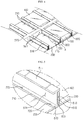
FIG. 1 is a schematic perspective view showing a battery pack according to an embodiment of the present disclosure. -
FIG. 2 is an exploded perspective view ofFIG. 1 . -
FIG. 3 is a perspective view showing a tray at which a plurality of battery modules ofFIG. 2 are loaded. -
FIG. 4 is a diagram partially showing a drainage path and drainage holes of the battery pack according to an embodiment of the present disclosure. -
FIG. 5 is an enlarged view showing a portion A ofFIG. 4 . -
FIG. 6 is a cross-sectional view, taken along the line I-I' ofFIG. 3 . -
FIG. 7 is an enlarged view showing a portion B ofFIG. 6 . -
FIG. 8 is a diagram showing a modified example of the beam frame ofFIG. 7 . -
FIGS. 9 and10 are diagrams showing states of the battery pack according to another embodiment of the present disclosure before and after the heat conduction medium makes contact with the battery modules. - The present disclosure will become more apparent by describing in detail the embodiments of the present disclosure with reference to the accompanying drawings. It should be understood that the embodiments disclosed herein are illustrative only for better understanding of the present disclosure, and that the present disclosure may be modified in various ways. In addition, for ease understanding of the present disclosure, the accompanying drawings are not drawn to real scale, but the dimensions of some components may be exaggerated.
- That is, the embodiments described in the specification and depicted shown in the drawings are only the most preferred embodiments of the present disclosure and do not represent all the technical ideas of the present disclosure, and thus it should be understood that there may be various equivalents and variations capable of replacing the embodiments at the time of this application.
-
FIG. 1 is a schematic perspective view showing a battery pack according to an embodiment of the present disclosure,FIG. 2 is an exploded perspective view ofFIG. 1 ,FIG. 3 is a perspective view showing a tray at which a plurality of battery modules ofFIG. 2 are loaded, andFIG. 4 is a diagram partially showing adrainage path 710 anddrainage holes 720 of the battery pack according to an embodiment of the present disclosure. - First, referring to
FIGS. 1 and2 , thebattery pack 10 according to an embodiment of the present disclosure includes a plurality ofbattery modules 100, and a pack case accommodating thebattery modules 100. The pack case may include atray 200 giving a space where the plurality ofbattery modules 100 are placed, apack cover 300 for packaging and accommodating the plurality ofbattery modules 100 together with thetray 200, and two side frames 400. - A plurality of battery cells are stacked in the
battery module 100, and thebattery module 100 may further include various other components. For example, the battery cell may be a pouch-type secondary battery, and a plurality of battery cells may be provided and electrically connected to each other. - Though not shown in the figures, each battery cell may include various components such as an electrode assembly, a battery case accommodating the electrode assembly, and an electrode lead protruding out of the battery case and electrically connected to the electrode assembly. The electrode lead may include a positive electrode lead and a negative electrode lead. Here, the positive electrode lead may be connected to a positive electrode plate of the electrode assembly, and the negative electrode lead may be connected to a negative electrode plate of the electrode assembly.
- The
battery module 100 may further include stacking frames and a module end plate for stacking and protecting the pouch-type secondary battery. - The stacking frames are used for stacking secondary batteries and hold the secondary batteries not to be moved. The stacking frames are provided to be stacked one another to serve as a guide for assembling the secondary batteries. For reference, the stacking frames may be replaced by various other terms such as cell covers or cartridges.
- The module end plate is an element for protecting and fixing the battery cell stack and may mean an angled structure surrounding the outer periphery of the battery cell stack or a plate-like structure padded on at least one surface of the battery cell stack. The module end plate is preferably made of a metal material with high mechanical rigidity and excellent thermal conductivity.
- Though not shown for the sake of convenience, the
battery module 100 may further include cooling pins interposed between the battery cells. The cooling fins are thin members with thermally conductive, such as aluminum, and have ends extending outward to connect to other heat absorbing media, such as aheatsink 600, to transfer the heat of the battery cells to the outside. - As described above, the
battery module 100 may refer to a collection of a plurality of battery cells or a collection of a plurality of battery cells and other components for stacking and protecting the plurality of battery cells. In addition, thebattery pack 10 of the present disclosure may refer to a collection including a plurality ofunit battery modules 100. - Referring to
FIGS. 2 and 3 , thebattery pack 10 according to this embodiment is formed using tenunit battery modules 100 in total. Theunit battery modules 100 may be loaded on the upper surface of thetray 200 in a 2 × 5 matrix form and be packaged by thepack cover 300 and two side frames 400. - The
tray 200 and thepack cover 300 may be formed in a plate shape having an approximately large area and may be disposed at the lower and upper portions of thebattery modules 100, respectively, to cover the lower and upper portions of thebattery modules 100. In addition the twoside frames 400 may be located at both side surfaces of thetray 200 to cover both side surfaces of thebattery modules 100. - In particular, two
side frames 400 of this embodiment may be provided in the form of a manifold tube. In more detail, seeingFIG. 2 , the twoside frames 400 have a passageway formed therein to serve as a pipe and have aninlet 410 or anoutlet 420 formed at the outer portion thereof and a plurality ofconnectors 430 respectively connectable to inputports 610 and output ports (located at a side opposite to the input ports) of theheatsinks 600, explained later. The twoside frames 400 serve to distribute the coolant to theheatsinks 600 or to collect the coolant from theheatsinks 600. That is, the twoside frames 400 may be regarded as components of the pack case and form supply and discharge paths of the coolant into or out of thebattery pack 10. - The pack case, namely the
tray 200, thepack cover 300 and the twoside frames 400, may give mechanical support for thebattery modules 100 and protect thebattery modules 100 from external impacts. Thus, thetray 200, thepack cover 300, and the twoside frames 400 of the pack case may be made of metal material such as steel to ensure rigidity. - Referring to
FIGS. 3 to 6 mainly, thebattery pack 10 according to the present disclosure includes a plurality of beam frames installed to traverse the upper surface of the tray to partition spaces in which a plurality of battery modules may be individually placed, and a plurality of heatsinks having a hollow structure through which the coolant may flow and selectively coupled to a part of the plurality of beam frames to face the side surface of each battery module. - In this embodiment, some of the plurality of beam frames are I-type beam frames 510, and some of the plurality of beam frames are beam frames with an angled tube form. Hereinafter, the beam frame in the form of an angled tube will be referred to as a center frame.
- More specifically, in this embodiment, as shown in
FIG. 3 , six I-type beam frames 510 may be arranged at regular intervals along the vertical direction (the X-axis direction) of thetray 200, and onecenter frame 520 may be arranged to cross the six I-type beam frames 510 and traverse the center of thetray 200. At this time, the interval between two I-type beam frames 510 corresponds to the width of theunit battery module 100, and the height of the I-type beam frame 510 may be equal to or higher than the height of thebattery module 100. Thus, partitioned individual accommodation spaces in which tenunit battery modules 100 may be loaded in a 2 × 5 matrix form may be formed on thetray 200. - Each
unit battery module 100 may be placed in the individual accommodation space so that the module electrode terminals 110 thereof face thecenter frame 520. At this time, both side surfaces of theunit battery module 100 may be supported two I-type beam frames 510 so that theunit battery module 100 is not moved. - Though not shown in detail for convenience, a plurality of
holes 521 may be formed in the outer surface of thecenter frame 520 along the length direction (the X-axis direction). In addition, a connecting module (not shown) may be provided inside thecenter frame 520. - Two
unit battery modules 100 are provided in each row, and the module electrode terminals 110 thereof may be inserted into theholes 521 of thecenter frame 520 to face each other and are connected to the connecting module. - The connecting module may be composed of bus bars made of electrically conductive material and forming a serial and/or parallel network. The connecting module may connect the plurality of
battery modules 100 in series and/or in parallel. In addition, the connecting module may be connected to aterminal 11 of thebattery pack 10 located at an outer side of the front surface of thetray 200, and the terminal 11 may be electrically connected to another device outside thebattery pack 10. - According to the 2 × N matrix arrangement of the
battery modules 100 and the configuration of the I-type beam frames 510 and thecenter frame 520, it is possible to easily fix and load thebattery modules 100, and it is possible to enhance the mechanical stiffness of thetray 200. In addition, it is possible to simplify the wiring structure without exposing a high-voltage cable or the like on thetray 200. Accordingly, the safety and space utilization of thebattery pack 10 may be improved. - Referring to
FIG. 5 , the I-type beam frame 510 according to the present disclosure includes atop portion 511 and abottom portion 513, which are horizontal with respect to the upper surface of thetray 200, and acolumn 512, which vertically connects the centers of thetop portion 511 and thebottom portion 513 to form the height of the I-type beam frame 510. - The spaces of the I-
type beam frame 510 between thetop portion 511 and thebottom portion 513 is divided into two parts by thecolumn 512. Hereinafter, both the divided spaces, namely the spaces formed at both sides of thecolumn 512, will be defined as recessedportions 514. Theheatsink 600 is mounted in the recessedportion 514 of the I-type beam frame 510. Here, theheatsink 600 may refer to an object that absorbs and emits heat from other objects by thermal contact. - More specifically, the
heatsink 600 according to the present disclosure is manufactured to have a shape corresponding to the recessedportion 514 of the I-type beam frame 510, and theinput port 610 and the output port through which the coolant flows in and out are positioned at one end and the other end thereof. Also, theheatsink 600 has a hollow structure including a flow path therein. Eachheatsink 600 may extend through thecenter frame 520 from one side of thetray 200 to the other side thereof along each I-type beam frame 510. - The coolant flowing in the flow path of the
heatsink 600 is not particularly limited as long as it easily flows in the flow path and has excellent cooling ability, but for example, it may be water that is capable of maximizing cooling efficiency due to high latent heat. - The
heatsink 600 may be integrated with the I-type beam frame 510. For example, theheatsink 600 and the I-type beam frame 510 are simply integrated by applying a thermally conductive adhesive to the inner surface of the I-type beam frame 510 and then inserting and adhering theheatsink 600 to the recessedportion 514 of the I-type beam frame 510. In this case, the space utilization of thetray 200 may be increased compared to the case where theheatsink 600 is provided at a separate position. - That is, as shown in
FIG. 7 , in thebattery pack 10 of the present disclosure, one I-type beam frame 510 and twoheatsink 600 may be combined with the corresponding shapes so that the space between the I-type beam frames 510 may be entirely utilized as a space for individually mounting theunit battery module 100, and the heat generated from eachbattery module 100 may be dissipated to both side surfaces of thebattery module 100. In addition, since the I-type beam frame 510 may also be cooled by theheatsink 600, it is possible to prevent the I-type beam frame 510 from being deformed due to the temperature rise, thereby more effectively controlling the heat of the entire battery pack structure. - In addition, the
battery pack 10 according to the present disclosure may further include adrainage path 710 formed at the lower portion of theheatsink 600 anddrainage holes 720 provided at regular intervals along thedrainage path 710. Thedrainage path 710 and the drainage holes 720 are components for discharging a coolant, which is leaked due to breakage of theheatsink 600, out of thebattery pack 10. - Referring to
FIGS. 4 and 5 again, thedrainage path 710 of this embodiment may be formed at thebottom portion 513 of the I-type beam frame. For example, thebottom portion 513 of the I-type beam frame may be concavely rounded to form thedrainage path 710. Thedrainage path 710 may be inclined at least in one direction. For example, though not shown in the figures, thedrainage path 710 may be inclined toward both ends of thetray 200 from the center of thetray 200, or may be inclined from one end of thetray 200 toward the other end thereof. - The
drainage hole 720 may be provided in plural at predetermined intervals along thedrainage path 710. For example, thebottom portion 513 of the I-type beam frame and specific locations of thetray 200 may be tapped to form the drainage holes 720 in a vertically-perforated shape. - The
drainage path 710 and the drainage holes 720 may be provided with the same pattern at the I-type beam frames 510, where theheatsinks 600 are located, and thetrays 200 at the corresponding positions. - If the
drainage path 710 and the drainage holes 720 are provided, when a coolant leaks from theheatsink 600, the coolant may flow down the wall of theheatsink 600 and be collected in the concave space of thedrainage path 710. The collected leaked coolant may flow down along theinclined drainage path 710 and be discharged below thetray 200 through the drainage holes 720 close thereto. In general, in the case of a battery pack for an electric vehicle, considering the fact that the battery pack is mounted to a lower chassis of the vehicle, the coolant discharged below thetray 200 of the battery pack may mostly drop to the ground directly. - By providing the drain structure in the battery pack, even though a coolant leaks from the
heatsink 600, the coolant may flow out of thebattery pack 10, thereby eliminating the risk of short circuit. - Subsequently, with reference to
FIG. 8 , a modified example of the beam frame according to this embodiment and a drain structure thereof will be described. The modified example of the present disclosure to be described below may be regarded as corresponding to the embodiment ofFIG. 7 . The same reference numerals denote the same components and will not be described in detail. - In this modified example, a hollow angled beam frame 510' is provided as an alternative to the I-
type beam frame 510 of the former embodiment. In addition, theheatsink 600 is positioned within the angled beam frame 510'. In this case, since theheatsink 600 is positioned inside the angled beam frame 510', the space utilization in thetray 200 may be improved. Thedrainage path 710 and thedrainage hole 720 are similar to the former embodiment. In other words, theconcave drainage path 710 may be formed at the lower end of the angled beam frame 510', and the plurality ofdrainage holes 720 may be formed along the length direction of thedrainage path 710. - Meanwhile, even though the angled beam frame 510' and the
heatsink 600 are structurally distinguished in the above description, a flow path may be formed inside the hollow angled beam frame as an example. Thus, the angled beam frame may be as the heatsink by itself. In this case, the angled beam frame may be regarded as a structure, and the heatsink may be regarded as a coolant flowing in the flow path inside the angled beam frame. In addition, thedrainage path 710 and thedrainage hole 720 may be located at thecorresponding tray 200 where the angled beam frame 510' is located. -
FIGS. 9 and10 are diagrams showing states of the battery pack according to another embodiment of the present disclosure before and after the heat conduction medium makes contact with the battery modules. - The battery pack according to another embodiment of the present disclosure may further include a
heat conduction medium 800 interposed at a thermal interface of theheatsink 600 and thebattery module 100. - The
heat conduction medium 800 may not be particularly limited in its thickness and structure as long as it is a thin member having thermal conductivity and is capable of filling the gap between thebattery module 100 and theheatsink 600. For example, a sheet-shaped plate made of a metal material may be used. The metal material may be aluminum or aluminum alloy having high thermal conductivity and light weight among metals, but is not limited thereto. For example, copper, gold and silver may be used. In addition to the metal, ceramic materials such as aluminum nitride and silicon carbide are also possible. - In particular, the
heat conduction medium 800 according to another embodiment of the present disclosure may include aplate surface 810 attached to one surface of theheatsink 600 and aprotrusion 820 protruding perpendicularly with respect to theplate surface 810. Theprotrusion 820 may be made of, for example, silicone rubber that is elastically deformed when an external pressure is applied thereto. The silicone rubber has excellent thermal conductivity and heat dissipation properties and also allows elastic deformation. - As an alternative of the silicon rubber, a carbon flake or filler rubbers filled with a solution in which a highly conductive metal flake is mixed may also be applied.
- In the
heat conduction medium 800, when theunit battery module 100 is placed in a lower direction in the accommodation space between the I-type beam frames 510, theprotrusion 820 is pressed by the side surface of thebattery module 100 and thus bent downwards as shown inFIG. 10 . At this time, since theprotrusion 820 has an elastic restoring force to return to its original shape, theheat conduction medium 800 may strongly contact the side surface of thebattery module 100. Accordingly, if theunit battery module 100 is inserted into the accommodation space, the left and right side surfaces of thebattery module 100 are respectively kept in close contact with theheat conduction medium 800 as described above, so that the heat is easily transferred from thebattery module 100 to theheatsink 600. - In addition, the
heat conduction medium 800 may serve to hold thebattery module 100. In other words, since theprotrusions 820 of twoheat conduction medium 800 serve to hold thebattery module 100 at both side surfaces of thebattery module 100, even though an external shock is applied to thebattery pack 10, it is prevented that thebattery module 100 is moved, and thus it is also possible to prevent a gap from being created between thebattery module 100 and theheatsink 600. - As described above, according to the present disclosure, the stiffness and volume ratio of the
battery pack 10 may be increased, and the cooling configuration for theindividual battery module 100 may be compactly implemented. In addition, the contacting force of theindividual battery module 100 to theheatsink 600 may be enhanced by using theheat conduction medium 800 having a protrusion shape and capable of elastic deformation. Accordingly, the cooling efficiency may be improved, and theindividual battery modules 100 may be stably supported even though an external shock or vibration is applied thereto. - Meanwhile, the battery pack according to an embodiment of the present disclosure may further include various devices (not shown) such as a battery management system (BMS), a current sensor, a fuse and the like, for controlling charge and discharge of the battery modules.
- The vehicle according to the present disclosure may include the battery pack according to the present disclosure. The battery pack may be applied not only to vehicles such as electric vehicles and hybrid electric vehicles but also to IT products.
- The present disclosure has been described in detail. However, it should be understood that the detailed description and specific examples, while indicating preferred embodiments of the disclosure, are given by way of illustration only, since various changes and modifications within the scope of the disclosure will become apparent to those skilled in the art from this detailed description.
Claims (15)
- A battery pack, comprising:a plurality of battery modules;a tray giving a space where the plurality of battery modules are placed;a plurality of beam frames installed to traverse an upper surface of the tray to partition spaces where the plurality of battery modules are capable of being individually placed; anda plurality of heatsinks formed to have a hollow structure through which a coolant flows, the plurality of heatsinks being selectively coupled to a part of the plurality of beam frames so as to be disposed to face a side surface of the battery modules, respectively,wherein a drainage hole is respectively provided at the tray and the beam frame and perforated in a lower direction with respect to the heatsink.
- The battery pack according to claim 1,
wherein a drainage path having a concave shape is formed at a lower portion of the heatsink. - The battery pack according to claim 2,
wherein the drainage hole is provided in plural, and the plurality of drainage holes are provided along the drainage path at predetermined intervals. - The battery pack according to claim 3,
wherein the drainage path is inclined in at least one direction. - The battery pack according to claim 1,
wherein a part of the plurality of beam frames are I-type beam frames, and
wherein the heatsink is provided to be mountable to recessed portions formed at both sides of a column that forms a height of the I-type beam frame. - The battery pack according to claim 5,
wherein the heatsink is shaped corresponding to the recessed portion and is adhered thereto by a thermal conductive adhesive to be integrated with the I-type beam frame. - The battery pack according to claim 5,
wherein another part of the plurality of beam frames is a single center frame that traverses a center of the tray, and the I-type beam frames intersect the center frame and are disposed at the tray at regular intervals, so that the plurality of battery modules are arranged in a 2 × N matrix. - The battery pack according to claim 7,
wherein each of the heatsinks has an input port and an output port provided at one end and the other end thereof so that a coolant flows in or out therethrough, and is installed to traverse the upper surface of the tray along the I-type beam frame through the center frame. - The battery pack according to claim 8, further comprising:a pack cover configured to cover an upper portion of the tray and two side frames configured to cover both side surfaces of the tray, respectively,wherein the two side frames are provided in the form of a manifold tube communicating with the input ports and the output ports of the heatsinks to form a path for supplying and discharging the coolant.
- The battery pack according to claim 7,
wherein the center frame is provided in the form of an angled tube having a plurality of holes formed at an outer side surface thereof, and
wherein a connecting module is provided in the center frame to connect the plurality of battery modules in series and/or in parallel. - The battery pack according to claim 1,
wherein a part of the plurality of beam frames is an angled beam frame with a hollow therein, and
wherein the heatsink is located inside the angled beam frame. - The battery pack according to claim 1, further comprising:
a heat conduction medium interposed at a thermal interface of the heatsink and the battery module. - The battery pack according to claim 12,
wherein the heat conduction medium has a plate surface attached to one surface of the heatsink and a protrusion vertically protruding from the plate surface, and the protrusion has a property of elastically deforming when an external pressure is applied thereto. - The battery pack according to claim 13,
wherein the heat conduction medium is made of a silicon rubber. - An electric vehicle, comprising the battery pack defined in any one of claims 1 to 14.
Priority Applications (1)
| Application Number | Priority Date | Filing Date | Title |
|---|---|---|---|
| PL18780297T PL3573129T3 (en) | 2017-04-04 | 2018-03-26 | Battery pack having crash beam and drainage structure |
Applications Claiming Priority (2)
| Application Number | Priority Date | Filing Date | Title |
|---|---|---|---|
| KR1020170043912A KR102065099B1 (en) | 2017-04-04 | 2017-04-04 | Battery Pack having crash beam and drain structure |
| PCT/KR2018/003527 WO2018186616A1 (en) | 2017-04-04 | 2018-03-26 | Battery pack having crash beam and drainage structure |
Publications (3)
| Publication Number | Publication Date |
|---|---|
| EP3573129A1 true EP3573129A1 (en) | 2019-11-27 |
| EP3573129A4 EP3573129A4 (en) | 2020-03-04 |
| EP3573129B1 EP3573129B1 (en) | 2021-09-01 |
Family
ID=63712618
Family Applications (1)
| Application Number | Title | Priority Date | Filing Date |
|---|---|---|---|
| EP18780297.0A Active EP3573129B1 (en) | 2017-04-04 | 2018-03-26 | Battery pack having crash beam and drainage structure |
Country Status (7)
| Country | Link |
|---|---|
| US (1) | US11450913B2 (en) |
| EP (1) | EP3573129B1 (en) |
| JP (1) | JP6750117B2 (en) |
| KR (1) | KR102065099B1 (en) |
| CN (2) | CN108695458B (en) |
| PL (1) | PL3573129T3 (en) |
| WO (1) | WO2018186616A1 (en) |
Cited By (10)
| Publication number | Priority date | Publication date | Assignee | Title |
|---|---|---|---|---|
| EP3570364A4 (en) * | 2017-04-06 | 2020-02-26 | LG Chem, Ltd. | Battery pack equipped with heat conduction medium having a louver fin shape |
| CN111029512A (en) * | 2020-01-19 | 2020-04-17 | 王佳先 | Embedded liquid cooling integrated battery box |
| EP3759761A4 (en) * | 2018-03-01 | 2021-09-08 | Shape Corp. | Cooling system integrated with vehicle battery tray |
| EP3934008A1 (en) * | 2020-07-03 | 2022-01-05 | Witzenmann GmbH | Temperature control device for a battery cell assembly, battery cell assembly and method for controlling the temperature of such |
| EP3958379A4 (en) * | 2020-04-29 | 2022-09-28 | LG Energy Solution, Ltd. | Battery module and battery pack comprising same |
| WO2022214570A1 (en) * | 2021-04-07 | 2022-10-13 | Valeo Systemes Thermiques | Cooling system for an electronic system |
| EP4020672A4 (en) * | 2020-04-28 | 2022-12-28 | Lg Energy Solution, Ltd. | Battery pack and device including same |
| GB2609386A (en) * | 2020-05-29 | 2023-02-08 | Porsche Ag | Traction battery module for a vehicle |
| EP4404347A1 (en) * | 2023-01-17 | 2024-07-24 | Xiamen Ampack Technology Limited | Battery pack and electrical device |
| EP4109633A4 (en) * | 2020-11-23 | 2024-08-14 | Lg Energy Solution Ltd | Battery pack including structure for suppressing thermal diffusion |
Families Citing this family (49)
| Publication number | Priority date | Publication date | Assignee | Title |
|---|---|---|---|---|
| KR102065099B1 (en) * | 2017-04-04 | 2020-01-10 | 주식회사 엘지화학 | Battery Pack having crash beam and drain structure |
| FR3088143B1 (en) * | 2018-11-06 | 2022-07-08 | Valeo Systemes Thermiques | COOLING ASSEMBLY, IN PARTICULAR FOR VEHICLE BATTERIES |
| WO2020102361A1 (en) * | 2018-11-13 | 2020-05-22 | Collins Tyler | Battery module frame configuration |
| DE102018132171A1 (en) * | 2018-12-13 | 2020-06-18 | Thyssenkrupp Steel Europe Ag | Battery case and usage |
| JP7199303B2 (en) * | 2019-05-17 | 2023-01-05 | 株式会社東芝 | Battery modules, battery packs and vehicles |
| KR20210015551A (en) * | 2019-08-02 | 2021-02-10 | 주식회사 엘지화학 | Battery pack and vehicle comprising the battery pack |
| KR20210017273A (en) * | 2019-08-07 | 2021-02-17 | 주식회사 엘지화학 | Battery pack that incorporates a battery module and a rigid beam and employs a reverse assembly |
| CN111106280B (en) | 2019-08-27 | 2021-05-25 | 宁德时代新能源科技股份有限公司 | Battery pack |
| CN110474005A (en) * | 2019-09-06 | 2019-11-19 | 荣盛盟固利新能源科技有限公司 | Lithium battery temperature management case and lithium battery system |
| KR20210053054A (en) | 2019-11-01 | 2021-05-11 | 에스케이이노베이션 주식회사 | Battery module |
| CN112310541B (en) * | 2019-11-19 | 2022-03-29 | 宁德时代新能源科技股份有限公司 | Battery pack and vehicle |
| KR20210109316A (en) * | 2020-02-27 | 2021-09-06 | 주식회사 엘지에너지솔루션 | Energy storage system having superabsorbent sheets |
| CN113540662B (en) * | 2020-03-31 | 2022-10-18 | 比亚迪股份有限公司 | Battery pack, battery tray thereof and vehicle |
| JP7442920B2 (en) * | 2020-04-09 | 2024-03-05 | エルジー エナジー ソリューション リミテッド | Battery module and battery pack containing it |
| KR20210127027A (en) * | 2020-04-13 | 2021-10-21 | 주식회사 엘지에너지솔루션 | Battery module and manufacturing method thereof |
| KR20210127320A (en) * | 2020-04-14 | 2021-10-22 | 주식회사 엘지에너지솔루션 | Battery pack and device including the same |
| KR20210127319A (en) * | 2020-04-14 | 2021-10-22 | 주식회사 엘지에너지솔루션 | Battery pack and device including the same |
| CN111509156A (en) * | 2020-04-15 | 2020-08-07 | 力神动力电池系统有限公司 | Highly-integrated compact battery system |
| KR20210133531A (en) * | 2020-04-29 | 2021-11-08 | 주식회사 엘지에너지솔루션 | Battery pack and device including the same |
| KR20210134164A (en) * | 2020-04-29 | 2021-11-09 | 주식회사 엘지에너지솔루션 | Battery Pack and Electronic Device Comprising the Same and Vehicle |
| KR20210133788A (en) * | 2020-04-29 | 2021-11-08 | 주식회사 엘지에너지솔루션 | A battery pack having space efficiency and structure stability of a cooling path and a vehicle including the same |
| KR20210147657A (en) * | 2020-05-29 | 2021-12-07 | 주식회사 엘지에너지솔루션 | Heat sink |
| CN111619338B (en) * | 2020-05-31 | 2022-06-07 | 重庆长安汽车股份有限公司 | Water storage bottle and double-cooling system |
| EP4068480A4 (en) * | 2020-09-04 | 2024-08-14 | Lg Energy Solution Ltd | Battery pack, vehicle, and electronic device comprising same |
| KR102642182B1 (en) * | 2020-10-19 | 2024-03-05 | 지앙수 컨템포러리 엠퍼렉스 테크놀로지 리미티드 | Battery box body, battery, electrical device, battery manufacturing method and device |
| KR20220063050A (en) * | 2020-11-09 | 2022-05-17 | 주식회사 엘지에너지솔루션 | Battery pack and Vehicle comprising the same |
| KR102269290B1 (en) * | 2020-11-10 | 2021-06-25 | 주식회사 원진 | Battery cooling apparatus of electric vehicle |
| KR20220065601A (en) * | 2020-11-13 | 2022-05-20 | 주식회사 엘지에너지솔루션 | Battery pack having a structure capable of swelling control and Vehicle including the same |
| FR3122774A1 (en) * | 2021-05-10 | 2022-11-11 | Psa Automobiles Sa | MODULAR BATTERY SYSTEM EXCHANGES CALORIES WITH ITS STRUCTURE |
| CN115347295A (en) * | 2021-05-14 | 2022-11-15 | 中创新航科技股份有限公司 | Battery box, battery package and vehicle |
| CN113232526B (en) * | 2021-05-24 | 2023-04-07 | 上海兰钧新能源科技有限公司 | Battery pack and automobile |
| KR20220169703A (en) * | 2021-06-21 | 2022-12-28 | 주식회사 엘지에너지솔루션 | Battery pack and device including the same |
| FR3125360A1 (en) * | 2021-07-16 | 2023-01-20 | Faurecia Systemes D'echappement | Electricity storage battery and corresponding manufacturing method |
| KR20230015646A (en) * | 2021-07-23 | 2023-01-31 | 에스케이온 주식회사 | Battery pack case, and Battery pack having the same |
| CA3210723A1 (en) * | 2021-09-09 | 2023-03-16 | Jin-Yong Park | Cell assembly to which longitudinal extension structure of pouch batter y cell is applied and battery pack including the same?. |
| KR20230040668A (en) * | 2021-09-16 | 2023-03-23 | 주식회사 엘지에너지솔루션 | Battery pack and device including the same |
| CN114013334B (en) * | 2021-11-09 | 2023-09-15 | 成都工贸职业技术学院 | New energy automobile battery state detection processing apparatus |
| KR102686923B1 (en) * | 2021-12-23 | 2024-07-19 | 비나텍주식회사 | Air-cooled cooling structure of electric energy storage module |
| KR102664969B1 (en) | 2022-01-26 | 2024-05-10 | 주식회사 엘지에너지솔루션 | Battery pack and a vehicle having the same |
| EP4395004A1 (en) * | 2022-01-27 | 2024-07-03 | Contemporary Amperex Technology Co., Limited | Battery, electrical device, battery preparation method, and battery preparation device |
| WO2023166809A1 (en) * | 2022-03-01 | 2023-09-07 | パナソニックエナジ-株式会社 | Battery module |
| KR102676203B1 (en) * | 2022-09-07 | 2024-06-19 | 주식회사 엘지에너지솔루션 | Battery pack having thermal propagation delay structure |
| CN115366703B (en) * | 2022-10-21 | 2023-01-24 | 宜宾长盈精密技术有限公司 | Aluminum alloy battery tray |
| CN115692925B (en) * | 2022-11-04 | 2023-11-03 | 江苏奥特帕斯新能源科技有限公司 | Heat dissipation type battery box structure of electric automobile, assembly tool and assembly method of assembly tool |
| WO2024112060A1 (en) * | 2022-11-22 | 2024-05-30 | 주식회사 엘지에너지솔루션 | Battery pack and device comprising same |
| FR3142607A1 (en) * | 2022-11-30 | 2024-05-31 | Faurecia Systemes D'echappement | Refrigerated electricity storage battery |
| WO2024117793A1 (en) * | 2022-12-02 | 2024-06-06 | 주식회사 엘지에너지솔루션 | Battery pack and manufacturing method therefor |
| KR20240092302A (en) * | 2022-12-14 | 2024-06-24 | 에스케이온 주식회사 | Battery Pack |
| KR20240130464A (en) * | 2023-02-22 | 2024-08-29 | 에스케이온 주식회사 | Battery case and Battery pack including the same |
Family Cites Families (21)
| Publication number | Priority date | Publication date | Assignee | Title |
|---|---|---|---|---|
| JPH0752659A (en) | 1993-08-19 | 1995-02-28 | Nissan Motor Co Ltd | Structure for holding battery of electric vehicle in place |
| JP4494719B2 (en) * | 2003-01-24 | 2010-06-30 | 古河電気工業株式会社 | Storage battery heat sink and storage battery cooling device |
| KR100612305B1 (en) | 2004-06-25 | 2006-08-11 | 삼성에스디아이 주식회사 | Secondary battery module |
| JP4508221B2 (en) * | 2007-08-27 | 2010-07-21 | 豊田合成株式会社 | Battery assembly |
| JP5136078B2 (en) | 2008-01-22 | 2013-02-06 | 豊田合成株式会社 | Battery assembly |
| JP2009238643A (en) * | 2008-03-27 | 2009-10-15 | Sanyo Electric Co Ltd | Battery block for vehicle |
| JP2010092598A (en) | 2008-10-03 | 2010-04-22 | Gs Yuasa Corporation | Battery pack |
| US8557415B2 (en) * | 2009-04-22 | 2013-10-15 | Tesla Motors, Inc. | Battery pack venting system |
| JP5639835B2 (en) | 2010-09-30 | 2014-12-10 | 株式会社リチウムエナジージャパン | Battery pack and electric vehicle equipped with the same |
| JP5592501B2 (en) * | 2010-11-16 | 2014-09-17 | 本田技研工業株式会社 | Battery cooling structure |
| KR101317523B1 (en) | 2010-12-20 | 2013-10-15 | 인지컨트롤스 주식회사 | Battery protection apparatus for a battery car |
| JP5601283B2 (en) * | 2011-06-17 | 2014-10-08 | トヨタ自動車株式会社 | Power storage device, spacer |
| JP2014026825A (en) * | 2012-07-26 | 2014-02-06 | Mitsubishi Motors Corp | Battery cooler |
| JP6110268B2 (en) * | 2013-09-30 | 2017-04-05 | 三菱自動車工業株式会社 | Battery temperature control device |
| DE102013219665B4 (en) * | 2013-09-30 | 2021-05-06 | Vitesco Technologies GmbH | Cooling arrangement |
| KR101649154B1 (en) * | 2014-02-24 | 2016-08-18 | 엘지전자 주식회사 | Battery Pack |
| KR102273784B1 (en) | 2014-10-30 | 2021-07-06 | 삼성에스디아이 주식회사 | Battery pack |
| KR20170043912A (en) | 2015-10-14 | 2017-04-24 | 권혁수 | Dental impression tray for various purpose |
| KR101690234B1 (en) | 2015-11-04 | 2016-12-27 | (주)캠시스 | Temperature controlling system of battery pack |
| CN105552268B (en) * | 2016-01-30 | 2018-06-22 | 华南理工大学 | It is a kind of to fill gelled multiple exit batteries of electric automobile air cooling battery case |
| KR102065099B1 (en) * | 2017-04-04 | 2020-01-10 | 주식회사 엘지화학 | Battery Pack having crash beam and drain structure |
-
2017
- 2017-04-04 KR KR1020170043912A patent/KR102065099B1/en active IP Right Grant
-
2018
- 2018-03-26 WO PCT/KR2018/003527 patent/WO2018186616A1/en unknown
- 2018-03-26 PL PL18780297T patent/PL3573129T3/en unknown
- 2018-03-26 EP EP18780297.0A patent/EP3573129B1/en active Active
- 2018-03-26 JP JP2019524457A patent/JP6750117B2/en active Active
- 2018-03-26 US US16/349,530 patent/US11450913B2/en active Active
- 2018-04-03 CN CN201810288520.5A patent/CN108695458B/en active Active
- 2018-04-03 CN CN201820467913.8U patent/CN208078058U/en active Active
Cited By (15)
| Publication number | Priority date | Publication date | Assignee | Title |
|---|---|---|---|---|
| US11133542B2 (en) | 2017-04-06 | 2021-09-28 | Lg Chem, Ltd. | Battery pack including heat conduction medium with louver fin shape |
| EP3570364A4 (en) * | 2017-04-06 | 2020-02-26 | LG Chem, Ltd. | Battery pack equipped with heat conduction medium having a louver fin shape |
| EP3759761A4 (en) * | 2018-03-01 | 2021-09-08 | Shape Corp. | Cooling system integrated with vehicle battery tray |
| CN111029512B (en) * | 2020-01-19 | 2022-03-15 | 王佳先 | Embedded liquid cooling integrated battery box |
| CN111029512A (en) * | 2020-01-19 | 2020-04-17 | 王佳先 | Embedded liquid cooling integrated battery box |
| EP4020672A4 (en) * | 2020-04-28 | 2022-12-28 | Lg Energy Solution, Ltd. | Battery pack and device including same |
| EP3958379A4 (en) * | 2020-04-29 | 2022-09-28 | LG Energy Solution, Ltd. | Battery module and battery pack comprising same |
| GB2609386A (en) * | 2020-05-29 | 2023-02-08 | Porsche Ag | Traction battery module for a vehicle |
| US11777159B2 (en) | 2020-05-29 | 2023-10-03 | Dr. Ing. H.C. F. Porsche Aktiengesellschaft | Traction battery module for a vehicle |
| GB2609386B (en) * | 2020-05-29 | 2023-11-15 | Porsche Ag | Traction battery module for a vehicle |
| EP3934008A1 (en) * | 2020-07-03 | 2022-01-05 | Witzenmann GmbH | Temperature control device for a battery cell assembly, battery cell assembly and method for controlling the temperature of such |
| EP4109633A4 (en) * | 2020-11-23 | 2024-08-14 | Lg Energy Solution Ltd | Battery pack including structure for suppressing thermal diffusion |
| WO2022214570A1 (en) * | 2021-04-07 | 2022-10-13 | Valeo Systemes Thermiques | Cooling system for an electronic system |
| FR3121644A1 (en) * | 2021-04-07 | 2022-10-14 | Valeo Systemes Thermiques | Cooling system for electronic system. |
| EP4404347A1 (en) * | 2023-01-17 | 2024-07-24 | Xiamen Ampack Technology Limited | Battery pack and electrical device |
Also Published As
| Publication number | Publication date |
|---|---|
| CN108695458A (en) | 2018-10-23 |
| CN108695458B (en) | 2020-04-24 |
| EP3573129B1 (en) | 2021-09-01 |
| CN208078058U (en) | 2018-11-09 |
| PL3573129T3 (en) | 2022-01-31 |
| JP2019536214A (en) | 2019-12-12 |
| US20200185672A1 (en) | 2020-06-11 |
| JP6750117B2 (en) | 2020-09-02 |
| WO2018186616A1 (en) | 2018-10-11 |
| KR102065099B1 (en) | 2020-01-10 |
| US11450913B2 (en) | 2022-09-20 |
| EP3573129A4 (en) | 2020-03-04 |
| KR20180112618A (en) | 2018-10-12 |
Similar Documents
| Publication | Publication Date | Title |
|---|---|---|
| EP3573129B1 (en) | Battery pack having crash beam and drainage structure | |
| US10971770B2 (en) | Battery pack having crash beam structure | |
| US11133542B2 (en) | Battery pack including heat conduction medium with louver fin shape | |
| CN110710051B (en) | Battery pack | |
| KR102112716B1 (en) | Battery module, battery pack the battery module and vehicle comprising the battery pack | |
| KR102326596B1 (en) | Battery Pack Having Mounting Structure | |
| KR20190047499A (en) | Battery module having fixing structure intergrated with cooling material for battery cells and Battery pack including the same | |
| EP3739662A2 (en) | Battery module | |
| CN113939948B (en) | Battery module, battery pack and electronic device | |
| CN114041230B (en) | Top-cooled battery pack | |
| KR20200080067A (en) | Battery module, battery pack comprising the battery module and vehicle comprising the battery pack | |
| CN111226344A (en) | Battery module and battery pack including the same | |
| CN113906621B (en) | Battery module and battery pack including the same | |
| KR102699573B1 (en) | Bettery module | |
| CN116457985A (en) | Battery pack and device comprising same | |
| KR20210017172A (en) | Under Body for Vehicle |
Legal Events
| Date | Code | Title | Description |
|---|---|---|---|
| STAA | Information on the status of an ep patent application or granted ep patent |
Free format text: STATUS: THE INTERNATIONAL PUBLICATION HAS BEEN MADE |
|
| PUAI | Public reference made under article 153(3) epc to a published international application that has entered the european phase |
Free format text: ORIGINAL CODE: 0009012 |
|
| STAA | Information on the status of an ep patent application or granted ep patent |
Free format text: STATUS: REQUEST FOR EXAMINATION WAS MADE |
|
| 17P | Request for examination filed |
Effective date: 20190820 |
|
| AK | Designated contracting states |
Kind code of ref document: A1 Designated state(s): AL AT BE BG CH CY CZ DE DK EE ES FI FR GB GR HR HU IE IS IT LI LT LU LV MC MK MT NL NO PL PT RO RS SE SI SK SM TR |
|
| AX | Request for extension of the european patent |
Extension state: BA ME |
|
| A4 | Supplementary search report drawn up and despatched |
Effective date: 20200205 |
|
| RIC1 | Information provided on ipc code assigned before grant |
Ipc: H01M 10/6568 20140101ALI20200130BHEP Ipc: H01M 10/653 20140101ALI20200130BHEP Ipc: H01M 10/625 20140101ALI20200130BHEP Ipc: H01M 10/6567 20140101ALI20200130BHEP Ipc: H01M 2/10 20060101AFI20200130BHEP Ipc: H01M 10/6551 20140101ALI20200130BHEP Ipc: H01M 10/613 20140101ALI20200130BHEP Ipc: H01M 2/36 20060101ALI20200130BHEP Ipc: H01M 10/6556 20140101ALI20200130BHEP |
|
| DAV | Request for validation of the european patent (deleted) | ||
| DAX | Request for extension of the european patent (deleted) | ||
| REG | Reference to a national code |
Ref country code: DE Ref legal event code: R079 Ref document number: 602018022972 Country of ref document: DE Free format text: PREVIOUS MAIN CLASS: H01M0002100000 Ipc: H01M0010655100 |
|
| RIC1 | Information provided on ipc code assigned before grant |
Ipc: H01M 10/6556 20140101ALI20210218BHEP Ipc: H01M 10/653 20140101ALI20210218BHEP Ipc: H01M 50/60 20210101ALI20210218BHEP Ipc: H01M 10/6568 20140101ALI20210218BHEP Ipc: H01M 10/625 20140101ALI20210218BHEP Ipc: H01M 10/613 20140101ALI20210218BHEP Ipc: H01M 10/6567 20140101ALI20210218BHEP Ipc: H01M 10/6551 20140101AFI20210218BHEP Ipc: H01M 50/20 20210101ALI20210218BHEP |
|
| GRAP | Despatch of communication of intention to grant a patent |
Free format text: ORIGINAL CODE: EPIDOSNIGR1 |
|
| STAA | Information on the status of an ep patent application or granted ep patent |
Free format text: STATUS: GRANT OF PATENT IS INTENDED |
|
| INTG | Intention to grant announced |
Effective date: 20210329 |
|
| GRAS | Grant fee paid |
Free format text: ORIGINAL CODE: EPIDOSNIGR3 |
|
| GRAA | (expected) grant |
Free format text: ORIGINAL CODE: 0009210 |
|
| STAA | Information on the status of an ep patent application or granted ep patent |
Free format text: STATUS: THE PATENT HAS BEEN GRANTED |
|
| AK | Designated contracting states |
Kind code of ref document: B1 Designated state(s): AL AT BE BG CH CY CZ DE DK EE ES FI FR GB GR HR HU IE IS IT LI LT LU LV MC MK MT NL NO PL PT RO RS SE SI SK SM TR |
|
| REG | Reference to a national code |
Ref country code: GB Ref legal event code: FG4D |
|
| REG | Reference to a national code |
Ref country code: AT Ref legal event code: REF Ref document number: 1427167 Country of ref document: AT Kind code of ref document: T Effective date: 20210915 Ref country code: CH Ref legal event code: EP |
|
| REG | Reference to a national code |
Ref country code: DE Ref legal event code: R096 Ref document number: 602018022972 Country of ref document: DE |
|
| REG | Reference to a national code |
Ref country code: SE Ref legal event code: TRGR |
|
| REG | Reference to a national code |
Ref country code: IE Ref legal event code: FG4D |
|
| REG | Reference to a national code |
Ref country code: LT Ref legal event code: MG9D |
|
| REG | Reference to a national code |
Ref country code: NL Ref legal event code: MP Effective date: 20210901 |
|
| RAP2 | Party data changed (patent owner data changed or rights of a patent transferred) |
Owner name: LG ENERGY SOLUTION LTD. |
|
| PG25 | Lapsed in a contracting state [announced via postgrant information from national office to epo] |
Ref country code: BG Free format text: LAPSE BECAUSE OF FAILURE TO SUBMIT A TRANSLATION OF THE DESCRIPTION OR TO PAY THE FEE WITHIN THE PRESCRIBED TIME-LIMIT Effective date: 20211201 Ref country code: LT Free format text: LAPSE BECAUSE OF FAILURE TO SUBMIT A TRANSLATION OF THE DESCRIPTION OR TO PAY THE FEE WITHIN THE PRESCRIBED TIME-LIMIT Effective date: 20210901 Ref country code: NO Free format text: LAPSE BECAUSE OF FAILURE TO SUBMIT A TRANSLATION OF THE DESCRIPTION OR TO PAY THE FEE WITHIN THE PRESCRIBED TIME-LIMIT Effective date: 20211201 Ref country code: RS Free format text: LAPSE BECAUSE OF FAILURE TO SUBMIT A TRANSLATION OF THE DESCRIPTION OR TO PAY THE FEE WITHIN THE PRESCRIBED TIME-LIMIT Effective date: 20210901 Ref country code: HR Free format text: LAPSE BECAUSE OF FAILURE TO SUBMIT A TRANSLATION OF THE DESCRIPTION OR TO PAY THE FEE WITHIN THE PRESCRIBED TIME-LIMIT Effective date: 20210901 Ref country code: FI Free format text: LAPSE BECAUSE OF FAILURE TO SUBMIT A TRANSLATION OF THE DESCRIPTION OR TO PAY THE FEE WITHIN THE PRESCRIBED TIME-LIMIT Effective date: 20210901 Ref country code: ES Free format text: LAPSE BECAUSE OF FAILURE TO SUBMIT A TRANSLATION OF THE DESCRIPTION OR TO PAY THE FEE WITHIN THE PRESCRIBED TIME-LIMIT Effective date: 20210901 |
|
| REG | Reference to a national code |
Ref country code: AT Ref legal event code: MK05 Ref document number: 1427167 Country of ref document: AT Kind code of ref document: T Effective date: 20210901 |
|
| PG25 | Lapsed in a contracting state [announced via postgrant information from national office to epo] |
Ref country code: LV Free format text: LAPSE BECAUSE OF FAILURE TO SUBMIT A TRANSLATION OF THE DESCRIPTION OR TO PAY THE FEE WITHIN THE PRESCRIBED TIME-LIMIT Effective date: 20210901 Ref country code: GR Free format text: LAPSE BECAUSE OF FAILURE TO SUBMIT A TRANSLATION OF THE DESCRIPTION OR TO PAY THE FEE WITHIN THE PRESCRIBED TIME-LIMIT Effective date: 20211202 |
|
| RAP4 | Party data changed (patent owner data changed or rights of a patent transferred) |
Owner name: LG ENERGY SOLUTION, LTD. |
|
| PG25 | Lapsed in a contracting state [announced via postgrant information from national office to epo] |
Ref country code: AT Free format text: LAPSE BECAUSE OF FAILURE TO SUBMIT A TRANSLATION OF THE DESCRIPTION OR TO PAY THE FEE WITHIN THE PRESCRIBED TIME-LIMIT Effective date: 20210901 |
|
| PG25 | Lapsed in a contracting state [announced via postgrant information from national office to epo] |
Ref country code: IS Free format text: LAPSE BECAUSE OF FAILURE TO SUBMIT A TRANSLATION OF THE DESCRIPTION OR TO PAY THE FEE WITHIN THE PRESCRIBED TIME-LIMIT Effective date: 20220101 Ref country code: SM Free format text: LAPSE BECAUSE OF FAILURE TO SUBMIT A TRANSLATION OF THE DESCRIPTION OR TO PAY THE FEE WITHIN THE PRESCRIBED TIME-LIMIT Effective date: 20210901 Ref country code: SK Free format text: LAPSE BECAUSE OF FAILURE TO SUBMIT A TRANSLATION OF THE DESCRIPTION OR TO PAY THE FEE WITHIN THE PRESCRIBED TIME-LIMIT Effective date: 20210901 Ref country code: RO Free format text: LAPSE BECAUSE OF FAILURE TO SUBMIT A TRANSLATION OF THE DESCRIPTION OR TO PAY THE FEE WITHIN THE PRESCRIBED TIME-LIMIT Effective date: 20210901 Ref country code: PT Free format text: LAPSE BECAUSE OF FAILURE TO SUBMIT A TRANSLATION OF THE DESCRIPTION OR TO PAY THE FEE WITHIN THE PRESCRIBED TIME-LIMIT Effective date: 20220103 Ref country code: NL Free format text: LAPSE BECAUSE OF FAILURE TO SUBMIT A TRANSLATION OF THE DESCRIPTION OR TO PAY THE FEE WITHIN THE PRESCRIBED TIME-LIMIT Effective date: 20210901 Ref country code: EE Free format text: LAPSE BECAUSE OF FAILURE TO SUBMIT A TRANSLATION OF THE DESCRIPTION OR TO PAY THE FEE WITHIN THE PRESCRIBED TIME-LIMIT Effective date: 20210901 Ref country code: CZ Free format text: LAPSE BECAUSE OF FAILURE TO SUBMIT A TRANSLATION OF THE DESCRIPTION OR TO PAY THE FEE WITHIN THE PRESCRIBED TIME-LIMIT Effective date: 20210901 Ref country code: AL Free format text: LAPSE BECAUSE OF FAILURE TO SUBMIT A TRANSLATION OF THE DESCRIPTION OR TO PAY THE FEE WITHIN THE PRESCRIBED TIME-LIMIT Effective date: 20210901 |
|
| REG | Reference to a national code |
Ref country code: DE Ref legal event code: R097 Ref document number: 602018022972 Country of ref document: DE |
|
| PLBE | No opposition filed within time limit |
Free format text: ORIGINAL CODE: 0009261 |
|
| STAA | Information on the status of an ep patent application or granted ep patent |
Free format text: STATUS: NO OPPOSITION FILED WITHIN TIME LIMIT |
|
| PG25 | Lapsed in a contracting state [announced via postgrant information from national office to epo] |
Ref country code: IT Free format text: LAPSE BECAUSE OF FAILURE TO SUBMIT A TRANSLATION OF THE DESCRIPTION OR TO PAY THE FEE WITHIN THE PRESCRIBED TIME-LIMIT Effective date: 20210901 Ref country code: DK Free format text: LAPSE BECAUSE OF FAILURE TO SUBMIT A TRANSLATION OF THE DESCRIPTION OR TO PAY THE FEE WITHIN THE PRESCRIBED TIME-LIMIT Effective date: 20210901 |
|
| 26N | No opposition filed |
Effective date: 20220602 |
|
| PG25 | Lapsed in a contracting state [announced via postgrant information from national office to epo] |
Ref country code: SI Free format text: LAPSE BECAUSE OF FAILURE TO SUBMIT A TRANSLATION OF THE DESCRIPTION OR TO PAY THE FEE WITHIN THE PRESCRIBED TIME-LIMIT Effective date: 20210901 |
|
| PG25 | Lapsed in a contracting state [announced via postgrant information from national office to epo] |
Ref country code: MC Free format text: LAPSE BECAUSE OF FAILURE TO SUBMIT A TRANSLATION OF THE DESCRIPTION OR TO PAY THE FEE WITHIN THE PRESCRIBED TIME-LIMIT Effective date: 20210901 |
|
| REG | Reference to a national code |
Ref country code: CH Ref legal event code: PL |
|
| REG | Reference to a national code |
Ref country code: BE Ref legal event code: MM Effective date: 20220331 |
|
| PG25 | Lapsed in a contracting state [announced via postgrant information from national office to epo] |
Ref country code: LU Free format text: LAPSE BECAUSE OF NON-PAYMENT OF DUE FEES Effective date: 20220326 Ref country code: LI Free format text: LAPSE BECAUSE OF NON-PAYMENT OF DUE FEES Effective date: 20220331 Ref country code: IE Free format text: LAPSE BECAUSE OF NON-PAYMENT OF DUE FEES Effective date: 20220326 Ref country code: CH Free format text: LAPSE BECAUSE OF NON-PAYMENT OF DUE FEES Effective date: 20220331 |
|
| PG25 | Lapsed in a contracting state [announced via postgrant information from national office to epo] |
Ref country code: BE Free format text: LAPSE BECAUSE OF NON-PAYMENT OF DUE FEES Effective date: 20220331 |
|
| REG | Reference to a national code |
Ref country code: DE Ref legal event code: R081 Ref document number: 602018022972 Country of ref document: DE Owner name: LG ENERGY SOLUTION, LTD., KR Free format text: FORMER OWNER: LG CHEM, LTD., SEOUL, KR |
|
| P01 | Opt-out of the competence of the unified patent court (upc) registered |
Effective date: 20230512 |
|
| REG | Reference to a national code |
Ref country code: GB Ref legal event code: 732E Free format text: REGISTERED BETWEEN 20230901 AND 20230906 |
|
| PG25 | Lapsed in a contracting state [announced via postgrant information from national office to epo] |
Ref country code: MK Free format text: LAPSE BECAUSE OF FAILURE TO SUBMIT A TRANSLATION OF THE DESCRIPTION OR TO PAY THE FEE WITHIN THE PRESCRIBED TIME-LIMIT Effective date: 20210901 Ref country code: CY Free format text: LAPSE BECAUSE OF FAILURE TO SUBMIT A TRANSLATION OF THE DESCRIPTION OR TO PAY THE FEE WITHIN THE PRESCRIBED TIME-LIMIT Effective date: 20210901 |
|
| PGFP | Annual fee paid to national office [announced via postgrant information from national office to epo] |
Ref country code: DE Payment date: 20240220 Year of fee payment: 7 Ref country code: GB Payment date: 20240220 Year of fee payment: 7 |
|
| PG25 | Lapsed in a contracting state [announced via postgrant information from national office to epo] |
Ref country code: HU Free format text: LAPSE BECAUSE OF FAILURE TO SUBMIT A TRANSLATION OF THE DESCRIPTION OR TO PAY THE FEE WITHIN THE PRESCRIBED TIME-LIMIT; INVALID AB INITIO Effective date: 20180326 |
|
| PGFP | Annual fee paid to national office [announced via postgrant information from national office to epo] |
Ref country code: SE Payment date: 20240220 Year of fee payment: 7 Ref country code: PL Payment date: 20240219 Year of fee payment: 7 Ref country code: FR Payment date: 20240226 Year of fee payment: 7 |