EP3572818B1 - Elektronische vorrichtung zum messen einer bestimmten grösse, die eine zwei-draht-schnittstelle umfasst - Google Patents
Elektronische vorrichtung zum messen einer bestimmten grösse, die eine zwei-draht-schnittstelle umfasst Download PDFInfo
- Publication number
- EP3572818B1 EP3572818B1 EP19174227.9A EP19174227A EP3572818B1 EP 3572818 B1 EP3572818 B1 EP 3572818B1 EP 19174227 A EP19174227 A EP 19174227A EP 3572818 B1 EP3572818 B1 EP 3572818B1
- Authority
- EP
- European Patent Office
- Prior art keywords
- regulator
- voltage
- measuring device
- transducer
- output port
- Prior art date
- Legal status (The legal status is an assumption and is not a legal conclusion. Google has not performed a legal analysis and makes no representation as to the accuracy of the status listed.)
- Active
Links
- 238000005259 measurement Methods 0.000 claims description 42
- 230000003321 amplification Effects 0.000 claims description 16
- 238000003199 nucleic acid amplification method Methods 0.000 claims description 16
- 230000001105 regulatory effect Effects 0.000 claims description 12
- 230000003750 conditioning effect Effects 0.000 claims description 6
- 238000004146 energy storage Methods 0.000 claims description 3
- 238000001914 filtration Methods 0.000 description 7
- 230000001133 acceleration Effects 0.000 description 5
- 239000003990 capacitor Substances 0.000 description 5
- 230000001143 conditioned effect Effects 0.000 description 4
- 230000035945 sensitivity Effects 0.000 description 4
- 238000010586 diagram Methods 0.000 description 3
- 230000000295 complement effect Effects 0.000 description 2
- 239000004020 conductor Substances 0.000 description 2
- 238000005516 engineering process Methods 0.000 description 2
- 239000011248 coating agent Substances 0.000 description 1
- 238000000576 coating method Methods 0.000 description 1
- 239000003989 dielectric material Substances 0.000 description 1
- 238000007599 discharging Methods 0.000 description 1
- 230000009977 dual effect Effects 0.000 description 1
- 230000000694 effects Effects 0.000 description 1
- 230000005611 electricity Effects 0.000 description 1
- 230000005484 gravity Effects 0.000 description 1
- 230000036039 immunity Effects 0.000 description 1
- 230000010354 integration Effects 0.000 description 1
- 238000000034 method Methods 0.000 description 1
- 238000004377 microelectronic Methods 0.000 description 1
- 230000003287 optical effect Effects 0.000 description 1
- 230000000704 physical effect Effects 0.000 description 1
- 230000001502 supplementing effect Effects 0.000 description 1
- 239000002699 waste material Substances 0.000 description 1
Images


Classifications
-
- G—PHYSICS
- G05—CONTROLLING; REGULATING
- G05F—SYSTEMS FOR REGULATING ELECTRIC OR MAGNETIC VARIABLES
- G05F1/00—Automatic systems in which deviations of an electric quantity from one or more predetermined values are detected at the output of the system and fed back to a device within the system to restore the detected quantity to its predetermined value or values, i.e. retroactive systems
- G05F1/10—Regulating voltage or current
- G05F1/625—Regulating voltage or current wherein it is irrelevant whether the variable actually regulated is ac or dc
- G05F1/63—Regulating voltage or current wherein it is irrelevant whether the variable actually regulated is ac or dc using variable impedances in series with the load as final control devices
-
- G—PHYSICS
- G01—MEASURING; TESTING
- G01D—MEASURING NOT SPECIALLY ADAPTED FOR A SPECIFIC VARIABLE; ARRANGEMENTS FOR MEASURING TWO OR MORE VARIABLES NOT COVERED IN A SINGLE OTHER SUBCLASS; TARIFF METERING APPARATUS; MEASURING OR TESTING NOT OTHERWISE PROVIDED FOR
- G01D21/00—Measuring or testing not otherwise provided for
-
- G—PHYSICS
- G01—MEASURING; TESTING
- G01P—MEASURING LINEAR OR ANGULAR SPEED, ACCELERATION, DECELERATION, OR SHOCK; INDICATING PRESENCE, ABSENCE, OR DIRECTION, OF MOVEMENT
- G01P15/00—Measuring acceleration; Measuring deceleration; Measuring shock, i.e. sudden change of acceleration
- G01P15/02—Measuring acceleration; Measuring deceleration; Measuring shock, i.e. sudden change of acceleration by making use of inertia forces using solid seismic masses
- G01P15/08—Measuring acceleration; Measuring deceleration; Measuring shock, i.e. sudden change of acceleration by making use of inertia forces using solid seismic masses with conversion into electric or magnetic values
- G01P15/0802—Details
-
- G—PHYSICS
- G01—MEASURING; TESTING
- G01P—MEASURING LINEAR OR ANGULAR SPEED, ACCELERATION, DECELERATION, OR SHOCK; INDICATING PRESENCE, ABSENCE, OR DIRECTION, OF MOVEMENT
- G01P15/00—Measuring acceleration; Measuring deceleration; Measuring shock, i.e. sudden change of acceleration
- G01P15/02—Measuring acceleration; Measuring deceleration; Measuring shock, i.e. sudden change of acceleration by making use of inertia forces using solid seismic masses
- G01P15/08—Measuring acceleration; Measuring deceleration; Measuring shock, i.e. sudden change of acceleration by making use of inertia forces using solid seismic masses with conversion into electric or magnetic values
- G01P15/09—Measuring acceleration; Measuring deceleration; Measuring shock, i.e. sudden change of acceleration by making use of inertia forces using solid seismic masses with conversion into electric or magnetic values by piezoelectric pick-up
-
- G—PHYSICS
- G01—MEASURING; TESTING
- G01P—MEASURING LINEAR OR ANGULAR SPEED, ACCELERATION, DECELERATION, OR SHOCK; INDICATING PRESENCE, ABSENCE, OR DIRECTION, OF MOVEMENT
- G01P15/00—Measuring acceleration; Measuring deceleration; Measuring shock, i.e. sudden change of acceleration
- G01P15/02—Measuring acceleration; Measuring deceleration; Measuring shock, i.e. sudden change of acceleration by making use of inertia forces using solid seismic masses
- G01P15/08—Measuring acceleration; Measuring deceleration; Measuring shock, i.e. sudden change of acceleration by making use of inertia forces using solid seismic masses with conversion into electric or magnetic values
- G01P15/125—Measuring acceleration; Measuring deceleration; Measuring shock, i.e. sudden change of acceleration by making use of inertia forces using solid seismic masses with conversion into electric or magnetic values by capacitive pick-up
-
- G—PHYSICS
- G01—MEASURING; TESTING
- G01P—MEASURING LINEAR OR ANGULAR SPEED, ACCELERATION, DECELERATION, OR SHOCK; INDICATING PRESENCE, ABSENCE, OR DIRECTION, OF MOVEMENT
- G01P15/00—Measuring acceleration; Measuring deceleration; Measuring shock, i.e. sudden change of acceleration
- G01P15/02—Measuring acceleration; Measuring deceleration; Measuring shock, i.e. sudden change of acceleration by making use of inertia forces using solid seismic masses
- G01P15/08—Measuring acceleration; Measuring deceleration; Measuring shock, i.e. sudden change of acceleration by making use of inertia forces using solid seismic masses with conversion into electric or magnetic values
- G01P2015/0862—Measuring acceleration; Measuring deceleration; Measuring shock, i.e. sudden change of acceleration by making use of inertia forces using solid seismic masses with conversion into electric or magnetic values being provided with particular means being integrated into a MEMS accelerometer structure for providing particular additional functionalities to those of a spring mass system
- G01P2015/0865—Measuring acceleration; Measuring deceleration; Measuring shock, i.e. sudden change of acceleration by making use of inertia forces using solid seismic masses with conversion into electric or magnetic values being provided with particular means being integrated into a MEMS accelerometer structure for providing particular additional functionalities to those of a spring mass system using integrated signal processing circuitry
Definitions
- the present invention relates to a measuring device having a “two-wire” interface, for example of the IEPE type.
- Measuring devices such as piezoelectric accelerometers, having a so-called “two-wire” interface, connected to remote measurement equipment via a simple pair of conductive wires (referred to more simply by “ conductive pair ”in the remainder of this description).
- the conductive pair makes it possible to supply the measuring device electrically and to convey in return an electrical quantity representative of the measured quantity.
- One of the wires of the conductive pair can carry a mass and the other the useful voltage, representative of the quantity measured.
- the measuring device is supplied at constant current and it modulates the voltage present on the conductive pair to convey and transmit the measurement at remote equipment.
- the high impedance constant current source is built into the measuring equipment and provides current of the order of a few milliamps, typically between 2 and 20 milliamps. This source is able to withstand a voltage in a range going, in certain known devices, from 0V to 24 V. The rest point at the output of the measuring device is fixed in the middle of this range, which in principle allows a +/- 12 V measurement dynamic.
- Modern measuring devices include, in addition to the transducer making it possible to provide a raw measurement of the physical quantity of which it is desired to acquire a measurement, a stage for processing this raw measurement in order to condition it, for example to filter and / or amplify it. .
- This processing stage may need to be supplied with electricity, most often via a fixed voltage at low impedance.
- Certain transducers may also require such a power supply, as may be the case with accelerometers made from MEMS.
- This power supply (at constant voltage and at low impedance) is not directly compatible with that supplied by the two-wire interface. It is therefore necessary to include in the measuring device, an auxiliary power supply circuit (also referred to as “regulator” in the present application) to make it possible to ensure this power supply function.
- an auxiliary power supply circuit also referred to as “regulator” in the present application
- a measuring device comprising a MEMS transducer, an amplification and filtering stage, and a two-wire interface of the IEPE type. Between the connection terminals of the two-wire interface, a Zener diode is arranged in series with an amplification stage, and forms a regulator providing a constant voltage of 5V used to supply the transducer and the amplification and control stage. filtering.
- the constant voltage developing at the terminals of the diode is a direct component of the signal supplied at the level of the two-wire interface.
- This assembly therefore limits the voltage excursion that can take place between the terminals of this interface.
- the disturbances induced on the output signal of the measuring device for example resulting from the difference necessarily existing between the characteristics of the diode and its specified characteristics, cannot be corrected directly by a feedback loop in the proposed architecture.
- the present invention aims to provide a measuring device comprising a two-wire interface and having a different architecture, at least partially overcoming the problems of the architecture of the solutions of the state of the art.
- the object of the invention proposes an electronic device for measuring a determined magnitude, the device having a two-wire interface having two connection terminals intended to be connected to one. conductive pair feeding the measuring device and conveying in return an electrical quantity representative of the measured quantity.
- the device comprises a transducer providing a raw measurement of the determined quantity, a processing stage for conditioning the raw measurement, the processing stage comprising an input connected to the transducer and an output output port and a regulator comprising an input port electrically connected to the two connection terminals of the two-wire interface and an output port supplying the transducer and / or the treatment stage with regulated voltage.
- the device is remarkable in that the output port of the processing stage is connected to the input port or to the output port of the regulator and in that the device comprises a feedback circuit electrically connected to the input port of the controller. regulator and processing stage.
- the term “port” of an electronic circuit will denote a pair of conductive elements of the circuit electrically connecting it to another. The currents flowing in these conductive elements are equal and in opposite directions.
- One of the conductive elements is generally connected to a ground, and the other carries a “useful” voltage.
- the port voltage corresponds to the voltage developing between these two elements. It is equal to the useful voltage carried by one of the elements when the other is connected to an electrical ground.
- a circuit can have a so-called “input” port and a so-called “output” port without these designations, making it possible to distinguish one port from the other, imposing any direction of operation on the circuit.
- the electronic measuring device 1 comprises at least one transducer S for measuring a determined quantity. It may thus be an accelerometer making it possible to acquire the vibratory characteristics of a machine or of an item of equipment to which the device 1 is attached.
- the accelerometer can implement measurement technology based on the exploitation of a piezoelectric, capacitive or any other physical effect. It can be produced by microelectronic integration technology and for example be in the form of a micro electromechanical system (MEMS).
- MEMS micro electromechanical system
- the transducer is a monoaxial, biaxial or triaxial MEMS accelerometer, ie providing an acceleration measurement in one, two or three directions.
- MEMS measurement direction (s) may be arranged at 45 ° from the measurement axis of the transducer.
- the different forms that the accelerometer, or more generally the transducer S can take, can give it particular characteristics such as the ability to measure quantities changing over a relatively high or low frequency range, or the need to be supplied with power. energy, or to be able to function autonomously in energy, etc.
- the electronic measuring device 1 of the present description is however not limited to a particular form of transducer, and any transducer S providing a raw measurement of a quantity to be measured may be suitable.
- This raw measurement can materialize as a voltage, a load, a current, a resistance, and more generally like any electrical quantity which can be conditioned by the electronic measuring device 1, as will be detailed in the remainder of this presentation.
- the transducer S can form a pressure or temperature sensor, a microphone, an optical sensor.
- the electronic measuring device 1 comprises a housing 2 in which the various elements making up the device are arranged. Provision could however be made, without departing from the scope of the present invention, for the elements of the measuring device 1 not to be arranged in the same housing, or even for no housing to be provided.
- the measuring device 1 in addition to the transducer S, the measuring device 1 comprises a two-wire interface J comprising two connection terminals and making it possible to connect two conducting wires 3a, 3b to the electronic measuring device 1.
- the pair of wires 3a, 3b will be designated by l the expression “conductive pair 3” in the remainder of this presentation.
- the two-wire interface J forms an output port of the measuring device 1, the voltage developing on this port being representative of the quantity measured.
- One of the wires 3a, 3b of the conductive pair carries an electrical ground and the other the useful voltage.
- the two-wire interface J can take any suitable form making it possible to connect the conductive pair 3 electrically to the device 1 and, optionally, mechanically to the housing 2.
- the conductive pair 3 consists of a coaxial cable formed, as is well known per se, of a central conductive wire for conduct the useful voltage, a dielectric material coating the central conductive wire and an outer conductive sheath forming the second wire of pair 3 and associated with the ground of the system.
- the signal circulating in the central conductor wire is thus electromagnetically isolated, which makes it possible to make the measurement robust against electromagnetic disturbances which can be intense in an industrial environment.
- the two-wire interface J in this case consists of a male or female coaxial connector.
- the conductive pair 3 can be formed from the two wires 3a, 3b encapsulated in a shielded sheath.
- the two-wire interface J can electrically connect the sheath to the ground of the box 2, and connect the electrical ground of the device 1 to one of the two wires of the conductive pair 3.
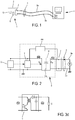
- the measurement system shown in figure 1 also comprises measuring equipment 4.
- the measuring equipment 4 is connected to the electronic measuring device 1 via the conductive pair 3.
- the measuring equipment 4 of the figure 1 has a dual function. It acquires the measurements supplied by the measuring device 1 in order to display them, record them, or analyze them. It also constitutes a source of energy making it possible to supply the measuring device 1 electrically.
- the measuring equipment 4 comprises a current source connected to the conductive pair 3, the latter supplying the measuring device 1 at constant current. At the same time, the measurement established by the electronic measuring device 1 on its output port is conveyed back by the conductive pair 3 to the measuring equipment 4 to be processed there.
- the current source typically provides a high impedance current of a few milliamps (between 2 and 20 milliamps).
- the voltage developing between the two wires of the conductive pair 3 is typically between 0V and 24 V. It is of course possible to provide that the current source is not integrated in the measuring equipment 4 but forms a separate element of the system. .
- this comprises between the transducer S providing the raw measurement of the determined quantity and the two-wire interface J, an electronic portion 5.
- This portion electrically connected to the transducer S and to the interface J, comprises a plurality of components discrete or integrated electronics (such as resistors, capacitors, inductors, transistors, amplifiers, etc.) arranged on one or a plurality of electronic cards of the PCB type.
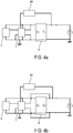
- FIG. 2 a block diagram of the electronic measuring device 1.
- the conductive pair 3 connected to a current source is electrically connected to the two-wire interface J.
- a first part of the electronic components of the electronic portion 5 constitutes a processing stage T aimed at conditioning the raw measurement supplied by the transducer S.
- This stage therefore comprises an input connected to the transducer S and an output port supplying a conditioned electrical signal.
- This output port can be electrically connected to the input or output ports of a regulator R, as will be explained in more detail in the remainder of this description.
- the conditioned electrical signal supplied by the output port of the processing stage T modulates the voltage of the output port of the measuring device 1, to convey on the conductive pair 3 an electrical voltage representative of the measured quantity .
- the conditioning of the raw measurement carried out by this processing stage T can comprise the amplification of the charges or of the voltage supplied by the transducer S and / or its filtering, for example by means of a Butterworth or Bessel filter, of Chebyshev, or any other type.
- the conditioning can be of any other nature, such as for example to provide an effective value of the raw measurement or even to include digital processing of this measurement.
- This conditioning is assisted by a feedback loop BR making it possible to inject into the processing stage T the output voltage of the measuring device 1.
- This loop can include any type of passive or active components. It can make it possible to fix or stabilize the gain and / or the idle voltage of the measuring device 1, as is well known per se.
- a regulator R for supplying voltage to the treatment stage T and / or the transducer S.
- This regulator R comprises an input port Er electrically connected to the two terminals of connection of the two-wire interface J, to which a variable voltage is therefore applied. It also includes an output port Sr supplying regulated voltage to the transducer S and / or the treatment stage T.
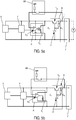
- a two-port R regulator compatible with a measuring device 1 can be realized in multiple forms.
- it may be a series regulator, therefore placed between a load C, here the processing stage T and / or the transducer S, and a variable voltage, here the voltage carried by the conductive pair 3.
- a load C here the processing stage T and / or the transducer S
- a variable voltage here the voltage carried by the conductive pair 3.
- Such a circuit causes a voltage drop between its input port and its output port, whatever the voltage present on this input port greater than the output voltage, so as to maintain constant the voltage delivered to the output port.
- the current absorbed by the input port is returned to the output port.
- Such a series regulator is shown schematically on the figure 3a in an open loop configuration, and on the figure 3b in a configuration comprising a servo-control of the regulated voltage.
- it may be a Zener diode regulator, possibly supplemented by a current source (resistor, transistor), as is shown schematically by the circuit of the figure 3c .
- a current source resistor, transistor
- the output dynamic of the measuring device 1 that is to say the possible voltage excursion between a minimum voltage and a maximum voltage, is limited. It is in fact necessary for the device to be functional that the voltage present on the output port of the measuring device 1, which also corresponds to the voltage present on the input port Er of the regulator R, remains greater than the voltage d 'food of the other elements of the device 1 increased by a drop voltage necessary for the operation of the regulator R itself.
- the voltage on the input port Er of the regulator R and therefore the voltage on the output port of the measuring device 1 , cannot drop below a minimum value of around 6V or 7V.
- the regulator R with an energy storage device Cs, for example a capacitor.
- the storage device makes it possible to store energy when the voltage on the input port Er of the regulator R is greater than the minimum threshold voltage, and to restore this energy and make it possible to maintain the regulated voltage when the voltage on the port d 'input is greater than this threshold voltage.
- the dimensioning of this storage device (for example of the capacity) and of course depending on the characteristics of the quantity measured. This solution is particularly well suited to quantities not changing at low frequency, less than 1 Hz or 10 Hz, and therefore unlikely to have a voltage lower than the threshold voltage for an extended period of time.
- the regulator R can consist of a switching regulator which can operate as a voltage step-up, shown schematically on the figure. 3d figure .
- This alternative is particularly suitable for the measurement of quasi-static quantities, such as for example the measurement of atmospheric pressure.
- the measurement of such a quantity is capable of supplying, on the output port of the device 1, a voltage lower than the threshold voltage of a series regulator for very extended periods of time. This relatively low voltage cannot therefore be easily compensated for by a storage device. having a dimension compatible with that of the measuring device 1.
- a voltage of 3 V present on the conductive pair 3 can be transformed into a voltage of 5 V on the output port Es of the regulator R thus making it possible to supply the active elements of device 1.
- a complementary circuit can be provided, supplied by the regulator R itself, to supply the chopping signal K.
- a step-up voltage regulator can also be implemented by a switched capacitor device.
- the output port of the processing stage T is electrically connected to the output port Sr of the regulator R.
- the output port of the processing stage T is electrically connected to the input port Er of the regulator R.
- the conditioned signal of the measurement available on the output port of the processing stage T modulates the voltage of the conductive pair 3 so that it is representative of the magnitude measured by the transducer S.
- the electronic portion 5 of the measuring device 1 may include other electronic components aimed at fulfilling other functions or at supplementing the functions of processing the raw measurement and of supplying a regulated supply voltage.
- the electronic measuring device 1 is therefore connected via the conductive pair 3 to a current source, which can be placed in the measuring equipment 4.
- This source supplies a nominal current, for example of a few. milliamperes, and is able to withstand a voltage range defining the dynamics of the measurement.
- This dynamic can be for example between 0 and 24 volts.
- the feedback loop BR or additional electronic components of the electronic portion 5, define the quiescent voltage supplied to the conductive pair 3 by the device 1.
- the term “quiescent voltage” denotes the voltage present on the conductive pair 3 when the determined quantity has a reference value.
- the reference value can be a pressure of 1 atm.
- the transducer S is an accelerometer, the reference value can be zero acceleration.
- the idle voltage is chosen to be greater than the regulated voltage of the supply of the transducer S and / or of the processing stage T, taking into account the waste voltage of the regulator R itself. same. If the regulator has the ability to store energy or to operate as a voltage step-up, the quiescent voltage can be chosen more freely, typically at the midpoint of the dynamic.
- the quiescent voltage is established in the pair conductor 3, at the two-wire interface J and at the input port Er of the regulator R.
- the regulator supplies the regulated supply voltage to its output port Sr to the processing stage T and / or to the transducer S which are therefore very functional.
- the variations of the measured quantity lead to varying the raw measurement supplied by the transducer S.
- the raw measurement is supplied to the input of the processing stage T in order to filter and / or amplify it.
- the output port of the processing stage T is connected to the input port Er or to the output port Sr of the regulator R in order, in all cases, to modulate the voltage present on the conductive pair 3 and make it representative of the measured quantity.
- the amplification gain of the processing stage T will be chosen to take advantage of all the possible voltage dynamics.
- the gain of the processing stage T can be adjusted to obtain a measurement sensitivity equal to or greater than 100 mV / g or 500 mV / g, where g is a unit of acceleration corresponding approximately to the acceleration of gravity on the surface of the Earth.
- a measurement dynamic of 50g is available for a sensitivity of 100 mV / g or 10g for a sensitivity of 500 mV / g.
- a rest voltage fixed at 12V we have a dynamic of 100g for a sensitivity of 100mV / g.
- the transducer S and the two-wire interface J can be a MEMS accelerometer supplied by a voltage of 5V.
- the processing stage T is here composed of a first block F for filtering the raw measurement and of a second amplification block A, electrically connected to one another in series.
- the regulator R is here composed of a series regulator, comprising a transistor Tr arranged between a conducting element of the input port Er and a conducting element of the output port Sr, and of a Zener diode Z (the characteristics of which essentially determine the voltage regulated on the output port Sr of the regulator R) placed in the base of the transistor Tr and connected to the electrical ground of the circuit.
- This electric ground is also connected to the second conductive element of the input port Er and the output port Sr of the regulator R.
- a resistor r is placed between a terminal of the transistor Tr and its base.
- a regulated voltage for example 5V, is therefore available on the output port Sr, which is distributed over the supply pins of the transducer S and of the processing stage T consisting of the filtering block F and the block d. amplification A.
- the amplification block A comprises an operational amplifier Ao supplied from the voltage supplied by the regulator R.
- This operational amplifier receives on a first differential input the raw measurement coming from the filtering block F and, on a second differential input, a voltage supplied by the feedback loop BR.
- the output of the operational amplifier Ao is connected to a transistor Ta arranged between the two conductive elements forming the output port of the amplification unit A. This port is connected to the output port Sr of the regulator R.
- the feedback loop is produced here by simple resistors, configured as a dividing bridge.
- the transistor Ta When a deviation is present on the differential input of the amplifier Ao, the transistor Ta absorbs a current on the output port Sr of the regulator R. This compensates, together with the feedback effect of the loop BR, the current absorbed by adjusting the voltage present on its Er input port. In this way, the voltage between the terminals of the two-wire interface J and conveyed on the conductive pair 3 is modulated, according to the raw measurement supplied by the transducer S.
- the figure 5b shows a second example of an electronic measuring device 1 in accordance with the first mode of implementation of the figure 4a .
- this second example only the amplification block A is modified compared to the previous example.
- the description of the other blocks or elements of the device of this second example is therefore omitted for the sake of brevity.
- the amplification block A is remarkable in that its output port, connected to the output port Sr of the regulator R, is also connected to the supply pins of the operational amplifier Ao.
- the output of the amplifier is discharged into a resistor Ra leading to an increase in the supply current of this amplifier. In this way, we consume the current present on the output port Sr of the regulator R, which compensates similar to what has been described in relation to the description of the figure 5a .
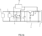
- the figure 6a shows a first example of a measuring device 1 in accordance with the second mode of implementation of the figure 4b .
- the transducer S we find the transducer S, filtering unit F, the series regulator R, and the two-wire interface J of the two preceding examples.
- the output port of amplification block A is connected to the input port Er of regulator R.
- the amplification block is identical to that of the figure 5a . In operation, with a gap present on the differential inputs of the operational amplifier, part of the current derives at the input Er of the regulator, which leads to modulating this voltage.
- the figure 6b shows a second example of a measuring device 1 in accordance with the second implementation of the figure 4b .
- the R series regulator of the previous examples has been replaced by an AC regulator.
- This is composed of a Zener Z diode arranged in series with a current source (a resistor for example).
- the output port Sr takes the voltage from the midpoint defined at the terminals of diode 2.
- the operating mode of device 1 in this example is similar to that of figure 6a .
- the figure 6c shows a variant of the first example of the second embodiment explained in relation to the description of the figure 6a .
- a storage device Cs is provided, here a capacitor whose value can typically be between 10 and 50 microFarad when the transducer is a MEMS accelerometer supplied by a voltage of 5V.
- a non-return diode D2 has also been provided so as to avoid discharging the storage device through the regulator R and the output stage of amplifier A.
- the measuring device has been presented to be supplied at constant current, the voltage being modulated to convey on the conductive pair 3 a voltage representative of the quantity measured, one could apply the same principles as those exposed to provide a device. supplied at constant voltage, and which would modulate the current flowing in the conductive pair to convey the measured quantity.
- the device may include a plurality of transducers, supplied by the regulator.
- the measurements supplied by these transducers can be combined with one another, for example to provide an average value, before being conveyed on the conductive pair.
Landscapes
- Physics & Mathematics (AREA)
- General Physics & Mathematics (AREA)
- Engineering & Computer Science (AREA)
- Power Engineering (AREA)
- Electromagnetism (AREA)
- Radar, Positioning & Navigation (AREA)
- Automation & Control Theory (AREA)
- Arrangements For Transmission Of Measured Signals (AREA)
- Measuring Fluid Pressure (AREA)
- Length Measuring Devices By Optical Means (AREA)
Claims (10)
- Elektronische Messvorrichtung (1) für eine bestimmte Größe, wobei die Vorrichtung eine Zweidrahtschnittstelle (J) mit zwei Anschlussklemmen zum Verbinden mit einem Leiterpaar (3) aufweist, das die Messvorrichtung mit Strom versorgt und in Gegenrichtung eine elektrische Größe überträgt, die für die Messgröße repräsentativ ist, die Vorrichtung umfassend:- einen Wandler (S), der eine Rohmessung der bestimmten Größe bereitstellt;- eine Verarbeitungsstufe (T) zum Konditionieren der Rohmessung, wobei die Verarbeitungsstufe einen mit dem Wandler verbundenen Eingang und einen Ausgangsanschluss umfasst;- einen Regler (R), der einen elektrisch mit den beiden Anschlussklemmen der Zweidrahtschnittstelle verbundenen Eingangsanschluss (Er) und einen den Wandler (S) und/oder die Verarbeitungsstufe (T) mit geregelter Spannung versorgenden Ausgangsanschluss (Sr) umfasst,wobei die Vorrichtung dadurch gekennzeichnet ist, dass der Ausgangsanschluss der Verarbeitungsstufe (T) mit dem Eingangsanschluss (Er) oder mit dem Ausgangsanschluss (Sr) des Reglers (R) verbunden ist und dass die Vorrichtung eine Rückkopplungsschaltung (BR) umfasst, die elektrisch mit dem Eingangsanschluss (Er) des Reglers (R) und der Verarbeitungsstufe (T) verbunden ist.
- Elektronische Messvorrichtung (1) nach dem vorhergehenden Anspruch, wobei die Verarbeitungsstufe (T) eine Filtereinheit (F) und eine Verstärkungseinheit (A) umfasst.
- Elektronische Messvorrichtung (1) nach einem der vorhergehenden Ansprüche, wobei der Regler (R) ein Serienregler ist.
- Elektronische Messvorrichtung (1) nach dem vorhergehenden Anspruch, wobei der Serienregler (R) eine Energiespeichervorrichtung umfasst.
- Elektronische Messvorrichtung (1) nach einem der Ansprüche 1 und 2, wobei der Regler (R) ein Aufwärtsregler der Spannung ist.
- Elektronische Messvorrichtung (1) nach dem vorhergehenden Anspruch, wobei der Aufwärtsregler der Spannung (R) ein Schaltregler ist.
- Elektronische Messvorrichtung (1) nach einem der vorhergehenden Ansprüche, die eingerichtet ist, mit Konstantstrom versorgt zu werden, wobei die übertragene elektrische Größe eine Spannung ist.
- Elektronische Messvorrichtung (1) nach einem der vorhergehenden Ansprüche, wobei der Wandler ein Beschleunigungsmesser ist.
- Elektronische Messvorrichtung (1) nach dem vorhergehenden Anspruch, wobei der Beschleunigungsmesser ein piezoelektrischer Beschleunigungsmesser ist.
- Elektronische Messvorrichtung (1) nach Anspruch 8, wobei der Beschleunigungsmesser ein MEMS-Beschleunigungsmesser ist.
Applications Claiming Priority (1)
| Application Number | Priority Date | Filing Date | Title |
|---|---|---|---|
| FR1854259A FR3081560B1 (fr) | 2018-05-22 | 2018-05-22 | Dispositif electronique de mesure d'une grandeur determinee presentant une interface deux fils. |
Publications (2)
| Publication Number | Publication Date |
|---|---|
| EP3572818A1 EP3572818A1 (de) | 2019-11-27 |
| EP3572818B1 true EP3572818B1 (de) | 2021-08-04 |
Family
ID=63637974
Family Applications (1)
| Application Number | Title | Priority Date | Filing Date |
|---|---|---|---|
| EP19174227.9A Active EP3572818B1 (de) | 2018-05-22 | 2019-05-13 | Elektronische vorrichtung zum messen einer bestimmten grösse, die eine zwei-draht-schnittstelle umfasst |
Country Status (4)
| Country | Link |
|---|---|
| US (1) | US11467615B2 (de) |
| EP (1) | EP3572818B1 (de) |
| CN (1) | CN110514869B (de) |
| FR (1) | FR3081560B1 (de) |
Families Citing this family (3)
| Publication number | Priority date | Publication date | Assignee | Title |
|---|---|---|---|---|
| FR3113213B1 (fr) | 2020-07-30 | 2023-03-10 | Autovib | Circuit pour fournir une tension de référence filtrée et dispositif d’alimentation exploitant un tel circuit |
| CN114414842B (zh) * | 2022-01-18 | 2023-07-04 | 厦门乃尔电子有限公司 | 一种可用于静态加速度测量的电路及测量装置 |
| CN117826691B (zh) * | 2024-03-04 | 2024-05-07 | 吉林大学 | 一种iepe兼容接口数据采集系统 |
Family Cites Families (9)
| Publication number | Priority date | Publication date | Assignee | Title |
|---|---|---|---|---|
| US3749946A (en) * | 1971-05-27 | 1973-07-31 | Ruti J Von | Elec rical circuit for the transferring and amplification of a piezoelectric transducer signal |
| US4085349A (en) * | 1976-03-12 | 1978-04-18 | Ird Mechanalysis, Inc. | Piezo electric transducer for measuring instantaneous vibration velocity |
| US4178525A (en) * | 1978-02-17 | 1979-12-11 | Robertshaw Controls Company | Two wire piezoelectric acceleration transmitter |
| US4178252A (en) * | 1978-08-31 | 1979-12-11 | Krone Ray B | Device for separating particles from a fluid suspension and method for so doing |
| KR930001165Y1 (ko) * | 1989-05-24 | 1993-03-13 | 미쓰비시덴키 가부시키가이샤 | 가속도 센서 |
| CA2347890C (en) * | 1998-11-03 | 2008-02-19 | Ametek Drexelbrook | High efficiency power supply for a two-wire loop powered device |
| DE19919084C2 (de) * | 1999-04-27 | 2001-05-31 | Micronas Gmbh | Zweidrahtsensoreinrichtung |
| US8179121B2 (en) * | 2009-03-30 | 2012-05-15 | Pcb Piezotronics, Inc. | Bridge sensor with collocated electronics and two-wire interface |
| US8786128B2 (en) * | 2010-05-11 | 2014-07-22 | Rosemount Inc. | Two-wire industrial process field device with power scavenging |
-
2018
- 2018-05-22 FR FR1854259A patent/FR3081560B1/fr active Active
-
2019
- 2019-04-18 US US16/387,740 patent/US11467615B2/en active Active
- 2019-05-13 EP EP19174227.9A patent/EP3572818B1/de active Active
- 2019-05-17 CN CN201910410783.3A patent/CN110514869B/zh active Active
Also Published As
| Publication number | Publication date |
|---|---|
| FR3081560B1 (fr) | 2020-06-05 |
| CN110514869A (zh) | 2019-11-29 |
| EP3572818A1 (de) | 2019-11-27 |
| US11467615B2 (en) | 2022-10-11 |
| FR3081560A1 (fr) | 2019-11-29 |
| US20190361473A1 (en) | 2019-11-28 |
| CN110514869B (zh) | 2023-08-04 |
Similar Documents
| Publication | Publication Date | Title |
|---|---|---|
| EP3572818B1 (de) | Elektronische vorrichtung zum messen einer bestimmten grösse, die eine zwei-draht-schnittstelle umfasst | |
| EP2343507B1 (de) | Verfahren zum kapazitiven Messen eines physikalischen Parameters und elektronischer Schnittstellenschaltkreis für einen kapazitiven Sensor | |
| EP2933224B1 (de) | Messkreis | |
| BE1023946B1 (fr) | Capteur de particules dans un fluide d'un systeme de lubrification | |
| FR3000815B1 (fr) | Regulateur d'alimentation d'un circuit integre | |
| WO2016193484A1 (fr) | Dispositif de mesure de pression à fiabilité améliorée et procédé de calibrage associé | |
| WO2016198639A1 (fr) | Dispositif de commande d'actionneur piezoelectrique | |
| FR3071318A1 (fr) | Detection de perturbations d'une tension continue | |
| FR2632793A1 (fr) | Touche perfectionnee exploitant les proprietes d'un cristal liquide | |
| EP1647091B1 (de) | Spannungsverstärker mit niedrigem verbrauch | |
| EP0910002B1 (de) | Verfahren zur Herstellung eines sehr genauen Stroms | |
| EP3696645B1 (de) | Liefervorrichtung einer stromeinspeiseleistung | |
| EP2722727B1 (de) | Zuführung einer Ladung mit Wechselpotenzial | |
| CN107534817B (zh) | 具有改进的灵敏度的mems麦克风 | |
| FR2986390A1 (fr) | Amplificateur operationnel a suppression de tension de decalage | |
| US20130156234A1 (en) | Preventing electrostatic pull-in in capacitive devices | |
| US20120326779A1 (en) | Amplifier circuit and method for conditioning an output current signal of a detector element | |
| FR2776781A1 (fr) | Dispositif de controle de l'impedance ramenee sur l'antenne d'une etiquette electromagnetique | |
| EP3451181B1 (de) | Schutzschaltkreis gegen hohe spannungen für einen usb-empfänger vom typ c | |
| FR3034862A1 (fr) | Dispositif de controle a nœuds electroniques aptes a s'alimenter electriquement entre eux et a communiquer entre eux | |
| EP0965819B1 (de) | Schnittstellenschaltungsanordnung für piezoelektrischen Sensor | |
| EP3936873B1 (de) | Industrieller triaxialer beschleunigungsaufnehmer | |
| WO2023280727A1 (fr) | Module de détection de coupure de tension d'une batterie de véhicule automobile | |
| FR2882204A1 (fr) | Circuit amplificateur large bande et circuit de polarisation | |
| EP4024708A1 (de) | Diskrete schnittstelle, die so konfiguriert ist, dass sie mindestens zwei aktive und einen inaktiven zustand in einem gerät verwaltet |
Legal Events
| Date | Code | Title | Description |
|---|---|---|---|
| PUAI | Public reference made under article 153(3) epc to a published international application that has entered the european phase |
Free format text: ORIGINAL CODE: 0009012 |
|
| STAA | Information on the status of an ep patent application or granted ep patent |
Free format text: STATUS: REQUEST FOR EXAMINATION WAS MADE |
|
| 17P | Request for examination filed |
Effective date: 20190513 |
|
| AK | Designated contracting states |
Kind code of ref document: A1 Designated state(s): AL AT BE BG CH CY CZ DE DK EE ES FI FR GB GR HR HU IE IS IT LI LT LU LV MC MK MT NL NO PL PT RO RS SE SI SK SM TR |
|
| AX | Request for extension of the european patent |
Extension state: BA ME |
|
| GRAP | Despatch of communication of intention to grant a patent |
Free format text: ORIGINAL CODE: EPIDOSNIGR1 |
|
| STAA | Information on the status of an ep patent application or granted ep patent |
Free format text: STATUS: GRANT OF PATENT IS INTENDED |
|
| INTG | Intention to grant announced |
Effective date: 20210526 |
|
| GRAS | Grant fee paid |
Free format text: ORIGINAL CODE: EPIDOSNIGR3 |
|
| GRAA | (expected) grant |
Free format text: ORIGINAL CODE: 0009210 |
|
| STAA | Information on the status of an ep patent application or granted ep patent |
Free format text: STATUS: THE PATENT HAS BEEN GRANTED |
|
| AK | Designated contracting states |
Kind code of ref document: B1 Designated state(s): AL AT BE BG CH CY CZ DE DK EE ES FI FR GB GR HR HU IE IS IT LI LT LU LV MC MK MT NL NO PL PT RO RS SE SI SK SM TR |
|
| REG | Reference to a national code |
Ref country code: GB Ref legal event code: FG4D Free format text: NOT ENGLISH |
|
| REG | Reference to a national code |
Ref country code: AT Ref legal event code: REF Ref document number: 1417496 Country of ref document: AT Kind code of ref document: T Effective date: 20210815 |
|
| REG | Reference to a national code |
Ref country code: CH Ref legal event code: EP |
|
| REG | Reference to a national code |
Ref country code: DE Ref legal event code: R096 Ref document number: 602019006533 Country of ref document: DE |
|
| REG | Reference to a national code |
Ref country code: IE Ref legal event code: FG4D Free format text: LANGUAGE OF EP DOCUMENT: FRENCH |
|
| REG | Reference to a national code |
Ref country code: LT Ref legal event code: MG9D |
|
| REG | Reference to a national code |
Ref country code: NL Ref legal event code: MP Effective date: 20210804 |
|
| REG | Reference to a national code |
Ref country code: AT Ref legal event code: MK05 Ref document number: 1417496 Country of ref document: AT Kind code of ref document: T Effective date: 20210804 |
|
| PG25 | Lapsed in a contracting state [announced via postgrant information from national office to epo] |
Ref country code: RS Free format text: LAPSE BECAUSE OF FAILURE TO SUBMIT A TRANSLATION OF THE DESCRIPTION OR TO PAY THE FEE WITHIN THE PRESCRIBED TIME-LIMIT Effective date: 20210804 Ref country code: SE Free format text: LAPSE BECAUSE OF FAILURE TO SUBMIT A TRANSLATION OF THE DESCRIPTION OR TO PAY THE FEE WITHIN THE PRESCRIBED TIME-LIMIT Effective date: 20210804 Ref country code: ES Free format text: LAPSE BECAUSE OF FAILURE TO SUBMIT A TRANSLATION OF THE DESCRIPTION OR TO PAY THE FEE WITHIN THE PRESCRIBED TIME-LIMIT Effective date: 20210804 Ref country code: FI Free format text: LAPSE BECAUSE OF FAILURE TO SUBMIT A TRANSLATION OF THE DESCRIPTION OR TO PAY THE FEE WITHIN THE PRESCRIBED TIME-LIMIT Effective date: 20210804 Ref country code: HR Free format text: LAPSE BECAUSE OF FAILURE TO SUBMIT A TRANSLATION OF THE DESCRIPTION OR TO PAY THE FEE WITHIN THE PRESCRIBED TIME-LIMIT Effective date: 20210804 Ref country code: PT Free format text: LAPSE BECAUSE OF FAILURE TO SUBMIT A TRANSLATION OF THE DESCRIPTION OR TO PAY THE FEE WITHIN THE PRESCRIBED TIME-LIMIT Effective date: 20211206 Ref country code: NO Free format text: LAPSE BECAUSE OF FAILURE TO SUBMIT A TRANSLATION OF THE DESCRIPTION OR TO PAY THE FEE WITHIN THE PRESCRIBED TIME-LIMIT Effective date: 20211104 Ref country code: BG Free format text: LAPSE BECAUSE OF FAILURE TO SUBMIT A TRANSLATION OF THE DESCRIPTION OR TO PAY THE FEE WITHIN THE PRESCRIBED TIME-LIMIT Effective date: 20211104 Ref country code: AT Free format text: LAPSE BECAUSE OF FAILURE TO SUBMIT A TRANSLATION OF THE DESCRIPTION OR TO PAY THE FEE WITHIN THE PRESCRIBED TIME-LIMIT Effective date: 20210804 Ref country code: LT Free format text: LAPSE BECAUSE OF FAILURE TO SUBMIT A TRANSLATION OF THE DESCRIPTION OR TO PAY THE FEE WITHIN THE PRESCRIBED TIME-LIMIT Effective date: 20210804 |
|
| PG25 | Lapsed in a contracting state [announced via postgrant information from national office to epo] |
Ref country code: PL Free format text: LAPSE BECAUSE OF FAILURE TO SUBMIT A TRANSLATION OF THE DESCRIPTION OR TO PAY THE FEE WITHIN THE PRESCRIBED TIME-LIMIT Effective date: 20210804 Ref country code: LV Free format text: LAPSE BECAUSE OF FAILURE TO SUBMIT A TRANSLATION OF THE DESCRIPTION OR TO PAY THE FEE WITHIN THE PRESCRIBED TIME-LIMIT Effective date: 20210804 Ref country code: GR Free format text: LAPSE BECAUSE OF FAILURE TO SUBMIT A TRANSLATION OF THE DESCRIPTION OR TO PAY THE FEE WITHIN THE PRESCRIBED TIME-LIMIT Effective date: 20211105 |
|
| PG25 | Lapsed in a contracting state [announced via postgrant information from national office to epo] |
Ref country code: NL Free format text: LAPSE BECAUSE OF FAILURE TO SUBMIT A TRANSLATION OF THE DESCRIPTION OR TO PAY THE FEE WITHIN THE PRESCRIBED TIME-LIMIT Effective date: 20210804 |
|
| PG25 | Lapsed in a contracting state [announced via postgrant information from national office to epo] |
Ref country code: DK Free format text: LAPSE BECAUSE OF FAILURE TO SUBMIT A TRANSLATION OF THE DESCRIPTION OR TO PAY THE FEE WITHIN THE PRESCRIBED TIME-LIMIT Effective date: 20210804 |
|
| REG | Reference to a national code |
Ref country code: DE Ref legal event code: R097 Ref document number: 602019006533 Country of ref document: DE |
|
| PG25 | Lapsed in a contracting state [announced via postgrant information from national office to epo] |
Ref country code: SM Free format text: LAPSE BECAUSE OF FAILURE TO SUBMIT A TRANSLATION OF THE DESCRIPTION OR TO PAY THE FEE WITHIN THE PRESCRIBED TIME-LIMIT Effective date: 20210804 Ref country code: SK Free format text: LAPSE BECAUSE OF FAILURE TO SUBMIT A TRANSLATION OF THE DESCRIPTION OR TO PAY THE FEE WITHIN THE PRESCRIBED TIME-LIMIT Effective date: 20210804 Ref country code: RO Free format text: LAPSE BECAUSE OF FAILURE TO SUBMIT A TRANSLATION OF THE DESCRIPTION OR TO PAY THE FEE WITHIN THE PRESCRIBED TIME-LIMIT Effective date: 20210804 Ref country code: EE Free format text: LAPSE BECAUSE OF FAILURE TO SUBMIT A TRANSLATION OF THE DESCRIPTION OR TO PAY THE FEE WITHIN THE PRESCRIBED TIME-LIMIT Effective date: 20210804 Ref country code: CZ Free format text: LAPSE BECAUSE OF FAILURE TO SUBMIT A TRANSLATION OF THE DESCRIPTION OR TO PAY THE FEE WITHIN THE PRESCRIBED TIME-LIMIT Effective date: 20210804 Ref country code: AL Free format text: LAPSE BECAUSE OF FAILURE TO SUBMIT A TRANSLATION OF THE DESCRIPTION OR TO PAY THE FEE WITHIN THE PRESCRIBED TIME-LIMIT Effective date: 20210804 |
|
| PLBE | No opposition filed within time limit |
Free format text: ORIGINAL CODE: 0009261 |
|
| STAA | Information on the status of an ep patent application or granted ep patent |
Free format text: STATUS: NO OPPOSITION FILED WITHIN TIME LIMIT |
|
| 26N | No opposition filed |
Effective date: 20220506 |
|
| PG25 | Lapsed in a contracting state [announced via postgrant information from national office to epo] |
Ref country code: IT Free format text: LAPSE BECAUSE OF FAILURE TO SUBMIT A TRANSLATION OF THE DESCRIPTION OR TO PAY THE FEE WITHIN THE PRESCRIBED TIME-LIMIT Effective date: 20210804 |
|
| PG25 | Lapsed in a contracting state [announced via postgrant information from national office to epo] |
Ref country code: SI Free format text: LAPSE BECAUSE OF FAILURE TO SUBMIT A TRANSLATION OF THE DESCRIPTION OR TO PAY THE FEE WITHIN THE PRESCRIBED TIME-LIMIT Effective date: 20210804 |
|
| REG | Reference to a national code |
Ref country code: BE Ref legal event code: MM Effective date: 20220531 |
|
| PG25 | Lapsed in a contracting state [announced via postgrant information from national office to epo] |
Ref country code: MC Free format text: LAPSE BECAUSE OF FAILURE TO SUBMIT A TRANSLATION OF THE DESCRIPTION OR TO PAY THE FEE WITHIN THE PRESCRIBED TIME-LIMIT Effective date: 20210804 Ref country code: LU Free format text: LAPSE BECAUSE OF NON-PAYMENT OF DUE FEES Effective date: 20220513 |
|
| PG25 | Lapsed in a contracting state [announced via postgrant information from national office to epo] |
Ref country code: IE Free format text: LAPSE BECAUSE OF NON-PAYMENT OF DUE FEES Effective date: 20220513 |
|
| PG25 | Lapsed in a contracting state [announced via postgrant information from national office to epo] |
Ref country code: BE Free format text: LAPSE BECAUSE OF NON-PAYMENT OF DUE FEES Effective date: 20220531 |
|
| PGFP | Annual fee paid to national office [announced via postgrant information from national office to epo] |
Ref country code: FR Payment date: 20230526 Year of fee payment: 5 Ref country code: DE Payment date: 20230519 Year of fee payment: 5 Ref country code: CH Payment date: 20230602 Year of fee payment: 5 |
|
| PGFP | Annual fee paid to national office [announced via postgrant information from national office to epo] |
Ref country code: GB Payment date: 20230524 Year of fee payment: 5 |
|
| PG25 | Lapsed in a contracting state [announced via postgrant information from national office to epo] |
Ref country code: HU Free format text: LAPSE BECAUSE OF FAILURE TO SUBMIT A TRANSLATION OF THE DESCRIPTION OR TO PAY THE FEE WITHIN THE PRESCRIBED TIME-LIMIT; INVALID AB INITIO Effective date: 20190513 |
|
| PG25 | Lapsed in a contracting state [announced via postgrant information from national office to epo] |
Ref country code: MK Free format text: LAPSE BECAUSE OF FAILURE TO SUBMIT A TRANSLATION OF THE DESCRIPTION OR TO PAY THE FEE WITHIN THE PRESCRIBED TIME-LIMIT Effective date: 20210804 Ref country code: CY Free format text: LAPSE BECAUSE OF FAILURE TO SUBMIT A TRANSLATION OF THE DESCRIPTION OR TO PAY THE FEE WITHIN THE PRESCRIBED TIME-LIMIT Effective date: 20210804 |