EP3572142A1 - Ship desulfurization apparatus and ship with installed ship desulfurization apparatus - Google Patents
Ship desulfurization apparatus and ship with installed ship desulfurization apparatus Download PDFInfo
- Publication number
- EP3572142A1 EP3572142A1 EP17893146.5A EP17893146A EP3572142A1 EP 3572142 A1 EP3572142 A1 EP 3572142A1 EP 17893146 A EP17893146 A EP 17893146A EP 3572142 A1 EP3572142 A1 EP 3572142A1
- Authority
- EP
- European Patent Office
- Prior art keywords
- exhaust gas
- ship
- absorber
- interior space
- body unit
- Prior art date
- Legal status (The legal status is an assumption and is not a legal conclusion. Google has not performed a legal analysis and makes no representation as to the accuracy of the status listed.)
- Pending
Links
- 238000006477 desulfuration reaction Methods 0.000 title claims abstract description 120
- 230000023556 desulfurization Effects 0.000 title claims abstract description 120
- 238000004891 communication Methods 0.000 claims abstract description 6
- 230000003009 desulfurizing effect Effects 0.000 claims abstract description 4
- 239000007789 gas Substances 0.000 claims description 221
- 239000006096 absorbing agent Substances 0.000 claims description 191
- 239000007921 spray Substances 0.000 claims description 54
- 238000005507 spraying Methods 0.000 claims description 32
- 238000004140 cleaning Methods 0.000 claims description 30
- 239000007788 liquid Substances 0.000 claims description 28
- 238000011084 recovery Methods 0.000 claims description 21
- 239000002918 waste heat Substances 0.000 claims description 21
- 238000003860 storage Methods 0.000 claims description 15
- 238000010521 absorption reaction Methods 0.000 abstract 5
- 230000000694 effects Effects 0.000 description 17
- 239000013535 sea water Substances 0.000 description 17
- FAPWRFPIFSIZLT-UHFFFAOYSA-M Sodium chloride Chemical compound [Na+].[Cl-] FAPWRFPIFSIZLT-UHFFFAOYSA-M 0.000 description 14
- 238000011156 evaluation Methods 0.000 description 13
- 238000010586 diagram Methods 0.000 description 11
- 238000005096 rolling process Methods 0.000 description 10
- XLYOFNOQVPJJNP-UHFFFAOYSA-N water Substances O XLYOFNOQVPJJNP-UHFFFAOYSA-N 0.000 description 8
- 230000007423 decrease Effects 0.000 description 7
- 239000003595 mist Substances 0.000 description 5
- 229910052717 sulfur Inorganic materials 0.000 description 5
- 239000011593 sulfur Substances 0.000 description 5
- NINIDFKCEFEMDL-UHFFFAOYSA-N Sulfur Chemical compound [S] NINIDFKCEFEMDL-UHFFFAOYSA-N 0.000 description 4
- 239000012895 dilution Substances 0.000 description 4
- 238000010790 dilution Methods 0.000 description 4
- 230000004308 accommodation Effects 0.000 description 3
- 238000009826 distribution Methods 0.000 description 3
- 239000000295 fuel oil Substances 0.000 description 3
- 229910000831 Steel Inorganic materials 0.000 description 2
- 238000005452 bending Methods 0.000 description 2
- 230000033228 biological regulation Effects 0.000 description 2
- 238000009434 installation Methods 0.000 description 2
- 238000004519 manufacturing process Methods 0.000 description 2
- 230000000414 obstructive effect Effects 0.000 description 2
- 230000001737 promoting effect Effects 0.000 description 2
- 239000000243 solution Substances 0.000 description 2
- 239000010959 steel Substances 0.000 description 2
- 150000007513 acids Chemical class 0.000 description 1
- 238000010960 commercial process Methods 0.000 description 1
- 238000013461 design Methods 0.000 description 1
- 230000005611 electricity Effects 0.000 description 1
- 239000003344 environmental pollutant Substances 0.000 description 1
- 239000000463 material Substances 0.000 description 1
- 238000000034 method Methods 0.000 description 1
- 230000004048 modification Effects 0.000 description 1
- 238000012986 modification Methods 0.000 description 1
- 238000012856 packing Methods 0.000 description 1
- 231100000719 pollutant Toxicity 0.000 description 1
- 230000002787 reinforcement Effects 0.000 description 1
Images


Classifications
-
- F—MECHANICAL ENGINEERING; LIGHTING; HEATING; WEAPONS; BLASTING
- F01—MACHINES OR ENGINES IN GENERAL; ENGINE PLANTS IN GENERAL; STEAM ENGINES
- F01N—GAS-FLOW SILENCERS OR EXHAUST APPARATUS FOR MACHINES OR ENGINES IN GENERAL; GAS-FLOW SILENCERS OR EXHAUST APPARATUS FOR INTERNAL COMBUSTION ENGINES
- F01N3/00—Exhaust or silencing apparatus having means for purifying, rendering innocuous, or otherwise treating exhaust
- F01N3/08—Exhaust or silencing apparatus having means for purifying, rendering innocuous, or otherwise treating exhaust for rendering innocuous
- F01N3/0807—Exhaust or silencing apparatus having means for purifying, rendering innocuous, or otherwise treating exhaust for rendering innocuous by using absorbents or adsorbents
- F01N3/0828—Exhaust or silencing apparatus having means for purifying, rendering innocuous, or otherwise treating exhaust for rendering innocuous by using absorbents or adsorbents characterised by the absorbed or adsorbed substances
- F01N3/085—Sulfur or sulfur oxides
-
- B—PERFORMING OPERATIONS; TRANSPORTING
- B01—PHYSICAL OR CHEMICAL PROCESSES OR APPARATUS IN GENERAL
- B01D—SEPARATION
- B01D53/00—Separation of gases or vapours; Recovering vapours of volatile solvents from gases; Chemical or biological purification of waste gases, e.g. engine exhaust gases, smoke, fumes, flue gases, aerosols
- B01D53/34—Chemical or biological purification of waste gases
- B01D53/46—Removing components of defined structure
- B01D53/48—Sulfur compounds
- B01D53/50—Sulfur oxides
- B01D53/501—Sulfur oxides by treating the gases with a solution or a suspension of an alkali or earth-alkali or ammonium compound
- B01D53/504—Sulfur oxides by treating the gases with a solution or a suspension of an alkali or earth-alkali or ammonium compound characterised by a specific device
-
- B—PERFORMING OPERATIONS; TRANSPORTING
- B01—PHYSICAL OR CHEMICAL PROCESSES OR APPARATUS IN GENERAL
- B01D—SEPARATION
- B01D53/00—Separation of gases or vapours; Recovering vapours of volatile solvents from gases; Chemical or biological purification of waste gases, e.g. engine exhaust gases, smoke, fumes, flue gases, aerosols
- B01D53/14—Separation of gases or vapours; Recovering vapours of volatile solvents from gases; Chemical or biological purification of waste gases, e.g. engine exhaust gases, smoke, fumes, flue gases, aerosols by absorption
- B01D53/1456—Removing acid components
-
- B—PERFORMING OPERATIONS; TRANSPORTING
- B01—PHYSICAL OR CHEMICAL PROCESSES OR APPARATUS IN GENERAL
- B01D—SEPARATION
- B01D53/00—Separation of gases or vapours; Recovering vapours of volatile solvents from gases; Chemical or biological purification of waste gases, e.g. engine exhaust gases, smoke, fumes, flue gases, aerosols
- B01D53/14—Separation of gases or vapours; Recovering vapours of volatile solvents from gases; Chemical or biological purification of waste gases, e.g. engine exhaust gases, smoke, fumes, flue gases, aerosols by absorption
- B01D53/18—Absorbing units; Liquid distributors therefor
-
- B—PERFORMING OPERATIONS; TRANSPORTING
- B63—SHIPS OR OTHER WATERBORNE VESSELS; RELATED EQUIPMENT
- B63B—SHIPS OR OTHER WATERBORNE VESSELS; EQUIPMENT FOR SHIPPING
- B63B25/00—Load-accommodating arrangements, e.g. stowing, trimming; Vessels characterised thereby
-
- B—PERFORMING OPERATIONS; TRANSPORTING
- B63—SHIPS OR OTHER WATERBORNE VESSELS; RELATED EQUIPMENT
- B63H—MARINE PROPULSION OR STEERING
- B63H21/00—Use of propulsion power plant or units on vessels
- B63H21/12—Use of propulsion power plant or units on vessels the vessels being motor-driven
- B63H21/14—Use of propulsion power plant or units on vessels the vessels being motor-driven relating to internal-combustion engines
-
- B—PERFORMING OPERATIONS; TRANSPORTING
- B63—SHIPS OR OTHER WATERBORNE VESSELS; RELATED EQUIPMENT
- B63H—MARINE PROPULSION OR STEERING
- B63H21/00—Use of propulsion power plant or units on vessels
- B63H21/32—Arrangements of propulsion power-unit exhaust uptakes; Funnels peculiar to vessels
-
- B—PERFORMING OPERATIONS; TRANSPORTING
- B63—SHIPS OR OTHER WATERBORNE VESSELS; RELATED EQUIPMENT
- B63J—AUXILIARIES ON VESSELS
- B63J3/00—Driving of auxiliaries
- B63J3/02—Driving of auxiliaries from propulsion power plant
-
- F—MECHANICAL ENGINEERING; LIGHTING; HEATING; WEAPONS; BLASTING
- F01—MACHINES OR ENGINES IN GENERAL; ENGINE PLANTS IN GENERAL; STEAM ENGINES
- F01N—GAS-FLOW SILENCERS OR EXHAUST APPARATUS FOR MACHINES OR ENGINES IN GENERAL; GAS-FLOW SILENCERS OR EXHAUST APPARATUS FOR INTERNAL COMBUSTION ENGINES
- F01N13/00—Exhaust or silencing apparatus characterised by constructional features ; Exhaust or silencing apparatus, or parts thereof, having pertinent characteristics not provided for in, or of interest apart from, groups F01N1/00 - F01N5/00, F01N9/00, F01N11/00
- F01N13/004—Exhaust or silencing apparatus characterised by constructional features ; Exhaust or silencing apparatus, or parts thereof, having pertinent characteristics not provided for in, or of interest apart from, groups F01N1/00 - F01N5/00, F01N9/00, F01N11/00 specially adapted for marine propulsion, i.e. for receiving simultaneously engine exhaust gases and engine cooling water
-
- F—MECHANICAL ENGINEERING; LIGHTING; HEATING; WEAPONS; BLASTING
- F01—MACHINES OR ENGINES IN GENERAL; ENGINE PLANTS IN GENERAL; STEAM ENGINES
- F01N—GAS-FLOW SILENCERS OR EXHAUST APPARATUS FOR MACHINES OR ENGINES IN GENERAL; GAS-FLOW SILENCERS OR EXHAUST APPARATUS FOR INTERNAL COMBUSTION ENGINES
- F01N3/00—Exhaust or silencing apparatus having means for purifying, rendering innocuous, or otherwise treating exhaust
- F01N3/02—Exhaust or silencing apparatus having means for purifying, rendering innocuous, or otherwise treating exhaust for cooling, or for removing solid constituents of, exhaust
- F01N3/04—Exhaust or silencing apparatus having means for purifying, rendering innocuous, or otherwise treating exhaust for cooling, or for removing solid constituents of, exhaust using liquids
-
- F—MECHANICAL ENGINEERING; LIGHTING; HEATING; WEAPONS; BLASTING
- F01—MACHINES OR ENGINES IN GENERAL; ENGINE PLANTS IN GENERAL; STEAM ENGINES
- F01N—GAS-FLOW SILENCERS OR EXHAUST APPARATUS FOR MACHINES OR ENGINES IN GENERAL; GAS-FLOW SILENCERS OR EXHAUST APPARATUS FOR INTERNAL COMBUSTION ENGINES
- F01N3/00—Exhaust or silencing apparatus having means for purifying, rendering innocuous, or otherwise treating exhaust
- F01N3/08—Exhaust or silencing apparatus having means for purifying, rendering innocuous, or otherwise treating exhaust for rendering innocuous
- F01N3/10—Exhaust or silencing apparatus having means for purifying, rendering innocuous, or otherwise treating exhaust for rendering innocuous by thermal or catalytic conversion of noxious components of exhaust
- F01N3/24—Exhaust or silencing apparatus having means for purifying, rendering innocuous, or otherwise treating exhaust for rendering innocuous by thermal or catalytic conversion of noxious components of exhaust characterised by constructional aspects of converting apparatus
- F01N3/28—Construction of catalytic reactors
-
- F—MECHANICAL ENGINEERING; LIGHTING; HEATING; WEAPONS; BLASTING
- F01—MACHINES OR ENGINES IN GENERAL; ENGINE PLANTS IN GENERAL; STEAM ENGINES
- F01N—GAS-FLOW SILENCERS OR EXHAUST APPARATUS FOR MACHINES OR ENGINES IN GENERAL; GAS-FLOW SILENCERS OR EXHAUST APPARATUS FOR INTERNAL COMBUSTION ENGINES
- F01N5/00—Exhaust or silencing apparatus combined or associated with devices profiting by exhaust energy
- F01N5/02—Exhaust or silencing apparatus combined or associated with devices profiting by exhaust energy the devices using heat
-
- F—MECHANICAL ENGINEERING; LIGHTING; HEATING; WEAPONS; BLASTING
- F02—COMBUSTION ENGINES; HOT-GAS OR COMBUSTION-PRODUCT ENGINE PLANTS
- F02G—HOT GAS OR COMBUSTION-PRODUCT POSITIVE-DISPLACEMENT ENGINE PLANTS; USE OF WASTE HEAT OF COMBUSTION ENGINES; NOT OTHERWISE PROVIDED FOR
- F02G5/00—Profiting from waste heat of combustion engines, not otherwise provided for
- F02G5/02—Profiting from waste heat of exhaust gases
-
- B—PERFORMING OPERATIONS; TRANSPORTING
- B01—PHYSICAL OR CHEMICAL PROCESSES OR APPARATUS IN GENERAL
- B01D—SEPARATION
- B01D2252/00—Absorbents, i.e. solvents and liquid materials for gas absorption
- B01D2252/10—Inorganic absorbents
- B01D2252/103—Water
- B01D2252/1035—Sea water
-
- B—PERFORMING OPERATIONS; TRANSPORTING
- B01—PHYSICAL OR CHEMICAL PROCESSES OR APPARATUS IN GENERAL
- B01D—SEPARATION
- B01D2258/00—Sources of waste gases
- B01D2258/01—Engine exhaust gases
- B01D2258/012—Diesel engines and lean burn gasoline engines
-
- B—PERFORMING OPERATIONS; TRANSPORTING
- B01—PHYSICAL OR CHEMICAL PROCESSES OR APPARATUS IN GENERAL
- B01D—SEPARATION
- B01D2259/00—Type of treatment
- B01D2259/45—Gas separation or purification devices adapted for specific applications
- B01D2259/4566—Gas separation or purification devices adapted for specific applications for use in transportation means
-
- B—PERFORMING OPERATIONS; TRANSPORTING
- B01—PHYSICAL OR CHEMICAL PROCESSES OR APPARATUS IN GENERAL
- B01D—SEPARATION
- B01D53/00—Separation of gases or vapours; Recovering vapours of volatile solvents from gases; Chemical or biological purification of waste gases, e.g. engine exhaust gases, smoke, fumes, flue gases, aerosols
- B01D53/14—Separation of gases or vapours; Recovering vapours of volatile solvents from gases; Chemical or biological purification of waste gases, e.g. engine exhaust gases, smoke, fumes, flue gases, aerosols by absorption
- B01D53/1456—Removing acid components
- B01D53/1481—Removing sulfur dioxide or sulfur trioxide
-
- F—MECHANICAL ENGINEERING; LIGHTING; HEATING; WEAPONS; BLASTING
- F01—MACHINES OR ENGINES IN GENERAL; ENGINE PLANTS IN GENERAL; STEAM ENGINES
- F01N—GAS-FLOW SILENCERS OR EXHAUST APPARATUS FOR MACHINES OR ENGINES IN GENERAL; GAS-FLOW SILENCERS OR EXHAUST APPARATUS FOR INTERNAL COMBUSTION ENGINES
- F01N2590/00—Exhaust or silencing apparatus adapted to particular use, e.g. for military applications, airplanes, submarines
- F01N2590/02—Exhaust or silencing apparatus adapted to particular use, e.g. for military applications, airplanes, submarines for marine vessels or naval applications
-
- F—MECHANICAL ENGINEERING; LIGHTING; HEATING; WEAPONS; BLASTING
- F01—MACHINES OR ENGINES IN GENERAL; ENGINE PLANTS IN GENERAL; STEAM ENGINES
- F01N—GAS-FLOW SILENCERS OR EXHAUST APPARATUS FOR MACHINES OR ENGINES IN GENERAL; GAS-FLOW SILENCERS OR EXHAUST APPARATUS FOR INTERNAL COMBUSTION ENGINES
- F01N2610/00—Adding substances to exhaust gases
- F01N2610/14—Arrangements for the supply of substances, e.g. conduits
- F01N2610/1453—Sprayers or atomisers; Arrangement thereof in the exhaust apparatus
Definitions
- the present disclosure relates to a ship desulfurization device and a ship equipped with the ship desulfurization device.
- the amount of exhaust gas discharged from a main engine of a super-large size ship (exhaust gas amount at the time of 100% load) reaches as much as 200,000 Nm 3 /h, or even more.
- a super-large size ship is equipped with a plurality of generator engines and boilers.
- a desulfurization device to be mounted to a super-large size ship needs to have an absorber having a broad area for passage, to desulfurize a large volume of exhaust gas discharged from the main engine and the plurality of generator engines and boilers.
- a typical desulfurization device for a relatively small main engine is equipped with a round (circular) absorber.
- a round absorber tends to involve dead space when placed in a ship, as compared to a rectangular absorber, and thus may deteriorate the layout efficiency in a ship.
- a rectangular absorber may be provided, which is a proven absorber that has been used in onshore desulfurization devices for plant facilities, factories, and the like.
- Patent Document 1 discloses an example of cleaning device provided with a rectangular cleaning tank (absorber), which is a wet-type cleaning device for removing pollutants such as particulate matters, harmful gases, acidic compounds, and foul odor, from a production process, an industrial process, a commercial process, or the like.
- the rectangular absorbers used in onshore desulfurization devices have a length L in the exhaust gas introducing direction in the interior space of the absorber and a length W in a direction orthogonal to the exhaust gas introducing direction, which satisfy a ratio (W:L) of from 1:0.2 to 1:1.0.
- the absorber in a planar view, has a rectangular shape with a lateral (shorter) direction along the exhaust gas introducing direction, and a longitudinal (longer) direction along a direction orthogonal to the exhaust gas introducing direction.
- the cleaning device of the Patent Document 1 described above has an exhaust gas introducing port on an upper end portion of the absorber, and is configured to introduce exhaust gas introduced from the exhaust gas introducing port into a gas distribution chamber disposed on a lower part of the absorber via an exhaust gas duct extending vertically in the absorber, so as to let exhaust gas flow uniformly through the absorber.
- an absorber having a longitudinal direction along the exhaust gas introducing direction in a planar view may have a higher arrangement performance.
- the cleaning tank disclosed in Patent Document 1 includes an exhaust gas duct extending vertically in the absorber, and a gas distribution chamber disposed on a lower part of the cleaning tank.
- the volume of the absorber is increased as much as the space required to provide the exhaust gas duct and the gas distribution chamber.
- the main engine which is a main source that discharges exhaust gas
- the absorber is normally disposed above the main engine in the hull.
- Patent Document 2 discloses a desulfurization device having a rectangular absorber mounted to a ship ( FIGs. 3 and 4 ).
- the absorber of Patent Document 2 is mounted to a barge towed by a tanker (main ship), not to the main ship itself, and there is no disclosure of the problem related to layout limitations in arranging a desulfurization device on a ship (main ship), or solution thereto.
- the present invention was made under the above described background art, and the object thereof is to provide a ship desulfurization device which has a high arrangement performance in a ship such as a super-large size ship.
- a ship desulfurization device having a high arrangement performance, for a ship being a super-large size container ship or the like as described above.
- an expression of relative or absolute arrangement such as “in a direction”, “along a direction”, “parallel”, “orthogonal”, “centered”, “concentric” and “coaxial” shall not be construed as indicating only the arrangement in a strict literal sense, but also includes a state where the arrangement is relatively displaced by a tolerance, or by an angle or a distance whereby it is possible to achieve the same function.
- an expression of an equal state such as “same” “equal” and “uniform” shall not be construed as indicating only the state in which the feature is strictly equal, but also includes a state in which there is a tolerance or a difference that can still achieve the same function.
- an expression of a shape such as a rectangular shape or a cylindrical shape shall not be construed as only the geometrically strict shape, but also includes a shape with unevenness or chamfered corners within the range in which the same effect can be achieved.
- FIG. 1 is a perspective view of a ship according to an embodiment of the present invention.
- the ship 1 according to an embodiment of the present invention is a super-large size ship which includes a main engine whose exhaust gas amount (exhaust gas amount at the time of 100% load) exceeds 200,000Nm 3 /h.
- the ship 1 is a super-large size container ship having a container load capacity of at least 10,000 TEU, known as an ultra large container ship (ULCS).
- ULCS ultra large container ship
- the ship 1 includes a hull 2, an accommodation house 4 protruding from an upper deck 3 at a position slightly closer to the front from the center with respect to the fore-aft direction, and a funnel 6 protruding from the upper deck 3 at a position closer to the stern from the accommodation house 4.
- a plurality of bulkheads 8 are provided at intervals from one another, extending in the starboard-port direction orthogonal to the fore-aft direction. Accordingly, in the fore-aft direction, the hull 2 is divided into a plurality of regions, whose basic unit is a length capable of accommodating a 40-feet container 9 along the longitudinal direction of the container.
- FIG. 2A shows the dimensions of the 40-feet container 9.
- FIG. 2B is an enlarged view of a funnel and its surroundings in the ship shown in FIG. 2B .
- the funnel 6 is disposed between a pair of adjacent bulkheads 8A, 8B.
- An engine room 10 is formed inside the hull 2, directly below the funnel 6.
- a main engine 12 and a plurality of auxiliary engines 14 are disposed in the engine room 10.
- the main engine 12 includes a marine diesel engine for applying a propelling force to the ship 1, or a main engine boiler for driving a main engine turbine.
- the auxiliary engines 14 include auxiliary boilers and auxiliary engines for meeting various heat demands in the ship 1.
- the main engine 12 and the auxiliary engines 14 correspond to an exhaust gas generation device mounted to the ship 1 according to an embodiment of the present invention.
- the funnel 6 is a structure for releasing exhaust gas discharged from the main engine 12 and the auxiliary engines 14 to outside of the ship 1, and is formed to have an elongated tubular shape having a longitudinal direction along the starboard-port direction (width direction) of the ship 1. Further, inside the funnel 6, a ship desulfurization device 20 is disposed, for desulfurizing exhaust gas discharged from the main engine 12 and the auxiliary engines 14 mounted to the ship 1.
- the inner width of the funnel 6 (length in a direction orthogonal to the longitudinal direction) is within a range from about 3m to 8m.
- the length in the longitudinal direction of the funnel 6 has relatively fewer limitations, and may be set within a range from 5m to 20m, for instance.
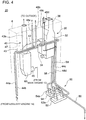
- FIG. 3 is a perspective view of a ship desulfurization device according to an embodiment of the present invention.
- FIG. 4 is a perspective view of a ship desulfurization device according to an embodiment of the present invention, as seen in a different direction from FIG. 3 .
- the ship desulfurization device 20 includes an absorber 30 including an absorber body unit 32, and an exhaust gas introducing device 40 for guiding exhaust gas discharged from the main engine 12 and the auxiliary engines 14 to the absorber body unit 32.
- FIG. 5 is a schematic diagram of an absorber of a ship desulfurization device according to an embodiment of the present invention.
- the absorber 30 includes an absorber body unit 32, an exhaust gas introducing unit 34, and an exhaust gas discharge unit 36.
- the absorber body unit 32 defines an interior space 31 having a longitudinal direction therein.
- an exhaust gas introducing port 33 is formed and is in communication with the interior space 31 (lower interior space 31b). Exhaust gas introduced into the interior space 31 through the exhaust gas introducing port 33 flows through the lower interior space 31b from the lateral end portion 39a on the first side toward the lateral end portion 39b on the second side, and continues flowing upward through the interior space 31.
- a packed layer 35 separating the lower interior space 31b and the upper interior space 31c is formed, in a position above the lower interior space 31b.
- the packed layer 35 includes a plurality of regular packings laminated into several layers.
- a spraying device 38 is disposed, for spraying a cleaning liquid (e.g. sea water or pure water) into the interior space.
- the spraying device 38 is configured to remove sulfur from exhaust gas by spraying the cleaning liquid over exhaust gas passing through the packed layer 35 and causing gas-liquid contact between exhaust gas and the cleaning liquid.
- a mist eliminator 37 separating the upper interior space 31c and the outlet-side interior space 31d is disposed, in a position above the upper interior space 31c.
- the mist eliminator 37 is configured to remove moisture from exhaust gas passing through the mist eliminator 37. Further, exhaust gas having passed through the mist eliminator 37 is discharged outside the ship 1 from the exhaust gas discharge unit 36 connected to the top section of the absorber body unit 32, via the outlet-side interior space 31d.
- a storage space 31a storing a cleaning liquid after being sprayed over exhaust gas introduced into the interior space 31 is formed in the absorber body unit 32.
- the storage space 31a is formed on a position below the lower interior space 31b, and below the lower surface of the exhaust gas introducing port 33.
- the ship desulfurization device 20 further includes a sea-water supplying device 50 for suppling sea water to the above described spraying device 38.
- the sea-water supplying device 50 includes a discharged water dilution pump 52a, a sea-water supply pump 54a, a discharge water pipe 56, a sea-water supply pipe 58, and a sea-water discharge pipe 59. Further, the sea-water supplying device 50 is configured to supply sea water introduced into the hull 2 with the sea-water supply pump 54a to the spraying device 38 via the sea-water supply pipe 58.
- the sea-water supplying device 50 is configured to dilute scrubber discharge water discharged from the absorber 30 with the dilution pump 52a, and discharge the water outside the ship 1 via the discharge water pipe 56. Further, in the depicted embodiment, each of a plurality of discharged water dilution pumps 52a is connected to the same No.1 sea chest 52. Similarly, each of a plurality of sea-water supply pumps 54a is connected to the same No.2 sea chest 54.
- the interior space 31 of the absorber body unit 32 is formed to have a planar shape that has a longitudinal direction along the exhaust gas introducing direction.
- the planar shape of the interior space 31 of the absorber body unit 32 will now be described in detail with reference to FIG. 6 .
- reference sign L indicates the length of the interior space 31 (length in the longitudinal direction)
- reference sign W indicates the width of the interior space 31 (length in a direction orthogonal to the longitudinal direction).
- reference sign D indicates the equivalent diameter, which is a diameter of a circular cross-section that has the same cross-sectional area as that of a rectangular having the length L and the width W.
- the planar shape of the interior space 31 of the absorber body unit 32 has a rectangular shape defined by a pair of longitudinal wall surfaces extending parallel to each other and a pair of lateral wall surfaces extending parallel to each other.
- the planar shape of the interior space 31 is not limited to a rectangular shape, and may be a quadrilateral shape, an oval shape, or an ellipse shape having a longitudinal direction, as long as the effect of the present invention can be achieved.
- FIG. 6 is a diagram showing a result of a study on the planar shape of the interior space of the absorber body unit in a ship desulfurization device according to an embodiment of the present invention.
- each planar shape is evaluated according to two items: "arrangement performance" refers to how easily the absorber 30 can be arranged in the ship 1 in terms of layout, and “desulfurization performance” refers to how uniform the exhaust gas flows through the interior space 31 in the absorber 30.
- the "arrangement performance” was evaluated on the basis of the following evaluation criteria, in four stages of A, B, C, and D, which represent the arrangement performance in the descending order. This evaluation is based on the idea that, when the absorber 30 is to be placed in an area having an elongated shape such as the inside of the funnel 6, the smaller maximum width W in the lateral direction relative to the equivalent diameter D, the higher the arrangement performance.
- FIG. 9 is a graph showing a relationship between a desulfurization performance parameter and the shape (aspect ratio L/W) of the interior space of the absorber in a ship desulfurization device according to an embodiment of the present invention.
- the data is expressed in double logarithm in order to make its change stand out.
- FIG. 10 is a diagram showing a result of a study on the relationship between a desulfurization performance parameter and the shape (aspect ratio) of the interior space of the absorber body unit in a ship desulfurization device according to an embodiment of the present invention.
- FIG. 11 is a planar view for describing the arrangement condition of a spray nozzle in the interior space of the absorber body unit.
- Desulfurization performance parameter perimeter ratio ⁇ ⁇ interference nozzle number ratio ⁇
- An interference nozzle refers to a spray nozzle which is surrounded by other spray nozzles on four sides. That is, as shown in FIG. 11 , in a case where a plurality of rows of spray nozzles 70 are disposed along the longitudinal direction and the width direction in the interior space 31 of the absorber body unit 32, such that a plurality of spray nozzles 70 are arranged in a grid pattern as a whole, the spray nozzles 70b disposed inside the range 70A excluding the spray nozzles 70a disposed on the outermost side are the above described interference nozzles.
- the desulfurization performance parameter decreases. From FIG. 9 , the desulfurization performance parameter is substantially constant when L/W is 2.0 or below, decreases in the range from 2.0 to 6.0, and decreases considerably when L/W is 6.0 or higher. Thus, it was determined that there are two inflection points at L/W 2.0 and 6.0.
- the "desulfurization performance” was evaluated on the basis of the following evaluation criteria, in four stages of A, B, C, and D, which represents the desulfurization performance in the descending order. This is based on the idea that, the more uniform the exhaust gas flows through the absorber 30, the higher the desulfurization performance. Further, the uniformity of the exhaust gas flow inside the absorber 30 was evaluated from the above study results on the basis of the following study conditions. As shown in FIG. 9 , when the aspect ratio is two or lower, it is possible to maintain the desulfurization performance parameter at a substantially constant high level, and it is possible to maintain the uniformity of the exhaust gas flow in the absorber 30 in a preferable state.
- the aspect ratio when the aspect ratio is greater than two and not greater than three, the desulfurization performance gradually decreases with an increase in the aspect ratio, but the desulfurization performance parameter can be maintained at a high level. Further, also when the aspect ratio is greater than three and not greater than six, the desulfurization performance gradually decreases with an increase in the aspect ratio, but still the desulfurization performance parameter can be maintained at a relatively high level.
- the aspect ratio when the aspect ratio exceeds six, the desulfurization parameter decreases rapidly, and the uniformity of the exhaust gas in the absorber 30 can be considered to get out of the allowable range for exerting the required desulfurization performance. Accordingly, the aspect ratio was set to have an upper limit of six.
- the planar shape of the interior space 31 where W:L is 1: over 1.5 and 1:2.0 or under 2.0 was evaluated as "excellent” in the comprehensive evaluation. While “arrangement performance” and “desulfurization performance” have a trade-off relationship, by setting W:L in the above range, it is possible to provide a ship desulfurization device 20 with a good balance, which excels in both of the arrangement performance and the desulfurization performance.
- planar shape of the interior space 31 where W:L is 1: over 2.0 and 1:3.0 or under 3.0 was evaluated as "good” in the comprehensive evaluation.
- planar shape of the interior space 31 where W:L is 1: over 3.0 and 1:6.0 or under 6.0 was evaluated as "passable" in the comprehensive evaluation.
- planar shape of the interior space 31 where W:L is 1:1.1 or under 1.1 was evaluated as “fail”, for the “arrangement performance” is low, although the “desulfurization performance” is high. Furthermore, as described above, the planar shape of the interior space 31 where W:L is 1: over 6.0 was evaluated as “fail”, for the uniformity of the exhaust gas flow in the absorber 30 cannot be ensured, and the "desulfurization performance" is low.
- the ship desulfurization device 20 includes the absorber 30 including the absorber body unit 32 defining the interior space 31 having the longitudinal direction and having the exhaust gas introducing port 33 formed on the lateral end portion 39a on the first side in the longitudinal direction so as to be in communication with the interior space 31 (lower interior space 31b). That is, the interior space 31 of the absorber body unit 32 is formed to have a longitudinal direction along the exhaust gas introducing direction. Thus, dead space is less likely to be formed as compared to a typical round (circular) absorber, and thus the arrangement performance is high when being provided for the ship 1.
- the absorber 30 having a planar shape with a longitudinal direction along the exhaust gas introducing direction, it is possible to improve the arrangement performance of the ship desulfurization device 20, for the ship 1 being a super-large size container ship or the like as described above. Furthermore, compared to a case in which the interior space of the absorber body unit has a longitudinal direction along a direction orthogonal to the exhaust gas introducing direction, it is possible to reduce the risk of exhaust gas being discharged outside of the absorber without being desulfurized.
- the ratio (W:L) of the maximum width W to the maximum length L of the interior space 31 is within the range of 1: over 1 and 1:6.0 or under 6.0. Accordingly, by setting the upper limit of 1:6.0 for the ratio (W:L) of the maximum width W to the maximum length L of the interior space 31, it is possible to keep the unevenness of the exhaust gas flow in the absorber 30 within the practically allowable range according to the study of the present inventors.
- the ratio (W:L) of the maximum width W to the maximum length L of the interior space 31 is within the range of 1: over 1.5 and 1:2.0 or under 2.0.
- the absorber 30 is mounted to the ship 1 so that the longitudinal direction of the interior space 31 of the absorber body unit 32 is along the width direction of the ship 1.
- the absorber 30 having the longitudinal direction along the width direction of the ship 1, it is possible to improve the arrangement performance of the ship desulfurization device 20, for the ship 1 being a super-large size container ship or the like as described above.
- the absorber body unit 32 it is possible to configure the absorber body unit 32 so as to have the longitudinal direction along the width direction of the ship 1, and thus it is possible to reduce bending stress applied to the absorber at the time of rolling of the ship 1, as compared to an absorber having the longitudinal direction along the fore-aft direction of the ship 1. Thus, it is possible to enhance the resistance of the absorber 30 against rolling.
- the ship 1 includes the funnel 6 for releasing exhaust gas discharged from the exhaust gas generation device (the main engine 12 and the auxiliary engines 14) to outside of the ship 1, formed to have an elongated tubular shape having a longitudinal direction along the width direction of the ship 1. Further, the absorber 30 is disposed inside the funnel 6.
- the planar shape of the funnel 6 is formed into a rectangular shape. Further, in some embodiments, the planar shape of the funnel 6 is formed into a quadrilateral shape, an oval shape, an ellipse shape, or the like, having a longitudinal direction.
- the absorber 30 positioned inside the funnel 6 having an elongated tubular shape having the longitudinal direction along the width direction of the ship 1 it is possible to minimize the influence on the arrangement plan of various facilities to be mounted to the ship 1 other than the absorber 30.
- an existing ship 1 can be easily retrofitted.
- the absorber 30 disposed inside the funnel 6 it is possible to improve the installation workability and maintainability, compared to a case in which the absorber 30 is disposed inside the ship 1, like inside the engine room 10.
- an waste heat recovery device 60 for recovering thermal energy from exhaust gas discharged from the exhaust gas generation device (main engine 12) is disposed inside the funnel 6 described above. Further, the absorber 30 is disposed next to the waste heat recovery device 60 in the width direction of the waste heat recovery device 60.
- the waste heat recovery device 60 includes an exhaust gas economizer configured to generate steam from thermal energy recovered from exhaust gas.
- the above exhaust gas inlet pipe 45, the exhaust gas discharge pipe 43, the exhaust gas introducing pipe 42 form a part of the exhaust gas introducing device 40 described above for introducing exhaust gas discharged from the main engine 12 and the auxiliary engines 14 to the absorber body unit 32.
- the waste heat recovery device 60 is formed to have a longitudinal direction along the width direction of the ship 1. Further, the interior space of the waste heat recovery device 60 has a rectangular cross sectional shape.
- the absorber 30 and the waste heat recovery device 60 being arranged next to each other along the width direction of the ship 1 inside the funnel 6, it is possible to simplify the configuration of the exhaust gas introducing device 40, compared to a case in which the waste heat recovery device 60 and the absorber 30 are disposed away from each other. Further, since the waste heat recovery device 60 is formed to have a rectangular shape with the longitudinal direction along the width direction of the ship 1, dead space is less likely to be formed inside the funnel 5 having the longitudinal direction along the width direction of the ship 1, and thus the arrangement efficiency is improved.
- the absorber 30 may further include an exhaust gas introducing unit 34 having a first end portion 34a connected to the exhaust gas introducing port 33 of the absorber body unit 32, and extending upward from the first end portion 34a toward the second end portion 34b.
- the exhaust gas introducing unit 34 has a quadrilateral cross sectional shape, and so does the exhaust gas introducing port 33. Further, the exhaust gas introducing unit 34 includes an oblique portion 34A extending obliquely upward from the exhaust gas introducing port 33 of the absorber body unit 32, and a vertical portion 34B extending upward along the vertical direction from an end portion of the oblique portion 34A. Further, to an end portion of the vertical portion 34B (the second end portion 34b of the exhaust gas introducing unit 34), the exhaust gas introducing pipe 42 described below is connected.
- the above described exhaust gas introducing device 40 includes an exhaust gas introducing pipe 42 extending along the width direction of the ship 1 from the waste heat recovery device 60 toward the second end portion 34b of the exhaust gas introducing unit 34, and auxiliary exhaust gas introducing pipes 44a to 44d connected to the exhaust gas introducing pipe 42, for introducing exhaust gas discharged from the auxiliary engines 14 to the absorber body unit 32 via the exhaust gas introducing pipe 42.
- an end side of the exhaust gas introducing pipe 42 is connected to the exhaust gas discharge pipe 4 described above, and the other end side is connected to the second end portion 34b of the exhaust gas introducing unit 34 described above. Further, the exhaust gas introducing pipe 42 extends along the horizontal direction inside the funnel 6.
- an exhaust gas outlet pipe 46 extending upward inside the funnel 6 and the exhaust gas introducing pipe 42 are connected to the downstream side of the exhaust gas discharge pipe 43, via an exhaust gas damper 47. Further, when the exhaust gas generation device such as the main engine 12 and the auxiliary engines 14 is stopped, the exhaust gas damper 47 opens a flow path connecting to the exhaust gas outlet pipe 46 from the exhaust gas discharge pipe 43, and closes a flow path connecting to the exhaust gas introducing pipe 42 from the exhaust gas discharge pipe 43.
- the exhaust gas damper 47 opens a flow path connecting to the exhaust gas introducing pipe 42 from the exhaust gas discharge pipe 43, and closes a flow path connecting to the exhaust gas outlet pipe 46 from the exhaust gas discharge pipe 43.
- the plurality of auxiliary exhaust gas introducing pipes 44a to 44d through which exhaust gas discharged from the auxiliary engines 14 flows are connected to the exhaust gas introducing pipe 42.
- a plurality of auxiliary exhaust gas discharge pipes 48a to 48d are connected to the plurality of auxiliary exhaust gas introducing pipes 44a to 44d, respectively, via an auxiliary gas damper (not depicted).
- the exhaust gas damper (not shown) opens a flow path connecting to the plurality of auxiliary exhaust gas discharge pipes 48a to 48d from the plurality of auxiliary exhaust gas introducing pipes 44a to 44d respectively, and closes a flow path connecting to the exhaust gas introducing pipe 42 from each of the plurality of auxiliary exhaust gas introducing pipes 44a to 44d.
- the exhaust gas damper (not shown) opens a flow path connecting to the exhaust gas introducing pipe 42 from each of the plurality of auxiliary exhaust gas introducing pipes 44a to 44d, and closes a flow path connecting to the plurality of auxiliary exhaust gas discharge pipes 48a to 48d from the plurality of auxiliary exhaust gas introducing pipes 44a to 44d, respectively.
- the absorber body unit 32 includes a pair of longitudinal wall surfaces 32a, 32b extending parallel to each other along the longitudinal direction of the interior space 31, and a pair of lateral wall surfaces 32c, 32d extending parallel to each other along the lateral direction of the interior space 31.
- the planar shape of the interior space 31 of the absorber body unit 32 is formed into a rectangular shape defined by the pair of longitudinal wall surfaces 32a, 32b and the pair of lateral wall surfaces 32c, 32d.
- the rectangular shape of the present embodiment includes a rectangular shape whose corner portions are processed into an R shape, or a haunched rectangular shape.
- FIG. 7 is a diagram for describing a traverse member disposed in the storage space of the absorber body unit in a ship desulfurization device according to an embodiment of the present invention.
- a storage space 31a storing a cleaning liquid after being sprayed over exhaust gas introduced into the interior space 31 is formed in the absorber body unit 32.
- the absorber body unit 32 includes a traverse member 70 connecting a pair of longitudinal wall surfaces 32a, 32b (see FIG. 11 ), and traversing the storage space 31a along the lateral direction of the interior space 31.
- the above described traverse member 70 includes a traverse beam member 70A having an elongated shape.
- the traverse beam member 70A includes an H-shape steel beam having an H-shaped cross section, for instance, and a plurality of (three) stages of H-shaped steel beams are disposed in the substantially center position in the longitudinal direction of the interior space 31, at intervals from one another in the up-down direction.
- the traverse beam member may be a beam member with a cross section having an I shape, an L shape, a T shape, or a tubular shape.
- the traverse beam member 70A having an elongated shape, it is possible to achieve the effect to reinforce the absorber body unit 32 and the effect to suppress sloshing described above. Further, according to this embodiment, the reinforcement effect for the absorber body unit 32 is particularly enhanced.
- the above described traverse member 70 includes a sheeting member 70B having a flat plate shape.
- the sheeting member 70B is formed by a non-hole plate including no hole formed on the plate surface, and is disposed in the substantially center position in the longitudinal direction of the interior space 31.
- the sheeting member 70B may be a perforated plate with a plurality of holes formed on the plate surface.
- the sheeting member 70B having a flat plate shape, it is possible to achieve the effect to reinforce the absorber body unit 32 and the effect to suppress sloshing described above. Further, according to this embodiment, the effect to suppress sloshing is particularly enhanced.
- the traverse member 70 described above may include both of the traverse beam member 70A and the sheeting member 70B.
- the ship desulfurization device 20 further includes a spraying device 38 (38A) for spraying the cleaning liquid over exhaust gas introduced into the interior space 31 of the absorber body unit 32.
- the spraying device 38A includes a longitudinal spray pipe 38a1 extending parallel to each of the pair of longitudinal wall surfaces 32a, 32b (see FIG. 11 ), and a plurality of spray nozzles 38a2 disposed on the longitudinal spray pipe 38al, in the interior space 31 of the absorber body unit 32.
- a single longitudinal spray pipe 38a1 may be disposed in the substantially center position in the lateral direction of the interior space 31. Further, in some embodiments, a plurality of longitudinal spray pipes 38a1 may be disposed at regular intervals in the lateral direction of the interior space 31.
- FIG. 8 is a schematic diagram of an absorber of a ship desulfurization device according to an embodiment of the present invention.
- the absorber 30 shown in FIG. 8 is different from the absorber 30 shown in FIG. 5 only in the configuration of the spraying device 38.
- the same component is associated with the same reference numeral and not described in detail.
- the ship desulfurization device 20 further includes a spraying device 38 (38B) for spraying the cleaning liquid over exhaust gas introduced into the interior space 31 of the absorber body unit 32.
- the spraying device 38B includes a plurality of lateral spray pipes 38b1 extending parallel to each of the pair of lateral wall surfaces 32c, 32d (see FIG. 11 ) at regular intervals, and at least one spray nozzle 38b2 disposed on each of the lateral spray pipes 38b1, in the interior space 31 of the absorber body unit 32.
- a plurality of longitudinal spray pipes 38b2 may be disposed at regular intervals on each of the plurality of lateral spray pipes 38b1. Further, in some embodiments, the plurality of spray nozzles 38b2 disposed on adjacent lateral spray pipes 38b1 may be offset so as not to overlap in the lateral direction. In some embodiments, the plurality of longitudinal spray nozzles 38b2 may be disposed on the plurality of lateral spray pipes 38bl in a staggered pattern in a planar view.
- the ship desulfurization device of the present invention can be suitably applied to an ultra large container ship (ULCS) having a container capacity load of 10,000 TEU or more, for instance, it can be also applied to a ship having a container capacity load less than 10,000 TEU, that is called a large-size, or a middle/small-size ship.
- ULCS ultra large container ship
Landscapes
- Engineering & Computer Science (AREA)
- Chemical & Material Sciences (AREA)
- Combustion & Propulsion (AREA)
- Mechanical Engineering (AREA)
- Chemical Kinetics & Catalysis (AREA)
- General Engineering & Computer Science (AREA)
- Oil, Petroleum & Natural Gas (AREA)
- General Chemical & Material Sciences (AREA)
- Analytical Chemistry (AREA)
- Ocean & Marine Engineering (AREA)
- Health & Medical Sciences (AREA)
- Biomedical Technology (AREA)
- Environmental & Geological Engineering (AREA)
- Toxicology (AREA)
- Treating Waste Gases (AREA)
- Exhaust Gas After Treatment (AREA)
- Gas Separation By Absorption (AREA)
Abstract
Description
- The present disclosure relates to a ship desulfurization device and a ship equipped with the ship desulfurization device.
- With the recent tightening of the exhaust gas regulations for ships, in the emission control area (ECA), it is required to use fuel oil containing 0.1% or less of sulfur , or to take an alternative measure that has an effect similar thereto. Furthermore, from 2020, also in a normal sea area, it is going to be required to use fuel oil containing 0.5% or less of sulfur, or to take an alternative measure that has an effect similar thereto. Typically, for super-large size ships such as an ultra large container ship (ULCS), a low-sulfur fuel oil containing a small amount of sulfur has been used to comply with such regulations. In future, a demand for provision of desulfurization devices is expected to increase also for these super-large size ships.
- The amount of exhaust gas discharged from a main engine of a super-large size ship (exhaust gas amount at the time of 100% load) reaches as much as 200,000 Nm3/h, or even more. Further, to meet various demands for electricity in the vessel, a super-large size ship is equipped with a plurality of generator engines and boilers. Thus, a desulfurization device to be mounted to a super-large size ship needs to have an absorber having a broad area for passage, to desulfurize a large volume of exhaust gas discharged from the main engine and the plurality of generator engines and boilers. However, if a typical desulfurization device for a main engine mounted to a relatively small ship such as a bulk carrier is diverted for a super-large size ship, a plurality of absorbers would be needed, which causes limitations and changes in terms of design such as reducing the load capacity and increasing the vessel-body dimensions.
- Further, a typical desulfurization device for a relatively small main engine is equipped with a round (circular) absorber. One may consider increasing the size of this round absorber for a super-large size ship. However, a round absorber tends to involve dead space when placed in a ship, as compared to a rectangular absorber, and thus may deteriorate the layout efficiency in a ship.
- Thus, to solve the above problems, as an absorber of a desulfurization device for a super-large size ship, a rectangular absorber may be provided, which is a proven absorber that has been used in onshore desulfurization devices for plant facilities, factories, and the like. For instance,
Patent Document 1 discloses an example of cleaning device provided with a rectangular cleaning tank (absorber), which is a wet-type cleaning device for removing pollutants such as particulate matters, harmful gases, acidic compounds, and foul odor, from a production process, an industrial process, a commercial process, or the like. -
- Patent Document 1:
JP5631985B - Patent Document 2:
JPH9-239233A - Meanwhile, most of the rectangular absorbers used in onshore desulfurization devices have a length L in the exhaust gas introducing direction in the interior space of the absorber and a length W in a direction orthogonal to the exhaust gas introducing direction, which satisfy a ratio (W:L) of from 1:0.2 to 1:1.0. In other words, in a planar view, the absorber has a rectangular shape with a lateral (shorter) direction along the exhaust gas introducing direction, and a longitudinal (longer) direction along a direction orthogonal to the exhaust gas introducing direction. This is because, if the shape has a longitudinal direction along the exhaust gas introducing direction, the gas flow velocity varies considerably between the front side (the side of exhaust gas introducing port) and the back side (opposite side to the exhaust gas introducing port) in the longitudinal direction, which makes it difficult to let exhaust gas flow uniformly through the absorber. If the flow of exhaust gas in the absorber becomes uneven, the desulfurization process in the absorber becomes also uneven, which may deteriorate the desulfurization performance.
- To address the above problem, the cleaning device of the
Patent Document 1 described above has an exhaust gas introducing port on an upper end portion of the absorber, and is configured to introduce exhaust gas introduced from the exhaust gas introducing port into a gas distribution chamber disposed on a lower part of the absorber via an exhaust gas duct extending vertically in the absorber, so as to let exhaust gas flow uniformly through the absorber. - However, diverting such an absorber as disclosed in
Patent Document 1 to an absorber for a super-large size ship raises several problems in terms of layout limitations, as described below. - Firstly, while the absorber disclosed in
Patent Document 1 has a substantially square shape in a planar view (W:L = 1:1), in a certain type of super-large size ship such as ULCS, an absorber having a longitudinal direction along the exhaust gas introducing direction in a planar view may have a higher arrangement performance. - Secondly, as described above, the cleaning tank disclosed in
Patent Document 1 includes an exhaust gas duct extending vertically in the absorber, and a gas distribution chamber disposed on a lower part of the cleaning tank. Thus, the volume of the absorber is increased as much as the space required to provide the exhaust gas duct and the gas distribution chamber. - Thirdly, while the absorber for a ship is normally disposed protruding upward from the upper deck, the main engine, which is a main source that discharges exhaust gas, is disposed in an engine room in a lower section inside the hull. That is, the absorber is normally disposed above the main engine in the hull. Thus, with the absorber in
Patent Document 1, it is necessary to guide exhaust gas discharged from the main engine not to the lateral end portion of the absorber but to the upper end portion via the lateral end portion, which leads to an increase in the length of the exhaust gas introducing line. - Further,
Patent Document 2 discloses a desulfurization device having a rectangular absorber mounted to a ship (FIGs. 3 and4 ). However, the absorber ofPatent Document 2 is mounted to a barge towed by a tanker (main ship), not to the main ship itself, and there is no disclosure of the problem related to layout limitations in arranging a desulfurization device on a ship (main ship), or solution thereto. - The present invention was made under the above described background art, and the object thereof is to provide a ship desulfurization device which has a high arrangement performance in a ship such as a super-large size ship.
-
- (1) A ship desulfurization device for desulfurizing exhaust gas discharged from an exhaust gas generation device mounted to a ship, according to at least one embodiment of the present invention, includes: an absorber including an absorber body unit defining an interior space having a longitudinal direction and having an exhaust gas introducing port formed on an end portion of the absorber body unit with respect to the longitudinal direction, the exhaust gas introducing port being in communication with the interior space; and an exhaust gas introducing device for introducing exhaust gas discharged from the exhaust gas generation device to the absorber body unit. When L is a maximum length of the interior space of the absorber body unit with respect to the longitudinal direction, and W is a maximum width of the interior space of the absorber body unit with respect to a lateral direction that is orthogonal to the longitudinal direction, a ratio (W:L) of the maximum width W to the maximum length L is within a range of 1: over 1.1 and 1:6.0 or under 6.0.
The ship desulfurization device according to the above embodiment (1) includes an absorber including an absorber body unit defining an interior space having a longitudinal direction and having an exhaust gas introducing port formed on an end portion of the absorber body unit with respect to the longitudinal direction, the exhaust gas introducing port being in communication with the interior space. That is, the interior space of the absorber body unit is formed to have a longitudinal direction along the exhaust gas introducing direction. Thus, dead space is less likely to be formed as compared to a typical round (circular) absorber, and thus the arrangement performance is high when being provided for the ship. Further, it is possible to provide a ship desulfurization device with a high arrangement performance, for a ship being a super-large size container ship or the like such as ULCS (ships for which an absorber having a planar shape with a longitudinal direction along the exhaust gas introducing direction has a higher arrangement performance). Furthermore, compared to a case in which the interior space of the absorber body unit has a longitudinal direction along a direction orthogonal to the exhaust gas introducing direction, it is possible to reduce the risk of exhaust gas being discharged outside of the absorber without being desulfurized.
Further, according to the above embodiment (1), the ratio (W:L) of the maximum width W to the maximum length L of the interior space is within the range of 1: over 1 and 1: 6.0 or under 6.0. Accordingly, by setting the upper limit of 1:6.0 for the ratio (W:L) of the maximum width W to the maximum length L of the interior space, it is possible to keep the unevenness of the exhaust gas flow in the absorber within the practical allowable range according to the study of the present inventors. - (2) In some embodiments, in the above ship desulfurization device (1), the ratio (W:L) of the maximum width W to the maximum length L is within a range of 1: over 1.5 and 1: 2.0 or under 2.0.
According to the study of the present inventors, the upper limit of the ratio (W:L) of the maximum width W to the length L for maintaining the uniformity of the exhaust gas flow in the absorber in a preferable state is 1:2.0. On the other hand, taking account of the arrangement performance of the desulfurization device in a ship, the ratio (W:L) of the maximum width W to the length L should be increased to some extent, and thus the lower limit of the ratio (W:L) of the maximum width W to the length L is preferably 1:1.5. Thus, according to the embodiment (2), it is possible to provide a ship desulfurization device with a good balance, which excels in both of the arrangement performance and the desulfurization performance. - (3) In some embodiments, in the above ship desulfurization device (1) or (2), the absorber is mounted to the ship so that the longitudinal direction of the interior space of the absorber body unit is along a width direction of the ship.
In a super-large size ship of a kind such as ULCS, the absorber may have a higher arrangement performance when having the longitudinal direction in the starboard-port direction (width direction) orthogonal to the fore-aft direction of the ship, than when having the longitudinal direction in the fore-aft direction. For instance, in some cases of the above described ULCS, the hull is divided into a plurality of regions in the fore-aft direction of the ship, whose basic unit is a length capable of accommodating a 40-feet container along the longitudinal direction of the container, and the absorber needs to be placed in one of the regions. Thus, according to the above embodiment (3), it is possible to improve the arrangement performance in the case of such a ship.
Furthermore, according to the above embodiment (3), it is possible to configure the absorber body unit so as to have the longitudinal direction along the width direction of the ship, and thus it is possible to reduce bending stress applied to the absorber at the time of rolling of the ship, as compared to an absorber having the longitudinal direction along the fore-aft direction of the ship. Thus, it is possible to enhance the resistance of the absorber against rolling. - (4) In some embodiments, in the above ship desulfurization device (3), the ship includes a funnel for releasing exhaust gas discharged from the exhaust gas generation device to outside, the funnel having a cylindrical shape with a longitudinal direction along the width direction of the ship. Further, the absorber is disposed inside the funnel.
According to the above embodiment (4), with the absorber positioned inside the funnel having an elongated tubular shape having the longitudinal direction along the width direction of the ship, it is possible to minimize the influence on the arrangement plan of various facilities to be mounted to the ship other than the absorber. Thus, an existing ship can be easily retrofitted. Further, with the absorber disposed inside the funnel, it is possible to improve the installation workability and maintainability, compared to a case in which the absorber is disposed inside the ship, like inside the engine room. - (5) In some embodiments, in the above ship desulfurization device (4), an waste heat recovery device is disposed inside the funnel, for recovering thermal energy from exhaust gas discharged from the exhaust gas generation device. Further, the absorber is disposed next to the waste heat recovery device in the width direction of the ship.
According to the above embodiment (5), with the absorber and the waste heat recovery device being arranged next to each other along the width direction of the ship inside the funnel, it is possible to simplify the configuration of the exhaust gas introducing device, compared to a case in which the waste heat recovery device and the absorber are disposed away from each other. - (6) In some embodiments, in the above ship desulfurization device (5), the absorber further includes an exhaust gas introducing unit having a first end portion connected to the exhaust gas introducing port of the absorber body unit, the exhaust gas introducing unit extending upward from the first end portion toward a second end portion.
According to the above embodiment (6), the absorber further includes an exhaust gas introducing unit extending upward from the exhaust gas introducing port of the absorber body unit. Accordingly, by connecting the exhaust gas introducing line to the second end portion of the exhaust gas introducing unit, it is possible to introduce exhaust gas into the absorber disposed in a small space inside the funnel. - (7) In some embodiments, in the above ship desulfurization device (6), the exhaust gas generation device includes a main engine and an auxiliary engine, and the exhaust gas introducing device includes: an exhaust gas introducing pipe extending along the width direction of the ship from the waste heat recovery device toward the second end of the exhaust gas introducing unit; and an auxiliary exhaust gas introducing pipe connected to the exhaust gas introducing pipe, for introducing exhaust gas discharged from the auxiliary engine into the absorber body unit via the exhaust gas introducing pipe.
According to the above embodiment (7), it is possible to introduce exhaust gas discharged from the main engine and the auxiliary engine into the absorber disposed in a small space inside the funnel. - (8) In some embodiments, in the above ship desulfurization device according to any one of the above (1) to (7), the absorber body unit includes: a pair of longitudinal wall surfaces extending in parallel to each other along the longitudinal direction of the interior space; and a pair of lateral wall surfaces extending in parallel to each other along the lateral direction of the interior space.
According to the above embodiment (8), the planar shape of the interior space of the absorber body unit is formed into a rectangular shape defined by the pair of longitudinal wall surfaces and the pair of lateral wall surfaces. When the interior space of the absorber body unit has such a rectangular shape, dead space is less likely to be formed in the ship, and thus the arrangement efficiency upon arrangement in a ship is improved. - (9) In some embodiments, in the above ship desulfurization device (8), the absorber body unit includes a storage space formed therein, the storage space storing a cleaning liquid after being sprayed over the exhaust gas introduced into the interior space, and the absorber body unit includes a traverse member which connects the pair of longitudinal wall surfaces and which traverses the storage space along the lateral direction of the interior space.
According to the above embodiment (9), when sloshing occurs due to rolling of the ship or the like, which is heavy surge on the surface of the cleaning liquid stored in the storage space, for instance, it is possible to suppress the surge of the liquid surface with the traverse member. Further, with the traverse member connecting the pair of longitudinal wall surfaces, it is possible to improve the strength of the absorber body unit having the interior space with a rectangular shape. - (10) In some embodiments, in the above ship desulfurization device (9), the traverse member includes a traverse beam member having an elongated shape.
According to the above embodiment (10), with the traverse beam member having an elongated shape, it is possible to achieve the above described effects to reinforce the absorber body unit and suppress sloshing. - (11) In some embodiments, in the above ship desulfurization device (9), the traverse member includes a sheeting member having a flat plate shape.
According to the above embodiment (11), with the sheeting member having a flat plate shape, it is possible to achieve the above described effects to reinforce the absorber body unit and suppress sloshing. - (12) In some embodiments, the ship desulfurization device according to any one of the above (8) to (11) further includes a spraying device for spraying a cleaning liquid over the exhaust gas introduced into the interior space of the absorber body unit. The spraying device includes: a longitudinal spray pipe extending parallel to each of the pair of longitudinal wall surfaces in the interior space of the absorber body unit; and a plurality of spray nozzles disposed on the longitudinal spray pipe.
According to the above embodiment (12), it is possible to provide a constant distance between the longitudinal wall surfaces and each of the plurality of spray nozzles disposed on the longitudinal spray pipe. Accordingly, it is possible to spray the cleaning liquid uniformly in the interior space, and thus it is possible to suppress the negative effect of uneven spraying of the cleaning liquid due to swaying (rolling, pitching, yawing) of the ship. - (13) In some embodiments, the ship desulfurization device according to any one of the above (8) to (11) further includes a spraying device for spraying a cleaning liquid over the exhaust gas introduced into the interior space of the absorber body unit. The spraying device includes: a plurality of lateral spray pipes extending parallel to each of the pair of lateral wall surfaces in the interior space of the absorber body unit, the lateral spray pipes arranged at regular intervals; and at least one spray nozzle disposed on each of the plurality of lateral spray pipes.
According to the above embodiment (13), it is possible to set an equal spraying area for the spray nozzles disposed on each of the plurality of lateral spray pipes. Accordingly, it is possible to spray the cleaning liquid uniformly in the interior space, and thus it is possible to suppress the negative effect of uneven spraying of the cleaning liquid due to swaying (rolling, pitching, yawing) of the ship. - (14) In some embodiments, in the ship desulfurization device according to any one of the above (1) to (13), the exhaust gas generation device includes a main engine, and an exhaust gas amount of the main engine is at least 200,000Nm3/h.
The ship desulfurization device according to the above (1) to (13) can be suitably used as a desulfurization device for a super-large size ship whose main engine discharges an exhaust gas amount of 200,000 Nm3/h or higher, for instance. While the upper limit of the exhaust gas amount of a main engine is not particularly limited, it is practically not higher than 500,000Nm3/h. - (15) In some embodiments, in the ship desulfurization device according to any one of the above (1) to (14), the ship is a container ship having a container load capacity of at least 10,000 TEU.
The ship desulfurization device according to the above (1) to (14) can be suitably used as a desulfurization device for a ultra large container ship (ULCS) having a container capacity load of 10,000 TEU or higher. While the upper limit of the container capacity load is not particularly limited, it is practically not higher than 20,000 TEU. - (16) A ship according to at least one embodiment of the present invention includes the ship desulfurization device according to any one of the above (1) to (15).
- According to at least one embodiment of the present invention, it is possible to provide a ship desulfurization device having a high arrangement performance, for a ship being a super-large size container ship or the like as described above.
-
-
FIG. 1 is a perspective view of a ship according to an embodiment of the present invention. -
FIG. 2A is a diagram showing dimensions of a 40-feet container, andFIG. 2B is an enlarged view of a funnel and its surroundings in the ship shown inFIG. 1 . -
FIG. 3 is a perspective view of a ship desulfurization device according to an embodiment of the present invention. -
FIG. 4 is a perspective view of a ship desulfurization device according to an embodiment of the present invention, as seen in a different direction fromFIG. 3 . -
FIG. 5 is a schematic diagram of an absorber of a ship desulfurization device according to an embodiment of the present invention. -
FIG. 6 is a diagram showing a result of a study on the planar shape of the interior space of the absorber body unit in a ship desulfurization device according to an embodiment of the present invention. -
FIG. 7 is a diagram for describing a traverse member disposed in the storage space of the absorber main unit, in a ship desulfurization device according to an embodiment of the present invention. -
FIG. 8 is a schematic diagram of an absorber of a ship desulfurization device according to an embodiment of the present invention. -
FIG. 9 is a graph showing a relationship between a desulfurization performance parameter and the shape (aspect ratio) of the interior space of the absorber body unit in a ship desulfurization device according to an embodiment of the present invention. -
FIG. 10 is a diagram showing a result of a study on the relationship between a desulfurization performance parameter and the shape (aspect ratio) of the interior space of the absorber body unit in a ship desulfurization device according to an embodiment of the present invention. -
FIG. 11 is a planar view for describing the arrangement condition of a spray nozzle in the interior space of the absorber body unit. - Embodiments of the present invention will now be described in detail with reference to the accompanying drawings. It is intended, however, that unless particularly identified, dimensions, materials, shapes, relative positions and the like of components described in the embodiments shall be interpreted as illustrative only and not intended to limit the scope of the present invention.
- For instance, an expression of relative or absolute arrangement such as "in a direction", "along a direction", "parallel", "orthogonal", "centered", "concentric" and "coaxial" shall not be construed as indicating only the arrangement in a strict literal sense, but also includes a state where the arrangement is relatively displaced by a tolerance, or by an angle or a distance whereby it is possible to achieve the same function.
- For instance, an expression of an equal state such as "same" "equal" and "uniform" shall not be construed as indicating only the state in which the feature is strictly equal, but also includes a state in which there is a tolerance or a difference that can still achieve the same function.
- Further, for instance, an expression of a shape such as a rectangular shape or a cylindrical shape shall not be construed as only the geometrically strict shape, but also includes a shape with unevenness or chamfered corners within the range in which the same effect can be achieved.
- On the other hand, an expression such as "comprise", "include", "have", "contain" and "constitute" are not intended to be exclusive of other components.
- Further, in the description below, some the same features are associated with the same reference numerals and not described again.
-
FIG. 1 is a perspective view of a ship according to an embodiment of the present invention. Theship 1 according to an embodiment of the present invention is a super-large size ship which includes a main engine whose exhaust gas amount (exhaust gas amount at the time of 100% load) exceeds 200,000Nm3/h. In the depicted embodiment, theship 1 is a super-large size container ship having a container load capacity of at least 10,000 TEU, known as an ultra large container ship (ULCS). - As shown in
FIG. 1 , theship 1 includes ahull 2, anaccommodation house 4 protruding from anupper deck 3 at a position slightly closer to the front from the center with respect to the fore-aft direction, and afunnel 6 protruding from theupper deck 3 at a position closer to the stern from theaccommodation house 4. Further, in the bulk of thehull 2, a plurality ofbulkheads 8 are provided at intervals from one another, extending in the starboard-port direction orthogonal to the fore-aft direction. Accordingly, in the fore-aft direction, thehull 2 is divided into a plurality of regions, whose basic unit is a length capable of accommodating a 40-feet container 9 along the longitudinal direction of the container. -
FIG. 2A shows the dimensions of the 40-feet container 9.FIG. 2B is an enlarged view of a funnel and its surroundings in the ship shown inFIG. 2B . As shown inFIG. 2B , thefunnel 6 is disposed between a pair ofadjacent bulkheads engine room 10 is formed inside thehull 2, directly below thefunnel 6. Amain engine 12 and a plurality ofauxiliary engines 14 are disposed in theengine room 10. Themain engine 12 includes a marine diesel engine for applying a propelling force to theship 1, or a main engine boiler for driving a main engine turbine. Theauxiliary engines 14 include auxiliary boilers and auxiliary engines for meeting various heat demands in theship 1. Themain engine 12 and theauxiliary engines 14 correspond to an exhaust gas generation device mounted to theship 1 according to an embodiment of the present invention. - The
funnel 6 is a structure for releasing exhaust gas discharged from themain engine 12 and theauxiliary engines 14 to outside of theship 1, and is formed to have an elongated tubular shape having a longitudinal direction along the starboard-port direction (width direction) of theship 1. Further, inside thefunnel 6, aship desulfurization device 20 is disposed, for desulfurizing exhaust gas discharged from themain engine 12 and theauxiliary engines 14 mounted to theship 1. In some embodiments, the inner width of the funnel 6 (length in a direction orthogonal to the longitudinal direction) is within a range from about 3m to 8m. On the other hand, the length in the longitudinal direction of thefunnel 6 has relatively fewer limitations, and may be set within a range from 5m to 20m, for instance. -
FIG. 3 is a perspective view of a ship desulfurization device according to an embodiment of the present invention.FIG. 4 is a perspective view of a ship desulfurization device according to an embodiment of the present invention, as seen in a different direction fromFIG. 3 . - As shown in
FIGs. 3 and4 , theship desulfurization device 20 according to an embodiment of the present invention includes anabsorber 30 including anabsorber body unit 32, and an exhaustgas introducing device 40 for guiding exhaust gas discharged from themain engine 12 and theauxiliary engines 14 to theabsorber body unit 32. -
FIG. 5 is a schematic diagram of an absorber of a ship desulfurization device according to an embodiment of the present invention. As shown inFIG. 5 , theabsorber 30 includes anabsorber body unit 32, an exhaustgas introducing unit 34, and an exhaustgas discharge unit 36. Theabsorber body unit 32 defines aninterior space 31 having a longitudinal direction therein. Furthermore, on alateral end portion 39a on a first side, with respect to the longitudinal direction, of theabsorber body unit 32, an exhaustgas introducing port 33 is formed and is in communication with the interior space 31 (lowerinterior space 31b). Exhaust gas introduced into theinterior space 31 through the exhaustgas introducing port 33 flows through the lowerinterior space 31b from thelateral end portion 39a on the first side toward thelateral end portion 39b on the second side, and continues flowing upward through theinterior space 31. - In the depicted embodiment, in the
interior space 31, a packedlayer 35 separating the lowerinterior space 31b and the upperinterior space 31c is formed, in a position above the lowerinterior space 31b. The packedlayer 35 includes a plurality of regular packings laminated into several layers. Further, above the packedlayer 35, aspraying device 38 is disposed, for spraying a cleaning liquid (e.g. sea water or pure water) into the interior space. Further, the sprayingdevice 38 is configured to remove sulfur from exhaust gas by spraying the cleaning liquid over exhaust gas passing through the packedlayer 35 and causing gas-liquid contact between exhaust gas and the cleaning liquid. - Further, in the
interior space 31, amist eliminator 37 separating the upperinterior space 31c and the outlet-sideinterior space 31d is disposed, in a position above the upperinterior space 31c. Themist eliminator 37 is configured to remove moisture from exhaust gas passing through themist eliminator 37. Further, exhaust gas having passed through themist eliminator 37 is discharged outside theship 1 from the exhaustgas discharge unit 36 connected to the top section of theabsorber body unit 32, via the outlet-sideinterior space 31d. - Further, a
storage space 31a storing a cleaning liquid after being sprayed over exhaust gas introduced into theinterior space 31 is formed in theabsorber body unit 32. In the depicted embodiment, thestorage space 31a is formed on a position below the lowerinterior space 31b, and below the lower surface of the exhaustgas introducing port 33. - Further, as shown in
FIGs. 3 and4 , theship desulfurization device 20 further includes a sea-water supplying device 50 for suppling sea water to the above described sprayingdevice 38. The sea-water supplying device 50 includes a dischargedwater dilution pump 52a, a sea-water supply pump 54a, adischarge water pipe 56, a sea-water supply pipe 58, and a sea-water discharge pipe 59. Further, the sea-water supplying device 50 is configured to supply sea water introduced into thehull 2 with the sea-water supply pump 54a to thespraying device 38 via the sea-water supply pipe 58. Further, the sea-water supplying device 50 is configured to dilute scrubber discharge water discharged from theabsorber 30 with thedilution pump 52a, and discharge the water outside theship 1 via thedischarge water pipe 56. Further, in the depicted embodiment, each of a plurality of dischargedwater dilution pumps 52a is connected to the same No.1sea chest 52. Similarly, each of a plurality of sea-water supply pumps 54a is connected to the same No.2sea chest 54. - As described above, the
interior space 31 of theabsorber body unit 32 is formed to have a planar shape that has a longitudinal direction along the exhaust gas introducing direction. The planar shape of theinterior space 31 of theabsorber body unit 32 will now be described in detail with reference toFIG. 6 . Further, inFIG. 6 , reference sign L indicates the length of the interior space 31 (length in the longitudinal direction) and reference sign W indicates the width of the interior space 31 (length in a direction orthogonal to the longitudinal direction). Further, reference sign D indicates the equivalent diameter, which is a diameter of a circular cross-section that has the same cross-sectional area as that of a rectangular having the length L and the width W. - Further, in the embodiment shown in
FIG. 6 , the planar shape of theinterior space 31 of theabsorber body unit 32 has a rectangular shape defined by a pair of longitudinal wall surfaces extending parallel to each other and a pair of lateral wall surfaces extending parallel to each other. Nevertheless, the planar shape of theinterior space 31 is not limited to a rectangular shape, and may be a quadrilateral shape, an oval shape, or an ellipse shape having a longitudinal direction, as long as the effect of the present invention can be achieved. -
FIG. 6 is a diagram showing a result of a study on the planar shape of the interior space of the absorber body unit in a ship desulfurization device according to an embodiment of the present invention. In the tables shown inFIGs. 6A to 6C , each planar shape is evaluated according to two items: "arrangement performance" refers to how easily theabsorber 30 can be arranged in theship 1 in terms of layout, and "desulfurization performance" refers to how uniform the exhaust gas flows through theinterior space 31 in theabsorber 30. - The "arrangement performance" was evaluated on the basis of the following evaluation criteria, in four stages of A, B, C, and D, which represent the arrangement performance in the descending order. This evaluation is based on the idea that, when the
absorber 30 is to be placed in an area having an elongated shape such as the inside of thefunnel 6, the smaller maximum width W in the lateral direction relative to the equivalent diameter D, the higher the arrangement performance. -
- A:

- B:

- C:

- D:

-
FIG. 9 is a graph showing a relationship between a desulfurization performance parameter and the shape (aspect ratio L/W) of the interior space of the absorber in a ship desulfurization device according to an embodiment of the present invention. The data is expressed in double logarithm in order to make its change stand out.FIG. 10 is a diagram showing a result of a study on the relationship between a desulfurization performance parameter and the shape (aspect ratio) of the interior space of the absorber body unit in a ship desulfurization device according to an embodiment of the present invention.FIG. 11 is a planar view for describing the arrangement condition of a spray nozzle in the interior space of the absorber body unit. - The relationship between the desulfurization performance and the shape of the
interior space 31 of theabsorber body unit 32 was studied by using the desulfurization performance parameter defined below.
- α: inverse ratio of perimeter to the standard condition (L/W=1) =perimeter under standard condition / perimeter under aspect ratio to be studied
- β: ratio of the number of interference nozzles to the standard condition =the number of interference nozzles under the aspect ratio to be studied / the number of interference nozzles under standard condition
- The perimeter is the outer perimeter length in a horizontal cross section of the
absorber body unit 32. If the cleaning liquid adheres to the wall surface, it generates loss that does not contribute to desulfurization. Thus, when the cross section is the same, a longer perimeter is an obstructive factor that deteriorates the desulfurization performance. Since the perimeter is an obstructive factor, the perimeter ratio α is defined by an inverse ratio to the standard condition (L/W=1). - An interference nozzle refers to a spray nozzle which is surrounded by other spray nozzles on four sides. That is, as shown in
FIG. 11 , in a case where a plurality of rows ofspray nozzles 70 are disposed along the longitudinal direction and the width direction in theinterior space 31 of theabsorber body unit 32, such that a plurality ofspray nozzles 70 are arranged in a grid pattern as a whole, thespray nozzles 70b disposed inside therange 70A excluding thespray nozzles 70a disposed on the outermost side are the above described interference nozzles. - If the cross-sectional area is the same and the number of interference nozzles increases, injected desulfurization liquid interferes (overlaps) in a larger area between adjacent spray nozzles, and thus a larger number of interference nozzles is a promotional factor that improves the desulfurization performance. Since the number of interference nozzles is a promotional factor, the interference nozzle number ratio β is defined by the ratio to the standard condition (L/W=1). Further, the nozzle number was calculated assuming that the nozzles are arranged in a grid pattern using a predetermined nozzle pitch (in the present embodiment, 0.5m), and a decimal was rounded to an integer.
- As shown in
FIG. 9 , under the condition that the cross-sectional area is the same, as the aspect ratio L/W becomes greater than one, the perimeter increases, and the number of interference nozzles decreases. Thus, the desulfurization performance parameter decreases. FromFIG. 9 , the desulfurization performance parameter is substantially constant when L/W is 2.0 or below, decreases in the range from 2.0 to 6.0, and decreases considerably when L/W is 6.0 or higher. Thus, it was determined that there are two inflection points at L/W 2.0 and 6.0. - The "desulfurization performance" was evaluated on the basis of the following evaluation criteria, in four stages of A, B, C, and D, which represents the desulfurization performance in the descending order. This is based on the idea that, the more uniform the exhaust gas flows through the
absorber 30, the higher the desulfurization performance. Further, the uniformity of the exhaust gas flow inside theabsorber 30 was evaluated from the above study results on the basis of the following study conditions. As shown inFIG. 9 , when the aspect ratio is two or lower, it is possible to maintain the desulfurization performance parameter at a substantially constant high level, and it is possible to maintain the uniformity of the exhaust gas flow in theabsorber 30 in a preferable state. Further, when the aspect ratio is greater than two and not greater than three, the desulfurization performance gradually decreases with an increase in the aspect ratio, but the desulfurization performance parameter can be maintained at a high level. Further, also when the aspect ratio is greater than three and not greater than six, the desulfurization performance gradually decreases with an increase in the aspect ratio, but still the desulfurization performance parameter can be maintained at a relatively high level. On the other hand, as shown inFIG. 9 , when the aspect ratio exceeds six, the desulfurization parameter decreases rapidly, and the uniformity of the exhaust gas in theabsorber 30 can be considered to get out of the allowable range for exerting the required desulfurization performance. Accordingly, the aspect ratio was set to have an upper limit of six. -
- A: W:L= 1: over 1.1, and 1: 2.0 or under 2.0
- B: W:L= 1: over 2.0, and 1: 3.0 or under 3.0
- C: W:L= 1: over 3.0, and 1: 6.0 or under 6.0
- D: W:L= 1: over 6.0
-
- Inlet gas flow velocity = 2 to 20m/s
- Absorber interior flow velocity = 1 to 5 m/s
- Spray amount = 30 to 200m3/m2·h
- Further, on the basis of the evaluation results on the two items of "arrangement performance" and "desulfurization performance", "comprehensive evaluation" was performed. The "comprehensive evaluation" was evaluated on the basis of the following evaluation criteria, in three stages of "Excellent", "Good", and "Passable", in the descending order of the comprehensive evaluation.
- Excellent: at least one A, with no C or D
- Good: two Bs
- Pass: at least one C, with no D
- Fail: one or more D
- As shown in
FIGs. 6A to 6C , the planar shape of theinterior space 31 where W:L is 1: over 1.5 and 1:2.0 or under 2.0 was evaluated as "excellent" in the comprehensive evaluation. While "arrangement performance" and "desulfurization performance" have a trade-off relationship, by setting W:L in the above range, it is possible to provide aship desulfurization device 20 with a good balance, which excels in both of the arrangement performance and the desulfurization performance. - Next, the planar shape of the
interior space 31 where W:L is 1: over 2.0 and 1:3.0 or under 3.0 was evaluated as "good" in the comprehensive evaluation. Next, the planar shape of theinterior space 31 where W:L is 1: over 3.0 and 1:6.0 or under 6.0 was evaluated as "passable" in the comprehensive evaluation. - Further, the planar shape of the
interior space 31 where W:L is 1:1.1 or under 1.1 was evaluated as "fail", for the "arrangement performance" is low, although the "desulfurization performance" is high. Furthermore, as described above, the planar shape of theinterior space 31 where W:L is 1: over 6.0 was evaluated as "fail", for the uniformity of the exhaust gas flow in theabsorber 30 cannot be ensured, and the "desulfurization performance" is low. - Accordingly, the
ship desulfurization device 20 according to an embodiment of the present invention described above includes theabsorber 30 including theabsorber body unit 32 defining theinterior space 31 having the longitudinal direction and having the exhaustgas introducing port 33 formed on thelateral end portion 39a on the first side in the longitudinal direction so as to be in communication with the interior space 31 (lowerinterior space 31b). That is, theinterior space 31 of theabsorber body unit 32 is formed to have a longitudinal direction along the exhaust gas introducing direction. Thus, dead space is less likely to be formed as compared to a typical round (circular) absorber, and thus the arrangement performance is high when being provided for theship 1. Further, with theabsorber 30 having a planar shape with a longitudinal direction along the exhaust gas introducing direction, it is possible to improve the arrangement performance of theship desulfurization device 20, for theship 1 being a super-large size container ship or the like as described above. Furthermore, compared to a case in which the interior space of the absorber body unit has a longitudinal direction along a direction orthogonal to the exhaust gas introducing direction, it is possible to reduce the risk of exhaust gas being discharged outside of the absorber without being desulfurized. - Further, according to the
ship desulfurization device 20 according to an embodiment of the present invention, the ratio (W:L) of the maximum width W to the maximum length L of theinterior space 31 is within the range of 1: over 1 and 1:6.0 or under 6.0. Accordingly, by setting the upper limit of 1:6.0 for the ratio (W:L) of the maximum width W to the maximum length L of theinterior space 31, it is possible to keep the unevenness of the exhaust gas flow in theabsorber 30 within the practically allowable range according to the study of the present inventors. - In some embodiments, as shown in
FIG. 6 described above, in theship desulfurization device 20, the ratio (W:L) of the maximum width W to the maximum length L of theinterior space 31 is within the range of 1: over 1.5 and 1:2.0 or under 2.0. - According to this embodiment, as described above, it is possible to provide a ship desulfurization device with a good balance, which excels in the arrangement performance, and the desulfurization performance in particular.
- In some embodiments, as shown in
FIGs. 1 to 4 for instance, theabsorber 30 is mounted to theship 1 so that the longitudinal direction of theinterior space 31 of theabsorber body unit 32 is along the width direction of theship 1. - According to this embodiment, with the
absorber 30 having the longitudinal direction along the width direction of theship 1, it is possible to improve the arrangement performance of theship desulfurization device 20, for theship 1 being a super-large size container ship or the like as described above. - Further, according to this embodiment, it is possible to configure the
absorber body unit 32 so as to have the longitudinal direction along the width direction of theship 1, and thus it is possible to reduce bending stress applied to the absorber at the time of rolling of theship 1, as compared to an absorber having the longitudinal direction along the fore-aft direction of theship 1. Thus, it is possible to enhance the resistance of theabsorber 30 against rolling. - In some embodiments, as shown in
FIGs. 1 to 4 described above for instance, theship 1 includes thefunnel 6 for releasing exhaust gas discharged from the exhaust gas generation device (themain engine 12 and the auxiliary engines 14) to outside of theship 1, formed to have an elongated tubular shape having a longitudinal direction along the width direction of theship 1. Further, theabsorber 30 is disposed inside thefunnel 6. - In the depicted embodiment, the planar shape of the
funnel 6 is formed into a rectangular shape. Further, in some embodiments, the planar shape of thefunnel 6 is formed into a quadrilateral shape, an oval shape, an ellipse shape, or the like, having a longitudinal direction. - According to this embodiment, with the
absorber 30 positioned inside thefunnel 6 having an elongated tubular shape having the longitudinal direction along the width direction of theship 1, it is possible to minimize the influence on the arrangement plan of various facilities to be mounted to theship 1 other than theabsorber 30. Thus, an existingship 1 can be easily retrofitted. Further, with theabsorber 30 disposed inside thefunnel 6, it is possible to improve the installation workability and maintainability, compared to a case in which theabsorber 30 is disposed inside theship 1, like inside theengine room 10. - In some embodiments, as shown in
FIGs. 3 and4 , inside thefunnel 6 described above, an wasteheat recovery device 60 for recovering thermal energy from exhaust gas discharged from the exhaust gas generation device (main engine 12) is disposed. Further, theabsorber 30 is disposed next to the wasteheat recovery device 60 in the width direction of the wasteheat recovery device 60. - In the depicted embodiment, the waste
heat recovery device 60 includes an exhaust gas economizer configured to generate steam from thermal energy recovered from exhaust gas. An exhaustgas inlet pipe 45 through which exhaust gas discharged from themain engine 12 is connected to a lower part of the wasteheat recovery device 60, and an exhaustgas discharge pipe 43 is connected to an upper part of the wasteheat recovery device 60. Further, from the exhaustgas discharge pipe 43, the exhaustgas introducing pipe 42 described below branches. Accordingly, exhaust gas is introduced into theabsorber 30. The above exhaustgas inlet pipe 45, the exhaustgas discharge pipe 43, the exhaustgas introducing pipe 42 form a part of the exhaustgas introducing device 40 described above for introducing exhaust gas discharged from themain engine 12 and theauxiliary engines 14 to theabsorber body unit 32. - Further, in the depicted embodiment, similarly to the
absorber body unit 32, the wasteheat recovery device 60 is formed to have a longitudinal direction along the width direction of theship 1. Further, the interior space of the wasteheat recovery device 60 has a rectangular cross sectional shape. - According to this embodiment, with the
absorber 30 and the wasteheat recovery device 60 being arranged next to each other along the width direction of theship 1 inside thefunnel 6, it is possible to simplify the configuration of the exhaustgas introducing device 40, compared to a case in which the wasteheat recovery device 60 and theabsorber 30 are disposed away from each other. Further, since the wasteheat recovery device 60 is formed to have a rectangular shape with the longitudinal direction along the width direction of theship 1, dead space is less likely to be formed inside the funnel 5 having the longitudinal direction along the width direction of theship 1, and thus the arrangement efficiency is improved. - In some embodiments, as shown in
FIGs. 3 to 5 described above, theabsorber 30 may further include an exhaustgas introducing unit 34 having afirst end portion 34a connected to the exhaustgas introducing port 33 of theabsorber body unit 32, and extending upward from thefirst end portion 34a toward thesecond end portion 34b. - In the depicted embodiment, the exhaust
gas introducing unit 34 has a quadrilateral cross sectional shape, and so does the exhaustgas introducing port 33. Further, the exhaustgas introducing unit 34 includes anoblique portion 34A extending obliquely upward from the exhaustgas introducing port 33 of theabsorber body unit 32, and avertical portion 34B extending upward along the vertical direction from an end portion of theoblique portion 34A. Further, to an end portion of thevertical portion 34B (thesecond end portion 34b of the exhaust gas introducing unit 34), the exhaustgas introducing pipe 42 described below is connected. - According to this embodiment, by connecting the exhaust gas introducing line (exhaust gas introducing pipe 42) to the
second end portion 34b of the exhaustgas introducing unit 34, it is possible to introduce exhaust gas into theabsorber 30 disposed in a small space inside thefunnel 6. - In some embodiments, as shown in
FIGs. 3 to 5 , the above described exhaustgas introducing device 40 includes an exhaustgas introducing pipe 42 extending along the width direction of theship 1 from the wasteheat recovery device 60 toward thesecond end portion 34b of the exhaustgas introducing unit 34, and auxiliary exhaustgas introducing pipes 44a to 44d connected to the exhaustgas introducing pipe 42, for introducing exhaust gas discharged from theauxiliary engines 14 to theabsorber body unit 32 via the exhaustgas introducing pipe 42. - In the depicted embodiment, an end side of the exhaust
gas introducing pipe 42 is connected to the exhaustgas discharge pipe 4 described above, and the other end side is connected to thesecond end portion 34b of the exhaustgas introducing unit 34 described above. Further, the exhaustgas introducing pipe 42 extends along the horizontal direction inside thefunnel 6. - Further, in the depicted embodiment, an exhaust
gas outlet pipe 46 extending upward inside thefunnel 6 and the exhaustgas introducing pipe 42 are connected to the downstream side of the exhaustgas discharge pipe 43, via anexhaust gas damper 47. Further, when the exhaust gas generation device such as themain engine 12 and theauxiliary engines 14 is stopped, theexhaust gas damper 47 opens a flow path connecting to the exhaustgas outlet pipe 46 from the exhaustgas discharge pipe 43, and closes a flow path connecting to the exhaustgas introducing pipe 42 from the exhaustgas discharge pipe 43. Further, when the exhaust gas generation device such as themain engine 12 and theauxiliary engines 14 is in operation, theexhaust gas damper 47 opens a flow path connecting to the exhaustgas introducing pipe 42 from the exhaustgas discharge pipe 43, and closes a flow path connecting to the exhaustgas outlet pipe 46 from the exhaustgas discharge pipe 43. - Further, in the depicted embodiment, the plurality of auxiliary exhaust
gas introducing pipes 44a to 44d through which exhaust gas discharged from theauxiliary engines 14 flows are connected to the exhaustgas introducing pipe 42. Further, a plurality of auxiliary exhaustgas discharge pipes 48a to 48d are connected to the plurality of auxiliary exhaustgas introducing pipes 44a to 44d, respectively, via an auxiliary gas damper (not depicted). Further, when theauxiliary engines 14 are stopped, for instance, the exhaust gas damper (not shown) opens a flow path connecting to the plurality of auxiliary exhaustgas discharge pipes 48a to 48d from the plurality of auxiliary exhaustgas introducing pipes 44a to 44d respectively, and closes a flow path connecting to the exhaustgas introducing pipe 42 from each of the plurality of auxiliary exhaustgas introducing pipes 44a to 44d. Further, when theauxiliary engines 14 are in operation, the exhaust gas damper (not shown) opens a flow path connecting to the exhaustgas introducing pipe 42 from each of the plurality of auxiliary exhaustgas introducing pipes 44a to 44d, and closes a flow path connecting to the plurality of auxiliary exhaustgas discharge pipes 48a to 48d from the plurality of auxiliary exhaustgas introducing pipes 44a to 44d, respectively. - According to this embodiment, it is possible to introduce exhaust gas discharged from the
main engine 12 and theauxiliary engines 14 into theabsorber 30 disposed in a small space inside thefunnel 6. - In some embodiments, as shown in
FIG. 11 described above, theabsorber body unit 32 includes a pair oflongitudinal wall surfaces interior space 31, and a pair of lateral wall surfaces 32c, 32d extending parallel to each other along the lateral direction of theinterior space 31. - According to this embodiment, the planar shape of the
interior space 31 of theabsorber body unit 32 is formed into a rectangular shape defined by the pair oflongitudinal wall surfaces interior space 31 of theabsorber body unit 32 has such a rectangular shape, dead space is less likely to be formed in the ship, and thus the arrangement efficiency upon arrangement in a ship is improved. -
FIG. 7 is a diagram for describing a traverse member disposed in the storage space of the absorber body unit in a ship desulfurization device according to an embodiment of the present invention. - In some embodiments, as shown in
FIG. 5 described above, astorage space 31a storing a cleaning liquid after being sprayed over exhaust gas introduced into theinterior space 31 is formed in theabsorber body unit 32. Further, as shown inFIG. 7 , theabsorber body unit 32 includes atraverse member 70 connecting a pair oflongitudinal wall surfaces FIG. 11 ), and traversing thestorage space 31a along the lateral direction of theinterior space 31. - According to this embodiment, when sloshing occurs due to rolling of the
ship 1, which is heavy surge in the surface of the cleaning liquid stored in thestorage space 31a, for instance, it is possible to suppress the surge of the liquid surface with thetraverse member 70. Further, with thetraverse member 70 connecting the pair oflongitudinal wall surfaces absorber body unit 32 having theinterior space 31 with a rectangular shape. - In some embodiments, as shown in
FIG. 7A , the above describedtraverse member 70 includes atraverse beam member 70A having an elongated shape. - In the depicted embodiment, the
traverse beam member 70A includes an H-shape steel beam having an H-shaped cross section, for instance, and a plurality of (three) stages of H-shaped steel beams are disposed in the substantially center position in the longitudinal direction of theinterior space 31, at intervals from one another in the up-down direction. Further, in some embodiments, the traverse beam member may be a beam member with a cross section having an I shape, an L shape, a T shape, or a tubular shape. - According to this embodiment, with the
traverse beam member 70A having an elongated shape, it is possible to achieve the effect to reinforce theabsorber body unit 32 and the effect to suppress sloshing described above. Further, according to this embodiment, the reinforcement effect for theabsorber body unit 32 is particularly enhanced. - In some embodiments, as shown in
FIG. 7B , the above describedtraverse member 70 includes asheeting member 70B having a flat plate shape. - In the depicted embodiment, the
sheeting member 70B is formed by a non-hole plate including no hole formed on the plate surface, and is disposed in the substantially center position in the longitudinal direction of theinterior space 31. Alternatively, thesheeting member 70B may be a perforated plate with a plurality of holes formed on the plate surface. - According to this embodiment, with the
sheeting member 70B having a flat plate shape, it is possible to achieve the effect to reinforce theabsorber body unit 32 and the effect to suppress sloshing described above. Further, according to this embodiment, the effect to suppress sloshing is particularly enhanced. - Further, although not depicted, the
traverse member 70 described above may include both of thetraverse beam member 70A and thesheeting member 70B. - In some embodiments, as shown in
FIG. 5 described above, theship desulfurization device 20 further includes a spraying device 38 (38A) for spraying the cleaning liquid over exhaust gas introduced into theinterior space 31 of theabsorber body unit 32. Further, thespraying device 38A includes a longitudinal spray pipe 38a1 extending parallel to each of the pair oflongitudinal wall surfaces FIG. 11 ), and a plurality of spray nozzles 38a2 disposed on the longitudinal spray pipe 38al, in theinterior space 31 of theabsorber body unit 32. - In some embodiments, a single longitudinal spray pipe 38a1 may be disposed in the substantially center position in the lateral direction of the
interior space 31. Further, in some embodiments, a plurality of longitudinal spray pipes 38a1 may be disposed at regular intervals in the lateral direction of theinterior space 31. - According to this embodiment, it is possible to provide a constant distance between the
longitudinal wall surfaces interior space 31, and thus it is possible to suppress the negative effect of uneven spraying of the cleaning liquid due to swaying (rolling, pitching, yawing) of theship 1. -
FIG. 8 is a schematic diagram of an absorber of a ship desulfurization device according to an embodiment of the present invention. Theabsorber 30 shown inFIG. 8 is different from theabsorber 30 shown inFIG. 5 only in the configuration of thespraying device 38. Thus, the same component is associated with the same reference numeral and not described in detail. - In some embodiments, as shown in
FIG. 8 described above, theship desulfurization device 20 further includes a spraying device 38 (38B) for spraying the cleaning liquid over exhaust gas introduced into theinterior space 31 of theabsorber body unit 32. Further, thespraying device 38B includes a plurality of lateral spray pipes 38b1 extending parallel to each of the pair of lateral wall surfaces 32c, 32d (seeFIG. 11 ) at regular intervals, and at least one spray nozzle 38b2 disposed on each of the lateral spray pipes 38b1, in theinterior space 31 of theabsorber body unit 32. - Further, in some embodiments, a plurality of longitudinal spray pipes 38b2 may be disposed at regular intervals on each of the plurality of lateral spray pipes 38b1. Further, in some embodiments, the plurality of spray nozzles 38b2 disposed on adjacent lateral spray pipes 38b1 may be offset so as not to overlap in the lateral direction. In some embodiments, the plurality of longitudinal spray nozzles 38b2 may be disposed on the plurality of lateral spray pipes 38bl in a staggered pattern in a planar view.
- According to this embodiment, it is possible to set an equal spraying area for the spray nozzles 38b2 disposed on each of the plurality of lateral spray pipes 38b1. Accordingly, it is possible to spray the cleaning liquid uniformly in the
interior space 31, and thus it is possible to suppress the negative effect of uneven spraying of the cleaning liquid due to swaying (rolling, pitching, yawing) of theship 1. - The embodiments of the present invention have been described above. However, the present invention is not limited thereto, and various modifications may be applied as long as they do not depart from the object of the present invention. While the ship desulfurization device of the present invention can be suitably applied to an ultra large container ship (ULCS) having a container capacity load of 10,000 TEU or more, for instance, it can be also applied to a ship having a container capacity load less than 10,000 TEU, that is called a large-size, or a middle/small-size ship.
-
- 1
- Ship
- 2
- Hull
- 3
- Upper deck
- 4
- Accommodation house
- 6
- Funnel
- 8, 8A, 8B
- Bulkhead
- 9
- Container
- 10
- Engine room
- 12
- Main engine
- 14
- Auxiliary engine
- 20
- Ship desulfurization device
- 30
- Absorber
- 31
- Interior space
- 31a
- Storage space
- 31b
- Lower interior space
- 31c
- Upper interior space
- 31d
- Outlet-side interior space
- 32
- Absorber body unit
- 32a, 32b
- Longitudinal wall surface
- 32c, 32d
- Lateral wall surface
- 33
- Exhaust gas introducing port
- 34
- Exhaust gas introducing unit
- 34A
- Oblique portion
- 34B
- Vertical portion
- 34a
- First end portion
- 34b
- Second end portion
- 35
- Packed layer
- 36
- Exhaust gas discharge unit
- 37
- Mist eliminator
- 38, 38A, 38B
- Spraying device
- 38a1
- Longitudinal spray pipe
- 38a2
- Spray nozzle
- 38b1
- Lateral spray pipe
- 38b2
- Spray nozzle
- 39a
- Lateral end portion of first side
- 39b
- Lateral end portion of second side
- 40
- Exhaust gas introducing device
- 42
- Exhaust gas introducing pipe
- 43
- Exhaust gas discharge pipe
- 44a to 44d
- Auxiliary exhaust gas introducing pipe
- 45
- Exhaust gas inlet pipe
- 46
- Exhaust gas outlet pipe
- 48a to 48d
- Auxiliary exhaust gas discharge pipe
- 50
- Sea-water supplying device
- 52
- No. 1 sea chest
- 52a
- Discharged water dilution pump
- 54
- No. 2 sea chest
- 54a
- Sea-water supply pump
- 56
- Sea-water introducing pipe
- 58
- Sea-water supply pipe
- 60
- Waste heat recovery device
- 70
- Traverse member
- 70A
- Traverse beam member
- 70B
- Sheeting member
Claims (16)
- A ship desulfurization device for desulfurizing exhaust gas discharged from an exhaust gas generation device mounted to a ship, the ship desulfurization device comprising:an absorber including an absorber body unit defining an interior space having a longitudinal direction and having an exhaust gas introducing port formed on an end portion of the absorber body unit with respect to the longitudinal direction, the exhaust gas introducing port being in communication with the interior space; andan exhaust gas introducing device for introducing exhaust gas discharged from the exhaust gas generation device to the absorber body unit,wherein, when L is a maximum length of the interior space of the absorber body unit with respect to the longitudinal direction, and W is a maximum width of the interior space of the absorber body unit with respect to a lateral direction that is orthogonal to the longitudinal direction,a ratio (W:L) of the maximum width W to the maximum length L is within a range of 1: over 1.1 and 1: 6.0 or under 6.0.
- The ship desulfurization device according to claim 1,
wherein the ratio (W:L) of the maximum width W to the maximum length L is within a range of 1: over 1.5 and 1: 2.0 or under 2.0. - The ship desulfurization device according to claim 1 or 2,
wherein the absorber is mounted to the ship so that the longitudinal direction of the interior space of the absorber body unit is along a width direction of the ship. - The ship desulfurization device according to claim 3,
wherein the ship comprises a funnel for releasing exhaust gas discharged from the exhaust gas generation device to outside, the funnel including a cylindrical shape having a longitudinal direction along the width direction of the ship, and
wherein the absorber is disposed inside the funnel. - The ship desulfurization device according to claim 4,
wherein an waste heat recovery device is disposed inside the funnel, for recovering thermal energy from exhaust gas discharged from the exhaust gas generation device, and
wherein the absorber is disposed next to the waste heat recovery device in the width direction of the ship. - The ship desulfurization device according to claim 5,
wherein the absorber further includes an exhaust gas introducing unit having a first end portion connected to the exhaust gas introducing port of the absorber body unit, the exhaust gas introducing unit extending upward from the first end portion toward a second end portion. - The ship desulfurization device according to claim 6,
wherein the exhaust gas generation device includes a main engine and an auxiliary engine, and
wherein the exhaust gas introducing device includes:an exhaust gas introducing pipe extending along the width direction of the ship from the waste heat recovery device toward the second end of the exhaust gas introducing unit; andan auxiliary exhaust gas introducing pipe connected to the exhaust gas introducing pipe, for introducing exhaust gas discharged from the auxiliary engine into the absorber body unit via the exhaust gas introducing pipe. - The ship desulfurization device according to any one of claims 1 to 7,
where the absorber body unit includes:a pair of longitudinal wall surfaces extending in parallel to each other along the longitudinal direction of the interior space; anda pair of lateral wall surfaces extending in parallel to each other along the lateral direction of the interior space. - The ship desulfurization device according to claim 8,
wherein the absorber body unit includes a storage space formed therein, the storage space storing a cleaning liquid after being sprayed over the exhaust gas introduced into the interior space, and
wherein the absorber body unit includes a traverse member which connects the pair of longitudinal wall surfaces and which traverses the storage space along the lateral direction of the interior space. - The ship desulfurization device according to claim 9,
wherein the traverse member comprises a traverse beam member having an elongated shape. - The ship desulfurization device according to claim 9,
wherein the traverse member comprises a sheeting member having a flat plate shape. - The ship desulfurization device according to any one of claims 8 to 11, further comprising a spraying device for spraying a cleaning liquid over the exhaust gas introduced into the interior space of the absorber body unit,
wherein the spraying device includes:a longitudinal spray pipe extending parallel to each of the pair of longitudinal wall surfaces in the interior space of the absorber body unit; anda plurality of spray nozzles disposed on the longitudinal spray pipe. - The ship desulfurization device according to any one of claims 8 to 11, further comprising a spraying device for spraying a cleaning liquid over the exhaust gas introduced into the interior space of the absorber body unit,
wherein the spraying device includes:a plurality of lateral spray pipes extending parallel to each of the pair of lateral wall surfaces in the interior space of the absorber body unit, the lateral spray pipes arranged at regular intervals; andat least one spray nozzle disposed on each of the plurality of lateral spray pipes. - The ship desulfurization device according to any one of claims 1 to 13,
wherein the exhaust gas generation device includes a main engine, and
wherein an exhaust gas amount of the main engine is at least 200,000Nm3/h. - The ship desulfurization device according to any one of claims 1 to 14,
wherein the ship comprises a container ship having a container load capacity of at least 10,000 TEU. - A ship comprising the ship desulfurization device according to any one of claims 1 to 15.
Applications Claiming Priority (2)
| Application Number | Priority Date | Filing Date | Title |
|---|---|---|---|
| JP2017008842A JP6104491B1 (en) | 2017-01-20 | 2017-01-20 | Ship desulfurization apparatus and ship equipped with the ship desulfurization apparatus |
| PCT/JP2017/002936 WO2018135010A1 (en) | 2017-01-20 | 2017-01-27 | Ship desulfurization apparatus and ship with installed ship desulfurization apparatus |
Publications (2)
| Publication Number | Publication Date |
|---|---|
| EP3572142A1 true EP3572142A1 (en) | 2019-11-27 |
| EP3572142A4 EP3572142A4 (en) | 2020-09-16 |
Family
ID=59366109
Family Applications (1)
| Application Number | Title | Priority Date | Filing Date |
|---|---|---|---|
| EP17893146.5A Pending EP3572142A4 (en) | 2017-01-20 | 2017-01-27 | Ship desulfurization apparatus and ship with installed ship desulfurization apparatus |
Country Status (7)
| Country | Link |
|---|---|
| US (1) | US10926217B2 (en) |
| EP (1) | EP3572142A4 (en) |
| JP (1) | JP6104491B1 (en) |
| KR (3) | KR20180091103A (en) |
| CN (2) | CN111841261A (en) |
| SG (1) | SG11201809833RA (en) |
| WO (1) | WO2018135010A1 (en) |
Families Citing this family (14)
| Publication number | Priority date | Publication date | Assignee | Title |
|---|---|---|---|---|
| US10416356B2 (en) | 2014-01-23 | 2019-09-17 | Lumileds, LLC | Light emitting device with self-aligning preformed lens |
| CN109925845A (en) * | 2017-03-28 | 2019-06-25 | 三菱日立电力系统株式会社 | The assemble method and ship to ship of the one-piece type desulfurizer of shell, the device |
| KR20190000277A (en) * | 2017-06-22 | 2019-01-02 | 현대중공업 주식회사 | Scrubber |
| WO2018236161A2 (en) * | 2017-06-22 | 2018-12-27 | 현대중공업 주식회사 | Scrubber |
| DE202017106122U1 (en) * | 2017-10-10 | 2019-01-14 | Detlef Weber | Separation system of a flue gas desulphurisation plant of a ship |
| JP7288746B2 (en) * | 2018-09-14 | 2023-06-08 | 三菱重工エンジン&ターボチャージャ株式会社 | Exhaust gas purifiers and ships equipped with exhaust gas purifiers |
| KR102081714B1 (en) * | 2018-09-21 | 2020-02-26 | 현대중공업 주식회사 | Ship |
| JP2020168596A (en) * | 2019-04-02 | 2020-10-15 | 三菱日立パワーシステムズ株式会社 | Seawater desulfurization device |
| KR102220977B1 (en) | 2019-07-09 | 2021-02-26 | 한국에너지기술연구원 | Desulfurization method for ship exhaust using membrane |
| CN111036048A (en) * | 2019-12-24 | 2020-04-21 | 上海海事大学 | Novel ship exhaust gas washing desulfurization device |
| CN111086618A (en) * | 2020-03-04 | 2020-05-01 | 广州文冲船厂有限责任公司 | Inlet mixed flow pipe of desulfurizing tower |
| KR102335398B1 (en) * | 2020-04-03 | 2021-12-03 | 한국해양대학교 산학협력단 | Data-based Probabilistic Emission Reduction Optimal Control System and Method |
| US11242785B2 (en) * | 2020-06-30 | 2022-02-08 | Saudi Arabian Oil Company | Process to capture SOx onboard vehicles and ships |
| CN113417759A (en) * | 2021-06-02 | 2021-09-21 | 厦门彼奥动力科技有限公司 | Heat energy recovery system of mute diesel generator |
Family Cites Families (29)
| Publication number | Priority date | Publication date | Assignee | Title |
|---|---|---|---|---|
| JPS4832771A (en) * | 1971-08-31 | 1973-05-02 | ||
| JPS54154196A (en) | 1978-07-07 | 1979-12-05 | Hadase Motoharu | Filtration type artificial kidney device |
| US4343771A (en) * | 1979-07-27 | 1982-08-10 | Pullman Incorporated | Horizontal cross-flow scrubber |
| US4269812A (en) | 1979-07-27 | 1981-05-26 | Pullman Incorporated | Horizontal cross-flow scrubber for sulfur oxide removal |
| JPS5631985A (en) | 1979-08-21 | 1981-03-31 | Mitsubishi Electric Corp | Method of removing earth and sand from excavated hole |
| JPS59128913A (en) * | 1983-01-14 | 1984-07-25 | Yamaha Motor Co Ltd | Wet type exhaust device for small-sized marine engine |
| JPH06285328A (en) * | 1993-03-31 | 1994-10-11 | Mitsubishi Kakoki Kaisha Ltd | Simplified flue gas desulfurization apparatus |
| DE19527836A1 (en) * | 1995-07-29 | 1997-01-30 | Gottfried Bischoff Gmbh & Co | Removing sulphur di:oxide from waste gas - by contacting with salt water in absorption tower, to form bi:sulphite which is then oxidised to bi:sulphate which is used to adjust pH of salt water feed |
| JPH09239233A (en) * | 1996-03-05 | 1997-09-16 | Mitsubishi Heavy Ind Ltd | Method and apparatus for exhaust gas desulfurization and ship carrying the apparatus |
| JP3637140B2 (en) * | 1996-03-11 | 2005-04-13 | 千代田化工建設株式会社 | Exhaust gas desulfurization method and apparatus |
| JP2001149746A (en) | 1999-11-30 | 2001-06-05 | Babcock Hitachi Kk | Absorption tower of desulfurizing device |
| CN201046383Y (en) * | 2007-05-31 | 2008-04-16 | 娄爱娟 | Oxysulfide absorption apparatus with rectangle flue gas interface |
| CN100591408C (en) * | 2008-04-16 | 2010-02-24 | 中冶华天工程技术有限公司 | Desulfurizing tower for wet fuel gas desulfurizing system |
| EP3028760B1 (en) * | 2008-06-13 | 2020-12-02 | Marine Protech Limited | Washing device and washing method for marine exhaust flue gases |
| KR20100076152A (en) * | 2008-12-26 | 2010-07-06 | 현대중공업 주식회사 | Porous plate system to mitigate the low filling level sloshing flow in lng ccs |
| JP2010269690A (en) | 2009-05-21 | 2010-12-02 | Mitsubishi Heavy Ind Ltd | Exhaust gas equipment in container vessel and container vessel |
| CA2798881C (en) | 2009-06-25 | 2017-11-14 | Enviroresolutions Inc. | Improved gas scrubber apparatus and method |
| KR200479610Y1 (en) | 2011-10-10 | 2016-02-18 | 대우조선해양 주식회사 | Plume Removal Equipment Using Exhaust Gas |
| JP6004389B2 (en) | 2012-03-30 | 2016-10-05 | 国立研究開発法人 海上・港湾・航空技術研究所 | Marine fluidized bed equipment |
| KR101718420B1 (en) * | 2013-01-30 | 2017-03-21 | 후지 덴키 가부시키가이샤 | System for treating exhaust gas from marine diesel engine |
| NO335786B1 (en) * | 2013-02-22 | 2015-02-16 | Marine Global Holding As | Marine exhaust gas purification |
| JP6319794B2 (en) * | 2013-04-26 | 2018-05-09 | 臼井国際産業株式会社 | Exhaust gas purification device for marine diesel engines using low quality fuel such as heavy oil containing sulfur component at high concentration |
| CN103331093B (en) * | 2013-06-26 | 2015-04-08 | 哈尔滨工程大学 | Device for washing and desulfurating waste gas of marine diesel engine |
| KR20160016093A (en) | 2014-08-04 | 2016-02-15 | 현대중공업 주식회사 | Installation structure of egcs for ship |
| JP2016137766A (en) * | 2015-01-26 | 2016-08-04 | 三井造船株式会社 | Marine vessel |
| JP5979269B1 (en) | 2015-03-16 | 2016-08-24 | 富士電機株式会社 | Exhaust gas treatment equipment |
| CN205586800U (en) * | 2016-03-24 | 2016-09-21 | 大唐环境产业集团股份有限公司 | Square chest shape absorption tower agitator device |
| CN205586763U (en) * | 2016-03-24 | 2016-09-21 | 大唐环境产业集团股份有限公司 | Square chest formula desulfurizing tower |
| EP3260187A1 (en) * | 2016-06-23 | 2017-12-27 | Yara Marine Technologies AS | System and method for reducing the amount of sulfur oxides in exhaust gas |
-
2017
- 2017-01-20 JP JP2017008842A patent/JP6104491B1/en active Active
- 2017-01-27 CN CN202010846394.8A patent/CN111841261A/en active Pending
- 2017-01-27 US US16/479,111 patent/US10926217B2/en active Active
- 2017-01-27 WO PCT/JP2017/002936 patent/WO2018135010A1/en unknown
- 2017-01-27 EP EP17893146.5A patent/EP3572142A4/en active Pending
- 2017-01-27 KR KR1020187022030A patent/KR20180091103A/en not_active IP Right Cessation
- 2017-01-27 SG SG11201809833RA patent/SG11201809833RA/en unknown
- 2017-01-27 CN CN201780008882.8A patent/CN108697979A/en active Pending
- 2017-01-27 KR KR1020197019514A patent/KR20190083677A/en not_active IP Right Cessation
- 2017-01-27 KR KR1020207018484A patent/KR20200079571A/en not_active Application Discontinuation
Also Published As
| Publication number | Publication date |
|---|---|
| US10926217B2 (en) | 2021-02-23 |
| CN108697979A (en) | 2018-10-23 |
| CN111841261A (en) | 2020-10-30 |
| KR20200079571A (en) | 2020-07-03 |
| KR20180091103A (en) | 2018-08-14 |
| JP2018114951A (en) | 2018-07-26 |
| WO2018135010A1 (en) | 2018-07-26 |
| SG11201809833RA (en) | 2018-12-28 |
| JP6104491B1 (en) | 2017-03-29 |
| EP3572142A4 (en) | 2020-09-16 |
| US20200406185A1 (en) | 2020-12-31 |
| KR20190083677A (en) | 2019-07-12 |
Similar Documents
| Publication | Publication Date | Title |
|---|---|---|
| US10926217B2 (en) | Ship desulfurization device and ship equipped with ship desulfurization device | |
| KR102187405B1 (en) | Ship desulfurization device and ship | |
| EP2987549A1 (en) | Exhaust gas treatment device, vessel, and exhaust gas treatment method | |
| KR102081714B1 (en) | Ship | |
| KR20180051637A (en) | Fuel tank arrangement of marine vessel | |
| EP3881929A1 (en) | Fluid delivery apparatus and method for modifying fluid delivery apparatus | |
| KR101940605B1 (en) | Vertical Type Exhaust Gas Manifold for Ship Exhaust Gas Scrubbing System | |
| KR102145718B1 (en) | Marine desulfurization system drainage system | |
| KR101138347B1 (en) | System for loading crude oil and oil tanker have the same | |
| JP2018114961A (en) | Desulfurizer for marine vessel and marine vessel with desulfurizer for marine vessel loaded thereon | |
| KR101566611B1 (en) | Fuel oil tank for ship | |
| KR101327749B1 (en) | A marine structure having an anti-rolling tank with a passage box | |
| CN113613759B (en) | Seawater desulfurizing device | |
| KR101766263B1 (en) | Indeck Tank for Offshore | |
| KR102234899B1 (en) | Discharged Washwater Diffuser for Ship's Scrubber System |
Legal Events
| Date | Code | Title | Description |
|---|---|---|---|
| STAA | Information on the status of an ep patent application or granted ep patent |
Free format text: STATUS: THE INTERNATIONAL PUBLICATION HAS BEEN MADE |
|
| PUAI | Public reference made under article 153(3) epc to a published international application that has entered the european phase |
Free format text: ORIGINAL CODE: 0009012 |
|
| STAA | Information on the status of an ep patent application or granted ep patent |
Free format text: STATUS: REQUEST FOR EXAMINATION WAS MADE |
|
| 17P | Request for examination filed |
Effective date: 20181130 |
|
| AK | Designated contracting states |
Kind code of ref document: A1 Designated state(s): AL AT BE BG CH CY CZ DE DK EE ES FI FR GB GR HR HU IE IS IT LI LT LU LV MC MK MT NL NO PL PT RO RS SE SI SK SM TR |
|
| AX | Request for extension of the european patent |
Extension state: BA ME |
|
| DAV | Request for validation of the european patent (deleted) | ||
| DAX | Request for extension of the european patent (deleted) | ||
| A4 | Supplementary search report drawn up and despatched |
Effective date: 20200819 |
|
| RIC1 | Information provided on ipc code assigned before grant |
Ipc: B63J 3/02 20060101ALI20200813BHEP Ipc: B63H 21/32 20060101ALI20200813BHEP Ipc: B01D 53/77 20060101ALI20200813BHEP Ipc: B01D 53/50 20060101AFI20200813BHEP Ipc: B01D 53/14 20060101ALI20200813BHEP |
|
| RAP1 | Party data changed (applicant data changed or rights of an application transferred) |
Owner name: MITSUBISHI SHIPBUILDING CO., LTD. Owner name: MITSUBISHI POWER, LTD. |
|
| RAP1 | Party data changed (applicant data changed or rights of an application transferred) |
Owner name: MITSUBISHI SHIPBUILDING CO., LTD. Owner name: MITSUBISHI HEAVY INDUSTRIES, LTD. |
|
| STAA | Information on the status of an ep patent application or granted ep patent |
Free format text: STATUS: EXAMINATION IS IN PROGRESS |
|
| 17Q | First examination report despatched |
Effective date: 20230412 |