EP3571964B1 - Brühvorrichtung für flugzeugbordküche - Google Patents
Brühvorrichtung für flugzeugbordküche Download PDFInfo
- Publication number
- EP3571964B1 EP3571964B1 EP19172190.1A EP19172190A EP3571964B1 EP 3571964 B1 EP3571964 B1 EP 3571964B1 EP 19172190 A EP19172190 A EP 19172190A EP 3571964 B1 EP3571964 B1 EP 3571964B1
- Authority
- EP
- European Patent Office
- Prior art keywords
- brew
- brew cup
- cup
- panel
- assembly
- Prior art date
- Legal status (The legal status is an assumption and is not a legal conclusion. Google has not performed a legal analysis and makes no representation as to the accuracy of the status listed.)
- Active
Links
Images





Classifications
-
- A—HUMAN NECESSITIES
- A47—FURNITURE; DOMESTIC ARTICLES OR APPLIANCES; COFFEE MILLS; SPICE MILLS; SUCTION CLEANERS IN GENERAL
- A47J—KITCHEN EQUIPMENT; COFFEE MILLS; SPICE MILLS; APPARATUS FOR MAKING BEVERAGES
- A47J31/00—Apparatus for making beverages
- A47J31/24—Coffee-making apparatus in which hot water is passed through the filter under pressure, i.e. in which the coffee grounds are extracted under pressure
- A47J31/34—Coffee-making apparatus in which hot water is passed through the filter under pressure, i.e. in which the coffee grounds are extracted under pressure with hot water under liquid pressure
- A47J31/36—Coffee-making apparatus in which hot water is passed through the filter under pressure, i.e. in which the coffee grounds are extracted under pressure with hot water under liquid pressure with mechanical pressure-producing means
- A47J31/3666—Coffee-making apparatus in which hot water is passed through the filter under pressure, i.e. in which the coffee grounds are extracted under pressure with hot water under liquid pressure with mechanical pressure-producing means whereby the loading of the brewing chamber with the brewing material is performed by the user
- A47J31/3676—Cartridges being employed
- A47J31/368—Permeable cartridges being employed
-
- A—HUMAN NECESSITIES
- A47—FURNITURE; DOMESTIC ARTICLES OR APPLIANCES; COFFEE MILLS; SPICE MILLS; SUCTION CLEANERS IN GENERAL
- A47J—KITCHEN EQUIPMENT; COFFEE MILLS; SPICE MILLS; APPARATUS FOR MAKING BEVERAGES
- A47J31/00—Apparatus for making beverages
- A47J31/005—Portable or compact beverage making apparatus, e.g. for travelling, for use in automotive vehicles
-
- A—HUMAN NECESSITIES
- A47—FURNITURE; DOMESTIC ARTICLES OR APPLIANCES; COFFEE MILLS; SPICE MILLS; SUCTION CLEANERS IN GENERAL
- A47J—KITCHEN EQUIPMENT; COFFEE MILLS; SPICE MILLS; APPARATUS FOR MAKING BEVERAGES
- A47J31/00—Apparatus for making beverages
-
- A—HUMAN NECESSITIES
- A47—FURNITURE; DOMESTIC ARTICLES OR APPLIANCES; COFFEE MILLS; SPICE MILLS; SUCTION CLEANERS IN GENERAL
- A47J—KITCHEN EQUIPMENT; COFFEE MILLS; SPICE MILLS; APPARATUS FOR MAKING BEVERAGES
- A47J31/00—Apparatus for making beverages
- A47J31/44—Parts or details or accessories of beverage-making apparatus
- A47J31/4403—Constructional details
-
- A—HUMAN NECESSITIES
- A47—FURNITURE; DOMESTIC ARTICLES OR APPLIANCES; COFFEE MILLS; SPICE MILLS; SUCTION CLEANERS IN GENERAL
- A47J—KITCHEN EQUIPMENT; COFFEE MILLS; SPICE MILLS; APPARATUS FOR MAKING BEVERAGES
- A47J31/00—Apparatus for making beverages
- A47J31/44—Parts or details or accessories of beverage-making apparatus
- A47J31/4403—Constructional details
- A47J31/4407—Lids, covers or knobs
-
- A—HUMAN NECESSITIES
- A47—FURNITURE; DOMESTIC ARTICLES OR APPLIANCES; COFFEE MILLS; SPICE MILLS; SUCTION CLEANERS IN GENERAL
- A47J—KITCHEN EQUIPMENT; COFFEE MILLS; SPICE MILLS; APPARATUS FOR MAKING BEVERAGES
- A47J31/00—Apparatus for making beverages
- A47J31/44—Parts or details or accessories of beverage-making apparatus
- A47J31/4403—Constructional details
- A47J31/441—Warming devices or supports for beverage containers
- A47J31/4425—Supports for beverage containers when filled or while being filled
-
- A—HUMAN NECESSITIES
- A47—FURNITURE; DOMESTIC ARTICLES OR APPLIANCES; COFFEE MILLS; SPICE MILLS; SUCTION CLEANERS IN GENERAL
- A47J—KITCHEN EQUIPMENT; COFFEE MILLS; SPICE MILLS; APPARATUS FOR MAKING BEVERAGES
- A47J31/00—Apparatus for making beverages
- A47J31/44—Parts or details or accessories of beverage-making apparatus
- A47J31/4403—Constructional details
- A47J31/446—Filter holding means; Attachment of filters to beverage-making apparatus
- A47J31/4467—Filter holding means; Attachment of filters to beverage-making apparatus by means of linear guides, e.g. drawer-type engagement
-
- A—HUMAN NECESSITIES
- A47—FURNITURE; DOMESTIC ARTICLES OR APPLIANCES; COFFEE MILLS; SPICE MILLS; SUCTION CLEANERS IN GENERAL
- A47J—KITCHEN EQUIPMENT; COFFEE MILLS; SPICE MILLS; APPARATUS FOR MAKING BEVERAGES
- A47J31/00—Apparatus for making beverages
- A47J31/44—Parts or details or accessories of beverage-making apparatus
- A47J31/4482—Details allowing to adapt the beverage-making apparatus to the size of the brewing vessel or the beverage container, e.g. with adjustable support for the beverage container or adjustable hot water outlet
-
- B—PERFORMING OPERATIONS; TRANSPORTING
- B64—AIRCRAFT; AVIATION; COSMONAUTICS
- B64D—EQUIPMENT FOR FITTING IN OR TO AIRCRAFT; FLIGHT SUITS; PARACHUTES; ARRANGEMENT OR MOUNTING OF POWER PLANTS OR PROPULSION TRANSMISSIONS IN AIRCRAFT
- B64D11/00—Passenger or crew accommodation; Flight-deck installations not otherwise provided for
- B64D11/04—Galleys
Definitions
- Select brewing apparatuses include a handle assembly configured to engage a brew head of the brewing apparatus against a server within a cavity in a server base of the brewing apparatus.
- the handle assembly may include a panel handle, where the panel handle acts as a panel cover for the brew cavity.
- the handle assembly may be subject to increased regulatory aircraft galley requirements and/or standards. For example, the handle assembly may be required to withstand a force exerted by a user on the handle assembly during operation of the aircraft.
- United States patent application US6227101 A1 discloses an apparatus for preparing coffee comprising a chassis engaging an electronic power and control circuit, a water heater, a coffee brewing tray adapted for receiving a coffee packet, a coffee pot supporting shelf, a control panel adapted for receiving manual selections for operating the apparatus, an electrical interlock adapted for sensing the presence of a coffee pot on the coffee pot supporting shelf.
- An electrical interlocking scheme is adapted for sensing when the coffee pot is present and when it is full, the temperature and level of water in the water heater, and when a restraining handle is in place.
- US6227101 discloses the features of the preamble of claim 1.
- the invention is directed to a brewing apparatus according to claim 1.
- the chassis when used in a vehicle, for example an airplane, is dimensioned to fit within a compartment of the vehicle or an aircraft galley.
- the one or more guide rails may be configured to engage one or more tracks in the aircraft galley compartment.
- a letter following a reference numeral is intended to reference an embodiment of the feature or element that may be similar, but not necessarily identical, to a previously described element or feature bearing the same reference numeral (e.g., 1, 1a, 1b).
- reference numeral e.g. 1, 1a, 1b
- Such shorthand notations are used for purposes of convenience only and should not be construed to limit the invention in any way unless expressly stated to the contrary.
- any reference to "one embodiment,” or “some embodiments” means that a particular element, feature, structure, or characteristic described in connection with the embodiment is included in at least one embodiment of the invention.
- the appearances of the phrase “in some embodiments” in various places in the specification are not necessarily all referring to the same embodiment, and embodiments of the invention may include one or more of the features expressly described or inherently present herein, or any combination of sub-combination of two or more such features, along with any other features which may not necessarily be expressly described or inherently present in the instant disclosure.
- embodiments of the invention are directed to a brewing apparatus. More particularly, embodiments of the invention are directed to a brewing apparatus, where the apparatus includes the capability to hold a filter pack within a brew cup behind a brew cup panel and the capability to secure a container housed within a container chamber during operation of the brewing apparatus, where the brewing apparatus is configured to couple to and operate in an aircraft galley.
- FIGS. 1-10B generally illustrate exemplary embodiments of a diagrammatic illustration of a brewing apparatus 100 according to the invention is disclosed herein.
- the brewing apparatus 100 may be coupled to and/or configured to operate in any type of vehicle known in the art.
- the vehicle may be any air, land, or water-based personal equipment or vehicle; any air, land, or water-based commercial equipment or vehicle; any air, land, or water-based military equipment or vehicle known in the art.
- the vehicle may be a passenger aircraft.
- the passenger aircraft may include the brewing apparatus 100 and one or more on-board systems (e.g., water storage tanks, water sanitation systems, controllers in communication with the brewing apparatus 100, or the like) coupled to the brewing apparatus 100.
- on-board systems e.g., water storage tanks, water sanitation systems, controllers in communication with the brewing apparatus 100, or the like
- the brewing apparatus 100 and/or select components of the brewing apparatus 100 may be configured in accordance with guidelines and/or standards put forth by, but not limited to, the Federal Aviation Administration (FAA), the European Aviation Safety Agency (EASA) or any other flight certification agency or organization; the American National Standards Institute (ANSI), Aeronautical Radio, Incorporated (ARINC), or any other standards setting organization or company; the Radio Technical Commission for Aeronautics (RTCA) or any other guidelines agency or organization; or the like.
- FAA Federal Aviation Administration
- EASA European Aviation Safety Agency
- ARINC Aeronautical Radio, Incorporated
- RTCA Radio Technical Commission for Aeronautics
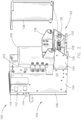
- FIG. 1 an isometric view of a diagrammatic illustration of an exemplary embodiment of a brewing apparatus 100 according to the invention is disclosed herein.
- the brewing apparatus 100 includes a chassis.
- the chassis is constructed from one or more chassis sections. It is noted herein the entire chassis or the one or more chassis sections may be fabricated from any plastic or metal known in the art.
- the one or more chassis sections may be coupled together via one or more couplers.
- the one or more couplers may include, but are not limited to, a fastener, an adhesive, a tongue-and-groove assembly, a tab-and-slot assembly, a friction clip assembly, a latching assembly, or the like.
- the chassis may house one or more components of a brewing system, the brewing system including one or more heating subsystems with any number of heating components known in the art (e.g., one or more heating elements, one or more heat-resistant components, or the like), one or more plumbing subsystems with any number of plumbing components known in the art (e.g., fluidic components including one or more pipes and pipe couplers, one or more tubes and tube couplers, or the like), and/or one or more electrical subsystems with any number of electrical components known in the art (e.g., one or more wire harnesses, one or more terminal blocks, one or more sensors, or the like). It is noted herein the various systems and subsystems within the brewing apparatus 100 may share any number of components.
- the chassis includes a front chassis section 102.
- the front chassis section 102 may include a front chassis assembly 104.
- the front chassis assembly 104 may include and/or be coupled to a server base 106. It is noted herein that, where the brewing apparatus 100 is installed in an aircraft galley, the server base 106 may configured such that coffee may drain into the server at an angle of descent up to three degrees.
- the server base 106 includes a cavity 108 dimensioned to receive a server.
- the server may include, but is not limited to, a carafe or other container known in the art capable of holding a heated liquid.
- the server may be insulated or non-insulated.
- the cavity 108 and/or the server base 106 may include one or more safety devices configured to determine whether the server is located within the cavity 108.
- the one or more safety devices may include, but are not limited to, one or more electrical sensors and/or the one or more mechanical assemblies known in the art.
- the one or more electrical sensors and/or the one or more mechanical assemblies may include, but are not limited to, one or more pressure sensors, one or more infrared (IR) sensors, one or more magnetic switches, or any sensor known in the art. It is noted herein that the brewing apparatus 100 may be configured to be non-operational when the server is not detected within the cavity 108.
- IR infrared
- the front chassis assembly 104 may include and/or be coupled to a placard or plate 110.
- the placard or plate 110 may include general information about the brewing apparatus 100 including, but not limited to, one or more manufacturer or consumer logos, one or more informational labels for the brewing apparatus 100 (e.g., either specific to the brewing apparatus 100 or as required by regulations for any similar apparatus), or the like.
- the front chassis assembly 104 includes and/or is coupled to a brew cup panel 112.
- the brew cup panel 112 may be held in a closed position or closed orientation via one or more mechanical detents.
- the one or more mechanical detents may include any assembly configured to prevent motion until a force is applied including, but not limited to, a catch, a dog, a spring dampener assembly (e.g., a spring-operated ball), or the like.
- the brew cup panel 112 may be held in a closed position or closed orientation by engaging the front chassis section 102 with one or more couplers.
- the one or more couplers may include, but are not limited to, a fastener, a tongue-and-groove assembly, a tab-and-slot assembly, a friction clip assembly, a latching assembly, or the like.
- the brew cup panel 112 may be held in a selected position or orientation (e.g., an "open position” or “open orientation,” a “closed position” or “closed orientation,” or the like) with the mechanical detent.
- a select amount of force may be required when adjusting the brew cup panel 112 from a "closed position” to an "open position” and/or vice versa to overcome the mechanical detent.
- the brew cup panel 112 and a container within the chamber or cavity 108 of the server base 106 may be operated by a user with one hand, as the mechanical detent may hold the brew cup panel 112 in an "open position" to allow the user to operate the container within the chamber 108 with the same hand.
- the brew cup panel 112 may include an operator 114.
- the brew cup panel 112 may be actuated (e.g., open and/or closed, or the like) via the operator 114.
- the operator 114 may include, but is not limited to, a slot, a tab, a bar, or the like.
- the operator 114 may be a slot between a first front surface of the brew cup panel 112 and a second front surface extruded a selected distance from a plane defined by the first front surface of the brew cup panel 112.
- the operator 114 may be configured to receive and/or interact with at least a portion of a user's hand.
- the operator 114 may include a trigger to release the one or more couplers holding the brew cup panel 112 closed by engaging the front chassis section 102.
- the trigger may be electrically-actuated.
- the trigger may include, but is not limited to, a capacitive touch sensor, or the like.
- the trigger may be mechanically-actuated.
- the trigger may include, but is not limited to, a push-push assembly, a latch assembly, a friction clip assembly, or the like.
- the brew cup panel 112 and the operator 114 may be fabricated as a single component during the manufacturing process of the brew cup panel 112.
- the operator 114 provides an added functionality and an increased level of visual aesthetics to the design of the brewing apparatus 100.
- the operator 114 may be a separate component (e.g., a handle) coupled to the first front surface of the brew cup panel 112.
- a handle may be subject to increased regulatory aircraft galley requirements and/or standards than if the operator 114 is an integrated fabricated component with the brew cup panel 112. Therefore, the above description should not be interpreted as a limitation on the present disclosure but merely an illustration.
- the brewing apparatus 100 may include one or more safety devices that are triggered when the brew cup panel 112 is closed, to prevent the brewing apparatus 100 from operating when the brew cup panel 112 is open.
- the one or more safety devices may include, but are not limited to, one or more electrical sensors, one or more mechanical assemblies, or the like.
- the brew cup panel 112 may need to be closed to trigger a safety switch, rendering a brewing cycle of the brewing apparatus 100 operable.
- the front chassis assembly 104 may include and/or be coupled to a user interface 116.
- the user interface 116 may include and/or be configured to interact with one or more display devices 118.
- the user interface 116 may include and/or be configured to interact with one or more user input devices 120.
- the user interface 116 may be a panel separate from the brew cup panel 112 and coupled to the front chassis assembly 104. It is noted herein, however, that the user interface 116 may be at least partially embedded within the brew cup panel 112. Therefore, the above description should not be interpreted as a limitation on the present disclosure but merely an illustration.
- the one or more display devices 118 may be a human-machine interface (HMI) configured to provide a user with one or more messages with respect to the operation of the brewing apparatus 100.
- the one or more messages may include, but are not limited to, status of the brewing cycle (e.g., type of brew, strength of brew, brew time remaining, or the like), user prompts (e.g., general operating information, warning messages, or the like), or the like.
- the brewed liquid is coffee
- a message about brew time remaining may be utilized by a user of the brewing apparatus 100 to ensure the taste of the brewed liquid is not affected by insufficient or excessive brew time.
- the one or more messages may include, but are not limited to, one or more vehicle operation and/or status updates.
- the one or more display devices 118 may include any display device known in the art.
- the one or more display devices 118 may include, but are not limited to, a liquid crystal display (LCD), a light-emitting diode (LED) display, an organic light-emitting diode (OLED) based display, or the like.
- LCD liquid crystal display
- LED light-emitting diode
- OLED organic light-emitting diode
- a variety of display devices may be suitable for implementation in the present disclosure and the particular choice of display device may depend on a variety of factors, including, but not limited to, form factor, cost, and the like.
- any display device 118 capable of integration with a user input device 120 e.g., touchscreen, bezel mounted interface, keyboard, mouse, trackpad, and the like
- a user input device 120 e.g., touchscreen, bezel mounted interface, keyboard, mouse, trackpad, and the like
- the one or more user input devices 120 may include any user input device known in the art.
- the one or more user input devices 120 may include, but are not limited to, a keyboard, a keypad, a touchscreen, a lever, a knob, a scroll wheel, a track ball, a switch, a dial, a sliding bar, a scroll bar, a slide, a touch pad, a paddle, a steering wheel, a joystick, a button, a bezel input device or the like.
- a touchscreen interface those skilled in the art should recognize that a large number of touchscreen interfaces may be suitable for implementation in the present disclosure.
- a display device 118 may be integrated with a touchscreen interface, such as, but not limited to, a capacitive touchscreen, a resistive touchscreen, a surface acoustic based touchscreen, an infrared based touchscreen, or the like.
- a touchscreen interface such as, but not limited to, a capacitive touchscreen, a resistive touchscreen, a surface acoustic based touchscreen, an infrared based touchscreen, or the like.
- any touchscreen interface capable of integration with the display portion of a display device 118 is suitable for implementation in the present disclosure.
- the one or more user input devices 120 may additionally include, but are not limited to, a bezel mounted interface.
- the user interface 116 may be configured to interact with and/or be integrated with a controller.
- the controller may be housed within the brewing apparatus 100.
- the controller may be a component external to the brewing apparatus 100.
- the controller may be a component of a controller of a vehicle (e.g., aircraft, or the like) in which the brewing apparatus 100 is installed.
- the controller may include one or more processors and memory.
- the memory may store one or more databases and/or a set of program instructions.
- the one or more processors may be configured to communicate with the one or more databases (e.g., receive and/or transmit a set of data) and/or execute the set of program instructions.
- the controller may be configured to receive and/or acquire data or information from components, systems, and/or components of systems (e.g., brewing systems, heating subsystems, plumbing subsystems, electrical subsystems, or the like) of the brewing apparatus 100 by a transmission medium that may include wireline and/or wireless portions.
- the controller may additionally be configured to transmit data or information to components, systems, and/or components of systems (e.g., the brewing systems, heating subsystems, plumbing subsystems, electrical subsystems, or the like) of the brewing apparatus 100 by a transmission medium that may include wireline and/or wireless portions.
- the transmission medium may serve as a data link between the controller and the systems of the brewing apparatus 100.
- the controller may be configured to send data to external systems (e.g., a controller of a vehicle in which the brewing apparatus 100 is installed) via a transmission medium (e.g., network connection).
- components, systems, and/or components of systems e.g., the brewing systems, heating subsystems, plumbing subsystems, electrical subsystems, or the like
- the brewing apparatus 100 may be configured to receive and/or transmit data between one another directly (e.g., without the need for an intermediary such as the controller). Therefore, the above description should not be interpreted as a limitation on the present disclosure but merely an illustration.
- the one or more processors may include any one or more processing elements known in the art.
- the one or more processors may include any microprocessor device configured to execute algorithms and/or program instructions.
- the one or more processors may consist of a vehicle on-board computer, handheld computer (e.g., tablet, smartphone, or phablet), desktop computer, mainframe computer system, workstation, image computer, parallel processor, or other computer system (e.g., networked computer) configured to cause the brewing apparatus 100 to perform one or more of the invention.
- handheld computer e.g., tablet, smartphone, or phablet
- desktop computer e.g., mainframe computer system
- workstation e.g., image computer
- parallel processor e.g., parallel processor
- processor may be broadly defined to encompass any device (e.g., a system on a chip (SOC), a field programmable gate array (FPGA), an application-specific integrated circuit (ASIC), or the like) including one or more processing elements, which execute the one or sets of program instructions from a non-transitory memory medium (e.g., the memory).
- SOC system on a chip
- FPGA field programmable gate array
- ASIC application-specific integrated circuit
- different components, systems, and/or components of systems e.g., brewing systems, heating subsystems, plumbing subsystems, electrical subsystems, or the like
- processor or logic elements suitable for carrying out at least a portion of the steps described throughout the present disclosure. Therefore, the above description should not be interpreted as a limitation on the present disclosure but merely an illustration.
- the memory may include any storage medium known in the art suitable for storing the set of program instructions executable by the associated one or more processors to carry out the various steps of the invention.
- the memory may include a non-transitory memory medium.
- the memory may include, but is not limited to, a read-only memory (ROM), a random access memory (RAM), a magnetic or optical memory device (e.g., disk), a magnetic tape, a solid-state drive and the like.
- the memory may be configured to provide display information to a display device 118 of the user interface 116 and/or the output of the various steps of the invention.
- the memory may be housed in a common controller housing with the one or more processors.
- the memory may, alternatively or in addition, be located remotely with respect to the physical location of the processors and/or the controller.
- the one or more processors and/or the controller may access a remote memory (e.g., server), accessible through a network (e.g., internet, intranet, and the like).
- a remote memory e.g., server
- a network e.g., internet, intranet, and the like.
- the one or more databases stored within the memory may include data that assists the controller in determining whether the brewing apparatus 100 meets a pre-determined baseline of safe operation.
- the data may be received from one or more sensors coupled to the components, systems, and/or components of systems (e.g., the brew cup panel 112, heating subsystems, plumbing subsystems, electrical subsystems, or the like) of the brewing apparatus 100.
- the pre-determined baseline of safe operation may be pre-loaded into the memory prior to operation and/or may be received by the controller during operation.
- the set of program instructions may include a set of program instructions configured to cause the one or more processors to receive data from the components, systems, and/or components of systems (e.g., brewing systems, heating subsystems, plumbing subsystems, electrical subsystems, or the like) of the brewing apparatus 100.
- the set of program instructions include a set of program instructions configured to cause the one or more processors to analyze the received data from components, systems, and/or components of systems (e.g., brewing systems, heating subsystems, plumbing subsystems, electrical subsystems, or the like) of the brewing apparatus 100.
- the set of program instructions may additionally include a set of program instructions configured to cause the one or more processors to determine an operation state based on the analyzed set of data from components, systems, and/or components of systems (e.g., brewing systems, heating subsystems, plumbing subsystems, electrical subsystems, or the like) of the brewing apparatus 100.
- systems e.g., brewing systems, heating subsystems, plumbing subsystems, electrical subsystems, or the like
- the set of program instructions may be configured to operate via a control algorithm, a neural network (e.g., with states represented as nodes and hidden nodes and transitioning between them until an output is reached via branch metrics), a kernel-based classification method, a Support Vector Machine (SVM) approach, canonical-correlation analysis (CCA), factor analysis, flexible discriminant analysis (FDA), principal component analysis (PCA), multidimensional scaling (MDS), principal component regression (PCR regression), projection pursuit, data mining, prediction-making, exploratory data analysis, supervised learning analysis, boolean logic (e.g., resulting in an output of a complete truth or complete false value), fuzzy logic (e.g., resulting in an output of one or more partial truth values instead of a complete truth or complete false value), or the like.
- a control algorithm e.g., a neural network (e.g., with states represented as nodes and hidden nodes and transitioning between them until an output is reached via branch metrics), a kernel-based classification method, a Support Vector Machine (
- the set of program instructions may be configured to operate via proportional control, feedback control, feedforward control, integral control, proportional-derivative (PD) control, proportional-integral (PI) control, proportional-integral-derivative (PID) control, or the like.
- proportional control feedback control, feedforward control, integral control, proportional-derivative (PD) control, proportional-integral (PI) control, proportional-integral-derivative (PID) control, or the like.
- the brewing apparatus 100 controller may be communicatively coupled with an onboard galley network controller of the aircraft.
- the brewing apparatus 100 controller may be configured to transmit and/or receive data from the onboard galley network controller of the aircraft.
- the brewing apparatus 100 controller may be configured to record event logs and may transmit the event logs to the onboard galley network controller.
- the brewing apparatus 100 controller may be configured to receive information and/or commands from the onboard galley network controller, either in response to or independent of transmitted event logs.
- FIG. 2 a partial exploded view of a diagrammatic illustration of an exemplary embodiment of the brewing apparatus 100 according to the invention is disclosed herein.
- the chassis includes a rear chassis section 122.
- the rear chassis section 122 may include a support bracket assembly 124.
- the chassis includes one or more guide rails 126.
- the one or more guide rails 126 may be coupled to the front chassis assembly 104 and/or the support bracket assembly 124.
- the one or more guide rails 126 may secure the brewing apparatus 100 to prevent displacement when a vehicle (e.g., aircraft, or the like) in which the brewing apparatus 100 is installed is in motion.
- the one or more guide rails 126 may be configured to engage one or more mated slots or tracks within a compartment (e.g., cavity or galley insert) in an aircraft galley.
- FIGS. 10A and 10B generally illustrate exemplary embodiments of the brewing apparatus 100 in an aircraft galley environment 1000 according to the invention.
- the brewing apparatus 100 may be configured and/or dimensioned to fit within a galley compartment, galley cavity, or the like in an aircraft galley.
- the brewing apparatus 100 may be partially inserted within a compartment of the aircraft galley.
- the brewing apparatus 100 may be fully inserted in the compartment of the aircraft galley such that a front surface of the brewing apparatus 100 is flush with surrounding aircraft galley compartments, aircraft galley apparatuses, and/or aircraft galley instruments.
- the brewing apparatus 100 may be configured and/or dimensioned to meet or exceed select regulations and/or design definitions.
- the design of the brewing apparatus 100 may meet or exceed ARINC 810 definitions.
- brewing apparatus 100 may fit within a size 1 galley, which is limited to a 31,7 cm (12.5-inch) height x 17 cm (7-inch) width x 30,5 cm (12-inch) depth footprint. It is noted herein, however, that the brewing apparatus 100 may not be required to meet any regulations or design definitions. Therefore, the above description should not be interpreted as a limitation on the present disclosure but merely an illustration.
- the rear chassis section 122 may include a connector plate 128.
- a drain tube assembly may be routed through the connector plate 128.
- the connector plate 128 may include one or more fluidic couplers 130.
- the one or more fluidic couplers 130 may be configured to receive water from storage on the vehicle.
- the one or more fluidic couplers 130 may be configured to remove waste via one or more draining processes from the brewing apparatus 100.
- the connector plate 128 may include a power input harness assembly 132 configured to receive power, data, and/or control commands from a vehicle.
- the power input harness assembly 132 may include one or more data couplers such that the brewing apparatus 100 meets or exceeds select regulations and/or design definitions.
- the one or more data couplers may be selected to meet or exceed ARINC 812 definitions.
- the brewing apparatus 100 may not be required to meet any regulations or design definitions. Therefore, the above description should not be interpreted as a limitation on the present disclosure but merely an illustration.
- the support bracket assembly 124 may include a hinge plate 136.
- the hinge plate 136 may be coupled to an access cover 138.
- the access cover 138 may be opened to allow access to internal components of the brewing apparatus 100 while remaining attached to the support bracket assembly 124.
- the access cover 138 may provide access to the controller.
- the controller may be coupled to the access cover 138, such that opening the access cover 138 provides access to the controller.
- the hinge plate 136 may include one or more grooves, through which one or more electrical connections pass through to and/or from the controller coupled to the access cover 138.
- one or more components, systems, and/or components of systems e.g., brewing systems, heating subsystems, plumbing subsystems, electrical subsystems, or the like
- systems e.g., brewing systems, heating subsystems, plumbing subsystems, electrical subsystems, or the like
- the chassis may include one or more tanks 200.
- the one or more tanks 200 may be coupled to one or more solenoid valves 202.
- the one or more solenoid valves 202 may open or close to allow water to pass through from the one or more tanks 200 to a specific plumbing subsystem of the brewing apparatus 100.
- the brewing apparatus 100 may include a solenoid valve 202 for each plumbing subsystem of the brewing apparatus 100.
- the brewing apparatus 100 may heat the water either within the one or more tanks 200 and/or during transport through a heated plumbing subsystem of the brewing apparatus 100 to selected temperatures for selected intervals to effect selected levels of coffee extraction from coffee grounds within a coffee filter pack.
- the water within the brewing apparatus 100 may be heated to temperatures meeting or exceeding 88°C (191 degrees Fahrenheit).
- the chassis may include a cover assembly 140.
- the cover assembly 140 may include a carrier handle 142.
- the carrier handle 142 may allow for easy transportation of the brewing apparatus 100, including in and/or out of a vehicle (e.g., aircraft, or the like), by a user.
- the cover assembly 140 may include one or more access ports 144.
- the cover assembly 140 is shown as a single piece/panel in FIG. 1 , it is noted herein the cover assembly 140 may be constructed from two or more pieces/panels. Therefore, the above description should not be interpreted as a limitation on the present disclosure but merely an illustration.
- the access cover 138 may be coupled to the cover assembly 140 via one or more couplers.
- the one or more couplers may include, but are not limited to, a fastener, a tongue-and-groove assembly, a tab-and-slot assembly, a friction clip assembly, a latching assembly, or the like.
- the access cover 138 may be coupled to the cover assembly 140 via one or more couplers in addition to, or in place of, a hinge assembly coupled to the hinge plate 136. In this regard, where the brewing apparatus 100 does not include the hinge assembly, the access cover 138 may be fully removable from the brewing apparatus 100.
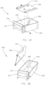
- FIGS. 3A-3D generally illustrate exemplary embodiments of a diagrammatic illustration of a brew cup 300 for the brewing apparatus 100 according to the invention.
- the brew cup 300 may include one or more walls 302 and a bottom 304.
- the one or more walls 302 and the bottom 304 may be fabricated as a single component during the manufacturing process of the brew cup 300. It is noted herein, however, that the bottom 304 may be a separate component coupled to the one or more walls 302 (e.g., via an adhesive, a fastener, or the like).
- the brew cup 300 may include a brew cup tray 306.
- the brew cup tray 306 may receive a filter pack (e.g., coffee pillow pack, or the like).
- the brew cup tray 306 may restrict the flow of heated water through the brew cup 300, holding the brewing liquid against the filter pack during a brew cycle.
- the brew cup tray 306 may be coupled to the one or more walls 302 via one or more fasteners.
- the one or more fasteners may operate as a hinge assembly to assist a user in removing the filter pack from the brew cup 300.
- the bottom 304 of the brew cup 300 may include one or more protrusions 308 extending into the volume encapsulated by the one or more walls 302.
- the brew cup tray 306 may include one or more dimples 310 corresponding to the one or more protrusions 308.
- the brew cup tray 306 may be removable and orientable within the brew cup 300. In this regard, the brew cup 300 may be configured to accept different sizes of filter packs.
- orienting the brew cup tray 306 within the brew cup 300 in a selected manner may increase or decrease the available volume within one or more walls 302 of the brew cup 300.
- the brew cup tray 306 may be oriented in the brew cup 300 with the one or more dimples 310 facing upward, such that the brew cup 300 is configured to accept up to a 3.5-oz filter pack.
- the brew cup tray 306 may be oriented in the brew cup 300 with the one or more dimples 310 facing downward, such that the volume of the brew cup 300 is reduced and the brew cup 300 is configured to accept only up to a 74 ml (2.5-oz) filter pack.
- the brew cup 300 may be configured to brew different flavors of coffee that may need different brew times and/or more coffee grounds.
- the brew cup 300 may include a cup panel 312.
- the one or more walls 302, the bottom 304, and the cup panel 312 may be fabricated as a single component during the manufacturing process of the brew cup 300. It is noted herein, however, that the cup panel 312 may be a separate component coupled to a wall of the one or more walls 302 (e.g., via an adhesive, a fastener, or the like).
- the cup panel 312 may include an operator 314.
- the operator 314 may include, but is not limited to, a slot, a tab, a bar, or the like.
- the operator 314 may be a slot between a first front surface of the cup panel 312 and a second front surface extruded a selected distance from a plane defined by the first front surface of the cup panel 312.
- the operator 314 may be configured to receive and/or interact with at least a portion of a user's hand.
- the cup panel 312 and the operator 314 may be fabricated as a single component during the manufacturing process of the brew cup 300.
- the operator 314 provides an added functionality and an increased level of visual aesthetics to the design of the brew cup 300. It is noted herein, however, that the operator 314 may be a separate component (e.g., a handle) coupled to the cup panel 312.
- the bottom 304 may include one or more drainage holes 316.
- the one or more drainage holes 316 may be holes fabricated within the bottom 304.
- the one or more drainage holes 316 may be within a mesh screen forming at least a portion of the bottom 304.
- FIG. 4 a partial exploded view of a diagrammatic illustration of an exemplary embodiment of the brewing apparatus 100 according to the invention is disclosed herein.
- the brewing apparatus 100 includes a brew cup cavity 400 dimensioned to receive the brew cup 300.
- the brew cup 300 may include one or more safety devices utilized by the brewing apparatus 100 to determine whether the brew cup 300 is located within the brew cup cavity 400.
- the one or more safety devices may include, but are not limited to, one or more electrical sensors and/or one or more mechanical assemblies known in the art.
- the one or more electrical sensors and/or one or more mechanical assemblies may include, but are not limited to, one or more pressure sensors, one or more infrared (IR) sensors, one or more magnetic switches, or any sensor known in the art.
- the bottom 304 of the brew cup 300 may include one or more magnets that interact with one or more components of the brewing apparatus 100. It is noted herein that the brewing apparatus 100 may be configured to be non-operational when the brew cup 300 is not detected within the brew cup cavity 400.
- the brewing apparatus 100 may include at least one chassis bezel 402.
- a chassis bezel 402 may be coupled to the front chassis assembly 104 and positioned between the brew cup panel 112 and the front chassis assembly 104.
- the chassis bezel 402 may surround the brew cup cavity 400, separating the brew cup cavity 400 from the brew cup panel 112.
- the brew cup panel 112 may be set at a selected angle from a substantially vertical position relative to a plane generated by a front surface of the front chassis section 102 and/or the chassis bezel 402. It is noted herein the brew cup 300 may be inserted into the brew cup cavity 400 when the brew cup panel 112 is in the "open position” or the "open orientation.”
- the brew cup panel 112 may be oriented in a substantially vertical position and/or may be oriented in a substantially parallel position relative to a plane generated by a front surface of the front chassis section 102 and/or the chassis bezel 402.
- a surface of the brew cup panel 112 may make contact with and/or be substantially flush with the front surface of the front chassis section 102 and/or the chassis bezel 402.
- the brew cup cavity 400 may be covered and/or not accessible when the brew cup panel 112 is in the "closed position" or the “closed orientation,” such that the brew cup 300 is not insertable into the brew cup cavity 400.
- the brew cup panel 112 prevents heated water and/or steam from exiting the brew cup cavity 400.
- the brew cup 300 may be removable and cleanable separate from the brewing apparatus 100.
- the brewing apparatus 100 may be left in place and wiped down, but the used brew cup 300 may be pulled, sent through catering, and replaced with a clean brew cup 300, in a similar manner to the server.
- the user interface 116 may be coupled to the chassis bezel 402, as illustrated in FIG. 6 . It is noted herein, however, that the brew cup panel 112 and/or the user interface 116 may be directly coupled with the front chassis assembly 104, bypassing the chassis bezel 402. Therefore, the above description should not be interpreted as a limitation on the present disclosure but merely an illustration.
- FIG. 5 an exemplary embodiment of a diagrammatic illustration of a brew cup panel assembly of the brewing apparatus according to the invention is disclosed herein.
- the brew cup panel assembly includes a hinge assembly 500.
- the hinge assembly 500 may include a cross member 502.
- the hinge assembly 500 may include one or more linkage assemblies 504.
- the one or more linkage assemblies 504 may be coupled to one or more mount brackets 506.
- the one or more mount brackets 506 may be coupled to a portion of the chassis (e.g., the front chassis assembly 104).
- the hinge assembly 500 may include one or more rollers 508.
- the one or more rollers 508 may be configured to interact with one or more components of the brewing apparatus 100.
- the brew cup panel assembly may include a panel mounting plate 520.
- the panel mounting plate 520 may be coupled to a surface (e.g., rear surface) of the brew cup panel 112.
- the brew cup panel 112 may be coupled to the one or more linkage assemblies 504 via the panel mounting plate 520.
- the brew cup panel 112 is easily detachable and/or replaceable, being coupled to the brewing apparatus 100 only via the panel mounting plate 520.
- the brew cup panel 112 may include one or more markings (e.g., manufacturer or consumer logos, information either specific to the brewing apparatus 100 or generally required by regulation, or the like) on the first front surface.
- the brew cup panel 112 may be swapped out for a different brew cup panel 112, instead of having to alter the brew cup panel 112 to remove the markings from the first front surface.
- the panel mounting plate 520 may include one or more controller components (e.g., processors, memory, or the like).
- the one or more controller components may be coupled to a main controller of the brewing apparatus 100 via one or more data couplers, such that the brew cup panel 112 remains easily detachable and/or replaceable
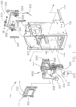
- FIGS. 6 and 7 generally illustrate exploded views of a diagrammatic illustration of an exemplary embodiment of the brewing apparatus 100 according to the invention.
- the hinge assembly 500 may be configured to couple to the front chassis assembly 104 via one or more bushings 510 coupled to the cross member 502.
- the hinge assembly 500 may be configured to rotate about an axis through the one or more bushings 510 when a force is applied to the hinge assembly 500 (e.g., a force applied via the operator 114 of the brew cup panel 112).
- the front chassis assembly 104 may include one or more tracks 602.
- the one or more tracks 602 may include, but are not limited to, one or more rails or grooves.
- the front chassis assembly 104 may include a brew head assembly 600.
- the brew head assembly 600 may include one or more tracks 604.
- the one or more tracks 604 may include, but are not limited to, one or more rails or grooves.
- the one or more rollers 508 of the hinge assembly 500 may be inserted in and engage the one or more tracks 604.
- the brew head assembly 600 may include one or more tracks 606.
- the one or more tracks 606 may include, but are not limited to, one or more rails or grooves.
- the one or more tracks 606 may be configured to receive the one or more tracks 602 coupled to the front chassis assembly 104.
- the brew cup panel 112 may be configured to actuate the brew head assembly 600 in a selected direction.
- a user may provide a force to open the brew cup panel 112 via the operator 114.
- the force may be applied to the hinge assembly 500, and the one or more rollers 508 may be inserted in and translate along the one or more tracks 604 in a first direction, engaging a first wall of the one or more tracks 604 and causing the brew head assembly 600 to raise, while the cross member 502 rotates about an axis through the one or more bushings 510.
- the one or more tracks 602 may assist in raising, lowering, and/or guiding the brew head assembly 600, as the one or more tracks 602 are inset within the one or more tracks 606 of the brew head assembly 600.
- a user may provide a force to close the brew cup panel 112 via the operator 114.
- the force may be applied to the hinge assembly 500, and the one or more rollers 508 may translate along the one or more tracks 604 in a second direction, engaging a second wall of the one or more tracks 604 and causing the brew head assembly 600 to lower, while the cross member 502 rotates about the axis through the one or more bushings 510.
- the one or more tracks 602 may assist in raising, lowering, and/or guiding the brew head assembly 600, as the one or more tracks 602 are inset within the one or more tracks 606 of the brew head assembly 600.
- the brew cup panel 112 may be coupled to the brew head assembly 600 such that opening the brew cup panel 112 via the operator 114 raises the brew head assembly 600 and closing the brew cup panel 112 via the operator 114 lowers the brew head assembly 600.
- the brew head assembly 600 may include one or more server restraints configured to secure the server within the cavity 108 of the server base 106.
- the one or more server restraints may include one or more arms 608.
- the one or more arms 608 may include one or more slots configured to receive one or more pins 610, where the one or more pins 610 are fixed to at least one of the front chassis assembly 104 and/or the server base 106.
- the one or more slots may contain the one or more pins 610 and slide up and/or down relative to the fixed pin when the brew head assembly 600 is raised and/or lowered.
- the one or more arms 608 may include one or more protrusions 612 (e.g., one or more pads).
- the one or more protrusions 612 may be configured to engage and/or disengage (e.g., make contact with and/or detach from) an exterior surface of a server positioned within the cavity 108 of the server base 106 when the brew cup panel 112 is in a closed position or closed orientation.
- the one or more server restraints may include a puck or stopper 614.
- the puck or stopper 614 may be configured to engage and/or disengage (e.g., make contact with and/or detach from) the server when the brew cup panel 112 is in a closed position or closed orientation.
- the puck or stopper 614 may be configured to engage and/or make contact with at least one of an interior surface of the server through an opening at the top of the server and/or a top edge or rim of the server.
- the puck or stopper 614 may include one or more sensors 700.
- the one or more sensors 700 may include, but are not limited to, one or more IR sensors, one or more light-emitting diode (LED) phototransistors, or the like.
- the one or more sensors 700 may be implemented to determine whether the server is within the cavity 108 of the server base 106. Alternatively or in addition, the one or more sensors 700 may be implements to determine whether the server still contains liquid from a previous brew cycle.
- the puck or stopper 614 may be coupled to the brew head assembly 600 via a bracket.
- a spring may be inserted where the bracket and the brew head assembly 600 are coupled together.
- the bracket including the puck or stopper 614 may not be entirely fixed relative to the position of the brew head assembly 600, but instead include an ability to translate some amount in a vertical motion relative to the position of the brew head assembly 600 as a server is positioned and/or removed from underneath the puck or stopper 614 within the cavity 108 of the server base 106.
- the brew head assembly 600 may include one or more brew cup 300 restraints. As illustrated in FIG. 7 , the one or more brew cup 300 restraints may include a brew head 616 coupled to an underside of the brew head assembly 600.
- the brew head 616 may be configured to engage and/or disengage (e.g., make contact with and/or detach from) the brew cup 300 when the brew cup panel 112 is in a closed position or closed orientation.
- the one or more brew heads 616 may be configured to engage and/or make contact with a top edge or rim of the brew cup 300.
- the brew head assembly 600 may include a manifold 618.
- the manifold 618 may be coupled to a solenoid 202.
- the manifold 618 may be coupled to the brew head 616. Water may flow through the brew head 616 to interact with a filter pack placed within the brew cup 300 while the brew cup 300 is positioned within the brew cup cavity 400.
- the front chassis assembly 104 includes a brew cup shelf 620. It is noted herein the brew cup cavity 400 may be a space including one or more dimensions defined by the brew head assembly 600 and the brew cup shelf 620.
- FIGS. 8A and 8B generally illustrate the brew cup shelf 620 of the brewing apparatus 100 according to the invention.
- the brew cup shelf 620 may include a frame 800.
- the frame 800 may couple to the front chassis assembly 104.
- the brew cup shelf 620 includes a recess 802 dimensioned to receive the brew cup 300.
- the recess 802 may include one or more slanted surfaces 804.
- the one or more slanted surfaces 804 may be orientated at a select angle relative to a substantially horizontal plane.
- the brew cup shelf 620 may include one or more nozzles 806 configured to receive coffee brewed by passing heated water through a filter pack including coffee grounds within the brew cup 300.
- the one or more nozzles 806 may include one or more holes 808.
- the one or more holes 808 may act as one or more flow control components to regulate the flow of a liquid into the server within the cavity 108 of the server base 106.
- the one or more holes 808 may control and/or direct the brewed coffee as it drips from the recess 802 into the server within the cavity 108 of the server base 106.
- the one or more holes 808 may control and/or direct heated water from a nozzle 810, where the nozzle 810 is coupled to a solenoid 202 different from the solenoid 202 coupled to the manifold 618.
- the server may be provided with heated water from at least two sources, to brew either coffee or another heated liquid (e.g., tea, or the like) without cross-contamination.
- the recess 802 is surrounded by one or more ledges 812.
- the one or more ledges 812 may be configured to hold the brew cup 300 when the brew cup 300 is set within the recess 802.
- the one or more ledges 812 act as a restraint to prevent the brew cup 300 from dismounting during operation of the brewing apparatus 100.
- a spring 622 is coupled to the at least one of the front chassis assembly 104, the hinge assembly 500, and/or the brew head assembly 600.
- the spring 622 may provide a returning force against the brew head assembly 600.
- the force provided by the spring 622 may maintain the brew cup panel 112 in at least one of an open position and/or a closed position when no external force is applied to the brew cup panel 112 (e.g., force applied by a user on the operator 114 of the brew cup panel 112).
- FIG. 9 a partial exploded view of a diagrammatic illustration of an exemplary embodiment of the brewing apparatus 100 according to the inventive concept is disclosed herein
- the front chassis section 102 may include a platen heater 900 within the cavity 108 of the server base 106.
- the platen heater 900 may be configured to at least heat the server within the cavity 108 of the server base 106 such that liquid within the container may be maintained at a selected temperature.
- the brewing apparatus 100 may not include a platen heater 900.
- the brewing apparatus 100 may not include a platen heater 900 when the server is insulated. Therefore, the above description should not be interpreted as a limitation on the present disclosure but merely an illustration.
- the front chassis section 102 may include one or more faucets 902.
- the one or more faucets 902 may be pivotable and/or extendable, such that the one or more faucets 902 collapse or fold against the front chassis assembly 104 (e.g., against the server base 108, the chassis bezel 402, or the like).
- the one or more faucets 902 may be fixed in place.
- the one or more faucets 902 may be coupled to a solenoid 202 different from the solenoids 202 coupled to the manifold 618 and/or the nozzle 810.
- the brewing apparatus 100 may include a third distributor of heated water, to brew either coffee or another heated liquid (e.g., tea, or the like).
- An exemplary embodiment of a method not according to the invention and present for illustration purposes only, may include one or more of the following steps. It is noted herein the method is not limited to the steps provided. For example, the method may instead include more or fewer steps. By way of another example, the method may perform the steps in an order other than provided. Therefore, the above description should not be interpreted as a limitation on the scope of the present disclosure, but merely an illustration.
- a step may include opening the brew cup panel 112.
- opening the brew cup panel 112 may disengage the one or more server restraint components (e.g., the puck or stopper 614 or the one or more protrusions 612 of the one or more arms 608) from the server within the cavity 108 of the server base 106.
- opening the brew cup panel 112 may disengage the one or more brew cup 300 restraint components (e.g., the brew head 616) from the brew cup 300 within the brew cup cavity 400.
- a step may include removing the brew cup 300 from the brew cup cavity 400 behind the brew cup panel 112. For example, the brew cup 300 may be removed from the recess 802 and subsequently lose contact with or disengage from the one or more ledges 812.
- a step may include placing a filter pack within the brew cup 300.
- a step may include inserting the brew cup 300 in the brew cup cavity 400. For example, the brew cup 300 may be inserted into the recess 802 and subsequently make contact with or engage the one or more ledges 812.
- a step may include closing the brew cup panel 112.
- closing the brew cup panel 112 may engage the one or more server restraint components (e.g., the puck or stopper 614 or the one or more protrusions 612 of the one or more arms 608) to the server within the cavity 108 of the server base 106.
- closing the brew cup panel 112 may engage the one or more brew cup 300 restraint components (e.g., the brew head 616) against the brew cup 300 within the brew cup cavity 400.
- An exemplary embodiment of a method not according to the invention and present for illustration purposes only, may include one or more of the following steps. It is noted herein the method is not limited to the steps provided. For example, the method may instead include more or fewer steps. By way of another example, the method may perform the steps in an order other than provided. Therefore, the above description should not be interpreted as a limitation on the scope of the present disclosure, but merely an illustration.
- a step may include receiving a brew command.
- a step may include performing one or more safety checks to determine whether the brew cup and/or the server is correctly positioned. For example, closing the brew cup panel 112 may transmit a ready signal and/or engage one or more safety devices to indicate the brewing system of the brewing apparatus 100 is operable. For instance, closing the brew cup panel 112 may trigger one or more safety systems that transmit a ready signal the controller that the brewing system of the brewing apparatus 100 is operable. By way of another example, inserting the brew cup 300 into the recess 802 of the brew cup shelf 800 may engage one or more safety devices (e.g., magnetic switch, or the like) to indicate the brewing system of the brewing apparatus 100 is operable.
- one or more safety devices e.g., magnetic switch, or the like
- a step may include checking water levels.
- the water levels within the tank 200 may be checked.
- the water levels in the server within the cavity 108 of the server base 106 may be checked.
- a step may include checking temperature levels of the water within the brewing apparatus 100.
- a step may include opening a selected solenoid 202 based on the brew command received from the user following completion of the one or more safety checks.
- a step may include one or more engaging one or more brewing system safety operations.
- the one or more brewing system safety operations may include monitoring of the fluid within the server via the one or more IR sensors 700.
- the one or more brewing system safety operations may include self-termination after a predefined time period.
- the predefined time period may include, but is not limited to, fifteen minutes.
- embodiments of the invention are directed to a brewing apparatus, where the brewing apparatus includes the capability to hold a filter pack within a brew cup behind a brew cup panel and the capability to engage a container housed within a container chamber during operation of the brewing apparatus, where the apparatus is configured to couple to and operate in an aircraft galley.
- embodiments of the methods may include one or more of the steps described herein. Further, such steps may be carried out in any desired order and two or more of the steps may be carried out simultaneously with one another. Two or more of the steps disclosed herein may be combined in a single step, and in some embodiments, one or more of the steps may be carried out as two or more sub-steps. Further, other steps or sub-steps may be carried in addition to, or as substitutes to one or more of the steps disclosed herein.
Landscapes
- Engineering & Computer Science (AREA)
- Food Science & Technology (AREA)
- Aviation & Aerospace Engineering (AREA)
- Mechanical Engineering (AREA)
- Physics & Mathematics (AREA)
- Thermal Sciences (AREA)
- Apparatus For Making Beverages (AREA)
Claims (15)
- Brühvorrichtung (100), umfassend:
ein Gehäuse, umfassend:einen vorderen Gehäuseabschnitt (102),einen hinteren Gehäuseabschnitt (122) undeine oder mehrere Führungsschienen (126), die dazu ausgelegt sind, den vorderen Gehäuseabschnitt (102) und den hinteren Gehäuseabschnitt (122) zu koppeln,wobei der vordere Gehäuseabschnitt (102) Folgendes umfasst:eine Serviervorrichtungsbasis (106), die einen Hohlraum (108) umfasst, der dazu ausgelegt ist, eine Serviervorrichtung aufzunehmen,einen Brühhohlraum, der dazu dimensioniert ist, eine Brühlade (300) aufzunehmen, undein Brühladenbrett (620), das eine Vertiefung (802) umfasst, wobei die Vertiefung (802) dazu ausgelegt ist, eine Brühlade (300) aufzunehmen,eine Brühkopfanordnung (600), wobei die Brühkopfanordnung (600) eine oder mehrere Serviervorrichtungshalteeinrichtungen (612, 614) und/oder eine oder mehrere Brühladenhalteeinrichtungen umfasst, undeine Brühladenplattenanordnung, umfassend:eine Scharnieranordnung (500), die dazu ausgelegt ist, mit der Brühkopfanordnung einzugreifen, undeine Brühladenplatte (112), wobei die Brühladenplatte (112) dazu ausgelegt ist, den Brühhohlraum abzudecken, wobei die Brühladenplatte (112) mit der Scharnieranordnung (500) gekoppelt ist, wobei die Brühladenplatte (112) dazu ausgelegt ist, die Brühkopfanordnung durch Betätigung der Scharnieranordnung (500) in eine ausgewählte Richtung einzustellen,wobei die Brühladenplatte (112) bewegbar ist zwischen:- einer geöffneten Ausrichtung, wobei in dieser Ausrichtung die Brühlade (300) in den Brühladenhohlraum (400) einsetzbar ist, und- einer geschlossenen Ausrichtung, wobei in dieser Ausrichtung die Brühlade (300) nicht in den Brühladenhohlraum (400) einsetzbar ist, dadurch gekennzeichnet, dass die Brühladenplatte (112) in der geschlossenen Ausrichtung verhindert, dass heißes Wasser und/oder heißer Dampf aus dem Brühladenhohlraum (400) austritt. - Vorrichtung nach Anspruch 1, wobei das Gehäuse so dimensioniert ist, dass es in ein Fach einer Apparatur, vorzugsweise einer Flugzeugbordküche, passt, und wobei die eine oder die mehreren Führungsschienen (126) dazu ausgelegt sind, mit einer oder mehreren Schienen in dem Apparaturfach einzugreifen.
- Vorrichtung nach Anspruch 1 oder 2, wobei der vordere Gehäuseabschnitt (102) die Brühladenplattenanordnung umfasst, die eine Brühladenplatte (112) umfasst, die dazu ausgelegt ist, den Brühhohlraum abzudecken, wobei die Brühladenplatte (112) vorzugsweise eine Betätigungsvorrichtung (114) umfasst, wobei die Betätigungsvorrichtung (114) einen Spalt zwischen einer ersten Vorderfläche der Brühladenplatte (112) und einer zweiten Vorderfläche umfasst, die um einen ausgewählten Abstand zu einer Ebene extrudiert ist, die durch die erste Vorderfläche der Brühladenplatte (112) definiert ist.
- Vorrichtung nach einem oder mehreren der Ansprüche 1 bis 3, wobei die Scharnieranordnung (500) Folgendes umfasst:eine oder mehrere Querstreben (502), die eine oder mehrere Buchsen (510) umfassen,eine oder mehrere Gestängeanordnungen (504),eine oder mehrere Klammern (506) undeine oder mehrere Rollen (508),wobei die Scharnieranordnung (500) über die eine oder die mehreren Klammern (506) und/oder die eine oder die mehreren Buchsen (510) mit dem vorderen Gehäuseabschnitt (102) gekoppelt ist,wobei die eine oder die mehreren Rollen (508) dazu ausgelegt sind, mit einer oder mehreren Schienen (604) auf einer Außenfläche der Brühkopfanordnung (600) einzugreifen.
- Vorrichtung nach einem oder mehreren der Ansprüche 1 bis 4, umfassend:
wenigstens eine Arretierung, die mit der Brühkopfanordnung (600) gekoppelt ist, wobei die wenigstens eine Arretierung dazu ausgelegt ist, die Brühladenplatte (112) in einer ausgewählten Ausrichtung zu halten. - Vorrichtung nach Anspruch 5, wobei die ausgewählte Ausrichtung der Brühladenplatte (112) eine Ausrichtung, die parallel zu einer Ebene verläuft, die durch eine Vorderfläche des vorderen Gehäuseabschnitts (102) erzeugt wird, oder eine Ausrichtung, die in einem Winkel relativ zu einer Ebene verläuft, die durch eine Vorderfläche des vorderen Gehäuseabschnitts (102) erzeugt wird, umfasst.
- Vorrichtung nach einem oder mehreren der Ansprüche 1 bis 6, wobei der vordere Gehäuseabschnitt (102) eine Gehäuseblende (402) umfasst.
- Vorrichtung nach einem oder mehreren der Ansprüche 1 bis 7, umfassend:
eine Bedienoberfläche (116), die eine oder mehrere Anzeigevorrichtungen (118) und/oder eine oder mehrere Benutzereingabevorrichtungen (120) umfasst, wobei die Bedienoberfläche (116) vorzugsweise mit der Gehäuseblende (402) und/oder der Brühladenplatte (112) gekoppelt ist. - Vorrichtung nach einem oder mehreren der Ansprüche 1 bis 8, wobei die eine oder die mehreren Serviervorrichtungshalteeinrichtungen einen oder mehrere Vorsprünge (612) an einem oder mehreren Armen (608) umfassen, wobei der eine oder die mehreren Vorsprünge (612) dazu ausgelegt sind, in Eingriff und/oder außer Eingriff mit einer Außenfläche der Serviervorrichtung zu gelangen, wenn die Brühkopfanordnung (600) durch Betätigung der Scharnieranordnung (500) in eine ausgewählte Richtung eingestellt wird.
- Vorrichtung nach einem oder mehreren der Ansprüche 1 bis 9, wobei die eine oder die mehreren Serviervorrichtungshalteeinrichtungen einen oder mehrere Anschläge (614) umfassen, wobei der eine oder die mehreren Anschläge (614) dazu ausgelegt sind, in Eingriff und/oder außer Eingriff mit einer Innenfläche der Serviervorrichtung zu gelangen, wenn die Brühkopfanordnung (600) durch Betätigung der Scharnieranordnung (500) in eine ausgewählte Richtung eingestellt wird, wobei der eine oder die mehreren Anschläge (614) vorzugsweise einen oder mehrere Sensoren (700) umfassen, die dazu ausgelegt sind, die Position der Serviervorrichtung in dem Hohlraum (108) der Serviervorrichtungsbasis (106) und/oder eine Menge von Flüssigkeit in der Serviervorrichtung zu bestimmen.
- Vorrichtung nach einem oder mehreren der Ansprüche 1 bis 10, wobei die Brühlade (300) Folgendes umfasst:eine oder mehrere Wände (302) und einen Boden (304), wobei der Boden (302) ein oder mehrere Löcher (316) umfasst, wobei der Boden (302) einen oder mehrere Vorsprünge (308) umfasst, undeine Brühladenablage (306), die eine oder mehrere Vertiefungen (310) umfasst, die dem einen oder den mehreren Vorsprüngen (308) des Bodens (304) entsprechen, wobei die Brühladenablage (306) mit der einen oder den mehreren Wänden (302) gekoppelt ist, wobei die Brühladenablage (306) innerhalb der einen oder der mehreren Wände (302) zwischen einer ersten Position und einer zweiten Position drehbar ist, wobei die Brühladenablage (306) innerhalb der einen oder der mehreren Wände (302) zwischen einer ersten Position und einer zweiten Position ausrichtbar ist.
- Vorrichtung nach Anspruch 11, wobei die Brühladenablage (306) dazu ausgelegt ist, eine Kaffeefilterpackung vorzugsweise innerhalb der Brühlade hinter einer Brühladenplatte zu halten, wobei die Brühladenablage (306) dazu ausgelegt ist, während eines Brühzyklus für einen ausgewählten Zeitraum eine Flüssigkeit gegen eine Kaffeefilterpackung zurückzuhalten, bevor die Flüssigkeit durch das eine oder die mehreren Löcher (316) in dem Boden (304) der Brühladenablage (306) austritt, und/oder wobei die eine oder die mehreren Brühladenhalteeinrichtungen einen Brühkopf (616) umfassen, wobei der Brühkopf (616) dazu ausgelegt ist, in Eingriff und/oder außer Eingriff mit einer Oberkante der einen oder der mehreren Wände der Brühlade (300) zu gelangen, wenn die Brühkopfanordnung (600) durch Betätigung der Scharnieranordnung (500) in eine ausgewählte Richtung eingestellt wird.
- Vorrichtung nach einem oder mehreren der Ansprüche 1 bis 12, wobei das Gehäuse Folgendes umfasst:einen oder mehrere Tanks (200) und ein oder mehrere Solenoide (202) undeine Abdeckanordnung (140), die dazu ausgelegt ist, den einen oder die mehreren Tanks (200) und/oder das eine oder die mehreren Solenoide (202) zu umschließen.
- Vorrichtung nach Anspruch 13, wobei das eine oder die mehreren Solenoide (202) Folgendes umfassen:ein Brühkopfsolenoid, das dazu ausgelegt ist, der Brühkopfanordnung (600) eine Flüssigkeit zuzuführen,ein Brühladenbrettsolenoid, das dazu ausgelegt ist, dem Brühladenbrett (620) eine Flüssigkeit zuzuführen, undein Auslaufventilsolenoid, das dazu ausgelegt ist, einem Auslaufventil (902) eine Flüssigkeit zuzuführen,und/oder wobei der hintere Gehäuseabschnitt (122) Folgendes umfasst:eine Verbindungsplatte (128), wobei die Verbindungsplatte (128) einen oder mehrere Datenkoppler und/oder einen oder mehrere Flüssigkeitskoppler (130) umfasst, wobei der eine oder die mehreren Datenkoppler und/oder der eine oder die mehreren Flüssigkeitskoppler (130) dazu ausgelegt sind, einer oder mehreren Flugzeugvorschriften zu entsprechen, undeine Zugangsabdeckung (138), die dazu ausgelegt ist, den Zugang zu einer oder mehreren Komponenten bereitzustellen, die von der Abdeckanordnung (140) umschlossen sind.
- Apparatur, vorzugsweise eine Flugzeugbordküche, wobei die Apparatur ein Fach umfasst, in das eine Brühvorrichtung (100) nach einem oder mehreren der Ansprüche 1 bis 14 eingepasst ist.
Applications Claiming Priority (1)
| Application Number | Priority Date | Filing Date | Title |
|---|---|---|---|
| US15/970,633 US10932609B2 (en) | 2018-05-03 | 2018-05-03 | Aircraft galley brewing apparatus |
Publications (2)
| Publication Number | Publication Date |
|---|---|
| EP3571964A1 EP3571964A1 (de) | 2019-11-27 |
| EP3571964B1 true EP3571964B1 (de) | 2023-07-26 |
Family
ID=66379738
Family Applications (1)
| Application Number | Title | Priority Date | Filing Date |
|---|---|---|---|
| EP19172190.1A Active EP3571964B1 (de) | 2018-05-03 | 2019-05-02 | Brühvorrichtung für flugzeugbordküche |
Country Status (3)
| Country | Link |
|---|---|
| US (1) | US10932609B2 (de) |
| EP (1) | EP3571964B1 (de) |
| CN (1) | CN110432770B (de) |
Families Citing this family (9)
| Publication number | Priority date | Publication date | Assignee | Title |
|---|---|---|---|---|
| US10932609B2 (en) * | 2018-05-03 | 2021-03-02 | Rockwell Collins, Inc. | Aircraft galley brewing apparatus |
| US11401703B1 (en) * | 2019-11-04 | 2022-08-02 | B/E Aerospace, Inc. | Hand washing station for galley monument |
| GB202006177D0 (en) * | 2020-04-27 | 2020-06-10 | Ipeco Holdings Ltd | Beverage dispensing machine |
| EP4036479A1 (de) * | 2021-01-29 | 2022-08-03 | Koninklijke Fabriek Inventum B.V. | Wassereinspritzsystem für öfen und verfahren zum einspritzen |
| US11946646B2 (en) | 2021-01-29 | 2024-04-02 | B/E Aerospace, Inc. | Water injection system for ovens and method of injection |
| USD1025685S1 (en) * | 2022-10-11 | 2024-05-07 | Nes(Foshan) Hardware Electrical Appliance Manufacture Co., Ltd | Coffee pot |
| IT202300000297A1 (it) * | 2023-01-12 | 2024-07-12 | Dalla Corte S R L | Apparato modulare per la preparazione di bevande a base di caffe', latte e infusi |
| EP4570657A1 (de) * | 2023-12-14 | 2025-06-18 | B/E Aerospace, Inc. | Tragbarer einsatz |
| CN118452694B (zh) * | 2024-07-12 | 2024-10-01 | 广州吉谷电器有限公司 | 一种煮茶的加热控制方法及系统 |
Family Cites Families (17)
| Publication number | Priority date | Publication date | Assignee | Title |
|---|---|---|---|---|
| US2737880A (en) * | 1956-03-13 | johnson | ||
| US3181732A (en) * | 1961-01-26 | 1965-05-04 | Gen Foods Corp | Beverage apparatus |
| US3413909A (en) * | 1967-06-15 | 1968-12-03 | William Heier | Coffeemaking apparatus |
| US4949627A (en) * | 1989-03-09 | 1990-08-21 | Nordskog Robert A | Coffee maker for use in aircraft |
| US6047630A (en) * | 1998-02-16 | 2000-04-11 | Be Aerospace, Inc. | Beverage brewing device having an integral beverage server locking apparatus |
| ITRM990017U1 (it) * | 1999-02-01 | 2000-08-01 | Goodrich Co B F | Macchina per caffe' all'americana per impieghi aeronautici. |
| US6227101B1 (en) * | 1999-12-10 | 2001-05-08 | Masoud Rabadi | Coffeemaker with automated interlocks |
| US6904840B1 (en) * | 2004-01-28 | 2005-06-14 | Grindmaster Corporation | Brewer apparatus with improved tray assembly |
| US7017408B2 (en) * | 2004-02-13 | 2006-03-28 | Be Intellectual Property, Inc. | Electro-optic liquid level sensing system for aircraft beverage brewing |
| JP4188854B2 (ja) * | 2004-02-20 | 2008-12-03 | 株式会社ジャムコ | 折畳み式コーヒーメーカー |
| US7891287B2 (en) * | 2004-06-16 | 2011-02-22 | Mag Aerospace Industries, Inc. | Coffee maker suitable for aircraft use |
| US8061263B1 (en) * | 2007-04-16 | 2011-11-22 | Richard W. Hein | Sensor head and brew cup for a beverage brewing device |
| CA2723189A1 (en) | 2008-04-30 | 2009-11-05 | Bunn-O-Matic Corporation | Brewer including substance removal assembly |
| US9049959B2 (en) * | 2009-09-11 | 2015-06-09 | The Richards Corporation | Coffee makers |
| US8573115B2 (en) * | 2010-11-15 | 2013-11-05 | Conair Corporation | Brewed beverage appliance and method |
| ITRM20150159A1 (it) * | 2015-04-14 | 2016-10-14 | Iacobucci Hf Aerospace S P A | Macchina erogatrice di bevande |
| US10932609B2 (en) * | 2018-05-03 | 2021-03-02 | Rockwell Collins, Inc. | Aircraft galley brewing apparatus |
-
2018
- 2018-05-03 US US15/970,633 patent/US10932609B2/en active Active
-
2019
- 2019-04-28 CN CN201910348107.8A patent/CN110432770B/zh active Active
- 2019-05-02 EP EP19172190.1A patent/EP3571964B1/de active Active
Also Published As
| Publication number | Publication date |
|---|---|
| US20190335937A1 (en) | 2019-11-07 |
| EP3571964A1 (de) | 2019-11-27 |
| US10932609B2 (en) | 2021-03-02 |
| CN110432770A (zh) | 2019-11-12 |
| CN110432770B (zh) | 2023-03-28 |
Similar Documents
| Publication | Publication Date | Title |
|---|---|---|
| EP3571964B1 (de) | Brühvorrichtung für flugzeugbordküche | |
| EP3708036B1 (de) | Brauvorrichtung | |
| US12251046B2 (en) | Modular food holding system | |
| US12449133B2 (en) | Automatic oven | |
| US9962038B2 (en) | Modular food holding system | |
| US10271689B2 (en) | Modular food holding system | |
| US9357787B2 (en) | Forced moisture evacuation for rapid baking | |
| CA2867153C (en) | Vehicle oven having an optimized water vapor injector | |
| US20170071412A1 (en) | Modular Food Holding System | |
| US20170071410A1 (en) | Modular food holding system | |
| WO2017176811A1 (en) | Vertically translating stowage compartment for aircraft passenger suite | |
| US20210032089A1 (en) | Refrigerator appliance with timed preheating for dispensed fluids | |
| US9618212B2 (en) | Vehicle oven having optimized airflow | |
| CN116075255A (zh) | 用于便携式环境受控容器的方法、系统和装置 | |
| US20210353096A1 (en) | Vent valve flow fuse | |
| CN105167631A (zh) | 一种烤箱面板自动冷却降温系统、方法及烤箱 | |
| CN105121279A (zh) | 用于在飞机厨房中使用的双深单宽炉具 | |
| WO2017064821A1 (ja) | 鍵付きウォーターサーバー | |
| KR200477159Y1 (ko) | 유수분리식 튀김기 | |
| JP2017074989A (ja) | 鍵付きウォーターサーバー | |
| CN108851968B (zh) | 烹饪器具 | |
| CN112438602B (zh) | 用于飞机泡制设备的多位置往复阀组件 | |
| EP3381802A1 (de) | Spültischanordnung, bordküchenabteil und bordküche | |
| JP3111081U (ja) | 発酵器 | |
| BR202015018823Y1 (pt) | disposição construtiva aplicada em churrasqueira elétrica |
Legal Events
| Date | Code | Title | Description |
|---|---|---|---|
| PUAI | Public reference made under article 153(3) epc to a published international application that has entered the european phase |
Free format text: ORIGINAL CODE: 0009012 |
|
| STAA | Information on the status of an ep patent application or granted ep patent |
Free format text: STATUS: THE APPLICATION HAS BEEN PUBLISHED |
|
| AK | Designated contracting states |
Kind code of ref document: A1 Designated state(s): AL AT BE BG CH CY CZ DE DK EE ES FI FR GB GR HR HU IE IS IT LI LT LU LV MC MK MT NL NO PL PT RO RS SE SI SK SM TR |
|
| AX | Request for extension of the european patent |
Extension state: BA ME |
|
| STAA | Information on the status of an ep patent application or granted ep patent |
Free format text: STATUS: REQUEST FOR EXAMINATION WAS MADE |
|
| 17P | Request for examination filed |
Effective date: 20200526 |
|
| RBV | Designated contracting states (corrected) |
Designated state(s): AL AT BE BG CH CY CZ DE DK EE ES FI FR GB GR HR HU IE IS IT LI LT LU LV MC MK MT NL NO PL PT RO RS SE SI SK SM TR |
|
| STAA | Information on the status of an ep patent application or granted ep patent |
Free format text: STATUS: EXAMINATION IS IN PROGRESS |
|
| 17Q | First examination report despatched |
Effective date: 20201005 |
|
| GRAP | Despatch of communication of intention to grant a patent |
Free format text: ORIGINAL CODE: EPIDOSNIGR1 |
|
| STAA | Information on the status of an ep patent application or granted ep patent |
Free format text: STATUS: GRANT OF PATENT IS INTENDED |
|
| INTG | Intention to grant announced |
Effective date: 20230330 |
|
| GRAS | Grant fee paid |
Free format text: ORIGINAL CODE: EPIDOSNIGR3 |
|
| GRAA | (expected) grant |
Free format text: ORIGINAL CODE: 0009210 |
|
| STAA | Information on the status of an ep patent application or granted ep patent |
Free format text: STATUS: THE PATENT HAS BEEN GRANTED |
|
| P01 | Opt-out of the competence of the unified patent court (upc) registered |
Effective date: 20230606 |
|
| AK | Designated contracting states |
Kind code of ref document: B1 Designated state(s): AL AT BE BG CH CY CZ DE DK EE ES FI FR GB GR HR HU IE IS IT LI LT LU LV MC MK MT NL NO PL PT RO RS SE SI SK SM TR |
|
| REG | Reference to a national code |
Ref country code: CH Ref legal event code: EP |
|
| REG | Reference to a national code |
Ref country code: IE Ref legal event code: FG4D |
|
| REG | Reference to a national code |
Ref country code: DE Ref legal event code: R096 Ref document number: 602019033375 Country of ref document: DE |
|
| REG | Reference to a national code |
Ref country code: LT Ref legal event code: MG9D |
|
| REG | Reference to a national code |
Ref country code: NL Ref legal event code: MP Effective date: 20230726 |
|
| REG | Reference to a national code |
Ref country code: AT Ref legal event code: MK05 Ref document number: 1590909 Country of ref document: AT Kind code of ref document: T Effective date: 20230726 |
|
| PG25 | Lapsed in a contracting state [announced via postgrant information from national office to epo] |
Ref country code: NL Free format text: LAPSE BECAUSE OF FAILURE TO SUBMIT A TRANSLATION OF THE DESCRIPTION OR TO PAY THE FEE WITHIN THE PRESCRIBED TIME-LIMIT Effective date: 20230726 |
|
| PG25 | Lapsed in a contracting state [announced via postgrant information from national office to epo] |
Ref country code: GR Free format text: LAPSE BECAUSE OF FAILURE TO SUBMIT A TRANSLATION OF THE DESCRIPTION OR TO PAY THE FEE WITHIN THE PRESCRIBED TIME-LIMIT Effective date: 20231027 |
|
| PG25 | Lapsed in a contracting state [announced via postgrant information from national office to epo] |
Ref country code: IS Free format text: LAPSE BECAUSE OF FAILURE TO SUBMIT A TRANSLATION OF THE DESCRIPTION OR TO PAY THE FEE WITHIN THE PRESCRIBED TIME-LIMIT Effective date: 20231126 |
|
| PG25 | Lapsed in a contracting state [announced via postgrant information from national office to epo] |
Ref country code: LT Free format text: LAPSE BECAUSE OF FAILURE TO SUBMIT A TRANSLATION OF THE DESCRIPTION OR TO PAY THE FEE WITHIN THE PRESCRIBED TIME-LIMIT Effective date: 20230726 Ref country code: IS Free format text: LAPSE BECAUSE OF FAILURE TO SUBMIT A TRANSLATION OF THE DESCRIPTION OR TO PAY THE FEE WITHIN THE PRESCRIBED TIME-LIMIT Effective date: 20231126 Ref country code: HR Free format text: LAPSE BECAUSE OF FAILURE TO SUBMIT A TRANSLATION OF THE DESCRIPTION OR TO PAY THE FEE WITHIN THE PRESCRIBED TIME-LIMIT Effective date: 20230726 Ref country code: GR Free format text: LAPSE BECAUSE OF FAILURE TO SUBMIT A TRANSLATION OF THE DESCRIPTION OR TO PAY THE FEE WITHIN THE PRESCRIBED TIME-LIMIT Effective date: 20231027 Ref country code: FI Free format text: LAPSE BECAUSE OF FAILURE TO SUBMIT A TRANSLATION OF THE DESCRIPTION OR TO PAY THE FEE WITHIN THE PRESCRIBED TIME-LIMIT Effective date: 20230726 Ref country code: AT Free format text: LAPSE BECAUSE OF FAILURE TO SUBMIT A TRANSLATION OF THE DESCRIPTION OR TO PAY THE FEE WITHIN THE PRESCRIBED TIME-LIMIT Effective date: 20230726 Ref country code: SE Free format text: LAPSE BECAUSE OF FAILURE TO SUBMIT A TRANSLATION OF THE DESCRIPTION OR TO PAY THE FEE WITHIN THE PRESCRIBED TIME-LIMIT Effective date: 20230726 Ref country code: RS Free format text: LAPSE BECAUSE OF FAILURE TO SUBMIT A TRANSLATION OF THE DESCRIPTION OR TO PAY THE FEE WITHIN THE PRESCRIBED TIME-LIMIT Effective date: 20230726 Ref country code: PT Free format text: LAPSE BECAUSE OF FAILURE TO SUBMIT A TRANSLATION OF THE DESCRIPTION OR TO PAY THE FEE WITHIN THE PRESCRIBED TIME-LIMIT Effective date: 20231127 Ref country code: NO Free format text: LAPSE BECAUSE OF FAILURE TO SUBMIT A TRANSLATION OF THE DESCRIPTION OR TO PAY THE FEE WITHIN THE PRESCRIBED TIME-LIMIT Effective date: 20231026 Ref country code: LV Free format text: LAPSE BECAUSE OF FAILURE TO SUBMIT A TRANSLATION OF THE DESCRIPTION OR TO PAY THE FEE WITHIN THE PRESCRIBED TIME-LIMIT Effective date: 20230726 |
|
| PG25 | Lapsed in a contracting state [announced via postgrant information from national office to epo] |
Ref country code: PL Free format text: LAPSE BECAUSE OF FAILURE TO SUBMIT A TRANSLATION OF THE DESCRIPTION OR TO PAY THE FEE WITHIN THE PRESCRIBED TIME-LIMIT Effective date: 20230726 |
|
| PG25 | Lapsed in a contracting state [announced via postgrant information from national office to epo] |
Ref country code: ES Free format text: LAPSE BECAUSE OF FAILURE TO SUBMIT A TRANSLATION OF THE DESCRIPTION OR TO PAY THE FEE WITHIN THE PRESCRIBED TIME-LIMIT Effective date: 20230726 |
|
| REG | Reference to a national code |
Ref country code: DE Ref legal event code: R097 Ref document number: 602019033375 Country of ref document: DE |
|
| PG25 | Lapsed in a contracting state [announced via postgrant information from national office to epo] |
Ref country code: SM Free format text: LAPSE BECAUSE OF FAILURE TO SUBMIT A TRANSLATION OF THE DESCRIPTION OR TO PAY THE FEE WITHIN THE PRESCRIBED TIME-LIMIT Effective date: 20230726 Ref country code: RO Free format text: LAPSE BECAUSE OF FAILURE TO SUBMIT A TRANSLATION OF THE DESCRIPTION OR TO PAY THE FEE WITHIN THE PRESCRIBED TIME-LIMIT Effective date: 20230726 Ref country code: ES Free format text: LAPSE BECAUSE OF FAILURE TO SUBMIT A TRANSLATION OF THE DESCRIPTION OR TO PAY THE FEE WITHIN THE PRESCRIBED TIME-LIMIT Effective date: 20230726 Ref country code: EE Free format text: LAPSE BECAUSE OF FAILURE TO SUBMIT A TRANSLATION OF THE DESCRIPTION OR TO PAY THE FEE WITHIN THE PRESCRIBED TIME-LIMIT Effective date: 20230726 Ref country code: DK Free format text: LAPSE BECAUSE OF FAILURE TO SUBMIT A TRANSLATION OF THE DESCRIPTION OR TO PAY THE FEE WITHIN THE PRESCRIBED TIME-LIMIT Effective date: 20230726 Ref country code: CZ Free format text: LAPSE BECAUSE OF FAILURE TO SUBMIT A TRANSLATION OF THE DESCRIPTION OR TO PAY THE FEE WITHIN THE PRESCRIBED TIME-LIMIT Effective date: 20230726 Ref country code: SK Free format text: LAPSE BECAUSE OF FAILURE TO SUBMIT A TRANSLATION OF THE DESCRIPTION OR TO PAY THE FEE WITHIN THE PRESCRIBED TIME-LIMIT Effective date: 20230726 |
|
| PG25 | Lapsed in a contracting state [announced via postgrant information from national office to epo] |
Ref country code: IT Free format text: LAPSE BECAUSE OF FAILURE TO SUBMIT A TRANSLATION OF THE DESCRIPTION OR TO PAY THE FEE WITHIN THE PRESCRIBED TIME-LIMIT Effective date: 20230726 |
|
| PLBE | No opposition filed within time limit |
Free format text: ORIGINAL CODE: 0009261 |
|
| STAA | Information on the status of an ep patent application or granted ep patent |
Free format text: STATUS: NO OPPOSITION FILED WITHIN TIME LIMIT |
|
| 26N | No opposition filed |
Effective date: 20240429 |
|
| PG25 | Lapsed in a contracting state [announced via postgrant information from national office to epo] |
Ref country code: SI Free format text: LAPSE BECAUSE OF FAILURE TO SUBMIT A TRANSLATION OF THE DESCRIPTION OR TO PAY THE FEE WITHIN THE PRESCRIBED TIME-LIMIT Effective date: 20230726 |
|
| PG25 | Lapsed in a contracting state [announced via postgrant information from national office to epo] |
Ref country code: BG Free format text: LAPSE BECAUSE OF FAILURE TO SUBMIT A TRANSLATION OF THE DESCRIPTION OR TO PAY THE FEE WITHIN THE PRESCRIBED TIME-LIMIT Effective date: 20230726 |
|
| PG25 | Lapsed in a contracting state [announced via postgrant information from national office to epo] |
Ref country code: BG Free format text: LAPSE BECAUSE OF FAILURE TO SUBMIT A TRANSLATION OF THE DESCRIPTION OR TO PAY THE FEE WITHIN THE PRESCRIBED TIME-LIMIT Effective date: 20230726 |
|
| REG | Reference to a national code |
Ref country code: CH Ref legal event code: PL |
|
| PG25 | Lapsed in a contracting state [announced via postgrant information from national office to epo] |
Ref country code: MC Free format text: LAPSE BECAUSE OF FAILURE TO SUBMIT A TRANSLATION OF THE DESCRIPTION OR TO PAY THE FEE WITHIN THE PRESCRIBED TIME-LIMIT Effective date: 20230726 |
|
| PG25 | Lapsed in a contracting state [announced via postgrant information from national office to epo] |
Ref country code: LU Free format text: LAPSE BECAUSE OF NON-PAYMENT OF DUE FEES Effective date: 20240502 |
|
| PG25 | Lapsed in a contracting state [announced via postgrant information from national office to epo] |
Ref country code: MC Free format text: LAPSE BECAUSE OF FAILURE TO SUBMIT A TRANSLATION OF THE DESCRIPTION OR TO PAY THE FEE WITHIN THE PRESCRIBED TIME-LIMIT Effective date: 20230726 Ref country code: LU Free format text: LAPSE BECAUSE OF NON-PAYMENT OF DUE FEES Effective date: 20240502 Ref country code: CH Free format text: LAPSE BECAUSE OF NON-PAYMENT OF DUE FEES Effective date: 20240531 |
|
| REG | Reference to a national code |
Ref country code: BE Ref legal event code: MM Effective date: 20240531 |
|
| PG25 | Lapsed in a contracting state [announced via postgrant information from national office to epo] |
Ref country code: IE Free format text: LAPSE BECAUSE OF NON-PAYMENT OF DUE FEES Effective date: 20240502 |
|
| PG25 | Lapsed in a contracting state [announced via postgrant information from national office to epo] |
Ref country code: BE Free format text: LAPSE BECAUSE OF NON-PAYMENT OF DUE FEES Effective date: 20240531 |
|
| PGFP | Annual fee paid to national office [announced via postgrant information from national office to epo] |
Ref country code: DE Payment date: 20250423 Year of fee payment: 7 |
|
| PGFP | Annual fee paid to national office [announced via postgrant information from national office to epo] |
Ref country code: GB Payment date: 20250423 Year of fee payment: 7 |
|
| PGFP | Annual fee paid to national office [announced via postgrant information from national office to epo] |
Ref country code: FR Payment date: 20250423 Year of fee payment: 7 |
|
| PG25 | Lapsed in a contracting state [announced via postgrant information from national office to epo] |
Ref country code: CY Free format text: LAPSE BECAUSE OF FAILURE TO SUBMIT A TRANSLATION OF THE DESCRIPTION OR TO PAY THE FEE WITHIN THE PRESCRIBED TIME-LIMIT; INVALID AB INITIO Effective date: 20190502 |
|
| PG25 | Lapsed in a contracting state [announced via postgrant information from national office to epo] |
Ref country code: HU Free format text: LAPSE BECAUSE OF FAILURE TO SUBMIT A TRANSLATION OF THE DESCRIPTION OR TO PAY THE FEE WITHIN THE PRESCRIBED TIME-LIMIT; INVALID AB INITIO Effective date: 20190502 |