EP3571443B2 - Dispositif de régulation d'un taux de mélange d'un mélange gazeux - Google Patents
Dispositif de régulation d'un taux de mélange d'un mélange gazeux Download PDFInfo
- Publication number
- EP3571443B2 EP3571443B2 EP18785308.0A EP18785308A EP3571443B2 EP 3571443 B2 EP3571443 B2 EP 3571443B2 EP 18785308 A EP18785308 A EP 18785308A EP 3571443 B2 EP3571443 B2 EP 3571443B2
- Authority
- EP
- European Patent Office
- Prior art keywords
- gas
- sensor
- thermal
- air
- parameter
- Prior art date
- Legal status (The legal status is an assumption and is not a legal conclusion. Google has not performed a legal analysis and makes no representation as to the accuracy of the status listed.)
- Active
Links
- 239000000203 mixture Substances 0.000 title claims description 129
- 230000001105 regulatory effect Effects 0.000 title claims description 21
- 239000007789 gas Substances 0.000 claims description 298
- 238000000034 method Methods 0.000 claims description 47
- 239000002737 fuel gas Substances 0.000 claims description 42
- QVGXLLKOCUKJST-UHFFFAOYSA-N atomic oxygen Chemical compound [O] QVGXLLKOCUKJST-UHFFFAOYSA-N 0.000 claims description 21
- 239000001301 oxygen Substances 0.000 claims description 21
- 229910052760 oxygen Inorganic materials 0.000 claims description 21
- 230000007257 malfunction Effects 0.000 claims description 14
- 230000003444 anaesthetic effect Effects 0.000 claims description 7
- MYMOFIZGZYHOMD-UHFFFAOYSA-N Dioxygen Chemical compound O=O MYMOFIZGZYHOMD-UHFFFAOYSA-N 0.000 claims description 3
- 229910001882 dioxygen Inorganic materials 0.000 claims description 3
- 239000011261 inert gas Substances 0.000 claims description 3
- 239000000446 fuel Substances 0.000 description 79
- 238000011144 upstream manufacturing Methods 0.000 description 22
- 238000010438 heat treatment Methods 0.000 description 21
- 238000002485 combustion reaction Methods 0.000 description 15
- 239000012159 carrier gas Substances 0.000 description 13
- 238000005259 measurement Methods 0.000 description 11
- VNWKTOKETHGBQD-UHFFFAOYSA-N methane Chemical compound C VNWKTOKETHGBQD-UHFFFAOYSA-N 0.000 description 10
- 239000000758 substrate Substances 0.000 description 8
- 239000012530 fluid Substances 0.000 description 6
- 230000008859 change Effects 0.000 description 5
- 230000001276 controlling effect Effects 0.000 description 4
- 239000000463 material Substances 0.000 description 4
- 239000003345 natural gas Substances 0.000 description 4
- 230000008569 process Effects 0.000 description 4
- 241001465754 Metazoa Species 0.000 description 3
- 238000002347 injection Methods 0.000 description 3
- 239000007924 injection Substances 0.000 description 3
- 238000012986 modification Methods 0.000 description 3
- 230000004048 modification Effects 0.000 description 3
- VYPSYNLAJGMNEJ-UHFFFAOYSA-N Silicium dioxide Chemical compound O=[Si]=O VYPSYNLAJGMNEJ-UHFFFAOYSA-N 0.000 description 2
- 238000012937 correction Methods 0.000 description 2
- 238000010586 diagram Methods 0.000 description 2
- 239000012528 membrane Substances 0.000 description 2
- 239000002184 metal Substances 0.000 description 2
- 229910021420 polycrystalline silicon Inorganic materials 0.000 description 2
- 229910052814 silicon oxide Inorganic materials 0.000 description 2
- 230000001052 transient effect Effects 0.000 description 2
- 206010002091 Anaesthesia Diseases 0.000 description 1
- 101100021996 Arabidopsis thaliana CYP97C1 gene Proteins 0.000 description 1
- 101100510695 Arabidopsis thaliana LUT2 gene Proteins 0.000 description 1
- UGFAIRIUMAVXCW-UHFFFAOYSA-N Carbon monoxide Chemical compound [O+]#[C-] UGFAIRIUMAVXCW-UHFFFAOYSA-N 0.000 description 1
- PIWKPBJCKXDKJR-UHFFFAOYSA-N Isoflurane Chemical compound FC(F)OC(Cl)C(F)(F)F PIWKPBJCKXDKJR-UHFFFAOYSA-N 0.000 description 1
- 229910052581 Si3N4 Inorganic materials 0.000 description 1
- XUIMIQQOPSSXEZ-UHFFFAOYSA-N Silicon Chemical compound [Si] XUIMIQQOPSSXEZ-UHFFFAOYSA-N 0.000 description 1
- 230000003044 adaptive effect Effects 0.000 description 1
- 230000037005 anaesthesia Effects 0.000 description 1
- 230000008901 benefit Effects 0.000 description 1
- 238000009530 blood pressure measurement Methods 0.000 description 1
- 238000005314 correlation function Methods 0.000 description 1
- 230000001419 dependent effect Effects 0.000 description 1
- 238000001514 detection method Methods 0.000 description 1
- 230000000694 effects Effects 0.000 description 1
- 239000003546 flue gas Substances 0.000 description 1
- 230000006870 function Effects 0.000 description 1
- 229960002725 isoflurane Drugs 0.000 description 1
- 238000012417 linear regression Methods 0.000 description 1
- 230000007774 longterm Effects 0.000 description 1
- 238000012544 monitoring process Methods 0.000 description 1
- 238000012545 processing Methods 0.000 description 1
- 229910052710 silicon Inorganic materials 0.000 description 1
- 239000010703 silicon Substances 0.000 description 1
- HQVNEWCFYHHQES-UHFFFAOYSA-N silicon nitride Chemical compound N12[Si]34N5[Si]62N3[Si]51N64 HQVNEWCFYHHQES-UHFFFAOYSA-N 0.000 description 1
- 239000004071 soot Substances 0.000 description 1
- 238000001356 surgical procedure Methods 0.000 description 1
- 238000002560 therapeutic procedure Methods 0.000 description 1
- 230000010512 thermal transition Effects 0.000 description 1
Images


Classifications
-
- F—MECHANICAL ENGINEERING; LIGHTING; HEATING; WEAPONS; BLASTING
- F23—COMBUSTION APPARATUS; COMBUSTION PROCESSES
- F23N—REGULATING OR CONTROLLING COMBUSTION
- F23N1/00—Regulating fuel supply
- F23N1/02—Regulating fuel supply conjointly with air supply
- F23N1/022—Regulating fuel supply conjointly with air supply using electronic means
-
- F—MECHANICAL ENGINEERING; LIGHTING; HEATING; WEAPONS; BLASTING
- F23—COMBUSTION APPARATUS; COMBUSTION PROCESSES
- F23N—REGULATING OR CONTROLLING COMBUSTION
- F23N5/00—Systems for controlling combustion
- F23N5/02—Systems for controlling combustion using devices responsive to thermal changes or to thermal expansion of a medium
- F23N5/025—Systems for controlling combustion using devices responsive to thermal changes or to thermal expansion of a medium using electrical or electromechanical means
-
- F—MECHANICAL ENGINEERING; LIGHTING; HEATING; WEAPONS; BLASTING
- F23—COMBUSTION APPARATUS; COMBUSTION PROCESSES
- F23N—REGULATING OR CONTROLLING COMBUSTION
- F23N5/00—Systems for controlling combustion
- F23N5/18—Systems for controlling combustion using detectors sensitive to rate of flow of air or fuel
- F23N5/187—Systems for controlling combustion using detectors sensitive to rate of flow of air or fuel using electrical or electromechanical means
-
- F—MECHANICAL ENGINEERING; LIGHTING; HEATING; WEAPONS; BLASTING
- F23—COMBUSTION APPARATUS; COMBUSTION PROCESSES
- F23N—REGULATING OR CONTROLLING COMBUSTION
- F23N5/00—Systems for controlling combustion
- F23N5/18—Systems for controlling combustion using detectors sensitive to rate of flow of air or fuel
- F23N2005/181—Systems for controlling combustion using detectors sensitive to rate of flow of air or fuel using detectors sensitive to rate of flow of air
-
- F—MECHANICAL ENGINEERING; LIGHTING; HEATING; WEAPONS; BLASTING
- F23—COMBUSTION APPARATUS; COMBUSTION PROCESSES
- F23N—REGULATING OR CONTROLLING COMBUSTION
- F23N5/00—Systems for controlling combustion
- F23N5/18—Systems for controlling combustion using detectors sensitive to rate of flow of air or fuel
- F23N2005/185—Systems for controlling combustion using detectors sensitive to rate of flow of air or fuel using detectors sensitive to rate of flow of fuel
-
- F—MECHANICAL ENGINEERING; LIGHTING; HEATING; WEAPONS; BLASTING
- F23—COMBUSTION APPARATUS; COMBUSTION PROCESSES
- F23N—REGULATING OR CONTROLLING COMBUSTION
- F23N2221/00—Pretreatment or prehandling
- F23N2221/10—Analysing fuel properties, e.g. density, calorific
-
- F—MECHANICAL ENGINEERING; LIGHTING; HEATING; WEAPONS; BLASTING
- F23—COMBUSTION APPARATUS; COMBUSTION PROCESSES
- F23N—REGULATING OR CONTROLLING COMBUSTION
- F23N2225/00—Measuring
- F23N2225/04—Measuring pressure
- F23N2225/06—Measuring pressure for determining flow
-
- F—MECHANICAL ENGINEERING; LIGHTING; HEATING; WEAPONS; BLASTING
- F23—COMBUSTION APPARATUS; COMBUSTION PROCESSES
- F23N—REGULATING OR CONTROLLING COMBUSTION
- F23N2239/00—Fuels
- F23N2239/04—Gaseous fuels
Definitions
- the present invention relates to a device for regulating a mixing ratio of a gas mixture comprising a first gas and a second gas, and to a corresponding method.
- a critical quantity for properly operating a gas-operated energy converter e.g., a gas burner or an internal combustion engine such as a gas engine or gas motor, is the mixing ratio in the air-fuel mixture provided to the energy converter.
- the mixing ratio can be defined in different ways. In the present specification, the mixing ratio is expressed as the v/v concentration of the fuel in the air-fuel mixture. However, any other definition can be used. If the fuel concentration is too high, soot may form. If on the other hand the fuel concentration is too low, reduced performance of the energy converter may result. The mixing ratio should therefore be carefully regulated.
- US 2011/0126545 A1 discloses a system for controlling the mixing of a first fuel and a second fuel. Based on parameters, a ratio of a first fuel type included in the combined fuel is determined. Subsequent to setting the flow of the first fuel type, an energy content of the fuel flow of the combined fuel is determined, and the flow of the first fuel type is adjusted based on the determined energy content.
- US 6,561,791 B1 discloses a regulating system for a gas burner.
- a fuel gas flow and a combustion air flow are guided to the burner.
- the fuel gas flow is regulated depending on the pressure in the combustion air flow.
- a differential pressure sensor is arranged between the fuel gas flow and the combustion air flow. The sensor generates an electronic signal that is used to regulate a gas valve for the fuel gas.
- EP 2 843 214 A1 discloses a method for regulating the mixing ratio between an oxygen carrier gas and a fuel gas in a gas-operated energy converter plant.
- the mass or volume flow of the oxygen carrier gas and/or fuel gas is detected in order to regulate the mixing ratio.
- At least two physical parameters of the fuel gas are determined using a sensor, such as its mass or volume flow and its thermal conductivity or heat capacity.
- a desired value for the mixing ratio is determined from these physical parameters. The desired value is used for the regulation of the mixing ratio.
- US 5,486,107 B1 discloses a combustion controller for controlling the mixture of air and fuel gas in a combustion chamber of a combustion system.
- the combustion controller controls the mixture by opening and closing a fuel valve in a fuel conduit and by opening and closing an air damper in an air conduit, based on sensor inputs from various sensors.
- These sensors include flow sensors in the fuel conduit and in the air conduit for measuring flow characteristics of the fuel and the air.
- the sensors further include an additional sensor in the fuel conduit for measuring thermal parameters of the fuel, this sensor being recessed in a dead-ended cavity of the fuel conduit such that it is not exposed to direct flow.
- the sensors can further include a pressure sensor and a temperature sensor.
- a regulation device for regulating a mixing ratio of a gas mixture comprising a first gas and a second gas comprising:
- the regulation device comprises a first sensor configured to determine at least one thermal parameter of the gas mixture downstream from the mixing region.
- the control device is configured to receive, from the first sensor, sensor signals indicative of the at least one thermal parameter of the gas mixture and to derive control signals for the adjusting device based on the at least one thermal parameter.
- the thermal parameter is a parameter indicative of thermal conductivity ⁇ , thermal diffusivity D , specific heat capacity c p or volumetric specific heat capacity c p ⁇ of the gas mixture, or of any combination thereof.
- the present invention it is proposed to carry out a measurement of at least one thermal parameter of the gas mixture downstream from the mixing region, and to use this parameter for controlling the mixing ratio.
- the value of the thermal parameter will generally depend on the mixing ratio between the first gas and the second gas in the gas mixture.
- a key advantage is that the measured thermal parameter will generally be independent of the flow rate of the mixture. Therefore the sensor is always operated at approximately the same working point, independently of the flow rate, and the proposed regulating device can accommodate a large dynamic heating range without compromising on accuracy.
- the flow rate of the second gas will be much lower than the flow rate of the first gas.
- the proposed measurement of the at least one thermal parameter of the gas mixture then essentially corresponds to a determination of the concentration of the second gas in the gas mixture.
- the device may be configured accordingly.
- the second conduit may have a cross sectional area that is much smaller than the cross-sectional area of the first conduit.
- the minimal cross sectional area of the first conduit i.e., the cross sectional area at the narrowest position of the conduit
- the regulation device may comprise one or more nozzles for injecting the flow of the second gas into the flow of the first gas in the mixing region. This is useful since the main flow will be the flow of the first gas.
- the direction of injection may be axial, radial or at any other angle to the direction of flow of the first gas immediately upstream from the mixing region.
- the first gas is air or a mixture of air and exhaust gas
- the second gas is a fuel gas, in particular, a natural gas.
- the first gas is natural air, air enriched with oxygen, any other mixture of oxygen with one or more inert gases, or pure oxygen gas
- the second gas is a medical gas, in particular, an anesthetic like isoflurane.
- the regulation device may be specifically configured to be used with such gases. For instance, different connectors and different materials would be used for a regulation device in a gas burner application than for a medical device for dispensing an anesthetic in a hospital.
- the adjusting device comprises a control valve for adjusting a flow rate of the second gas in the second conduit.
- the adjusting device may comprise a controllable fan or pump to control the flow rate of the second gas in the second conduit.
- the adjusting device may comprise a valve, flap or controllable fan or pump to control the flow of the first gas in the first conduit.
- the first sensor is configured to determine more than one thermal parameter of the gas mixture.
- the first sensor can be configured to determine at least two thermal parameters of the gas mixture, the thermal parameters together being indicative of thermal conductivity and thermal diffusivity of the gas mixture.
- the control device can then be configured to take into account said at least two thermal parameters. This can be done in different ways. For instance, the control device can be configured to determine a combined parameter derived from the at least two thermal parameters determined by the first sensor, and to derive the control signals based on the combined parameter. In other embodiments, the control device can configured to derive the control signals based on a first one of the thermal parameters determined by the first sensor, e.g., on thermal conductivity, and to carry out a consistency check based on a second one of the thermal parameters determined by the first sensor, e.g., on thermal diffusivity. The control device can be configured to issue an error signal if the consistency check indicates that the second thermal parameter is inconsistent with the first thermal parameter. The error signal may cause the adjusting device to shut off the fuel gas flow. In this manner safety can be increased.
- the first sensor can be used not only for regulating the mixing ratio, but it can also be used for determining the density or pressure of the first gas.
- the control device can be configured to carry out the following procedure:
- the density of the first gas can be readily calculated from its thermal conductivity and its thermal diffusivity if its specific heat capacity is known from other sources.
- the first sensor can be configured to measure the temperature of the gas to which it is exposed, and the control device can be configured to base its determination of the pressure parameter not only on the at least two thermal parameters of the first gas, but also on its temperature as determined by the first sensor.
- the same procedure can also be carried out for the second gas, using a known specific heat capacity of the second gas and possibly measuring its temperature.
- control signals are based on a differential measurement that compares a thermal parameter of the gas mixture, as determined by the first sensor, to a thermal parameter of the first gas, which has also been determined by the first sensor. In this manner, calibration errors of the first sensor can be largely cancelled.
- the control device is configured to carry out the following procedure:
- the regulation device can comprise a fan for transporting the gas mixture to a point of use.
- the term "fan” is to be understood broadly as encompassing any kind of blower or pump capable of driving a gas flow.
- the fan can be arranged downstream from the mixing region, e.g., at the downstream end of the common conduit.
- the fan can be arranged upstream from the mixing region, e.g., at the upstream end of the first conduit. If the fan is arranged downstream from the mixing region, the first sensor can advantageously be integrated into the fan.
- the first sensor can be employed to detect blockages or malfunctions of the fan.
- the control device can be configured to carry out the following procedure:
- the control device may be configured to output an error message and/or to shut off the fan and/or to set the adjusting device to a state in which the flows of the first and/or second gas are stopped if the blockage signal indicates that a blockage or fan malfunction has occurred.
- the regulation device may comprise a swirl element arranged in the common conduit downstream from the mixing region and upstream from the first sensor, the swirl element being configured to create turbulence in the gas mixture.
- Regulation can be simplified and improved by employing, in addition to the first sensor, one or more further sensors for determining one or more thermal parameters of the first gas and/or of the second gas.
- the regulation device can comprise a second sensor, the second sensor being configured to determine at least one thermal parameter of the first gas.
- the second sensor can be arranged in the first conduit upstream from the mixing region. In other embodiments, it can be arranged in a bypass that bypasses the mixing region.
- the control device can be configured to receive, from the second sensor, sensor signals indicative of the at least one thermal parameter of the first gas and to derive the control signals based on the sensor signals received from both the first and second sensors. In other words, the control device can be configured to take into account one or more thermal parameters of both the gas mixture, as determined by the first sensor, and the first gas, as determined by the second sensor.
- control device can be configured to carry out a differential measurement of the gas mixture and the first gas by deriving the control signals based on a comparison of the at least one thermal parameter of the gas mixture, as determined by the first sensor, and of the at least one thermal parameter of the first gas, as determined by the second sensor, e.g., by forming a difference or quotient of these thermal parameters.
- the second sensor is used to determine density and/or pressure of the first gas.
- the second sensor can be configured to determine at least two thermal parameters, the at least two thermal parameters determined by the second sensor together being indicative of thermal conductivity and thermal diffusivity of the first gas, and the control device can be configured to derive, based on the at least two thermal parameters determined by the second sensor, an oxygen carrier pressure parameter indicative of density or pressure of the first gas. In this manner, an additional diagnostic parameter is obtained, which is useful for monitoring operation of the regulation device.
- the second sensor is not only used for carrying out a differential measurement of the gas mixture and the first gas, but in addition to also carry out a consistency check.
- the first sensor can be configured to determine at least two thermal parameters, the at least two thermal parameters determined by the first sensor together being indicative of thermal conductivity and thermal diffusivity of the mixture.
- the second sensor can be configured to determine at least two thermal parameters, the at least two thermal parameters determined by the second sensor together being indicative of thermal conductivity and thermal diffusivity of the first gas.
- the control device can be configured to derive the control signals based on a comparison of one of the thermal parameters determined by the first and second sensors, e.g., thermal conductivity, and to carry out a consistency check based on a comparison of another one of the at least two thermal parameters determined by the first and second sensors, e.g., thermal diffusivity.
- Both the first and second sensors can be configured to determine a temperature of the respective gas to which the sensor is exposed, in addition to thermal parameters of the gas.
- the first sensor can be configured to determine a temperature of the gas mixture
- the second sensor can be configured to determine a temperature of the first gas.
- the control device can then be configured to carry out a consistency check based on a comparison of the temperatures of the gas mixture and the first gas. These temperatures should be at least similar. If the first and second sensors are mounted on a heat-conducting common carrier, e.g., on a common printed circuit board, even smaller differences between the temperatures determined by the first and second sensors are expected.
- the regulation device can take into account one or more thermal parameters of the second gas.
- the regulation device can comprise a third sensor, the third sensor being configured to determine at least one thermal parameter of the second gas.
- the third sensor can be arranged in the second conduit upstream from the mixing region.
- the control device can be configured to receive, from the third sensor, sensor signals indicative of the at least one thermal parameter of the second gas and to derive the control signals based on the sensor signals received from both the first and third sensors.
- the regulation device can comprise all three sensors, i.e., a first sensor for determining one or more thermal parameters of the gas mixture, a second sensor for determining one or more thermal parameters of the first gas, and a third sensor for determining one or more thermal parameters of the second gas.
- the controller can be configured, for instance, to carry out differential measurements between the gas mixture and the first gas as well as between the first gas and the second gas.
- the controller can be configured to compare a thermal parameter of the gas mixture, as determined by the first sensor, to a thermal parameter of the first gas, as determined by the second sensor, and to compare said thermal parameter of the first gas to a thermal parameter of the second gas, as determined by the third sensor.
- the comparisons may involve the forming of differences or quotients of the respective thermal parameters.
- the regulation device can be supplemented by one or more mass flow meters.
- the regulation device can comprise a first mass flow meter in the first conduit and/or a second mass flow meter in the second conduit, and the control device can be configured to determine one or more mass flow parameters indicative of mass flow in the first and/or second conduit based on mass flow signals from the first and/or second mass flow meters.
- the control device can be configured to take into account such mass flow parameters when deriving the control signals.
- the first gas is an oxygen carrier gas and the second gas is a fuel gas
- the control device can be configured to determine a heating power parameter indicative of heating power of the flow of the gas mixture, based on the one or more mass flow parameters.
- Mass flow through the first or second conduit can also be determined by carrying out differential pressure measurements between the first and second conduits.
- the regulation device can comprise a flow restrictor in the first or second conduit and a differential pressure sensor configured to determine a differential pressure between the first and second conduits upstream from the flow restrictor.
- the control device can be configured to determine a mass flow parameter indicative of a mass flow in the first or second conduit based on differential pressure signals from the differential pressure sensor.
- the present invention further provides a corresponding method of regulating a mixing ratio of a gas mixture comprising a second gas and a first gas.
- the method comprises:
- Adjusting the mixing ratio can comprise, for instance, operating a control valve for adjusting a flow rate of the second gas.
- the mixing ratio can be adjusted based on one of the thermal parameters determined by the first sensor, and a consistency check can be carried out based another one of the thermal parameters determined by the first sensor.
- advantageous embodiments of the method comprise:
- the method comprises:
- the method can comprise transporting the gas mixture to a point of use using a fan.
- the method then can comprise:
- the method can further employ a second sensor for determining one or more thermal parameters of the first gas.
- the method can comprise:
- the second sensor can be employed to determine density or pressure of the first gas.
- the method can comprise determining at least two thermal parameters by the second sensor, the at least two thermal parameters determined by the second sensor together being indicative of thermal conductivity and thermal diffusivity of the first gas, and deriving an oxygen carrier pressure parameter based on the at least two thermal parameters determined by the second sensor, the oxygen carrier pressure parameter being indicative of density or pressure of the first gas.
- the second sensor can be employed to carry out a consistency check.
- the method can comprise:
- the method can comprise:
- the method can further comprise:
- the method can further comprise measuring a mass flow rate of the first gas and/or a mass flow rate of the second gas. Measuring one of these mass flow rates can comprise:
- the second gas can be a fuel gas.
- the second gas can be a medical gas, for instance, a gaseous anesthetic.
- the gas mixture may subsequently be used in a medical procedure, for instance, to start or maintain anesthesia in a human or animal body.
- the second gas is not a medical gas, and the gas mixture is not subsequently used in a medical procedure.
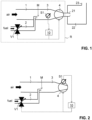
- Figure 1 shows, in a highly schematic manner, a gas burner.
- a gas mixture enters a combustion chamber 22 through one or more burner nozzles 21. Flue gas exits the combustion chamber through an exhaust 23.
- the regulation device R comprises an air conduit 1, through which air enters the regulation device, and a fuel gas conduit 2, through which a fuel gas, for instance a natural gas, enters the regulation device.
- the fuel gas flow in the fuel gas conduit 2 is regulated by an adjusting device in the form of a fuel control valve V1.
- the fuel gas conduit 2 opens out into the air conduit 1 to form a combustible gas mixture consisting of the fuel gas and air.
- the portion of the air conduit 1 that is downstream from the point of injection of the fuel gas flow into the air flow can be considered a common conduit 3 for the gas mixture.
- a fan 4 is arranged at the downstream end of common conduit 3 to transport the gas mixture from common conduit 3 to burner nozzle 21.
- a first sensor S1 for determining one or more thermal parameters of the gas mixture is arranged in common conduit 3 downstream from mixing region M and upstream of fan 4 such that sensor S1 is exposed to the gas mixture.
- sensor S1 is arranged and/or configured in such a manner that the directed flow of the gas mixture in the common conduit 3 does not directly pass over sensor S1.
- sensor S1 may be received in a dead-ended recess in a side wall of common conduit 3.
- sensor S1 may be protected by a permeable membrane allowing only for diffusive gas exchange between common conduit 3 and sensor S1, thereby preventing a directed flow of the gas mixture over sensor S1.
- a control device 10 receives sensor signals from first sensor S1. Based on the sensor signals, control device 10 derives control signals for adjusting the degree of opening of fuel control valve V1. Control device 10 further adjusts the electric power with which fan 4 is operated.
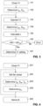
- Figure 2 illustrates an alternative embodiment of a regulation device.
- first sensor S1 is integrated into fan 4, i.e., it is contained within the housing of fan 4.
- sensor S1 may be arranged downstream from fan 4.
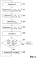
- Figure 3 illustrates a method of regulating the mixing ratio of a gas mixture according to a first embodiment, using a regulation device as illustrated in Figs. 1 or 2 .
- step 101 fuel control valve V1 is closed while fan 4 is operated at some predetermined fan power or fan speed to cause a flow of air through air conduit 1 and common conduit 3.
- step 102 first sensor S1 is operated to determine the thermal conductivity ⁇ air and the thermal diffusivity D air of the air that now passes through common conduit 3.
- step 103 fuel control valve V1 is opened to admit a fuel gas flow into the air flow.
- step 104 first sensor S1 is operated to determine the thermal conductivity ⁇ mix and the thermal diffusivity D mix of the resulting gas mixture.
- the mixing ratio x of the gas mixture is determined. This can be done as follows.
- ⁇ air and ⁇ mix are known from the measurements in steps 102 and 104.
- the value of ⁇ fuel is not directly measured; however, a predetermined value for a representative fuel gas (e.g., an "average" natural gas) may be used.
- thermal diffusivities do not enter Eq. (2), i.e., the thermal diffusivities provide redundant information.
- a consistency check is carried out in step 106 by checking whether the measured value of the thermal diffusivity D mix corresponds to the expected value as calculated by Eq. (3), using the value of the mixing ratio x as determined by Eq. (2).
- a predetermined value of D fuet for a representative fuel gas may be used. If the difference ⁇ D between the measured and calculated values of D mix exceeds a threshold ⁇ D max , an error message is outputted by the control device 10, and the fuel control valve V1 is closed as a safety measure.
- step 107 a control algorithm is carried out, wherein the actual mixing ratio as determined from the sensor signals of sensor S1 (the process variable of the control algorithm) is compared to a desired mixing ratio (the set point of the control algorithm), and a new setting of the gas control valve V1 is accordingly determined.
- Any known control algorithm can be employed, e.g., the well-known proportional-integral-differential (PID) control algorithm.
- step 103 fuel control valve V1 is operated in accordance with the new setting.
- the values of the thermal conductivity ⁇ air and the thermal diffusivity D air of the air in the common conduit 3 as determined in step 102 can be used to determine the density ⁇ air and/or the pressure p air of the air as follows.
- first sensor S1 may be operated in an absolute temperature mode, or a separate temperature sensor (not shown) may be provided in air conduit 1 and/or common conduit 3.
- a humidity sensor may be provided in air conduit 1 and/or in common conduit 3 for determining the relative humidity of the air in order to be able to apply such corrections.
- the air density ⁇ air or air pressure p air determined in this manner can be used as a further diagnostic parameter.
- the air density ⁇ air or air pressure p air can be used to detect a malfunction of the fan 4 or a blockage of the air conduit 1 or the common conduit 3.
- step 201 fuel control valve V1 is closed.
- step 202 the electric power provided to fan 4 is set to some non-zero value. As a result, air will pass through common conduit 3.
- step 203 the thermal conductivity ⁇ air , the thermal diffusivity D air and the air temperature T air of the air at this fan power are determined, using first sensor S1.
- step 204 the air pressure p air or the air density is determined from these parameters, as described above. This procedure is systematically repeated for a predetermined number of different fan powers. The dependence of the air pressure p air or air density on fan power is then compared to an expected dependence to obtain a blockage parameter B.
- blockage parameter B may correspond to the slope of a best-fit line obtained by a linear regression analysis of data pairs corresponding to measured air pressure p air vs. associated fan power.
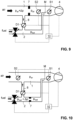
- an optional swirl element 5 is provided in the common conduit 1 downstream from the mixing region M and/or in the mixing region M.
- the swirl element acts to create turbulence in order to improve homogeneity of the air-fuel mixture.
- Further sensors may be provided in air conduit 1 and/or in fuel conduit 2. This is also illustrated in Fig. 5 .
- a second sensor S2 is provided in air conduit 1 upstream of the mixing region M.
- a third sensor S3 is provided in fuel conduit 2 downstream from fuel control valve V1 and upstream of the mixing region M.
- first sensor S1 also second and/or third sensors S2, S3 are advantageously protected from direct exposure to the respective gas flows by disposing each sensor in a dead-ended recess of the wall of the respective conduit, and/or by protecting each sensor by a gas-permeable membrane.
- Fig. 6 illustrates a possible method of regulating the mixing ratio using sensor S1 as well as sensors S2 and S3.
- step 301 fuel control valve V1 is operated to provide a non-zero flow of the fuel gas.
- step 302 sensor S1 is operated to determine the thermal conductivity ⁇ mix , the thermal diffusivity D mix and the temperature T mix of the gas mixture in common conduit 3 downstream from the mixing region M.
- step 303 sensor S2 is operated to determine the thermal conductivity ⁇ air , the thermal diffusivity D air and the temperature T air of the air in air conduit 1 upstream of the mixing region M.
- the air pressure p air is determined from these quantities.
- the air pressure p air or the air density as determined from the signals of sensor S2 can be used as an additional diagnostic parameter.
- the air pressure p air or air density can be used to detect blockages or malfunctions of the fan 4.
- the air pressure or density can be permanently or periodically monitored during operation of the regulation device. Changes in air pressure or density during operation of the fan at constant fan power may indicate a blockage or fan malfunction.
- determination of the air pressure or density from the signals of sensor S2 is possible even during normal operation of the regulation device, whereas in the embodiment described above in conjunction with Fig. 4 , blockages and malfunctions can be detected only while the fuel supply is stopped.
- step 305 sensor S3 is operated to determine the thermal conductivity ⁇ fuel , the thermal diffusivity D fuel and the temperature T fuel of the fuel gas in fuel conduit 2 downstream from fuel control valve V1 and upstream of mixing region M.
- step 306 the mixing ratio x is determined, based on Eq. (3), using the values of ⁇ mix as determined by sensor S1, of ⁇ air as determined by sensor S2, and of ⁇ fuel as determined by sensor S3. If sensor S2 is omitted, it is instead possible to use the value of ⁇ air as determined by sensor S1 while the gas control valve is closed, as described in conjunction with Fig. 3 . If sensor S3 is omitted, it is possible to use the value of ⁇ fuel as determined beforehand for a typical fuel gas.
- a first consistency check is carried out by determining whether the measured value of the thermal diffusivity D mix corresponds to the expected value as calculated by Eq. (3), using the value of the mixing ratio x as determined by Eq. (2), as already described in conjunction with Fig. 3 .
- the actual values of the thermal diffusivities of the oxygen carrier gas and of the fuel gas, as determined by sensors S2 and S3, can be used for this consistency check. If the absolute value of the difference ⁇ D between the measured and calculated values of D mix exceeds a threshold ⁇ D max , an error message is outputted by the control device 10, and fuel control valve V1 is closed as a safety measure.
- This consistency check is particularly powerful if sensors S1 and S2 are mounted on a common carrier that is heat conducting, such as a common printed circuit board.
- a third consistency check is carried out by checking whether the air pressure p air as determined from the signals of sensor S2 indicates a blockage or a malfunction of the fan, as described above. If this is the case, again an error message is outputted by the control device 10, and the fuel control valve V1 is closed as a safety measure.
- step 308 a control algorithm is carried out to derive control signals for fuel control valve V1, as described above in conjunction with step 107 in the embodiment of Fig. 3 .
- sensor S2 is used for determining the value of ⁇ air , the influence of any parameters that affect the output of both sensors S1 and S2, such as the relative humidity of the air, is largely cancelled when forming the difference ⁇ mix - ⁇ air .
- the mixing ratio i.e., the fuel concentration in the gas mixture
- any change of ⁇ air will be reflected by an almost identical change of ⁇ mix. In this manner more precise control of the mixing ratio can be achieved.
- the regulation device becomes adaptive to the fuel gas.
- the determination of the mixing ratio takes into account the real value of ⁇ fuel rather than some predetermined value for a representative fuel gas. This improves accuracy of the control of the mixing ratio.
- ⁇ fuel , D fuel and T fuel and optionally by taking into account the pressure p air obtained by sensor S2 (assuming that the pressures in air conduit 1 and in fuel conduit 2 are approximately equal), it becomes possible to precisely characterize the fuel gas.
- a mass flow meter 6 is arranged in the air conduit 1 upstream of the mixing region M.
- Mass flow meter 6 comprises a flow restrictor 7 in the air conduit 1 and a narrow bypass channel 8 that bypasses the flow restrictor 7.
- a flow sensor D1 measures a flow rate or flow velocity through the bypass channel 8, which flow rate/velocity is indicative of the differential pressure across the flow restrictor 7.
- the flow sensor D thus acts as a differential pressure sensor. Said differential pressure, in turn, is indicative of the mass flow through the flow restrictor 7.
- a similarly designed mass flow meter 6 is arranged in the fuel conduit 2.
- the mass flow rate in the air conduit 1 can also be determined by arranging a flow restrictor 7 in the air conduit 1 upstream from the mixing region M and measuring a differential pressure ⁇ p between the air conduit 1 upstream of the flow restrictor 7 and the fuel conduit 2, using a narrow bypass channel 8 between these conduits.
- the differential pressure corresponds to the pressure across flow restrictor 7, assuming that the pressure p air in the air conduit 1 downstream from the flow restrictor 7 is the same as the pressure p fuel in the fuel conduit 2.
- the mass flow rate in the fuel conduit 2 can be determined by arranging a flow restrictor 7 in the fuel conduit 2 upstream from the mixing region M and measuring differential pressure ⁇ p between the fuel conduit 2 upstream of the flow restrictor 7 and the air conduit 1.
- microthermal sensors that are capable of determining thermal parameters indicative of thermal conductivity and thermal diffusivity are well known in the art.
- a microthermal sensor is employed.
- Many types of microthermal sensors are known, and the present invention is not restricted to any specific type of microthermal sensor.
- the microthermal sensor comprises a substrate 31, in particular a silicon substrate.
- the substrate 31 has an opening or recess 32 arranged therein.
- the microthermal sensor comprises a plurality of separate bridges that span this opening or recess 32.
- EP 3 367 087 A2 For details, reference is made to EP 3 367 087 A2 .
- the microthermal sensor comprises a heating bridge 33, a first sensing bridge 35 and a second sensing bridge 36, each bridge spanning the recess or opening 2 and being anchored in the substrate 1.
- Each bridge may be formed by a plurality of dielectric layers, metal layers and poly-silicon layers.
- the metal layers or the poly-silicon layers form heating structures and temperature sensors, as will be described in more detail below.
- the dielectric layers may in particular comprise layers of silicon oxide and/or silicon nitride as dielectric base materials of the respective bridges.
- the sensing bridges 35, 36 are arranged at opposite sides of the heating bridge 33.
- the first sensing bridge 35 is arranged at a distance d1 to the heating bridge 33
- the second sensing bridge 36 is arranged at the same distance or at a different distance d2 to the heating bridge 33.
- the heating bridge 33 comprises a heating structure 34 and a temperature sensor TS1 applied to a dielectric base material of e.g. silicon oxide.
- the heating structure 34 and the temperature sensor TS1 are electrically insulated from each other by the dielectric base material.
- the first sensing bridge 35 comprises a temperature sensor TS2.
- the second sensing bridge 36 comprises a temperature sensor TS3.
- the temperature sensor TS1 is adapted to measure the temperature of the heating bridge 33
- the temperature sensor TS2 is adapted to measure the temperature of the first sensing bridge 35
- the temperature sensor TS3 is adapted to measure the temperature of the second sensing bridge 36.
- the microthermal sensor further comprises control circuitry 37a, 37b for controlling the operation of the microthermal sensor.
- the control circuitry 37a, 37b may be embodied as integrated circuitry on substrate 31. It includes circuitry for driving the heating structure 34 and for processing signals from the temperature sensors TS1, TS2 and TS3. To this end, the control circuitry 37a, 37b is electrically connected to the heating structure 34 and the temperature sensors TS1, TS2 and TS3 via interconnect circuitry 38.
- control circuitry 37a, 37b is integrated on substrate 31 in CMOS technology. Having the CMOS circuitry integrated on substrate 31 allows to reduce the number of bonds to the substrate and to increase signal-to-noise ratio. Structures of the type shown in Fig. 11 can e.g. be built using techniques such as described in EP 2 278 308 or US 2014/0208830 .
- the thermal conductivity ⁇ and the volumetric heat capacity c p ⁇ of a gas to which the sensor is exposed can be determined in the manner described in EP 3 367 087 A2 .
- the thermal conductivity ⁇ can be determined by operating heating structure 34 to heat up to a steady-state temperature, which can be measured by temperature sensor TS1, and determining the steady-state temperatures at temperature sensors TS2 and/or TS3.
- the steady-state temperatures at sensors TS2 and TS3 depend on the thermal conductivity of the gas.
- the volumetric heat capacity c p ⁇ can be determined by measuring the thermal conductivity of the gas at a plurality of different temperatures, determining coefficients of the temperature dependence of the thermal conductivity, and deriving the volumetric heat capacity from these coefficients, using a fitting function. For details, reference is made to EP 3 367 087 A2 .
- each of the temperature sensors TS1, TS2 and TS3 can be operated in the absence of heating power in order to determine the absolute temperature of the gas.
- the different distances d1 and d2 can be used to perform differential measurements in order to eliminate the thermal transitions between the gas and the respective bridge.
- the ratio ( T S 1 - T S 2 )/ T H could be taken as a measure of the thermal conductivity ⁇ , wherein T S 1 denotes the measured temperature at the first sensing bridge 35, T S 2 the measured temperature at the second sensing bridge 36, and T H denotes the heating temperature at the heating bridge 33.
- US 4,944,035 B1 discloses a method of determining the thermal conductivity A and the specific heat capacity c P of a fluid of interest, using a microthermal sensor.
- the microthermal sensor comprises a resistive heater and a temperature sensor coupled by the fluid of interest.
- a pulse of electrical energy is applied to the heater of a level and duration such that both a transient change and a substantially steady-state temperature occur in the temperature sensor.
- the thermal conductivity of the fluid of interest is determined based upon a known relation between the temperature sensor output and thermal conductivity at steady-state sensor temperature.
- the specific heat capacity is determined based upon a known relation among the thermal conductivity, the rate of change of the temperature sensor output during a transient temperature change in the sensor, and the specific heat capacity.
- US 6,019,505 B1 discloses a method for determining the thermal conductivity, the thermal diffusivity and the specific heat capacity of a fluid of interest, using a microthermal sensor.
- the microthermal sensor comprises a heater and a spaced temperature sensor, both coupled to the fluid of interest.
- a time-variable input signal is provided to the heater element, which heats the surrounding fluid.
- Variable phase or time lags between selected input and output AC signals are measured, and thermal conductivity, thermal diffusivity and specific heat capacity are determined therefrom.
- FIG. 12 A simplified and highly schematic block diagram of a digital control device 500 is shown in Fig. 12 .
- the control device comprises a processor (CPU) ⁇ P, a volatile (RAM) memory 52, and a non-volatile (e.g., Flash ROM) memory 53, and.
- the processor ⁇ P communicates with the memory devices 52, 53 via a data bus 51.
- the non-volatile memory 53 stores, inter alia, plural sets of calibration data for the various sensors.
- Fig. 12 only two exemplary sets of calibration data 54, 55 in the form of lookup tables LUT1, LUT2 are illustrated.
- the lookup tables can correlate, for instance, temperature values determined by the temperature sensors of the microthermal sensors to thermal parameters such as thermal conductivity or thermal diffusivity.
- the non-volatile memory 53 further stores a machine-executable program 56 for execution in the processor ⁇ P.
- the control device Via a device interface IF, the control device communicates with the various sensors S1, S2, S3 and/or D1.
- the device interface further provides an interface for communicating with the fan 4 and with the fuel control valve VI, and with input/output devices I/O such as a keyboard and/or mouse, an LCD screen, etc.
- air conduit 1 may carry a flow of another oxygen carrier gas than air.
- air conduit 1 may carry a mixture of air with flue (exhaust) gas.
- the fuel gas can be any combustible gas.
- the fuel gas is a natural gas.
- the mixing of the oxygen carrier gas and the fuel gas can be carried out in a different manner than illustrated.
- the fuel gas may be injected into the oxygen carrier gas stream through a plurality of injection nozzles, which can be arbitrarily arranged, or the mixing can be carried out using a dedicated mixer.
- the presently disclosed regulation device can be used not only in the context of a gas burner, but also in other applications where a mixture of a fuel gas and an oxygen carrier gas is required, such as in an internal combustion engine (gas motor or gas turbine).
- fan 4 may be arranged at the upstream end of air conduit 1.
- Any type of fan that is able to create a gas stream may be used, for instance, radial or axial fans as they are well known in the art.
- the control device 10 may be configured to not only control the fuel control valve VI, but also to control the fan power.
- An air valve or air flap may be present in the air conduit to additionally regulate the flow of the oxygen carrier gas through air conduit 1, and the control device 10 may be configured to also control the air valve or air flap.
- the sensors S1, S2, S3 determine thermal conductivity and thermal diffusivity.
- the sensors determine any other thermal parameters that are related to thermal conductivity and thermal diffusivity, as long as it is possible to derive thermal conductivity and/or thermal diffusivity from the thermal parameters that are determined by the sensors.
- the mixing ratio is controlled based on measurements of thermal conductivity.
- the mixing ratio x is explicitly determined from the measured thermal parameters and is used as the process variable in the control algorithm for regulating the fuel and/or air flows. This is, however, not necessary.
- the process variable of the control algorithm can be directly one of the thermal parameters determined by sensor S1 or a quantity derived therefrom, for instance, the thermal conductivity difference ⁇ mix - ⁇ air .
- the set point of the control algorithm then is a desired value of this difference. This set point can be predetermined or calculated from one or more of ⁇ fuel , D fuel , T fuel , ⁇ air , p air , T air and T mix .
- the regulation device may be used for regulating entirely different kinds of binary mixtures of two gases.
- the gases can be termed a carrier gas and a functional gas.
- the air conduit of the above embodiment may thus be more generally be regarded as an example of a first conduit for the carrier gas, and the fuel conduit may be regarded as an example of a second conduit for the functional gas.
- the regulation device may be configured to regulate a mixture of an oxygen carrier gas and a medical gas, such as a gaseous anesthetic.
Landscapes
- Engineering & Computer Science (AREA)
- Chemical & Material Sciences (AREA)
- Combustion & Propulsion (AREA)
- Mechanical Engineering (AREA)
- General Engineering & Computer Science (AREA)
- Regulation And Control Of Combustion (AREA)
- Investigating Or Analyzing Materials Using Thermal Means (AREA)
Claims (13)
- Un dispositif de régulation configuré pour réguler un rapport de mélange (x) d'un mélange gazeux, comprenant un premier gaz et un deuxième gaz,dans lequel le premier gaz est de l'air ou un mélange d'air et de gaz d'échappement, et dans lequel le deuxième gaz est un gaz de carburant, oudans lequel le premier gaz est de l'air naturel, de l'air enrichi en oxygène, ou tout autre mélange d'oxygène avec un ou plusieurs gaz inertes, ou un gaz d'oxygène pur, et dans lequel le deuxième gaz est un gaz médical,le dispositif comprenant:un premier conduit (1) pour acheminer un flux du premier gaz;un deuxième conduit (2) pour acheminer un flux d'un deuxième gaz, le premier et le deuxième conduits (1, 2) débouchant dans un conduit commun (3) dans une zone de mélange (M) afin de former un mélange gazeux;un dispositif d'ajustement (V1) pour ajuster le rapport de mélange (x) du mélange gazeux;un dispositif de commande (10) configuré pour dériver des signaux de commande pour le dispositif d'ajustement (V1) ; etun premier capteur (S1) configuré pour déterminer au moins un paramètre thermique du mélange gazeux en aval de la zone de mélange (M), le paramètre thermique étant un paramètre indicatif de la conductivité thermique, de la diffusivité thermique, de la capacité thermique massique ou de la capacité thermique volumique du mélange de gaz, ou de toute combinaison de celles-ci,dans lequel le dispositif de commande (10) est configuré pour recevoir, du premier capteur (S1), des signaux de capteur indicatifs de l'au moins un paramètre thermique du mélange gazeux et pour dériver les signaux de commande pour le dispositif d'ajustement (V1) sur la base de l'au moins un paramètre thermique, etdans lequel le dispositif de commande (10) est configuré pour effectuer la procédure suivante:régler le dispositif d'ajustement à un état de référence dans lequel l'écoulement du second gaz est interrompu tandis que l'écoulement du premier gaz a un débit non nul;recevoir des signaux de capteur du premier capteur (S1), les signaux de capteur étant indicatifs d'au moins un paramètre thermique du premier gaz dans l'état de référence;régler le dispositif d'ajustement à un état de fonctionnement dans lequel à la fois l'écoulement du second gaz et l'écoulement du premier gaz ont des débits non nuls;recevoir des signaux de capteur du premier capteur (S1), les signaux de capteur étant indicatifs d'au moins un paramètre thermique du mélange gazeux dans l'état de fonctionnement; etdériver les signaux de commande sur la base d'une comparaison de l'au moins un paramètre thermique du mélange gazeux dans l'état de fonctionnement et de l'au moins un paramètre thermique du premier gaz dans l'état de référence.
- Le dispositif de régulation selon la revendication 1, dans lequel le second gaz est un anesthésique.
- Le dispositif de régulation selon la revendication 1 ou 2,dans lequel le premier capteur (S1) est configuré pour déterminer au moins deux paramètres thermiques du mélange gazeux, les paramètres thermiques étant ensemble indicatifs de la conductivité thermique (λmélange) et la diffusivité thermique (Dmélange) du mélange gazeux, etdans lequel le dispositif de commande (10) est configuré pour prendre en compte lesdits au moins deux paramètres thermiques.
- Le dispositif de régulation selon la revendication 3, dans lequel le dispositif de commande est configuré pour dériver les signaux de commande sur la base de l'un des paramètres thermiques déterminés par le premier capteur (S1), et pour effectuer un contrôle de cohérence sur la base d'un autre des paramètres thermiques déterminés par le premier capteur (S1).
- Le dispositif de régulation selon la revendication 3 ou 4, dans lequel le dispositif de commande (10) est configuré pour exécuter la procédure suivante:régler le dispositif d'ajustement à un état de référence dans lequel l'écoulement du second gaz est interrompu tandis que l'écoulement du premier gaz a un débit non nul;recevoir des signaux de capteur du premier capteur (S1), les signaux de capteur étant indicatifs des au moins deux paramètres thermiques dans l'état de référence; etsur la base des au moins deux paramètres thermiques dans l'état de référence, déterminer un paramètre de pression (pair) qui est indicatif d'une densité ou une pression du premier gaz dans l'état de référence.
- Le dispositif de régulation selon l'une quelconque des revendications précédentes, comprenant un ventilateur (4) pour transporter le mélange gazeux jusqu'à un point d'utilisation, dans lequel le ventilateur (4) est disposé en aval de la région de mélange, et dans lequel le premier capteur (S1) est intégré dans le ventilateur (4).
- Le dispositif de régulation selon la revendication 6, dans lequel le dispositif de commande (10) est configuré pour exécuter la procédure suivante:faire fonctionner le ventilateur (4) à une pluralité de niveaux de puissance différents pendant que l'écoulement du second gaz est interrompu;pour chaque niveau de puissance, déterminer un paramètre de pression (pair) sur la base des signaux de capteur reçus du premier capteur (S1), le paramètre de pression (pair) étant indicatif de la densité ou la pression du premier gaz audit niveau de puissance; etsur la base des paramètres de pression (pair) à différents niveaux de puissance, dériver un signal de blocage (B) indiquant si un blocage ou un dysfonctionnement du ventilateur s'est produit.
- Le dispositif de régulation selon l'une quelconque des revendications précédentes,comprenant en outre un deuxième capteur (S2), le deuxième capteur (S2) étant configuré pour déterminer au moins un paramètre thermique du premier gaz,dans lequel le dispositif de commande (10) est configuré pour recevoir, du second capteur (S2), des signaux de capteur indicatifs d'au moins un paramètre thermique du premier gaz et pour dériver les signaux de commande sur la base des signaux de capteur reçus à la fois du premier et du second capteurs (S1, S2).
- Le dispositif de régulation selon la revendication 8, dans lequel le deuxième capteur (S2) est configuré pour déterminer au moins deux paramètres thermiques, les au moins deux paramètres thermiques déterminés par le deuxième capteur (S2) étant ensemble indicatifs de la conductivité thermique (λair) et de la diffusivité thermique (Dair) du premier gaz, et
dans lequel le dispositif de commande est configuré pour dériver, sur la base des au moins deux paramètres thermiques déterminés par le deuxième capteur (S2), un paramètre de pression de transport d'oxygène (pair) indicatif de la densité ou de la pression du premier gaz. - Le dispositif de régulation selon la revendication 8 ou 9,dans lequel le premier capteur (S1) est configuré pour déterminer au moins deux paramètres thermiques, les au moins deux paramètres thermiques déterminés par le premier capteur (S1) étant ensemble indicatifs de la conductivité thermique (λmélange) et la diffusivité thermique (Dmélange) du mélange,dans lequel le deuxième capteur (S2) est configuré pour déterminer au moins deux paramètres thermiques, les au moins deux paramètres thermiques déterminés par le deuxième capteur (S2) ensemble étant indicatifs de la conductivité thermique (λair) et la diffusivité thermique (Dair) du premier gaz,dans lequel le dispositif de commande est configuré pour dériver les signaux de commande sur la base d'une comparaison de l'un des paramètres thermiques déterminés par les premier et second capteurs (S1, S2), et pour effectuer un contrôle de cohérence sur la base d'une comparaison d'un autre des au moins deux paramètres thermiques déterminés par les premier et second capteurs (S1, S2).
- Le dispositif de régulation selon l'une quelconque des revendications précédentes, comprenant en outre un troisième capteur (S3), le troisième capteur (S3) étant configuré pour déterminer au moins un paramètre thermique du deuxième gaz,
dans lequel le dispositif de commande (10) est configuré pour recevoir, du troisième capteur (S3), des signaux de capteur indicatifs de l'au moins un paramètre thermique du deuxième gaz et pour dériver les signaux de commande sur la base des signaux de capteur reçus à la fois du premier et des troisièmes capteurs (S1, S3). - Un procédé de régulation d'un rapport de mélange (x) d'un mélange gazeux comprenant un premier gaz et un second gaz,dans lequel le premier gaz est de l'air ou un mélange d'air et gaz d'échappement, et dans lequel le deuxième gaz est un gaz de carburant, oudans lequel le premier gaz est de l'air naturel, de l'air enrichi en oxygène, ou tout autre mélange d'oxygène avec un ou plusieurs gaz inertes, ou un gaz d'oxygène pur, et dans lequel le deuxième gaz est un gaz médical,le procédé comprenant:créer un écoulement du premier gaz;créer un écoulement du deuxième gaz;former le mélange gazeux en mélangeant les écoulements du premier gaz et du second gaz dans une zone de mélange (M),déterminer au moins un paramètre thermique du mélange gazeux en aval de la zone de mélange (M) à l'aide d'un premier capteur (S1), le paramètre thermique étant un paramètre indicatif de la conductivité thermique, de la diffusivité thermique, de la capacité thermique massique ou de la capacité thermique volumique du mélange de gaz, ou de toute combinaison de celles-ci, et
sur la base de l'au moins un paramètre thermique, ajuster de rapport de mélange (x),le procédé comprenant la procédure suivante:créer un état de référence dans lequel l'écoulement du second gaz est interrompu tandis que l'écoulement du premier gaz a un débit non nul;recevoir des signaux de capteur du premier capteur (S1), les signaux de capteur étant indicatifs d'au moins un paramètre thermique du premier gaz dans l'état de référence;créer un état de fonctionnement dans lequel à la fois l'écoulement du second gaz et l'écoulement du premier gaz ont des débits non nuls;recevoir des signaux de capteur du premier capteur (S1), les signaux de capteur étant indicatifs d'au moins un paramètre thermique du mélange gazeux dans l'état de fonctionnement; etajuster le rapport de mélange le sur la base d'une comparaison de l'au moins un paramètre thermique du mélange gazeux dans l'état de fonctionnement et de l'au moins un paramètre thermique du premier gaz dans l'état de référence. - Le procédé selon la revendication 12, dans lequel le second gaz est un anesthésique.
Priority Applications (1)
| Application Number | Priority Date | Filing Date | Title |
|---|---|---|---|
| EP20192454.5A EP3760926B1 (fr) | 2018-10-05 | 2018-10-05 | Dispositif de régulation d'un taux de mélange d'un mélange gazeux |
Applications Claiming Priority (1)
| Application Number | Priority Date | Filing Date | Title |
|---|---|---|---|
| PCT/EP2018/077146 WO2019185181A1 (fr) | 2018-10-05 | 2018-10-05 | Dispositif de régulation d'un taux de mélange d'un mélange gazeux |
Related Child Applications (2)
| Application Number | Title | Priority Date | Filing Date |
|---|---|---|---|
| EP20192454.5A Division EP3760926B1 (fr) | 2018-10-05 | 2018-10-05 | Dispositif de régulation d'un taux de mélange d'un mélange gazeux |
| EP20192454.5A Division-Into EP3760926B1 (fr) | 2018-10-05 | 2018-10-05 | Dispositif de régulation d'un taux de mélange d'un mélange gazeux |
Publications (3)
| Publication Number | Publication Date |
|---|---|
| EP3571443A1 EP3571443A1 (fr) | 2019-11-27 |
| EP3571443B1 EP3571443B1 (fr) | 2020-12-02 |
| EP3571443B2 true EP3571443B2 (fr) | 2024-03-20 |
Family
ID=63832400
Family Applications (2)
| Application Number | Title | Priority Date | Filing Date |
|---|---|---|---|
| EP20192454.5A Active EP3760926B1 (fr) | 2018-10-05 | 2018-10-05 | Dispositif de régulation d'un taux de mélange d'un mélange gazeux |
| EP18785308.0A Active EP3571443B2 (fr) | 2018-10-05 | 2018-10-05 | Dispositif de régulation d'un taux de mélange d'un mélange gazeux |
Family Applications Before (1)
| Application Number | Title | Priority Date | Filing Date |
|---|---|---|---|
| EP20192454.5A Active EP3760926B1 (fr) | 2018-10-05 | 2018-10-05 | Dispositif de régulation d'un taux de mélange d'un mélange gazeux |
Country Status (6)
| Country | Link |
|---|---|
| US (1) | US20210388985A1 (fr) |
| EP (2) | EP3760926B1 (fr) |
| JP (1) | JP7168775B2 (fr) |
| KR (1) | KR20210071044A (fr) |
| CN (1) | CN112805504B (fr) |
| WO (1) | WO2019185181A1 (fr) |
Families Citing this family (5)
| Publication number | Priority date | Publication date | Assignee | Title |
|---|---|---|---|---|
| DE102019101191A1 (de) * | 2019-01-17 | 2020-07-23 | Ebm-Papst Landshut Gmbh | Verfahren zur Regelung eines Gasgemisches unter Nutzung eines Gassensors und eines Gasgemischsensors |
| DE102019101189A1 (de) * | 2019-01-17 | 2020-07-23 | Ebm-Papst Landshut Gmbh | Verfahren zur Regelung eines Gasgemisches |
| DE102019101190A1 (de) | 2019-01-17 | 2020-07-23 | Ebm-Papst Landshut Gmbh | Verfahren zur Regelung eines Gasgemisches unter Nutzung eines Gassensors, eines Brenngassensors und eines Gasgemischsensors |
| EP4047268A1 (fr) | 2021-02-18 | 2022-08-24 | BDR Thermea Group B.V. | Procédé de fonctionnement d'un chauffage au gaz |
| EP4265965A1 (fr) * | 2022-04-22 | 2023-10-25 | BDR Thermea Group B.V. | Mécanisme de commande pour un appareil de combustion |
Citations (2)
| Publication number | Priority date | Publication date | Assignee | Title |
|---|---|---|---|---|
| US20110126545A1 (en) † | 2009-11-30 | 2011-06-02 | General Electric Company | Systems and methods for controlling fuel mixing |
| WO2020030323A1 (fr) † | 2018-08-09 | 2020-02-13 | Ebm-Papst Landshut Gmbh | Procédé pour la régulation d'un rapport de mélange de gaz combustible et d'air pour un appareil de chauffage |
Family Cites Families (39)
| Publication number | Priority date | Publication date | Assignee | Title |
|---|---|---|---|---|
| FI772751A (fi) | 1976-12-14 | 1978-06-15 | Measurex Corp | Foerfarande och anordning foer att kontrollera effektiviteten av foerbraenningen i en ugn |
| US4944035A (en) | 1988-06-24 | 1990-07-24 | Honeywell Inc. | Measurement of thermal conductivity and specific heat |
| GB8924469D0 (en) | 1989-10-31 | 1989-12-20 | Clausen Kaldager & Company As | A gas flow monitoring system |
| US5235844A (en) | 1991-10-23 | 1993-08-17 | Niagara Mohawk Power Corporation | Multiple gas property sensor |
| AU3055992A (en) | 1991-10-23 | 1993-05-21 | Niagara Mohawk Power Corporation | On-line combustionless measurement of gaseous fuels fed to gas consumption devices |
| EP0554095A3 (en) | 1992-01-30 | 1994-12-14 | Honeywell Inc | Determination of fuel characteristics |
| US6019505A (en) | 1997-12-31 | 2000-02-01 | Honeywell Inc. | Time lag approach for measuring thermal conductivity and specific heat |
| DE19824521B4 (de) | 1998-06-02 | 2004-12-23 | Honeywell B.V. | Regeleinrichtung für Gasbrenner |
| DE19857239C2 (de) | 1998-12-11 | 2000-11-23 | Honeywell Bv | Regelverfahren für Gasbrenner |
| DE19918901C1 (de) * | 1999-04-26 | 2001-05-03 | Franz Durst | Vorrichtung zur Einstellung des Oxydationsmittel/Brennstoffgemisches in der Zuleitung eines Brenners |
| US6581599B1 (en) | 1999-11-24 | 2003-06-24 | Sensormedics Corporation | Method and apparatus for delivery of inhaled nitric oxide to spontaneous-breathing and mechanically-ventilated patients |
| DE10032764C2 (de) | 2000-07-05 | 2002-12-12 | Rational Ag | Verfahren zur Leistungsanpassung eines Verbrennungssystems eines Gargerätes sowie ein dieses Verfahren verwendendes Verbrennungssystem |
| ITAN20020038A1 (it) | 2002-08-05 | 2004-02-06 | Merloni Termosanitari Spa Ora Ariston Thermo Spa | Sistema di controllo della combustione a sensore virtuale di lambda. |
| US20050247311A1 (en) | 2002-09-16 | 2005-11-10 | Charles Vacchiano | Reduced-oxygen breathing device |
| JP4011572B2 (ja) | 2004-09-10 | 2007-11-21 | カワサキプラントシステムズ株式会社 | ガス改質設備 |
| KR100875497B1 (ko) | 2004-12-27 | 2008-12-22 | 카와사키 주코교 카부시키 카이샤 | 가스 칼로리 변동 억제 장치, 연료 가스 공급 설비, 가스터빈 설비 및 보일러 설비 |
| KR100875498B1 (ko) | 2005-01-26 | 2008-12-22 | 카와사키 주코교 카부시키 카이샤 | 가스 칼로리 변동 억제 장치, 연료 가스 공급 설비, 가스터빈 설비 및 보일러 설비 |
| JP2006233920A (ja) | 2005-02-28 | 2006-09-07 | Mitsubishi Heavy Ind Ltd | 燃料ガスカロリー制御装置及びガスタービンシステム |
| JP4563242B2 (ja) | 2005-04-19 | 2010-10-13 | 三菱重工業株式会社 | 燃料ガスカロリ制御方法及び装置 |
| EP2183011B1 (fr) | 2007-06-28 | 2017-10-11 | Maquet Critical Care AB | Système de ventilation d'un patient équipé d'un moyen pour identifier un gaz |
| JP5107063B2 (ja) * | 2008-01-08 | 2012-12-26 | アズビル株式会社 | 流量制御装置 |
| JP4921556B2 (ja) | 2008-04-22 | 2012-04-25 | 日本特殊陶業株式会社 | ガスセンサ |
| KR100912148B1 (ko) | 2009-02-25 | 2009-08-14 | 카와사키 주코교 카부시키 카이샤 | 가스 터빈 설비, 연료가스 공급 설비 및 연료가스의 칼로리상승 억제 방법 |
| US8151740B2 (en) | 2009-06-02 | 2012-04-10 | General Electric Company | System and method for controlling the calorie content of a fuel |
| PL2495496T3 (pl) | 2011-03-03 | 2015-10-30 | Siemens Ag | Instalacja palnikowa |
| DE102011079325B4 (de) | 2011-07-18 | 2017-01-26 | Viessmann Werke Gmbh & Co Kg | Verfahren zur Luftzahlregelung eines Brenners |
| EP2574918B1 (fr) | 2011-09-28 | 2014-12-10 | Mems Ag | Procédé et capteur microthermiques pour la détermination de propriétés de gaz physiques |
| EP2762866B1 (fr) | 2013-01-31 | 2017-08-09 | Sensirion AG | Capteur de gaz CMOS et son procédé de fabrication |
| EP2843214B1 (fr) | 2013-05-29 | 2021-06-23 | Mems Ag | Procédé, capteur et dispositif de réglage d'installations de conversion d'énergie fonctionnant au gaz |
| DE102013106987A1 (de) * | 2013-07-03 | 2015-01-08 | Karl Dungs Gmbh & Co. Kg | Verfahren und Vorrichtung zur Bestimmung einer Brennwertgröße sowie gasbetriebene Einrichtung mit einer derartigen Vorrichtung |
| CN203656969U (zh) * | 2013-11-25 | 2014-06-18 | 洛阳安拓窑炉环保有限公司 | 窑炉燃烧控制装置 |
| US10226592B2 (en) | 2014-04-01 | 2019-03-12 | Mallinckrodt Hospital Product Ip Limited | Systems and method for delivery of therapeutic gas to patients in need thereof using enhanced breathing circuit gas (BCG) flow measurement |
| KR101759217B1 (ko) * | 2014-10-31 | 2017-08-01 | 한국생산기술연구원 | 복합센서를 이용한 공연비 제어 시스템 및 제어 방법 |
| DE102015223177A1 (de) | 2015-11-24 | 2017-05-24 | Robert Bosch Gmbh | Heizgerätevorrichtung, insbesondere Gas und/oder Ölbrennervorrichtung, und Verfahren zum Betrieb einer Heizgerätevorrichtung |
| CN106196564A (zh) * | 2016-08-31 | 2016-12-07 | 中山市卡洛力热能科技有限公司 | 一种自调节预混燃气加热系统及其控制方法 |
| DE102016014151A1 (de) * | 2016-11-25 | 2018-05-30 | Diehl Metering Gmbh | Verfahren zur Ermittlung eines Brennwertes und/oder eines Wobbe-Index eines Gasgemisches |
| CN207424721U (zh) * | 2017-11-24 | 2018-05-29 | 泉州装备制造研究所 | 一种co混合气体流量控制设备 |
| DE202018101271U1 (de) * | 2018-03-07 | 2018-03-15 | Ebm-Papst Landshut Gmbh | Brenngasbetriebenes Heizgerät |
| EP3367087A3 (fr) | 2018-04-30 | 2018-12-26 | Sensirion AG | Capteur pour déterminer la capacité thermique de fluides |
-
2018
- 2018-10-05 EP EP20192454.5A patent/EP3760926B1/fr active Active
- 2018-10-05 CN CN201880098415.3A patent/CN112805504B/zh active Active
- 2018-10-05 EP EP18785308.0A patent/EP3571443B2/fr active Active
- 2018-10-05 KR KR1020217013434A patent/KR20210071044A/ko not_active Application Discontinuation
- 2018-10-05 US US17/282,718 patent/US20210388985A1/en active Pending
- 2018-10-05 JP JP2021518165A patent/JP7168775B2/ja active Active
- 2018-10-05 WO PCT/EP2018/077146 patent/WO2019185181A1/fr unknown
Patent Citations (2)
| Publication number | Priority date | Publication date | Assignee | Title |
|---|---|---|---|---|
| US20110126545A1 (en) † | 2009-11-30 | 2011-06-02 | General Electric Company | Systems and methods for controlling fuel mixing |
| WO2020030323A1 (fr) † | 2018-08-09 | 2020-02-13 | Ebm-Papst Landshut Gmbh | Procédé pour la régulation d'un rapport de mélange de gaz combustible et d'air pour un appareil de chauffage |
Also Published As
| Publication number | Publication date |
|---|---|
| JP7168775B2 (ja) | 2022-11-09 |
| EP3760926A1 (fr) | 2021-01-06 |
| WO2019185181A1 (fr) | 2019-10-03 |
| CN112805504A (zh) | 2021-05-14 |
| EP3571443B1 (fr) | 2020-12-02 |
| EP3760926B1 (fr) | 2021-12-01 |
| EP3571443A1 (fr) | 2019-11-27 |
| JP2022505021A (ja) | 2022-01-14 |
| US20210388985A1 (en) | 2021-12-16 |
| KR20210071044A (ko) | 2021-06-15 |
| CN112805504B (zh) | 2024-03-19 |
Similar Documents
| Publication | Publication Date | Title |
|---|---|---|
| EP3571443B2 (fr) | Dispositif de régulation d'un taux de mélange d'un mélange gazeux | |
| US7201071B2 (en) | Wide range continuous diluter | |
| US6939127B2 (en) | Method and device for adjusting air ratio | |
| US8104323B2 (en) | Flow controller, flow measuring device testing method, flow controller testing system, and semiconductor manufacturing apparatus | |
| US7188519B2 (en) | Device and method for measuring the flow and at least one material parameter of a fluid | |
| EP2102623B1 (fr) | Système de comptage de particules solides destiné à réduire les impulsions de pression au niveau du compteur de particules lorsque la pompe à vide est déclenchée | |
| US7647810B2 (en) | Solid particle counting system with flow meter upstream of evaporation unit | |
| EP2241810A1 (fr) | Dispositif de commande de débit d'écoulement | |
| JP5668611B2 (ja) | 内燃機関用制御装置、および内燃機関用制御方法 | |
| EP2993334B1 (fr) | Moteur à gaz | |
| EP2208042B1 (fr) | Unité d'étalonnage pour extracteur de particules volatiles | |
| JP2016020791A (ja) | ボイラ装置 | |
| US20240018921A1 (en) | Combustion Apparatus with Mass Flow Sensor | |
| EP4047268A1 (fr) | Procédé de fonctionnement d'un chauffage au gaz | |
| US8678814B2 (en) | Control system of an internal combustion engine | |
| CN116734285A (zh) | 用于控制预混气体燃烧器的燃料-氧化剂混合物的装置和方法 | |
| JP2001193485A (ja) | ガスタービン・エンジンの制御装置 | |
| JP2002250517A (ja) | ガスタービン燃焼器システムおよびその運用方法 | |
| JP2001193487A (ja) | ガスタービン・エンジンの制御装置 | |
| KR890012158A (ko) | 유동 이송연료의 발연공률 측정방법 및 장치 | |
| KR20060113677A (ko) | 내연기관의 제어 시스템 |
Legal Events
| Date | Code | Title | Description |
|---|---|---|---|
| STAA | Information on the status of an ep patent application or granted ep patent |
Free format text: STATUS: UNKNOWN |
|
| STAA | Information on the status of an ep patent application or granted ep patent |
Free format text: STATUS: THE INTERNATIONAL PUBLICATION HAS BEEN MADE |
|
| PUAI | Public reference made under article 153(3) epc to a published international application that has entered the european phase |
Free format text: ORIGINAL CODE: 0009012 |
|
| STAA | Information on the status of an ep patent application or granted ep patent |
Free format text: STATUS: REQUEST FOR EXAMINATION WAS MADE |
|
| 17P | Request for examination filed |
Effective date: 20190808 |
|
| AK | Designated contracting states |
Kind code of ref document: A1 Designated state(s): AL AT BE BG CH CY CZ DE DK EE ES FI FR GB GR HR HU IE IS IT LI LT LU LV MC MK MT NL NO PL PT RO RS SE SI SK SM TR |
|
| AX | Request for extension of the european patent |
Extension state: BA ME |
|
| STAA | Information on the status of an ep patent application or granted ep patent |
Free format text: STATUS: EXAMINATION IS IN PROGRESS |
|
| 17Q | First examination report despatched |
Effective date: 20200122 |
|
| GRAP | Despatch of communication of intention to grant a patent |
Free format text: ORIGINAL CODE: EPIDOSNIGR1 |
|
| STAA | Information on the status of an ep patent application or granted ep patent |
Free format text: STATUS: GRANT OF PATENT IS INTENDED |
|
| DAV | Request for validation of the european patent (deleted) | ||
| DAX | Request for extension of the european patent (deleted) | ||
| INTG | Intention to grant announced |
Effective date: 20200710 |
|
| GRAS | Grant fee paid |
Free format text: ORIGINAL CODE: EPIDOSNIGR3 |
|
| GRAA | (expected) grant |
Free format text: ORIGINAL CODE: 0009210 |
|
| STAA | Information on the status of an ep patent application or granted ep patent |
Free format text: STATUS: THE PATENT HAS BEEN GRANTED |
|
| AK | Designated contracting states |
Kind code of ref document: B1 Designated state(s): AL AT BE BG CH CY CZ DE DK EE ES FI FR GB GR HR HU IE IS IT LI LT LU LV MC MK MT NL NO PL PT RO RS SE SI SK SM TR |
|
| REG | Reference to a national code |
Ref country code: GB Ref legal event code: FG4D |
|
| REG | Reference to a national code |
Ref country code: AT Ref legal event code: REF Ref document number: 1341334 Country of ref document: AT Kind code of ref document: T Effective date: 20201215 Ref country code: CH Ref legal event code: EP |
|
| REG | Reference to a national code |
Ref country code: IE Ref legal event code: FG4D |
|
| REG | Reference to a national code |
Ref country code: DE Ref legal event code: R096 Ref document number: 602018010473 Country of ref document: DE |
|
| PG25 | Lapsed in a contracting state [announced via postgrant information from national office to epo] |
Ref country code: NO Free format text: LAPSE BECAUSE OF FAILURE TO SUBMIT A TRANSLATION OF THE DESCRIPTION OR TO PAY THE FEE WITHIN THE PRESCRIBED TIME-LIMIT Effective date: 20210302 Ref country code: GR Free format text: LAPSE BECAUSE OF FAILURE TO SUBMIT A TRANSLATION OF THE DESCRIPTION OR TO PAY THE FEE WITHIN THE PRESCRIBED TIME-LIMIT Effective date: 20210303 Ref country code: RS Free format text: LAPSE BECAUSE OF FAILURE TO SUBMIT A TRANSLATION OF THE DESCRIPTION OR TO PAY THE FEE WITHIN THE PRESCRIBED TIME-LIMIT Effective date: 20201202 Ref country code: FI Free format text: LAPSE BECAUSE OF FAILURE TO SUBMIT A TRANSLATION OF THE DESCRIPTION OR TO PAY THE FEE WITHIN THE PRESCRIBED TIME-LIMIT Effective date: 20201202 |
|
| REG | Reference to a national code |
Ref country code: NL Ref legal event code: MP Effective date: 20201202 |
|
| REG | Reference to a national code |
Ref country code: AT Ref legal event code: MK05 Ref document number: 1341334 Country of ref document: AT Kind code of ref document: T Effective date: 20201202 |
|
| PG25 | Lapsed in a contracting state [announced via postgrant information from national office to epo] |
Ref country code: PL Free format text: LAPSE BECAUSE OF FAILURE TO SUBMIT A TRANSLATION OF THE DESCRIPTION OR TO PAY THE FEE WITHIN THE PRESCRIBED TIME-LIMIT Effective date: 20201202 Ref country code: LV Free format text: LAPSE BECAUSE OF FAILURE TO SUBMIT A TRANSLATION OF THE DESCRIPTION OR TO PAY THE FEE WITHIN THE PRESCRIBED TIME-LIMIT Effective date: 20201202 Ref country code: SE Free format text: LAPSE BECAUSE OF FAILURE TO SUBMIT A TRANSLATION OF THE DESCRIPTION OR TO PAY THE FEE WITHIN THE PRESCRIBED TIME-LIMIT Effective date: 20201202 Ref country code: BG Free format text: LAPSE BECAUSE OF FAILURE TO SUBMIT A TRANSLATION OF THE DESCRIPTION OR TO PAY THE FEE WITHIN THE PRESCRIBED TIME-LIMIT Effective date: 20210302 |
|
| PG25 | Lapsed in a contracting state [announced via postgrant information from national office to epo] |
Ref country code: NL Free format text: LAPSE BECAUSE OF FAILURE TO SUBMIT A TRANSLATION OF THE DESCRIPTION OR TO PAY THE FEE WITHIN THE PRESCRIBED TIME-LIMIT Effective date: 20201202 Ref country code: HR Free format text: LAPSE BECAUSE OF FAILURE TO SUBMIT A TRANSLATION OF THE DESCRIPTION OR TO PAY THE FEE WITHIN THE PRESCRIBED TIME-LIMIT Effective date: 20201202 |
|
| REG | Reference to a national code |
Ref country code: LT Ref legal event code: MG9D |
|
| PG25 | Lapsed in a contracting state [announced via postgrant information from national office to epo] |
Ref country code: LT Free format text: LAPSE BECAUSE OF FAILURE TO SUBMIT A TRANSLATION OF THE DESCRIPTION OR TO PAY THE FEE WITHIN THE PRESCRIBED TIME-LIMIT Effective date: 20201202 Ref country code: RO Free format text: LAPSE BECAUSE OF FAILURE TO SUBMIT A TRANSLATION OF THE DESCRIPTION OR TO PAY THE FEE WITHIN THE PRESCRIBED TIME-LIMIT Effective date: 20201202 Ref country code: PT Free format text: LAPSE BECAUSE OF FAILURE TO SUBMIT A TRANSLATION OF THE DESCRIPTION OR TO PAY THE FEE WITHIN THE PRESCRIBED TIME-LIMIT Effective date: 20210405 Ref country code: CZ Free format text: LAPSE BECAUSE OF FAILURE TO SUBMIT A TRANSLATION OF THE DESCRIPTION OR TO PAY THE FEE WITHIN THE PRESCRIBED TIME-LIMIT Effective date: 20201202 Ref country code: EE Free format text: LAPSE BECAUSE OF FAILURE TO SUBMIT A TRANSLATION OF THE DESCRIPTION OR TO PAY THE FEE WITHIN THE PRESCRIBED TIME-LIMIT Effective date: 20201202 Ref country code: SK Free format text: LAPSE BECAUSE OF FAILURE TO SUBMIT A TRANSLATION OF THE DESCRIPTION OR TO PAY THE FEE WITHIN THE PRESCRIBED TIME-LIMIT Effective date: 20201202 Ref country code: SM Free format text: LAPSE BECAUSE OF FAILURE TO SUBMIT A TRANSLATION OF THE DESCRIPTION OR TO PAY THE FEE WITHIN THE PRESCRIBED TIME-LIMIT Effective date: 20201202 |
|
| PG25 | Lapsed in a contracting state [announced via postgrant information from national office to epo] |
Ref country code: AT Free format text: LAPSE BECAUSE OF FAILURE TO SUBMIT A TRANSLATION OF THE DESCRIPTION OR TO PAY THE FEE WITHIN THE PRESCRIBED TIME-LIMIT Effective date: 20201202 |
|
| REG | Reference to a national code |
Ref country code: DE Ref legal event code: R026 Ref document number: 602018010473 Country of ref document: DE |
|
| PLBI | Opposition filed |
Free format text: ORIGINAL CODE: 0009260 |
|
| PLAX | Notice of opposition and request to file observation + time limit sent |
Free format text: ORIGINAL CODE: EPIDOSNOBS2 |
|
| PG25 | Lapsed in a contracting state [announced via postgrant information from national office to epo] |
Ref country code: IS Free format text: LAPSE BECAUSE OF FAILURE TO SUBMIT A TRANSLATION OF THE DESCRIPTION OR TO PAY THE FEE WITHIN THE PRESCRIBED TIME-LIMIT Effective date: 20210402 |
|
| 26 | Opposition filed |
Opponent name: SIT S.P.A. Effective date: 20210901 |
|
| PG25 | Lapsed in a contracting state [announced via postgrant information from national office to epo] |
Ref country code: AL Free format text: LAPSE BECAUSE OF FAILURE TO SUBMIT A TRANSLATION OF THE DESCRIPTION OR TO PAY THE FEE WITHIN THE PRESCRIBED TIME-LIMIT Effective date: 20201202 |
|
| PG25 | Lapsed in a contracting state [announced via postgrant information from national office to epo] |
Ref country code: DK Free format text: LAPSE BECAUSE OF FAILURE TO SUBMIT A TRANSLATION OF THE DESCRIPTION OR TO PAY THE FEE WITHIN THE PRESCRIBED TIME-LIMIT Effective date: 20201202 Ref country code: SI Free format text: LAPSE BECAUSE OF FAILURE TO SUBMIT A TRANSLATION OF THE DESCRIPTION OR TO PAY THE FEE WITHIN THE PRESCRIBED TIME-LIMIT Effective date: 20201202 |
|
| PLBB | Reply of patent proprietor to notice(s) of opposition received |
Free format text: ORIGINAL CODE: EPIDOSNOBS3 |
|
| PG25 | Lapsed in a contracting state [announced via postgrant information from national office to epo] |
Ref country code: ES Free format text: LAPSE BECAUSE OF FAILURE TO SUBMIT A TRANSLATION OF THE DESCRIPTION OR TO PAY THE FEE WITHIN THE PRESCRIBED TIME-LIMIT Effective date: 20201202 |
|
| PG25 | Lapsed in a contracting state [announced via postgrant information from national office to epo] |
Ref country code: IS Free format text: LAPSE BECAUSE OF FAILURE TO SUBMIT A TRANSLATION OF THE DESCRIPTION OR TO PAY THE FEE WITHIN THE PRESCRIBED TIME-LIMIT Effective date: 20210402 |
|
| REG | Reference to a national code |
Ref country code: BE Ref legal event code: MM Effective date: 20211031 |
|
| PG25 | Lapsed in a contracting state [announced via postgrant information from national office to epo] |
Ref country code: MC Free format text: LAPSE BECAUSE OF FAILURE TO SUBMIT A TRANSLATION OF THE DESCRIPTION OR TO PAY THE FEE WITHIN THE PRESCRIBED TIME-LIMIT Effective date: 20201202 |
|
| PG25 | Lapsed in a contracting state [announced via postgrant information from national office to epo] |
Ref country code: LU Free format text: LAPSE BECAUSE OF NON-PAYMENT OF DUE FEES Effective date: 20211005 Ref country code: BE Free format text: LAPSE BECAUSE OF NON-PAYMENT OF DUE FEES Effective date: 20211031 |
|
| PG25 | Lapsed in a contracting state [announced via postgrant information from national office to epo] |
Ref country code: IE Free format text: LAPSE BECAUSE OF NON-PAYMENT OF DUE FEES Effective date: 20211005 |
|
| PG25 | Lapsed in a contracting state [announced via postgrant information from national office to epo] |
Ref country code: CY Free format text: LAPSE BECAUSE OF FAILURE TO SUBMIT A TRANSLATION OF THE DESCRIPTION OR TO PAY THE FEE WITHIN THE PRESCRIBED TIME-LIMIT Effective date: 20201202 |
|
| P01 | Opt-out of the competence of the unified patent court (upc) registered |
Effective date: 20230602 |
|
| PG25 | Lapsed in a contracting state [announced via postgrant information from national office to epo] |
Ref country code: HU Free format text: LAPSE BECAUSE OF FAILURE TO SUBMIT A TRANSLATION OF THE DESCRIPTION OR TO PAY THE FEE WITHIN THE PRESCRIBED TIME-LIMIT; INVALID AB INITIO Effective date: 20181005 |
|
| APBM | Appeal reference recorded |
Free format text: ORIGINAL CODE: EPIDOSNREFNO |
|
| APBP | Date of receipt of notice of appeal recorded |
Free format text: ORIGINAL CODE: EPIDOSNNOA2O |
|
| APAH | Appeal reference modified |
Free format text: ORIGINAL CODE: EPIDOSCREFNO |
|
| APBU | Appeal procedure closed |
Free format text: ORIGINAL CODE: EPIDOSNNOA9O |
|
| PGFP | Annual fee paid to national office [announced via postgrant information from national office to epo] |
Ref country code: GB Payment date: 20231025 Year of fee payment: 6 |
|
| PGFP | Annual fee paid to national office [announced via postgrant information from national office to epo] |
Ref country code: IT Payment date: 20231031 Year of fee payment: 6 Ref country code: FR Payment date: 20231023 Year of fee payment: 6 Ref country code: DE Payment date: 20231018 Year of fee payment: 6 Ref country code: CH Payment date: 20231102 Year of fee payment: 6 |
|
| PUAH | Patent maintained in amended form |
Free format text: ORIGINAL CODE: 0009272 |
|
| STAA | Information on the status of an ep patent application or granted ep patent |
Free format text: STATUS: PATENT MAINTAINED AS AMENDED |
|
| 27A | Patent maintained in amended form |
Effective date: 20240320 |
|
| AK | Designated contracting states |
Kind code of ref document: B2 Designated state(s): AL AT BE BG CH CY CZ DE DK EE ES FI FR GB GR HR HU IE IS IT LI LT LU LV MC MK MT NL NO PL PT RO RS SE SI SK SM TR |
|
| REG | Reference to a national code |
Ref country code: DE Ref legal event code: R102 Ref document number: 602018010473 Country of ref document: DE |
|
| PG25 | Lapsed in a contracting state [announced via postgrant information from national office to epo] |
Ref country code: MK Free format text: LAPSE BECAUSE OF FAILURE TO SUBMIT A TRANSLATION OF THE DESCRIPTION OR TO PAY THE FEE WITHIN THE PRESCRIBED TIME-LIMIT Effective date: 20201202 |