EP3570466B1 - Procédé et dispositifs pour la transmission de signaux client dans un réseau de transport optique - Google Patents
Procédé et dispositifs pour la transmission de signaux client dans un réseau de transport optique Download PDFInfo
- Publication number
- EP3570466B1 EP3570466B1 EP19170196.0A EP19170196A EP3570466B1 EP 3570466 B1 EP3570466 B1 EP 3570466B1 EP 19170196 A EP19170196 A EP 19170196A EP 3570466 B1 EP3570466 B1 EP 3570466B1
- Authority
- EP
- European Patent Office
- Prior art keywords
- opuk
- frame
- client signal
- client
- tss
- Prior art date
- Legal status (The legal status is an assumption and is not a legal conclusion. Google has not performed a legal analysis and makes no representation as to the accuracy of the status listed.)
- Active
Links
- 238000000034 method Methods 0.000 title claims abstract description 49
- 230000003287 optical effect Effects 0.000 title claims description 32
- 238000013507 mapping Methods 0.000 claims abstract description 129
- 101150014732 asnS gene Proteins 0.000 description 90
- 230000005540 biological transmission Effects 0.000 description 21
- 239000000835 fiber Substances 0.000 description 15
- 238000012546 transfer Methods 0.000 description 7
- 230000001360 synchronised effect Effects 0.000 description 6
- 102100023927 Asparagine synthetase [glutamine-hydrolyzing] Human genes 0.000 description 4
- 101100380329 Homo sapiens ASNS gene Proteins 0.000 description 4
- 238000005516 engineering process Methods 0.000 description 4
- 239000000284 extract Substances 0.000 description 4
- 238000004891 communication Methods 0.000 description 3
- 101100406674 Arabidopsis thaliana OTU4 gene Proteins 0.000 description 2
- 238000011161 development Methods 0.000 description 2
- 230000006870 function Effects 0.000 description 2
- 238000012986 modification Methods 0.000 description 2
- 230000004048 modification Effects 0.000 description 2
- 101100341026 Caenorhabditis elegans inx-2 gene Proteins 0.000 description 1
- 101100341029 Caenorhabditis elegans inx-3 gene Proteins 0.000 description 1
- OKKRPWIIYQTPQF-UHFFFAOYSA-N Trimethylolpropane trimethacrylate Chemical compound CC(=C)C(=O)OCC(CC)(COC(=O)C(C)=C)COC(=O)C(C)=C OKKRPWIIYQTPQF-UHFFFAOYSA-N 0.000 description 1
- 101100438139 Vulpes vulpes CABYR gene Proteins 0.000 description 1
- 230000006978 adaptation Effects 0.000 description 1
- 238000013459 approach Methods 0.000 description 1
- 238000012937 correction Methods 0.000 description 1
- 238000009432 framing Methods 0.000 description 1
Images


Classifications
-
- H—ELECTRICITY
- H04—ELECTRIC COMMUNICATION TECHNIQUE
- H04J—MULTIPLEX COMMUNICATION
- H04J3/00—Time-division multiplex systems
- H04J3/16—Time-division multiplex systems in which the time allocation to individual channels within a transmission cycle is variable, e.g. to accommodate varying complexity of signals, to vary number of channels transmitted
- H04J3/1605—Fixed allocated frame structures
- H04J3/1652—Optical Transport Network [OTN]
- H04J3/1658—Optical Transport Network [OTN] carrying packets or ATM cells
-
- H—ELECTRICITY
- H04—ELECTRIC COMMUNICATION TECHNIQUE
- H04J—MULTIPLEX COMMUNICATION
- H04J3/00—Time-division multiplex systems
- H04J3/16—Time-division multiplex systems in which the time allocation to individual channels within a transmission cycle is variable, e.g. to accommodate varying complexity of signals, to vary number of channels transmitted
- H04J3/1605—Fixed allocated frame structures
- H04J3/1652—Optical Transport Network [OTN]
- H04J3/1664—Optical Transport Network [OTN] carrying hybrid payloads, e.g. different types of packets or carrying frames and packets in the paylaod
Definitions
- the present invention relates to optical communication, and in particular, to a method and devices for transmitting client signals in an Optical Transport Network (OTN).
- OTN Optical Transport Network
- Fibers provide an enormous potential capacity of about 30 THz, and the fiber communication becomes one of the most important technologies that support growth of the communication services.
- the OTN standard system developed by the International Telecommunication Union - Telecommunication Standardization Sector (ITU-T) lays a foundation for constructing a perfect basic OTN.
- the technology for mapping and wrapping client signals to make them suitable for being transmitted in the OTN is called a Digital Wrapping (DW) technology.
- the DW technology involves the technical means such as Optical Channel Transport Unit (OTU) mapping, multiplexing structure, time division multiplexing of Optical Channel Data Unit-k (ODUk), and client signal mapping.
- OFT Optical Channel Transport Unit
- ODUk Optical Channel Data Unit-k
- OPUj Optical Channel Payload Unit-j
- j represents the supported bit rate and may have the values of 1, 2, or 3 which indicate a bit rate of about 2.5 Gbps, 10 Gbps, and 40 Gbps respectively
- ODUj Optical Channel Data Unit
- FEC Forward Error Correction
- Time division multiplexing may be performed for the ODUj first so that the client signals can be transmitted through a transport channel of higher rates. Therefore, the G.709 recommendation defines an Optical Channel Payload Unit-k Tributary Slot (OPUk TS) and an Optical Channel Data Tributary Unit j into k (ODTUjk), where k represents the supported bit rate and is greater than j.
- OPUk TS Optical Channel Payload Unit-k Tributary Slot
- ODTUjk Optical Channel Data Tributary Unit j into k
- each byte of the ODUj is mapped to each byte of the ODTUjk in the asynchronous mode, and then the ODTUjk is mapped to the OPUk TS.
- an OTUk is constituted for transmitting.
- the OTN specifications provide multiple service mapping methods such as mapping of the signals of a Constant Bit Rate (CBR), mapping of the Generic Framing Procedure (GFP) frame, and mapping of the Asynchronous Transfer Mode (ATM) cell flows, which are defined in the G.709.
- CBR Constant Bit Rate
- GFP Generic Framing Procedure
- ATM Asynchronous Transfer Mode
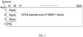
- FIG. 1 shows a frame structure suitable to this CBR mapping.
- each OPUk frame includes: a 6-byte Cbyte, where the Cbyte indicates the number of bytes of the mapped client signal; an OPUk payload area composed of (4*3808+1) bytes, for storing client signals; and a 1-byte Payload Structure Identifier (PSI).
- PSI Payload Structure Identifier
- the inventor finds that the existing agnostic CBR mapping method uses the fixed frame structure in FIG. 1 to map the client signals.
- the rate of the client signal is lower than the nominal value of the OPUk
- the positions not stuffed with client signals in the OPUk need to be stuffed with invalid bytes in order to meet the requirements of CBR transmission in the OTN system, thus leading to low bandwidth utilization ratio of the transmission channel.
- the OPUk needs to be stuffed with many invalid bytes, thus reducing the bandwidth utilization ratio of the transmission channel drastically.
- the definition of the OPUk TS structure in the existing G.709 is limited to the multiplexing from the ODUj to the ODUk, and the existing G.709 defines only 4 OPUk TSs or 16 OPUk TSs as regards the TS allocation. Moreover, the existing G.709 defines only the mapping path of the SDH service as regards the mapping of the CBR service.
- a first network element includes a frame generator which creates a frame with a fixed stuff area that includes a first set of bits for channel identification information, a second set of bits that provide justification information and a thirs set of bits that indicate either or both of payload type information and client signal fail information.
- the network further includes an output arrangement for placing the frame within a container for transport through the optical transport network.
- EP 1 826 926 A1 discloses a method for transmitting low rate signals over an optical transport network, including: adapting the low rate signals into low rate optical channel data units of the same rate level with the low rate signals; asynchronously mapping each of the low rate optical channel data units into a low rate optical channel data tributary unit respectively, and generating justification overhead used for rate adaptation for each of the low rate optical channel data units; and forming a higher order optical channel data unit with at least one low rate optical channel data tributary unit and justification overhead corresponding to the low rate optical channel data tributary unit.
- the embodiments of the present invention provide a method for transmitting client signals in an OTN according to claim 1, a transmitting device according to claim 7, a receiving method according to claim 11 and a receiving device according to claim 14.
- client signals are obtained, and the OPUk TS in the OPUk is determined according to the client signals; the client signals are mapped onto the OPUk TS in an agnostic CBR mapping mode; an overhead is added into the OPUk, and the OPUk with the added overhead is sent to the OTN. Therefore, the OPUk TSs of the OPUk may be occupied flexibly according to the rate of different client signals, a transmission channel suitable for the rate of each client signal is set up, the utilization ratio of the transmission channel is improved in the transparent agnostic CBR transmission process, and the OTN devices are more flexibly agnostic to the access services.
- the OPUk TSs are grouped and allocated according to the rate of different client signals on the basis of the OPUk frame structure to improve efficiency and flexibility of transmitting various client signals, and the agnostic CBR mapping mode in the ITU-T SG15 G.709 living list is applied to implement transparent CBR transmission for various client signals of different rates.
- the step of determining the OPUk TS in the OPUk according to the client signals specifically includes:
- This step may further include:
- This step may further include: grouping the determined OPUk TSs of the OPUk, and letting the OPUk TSs in the same group constitute a channel for transmitting client signals.
- the step of mapping the client signals to the OPUk TS in the OPUk in an agnostic CBR mapping mode includes:
- the step of mapping the client signals to the OPUk TS in the OPUk in an agnostic CBR mapping mode includes:
- the method may further include: adding a control identifier into the overhead added in the OPUk for at least one of the following purposes: identifying the OPUk TS corresponding to each client signal, identifying the number of OPUk TSs in the OPUk, identifying the type of the client signals mapped in the OPUk TS, and identifying the mode of mapping the client signal to the OPUk TS.
- the frame structure under the present invention is an improved frame structure based on the OPUk, and is called Optical Channel Payload Unit-k Agnostic tributary slot n (OPUk aTS-n), which refers to grouping into n agnostic TSs of the OPUk.
- OPUk aTS-n Optical Channel Payload Unit-k Agnostic tributary slot n
- FIG. 2 shows an OPUk aTS-n frame structure according to the first embodiment of the present invention. The improvement made by the present invention to the existing frame structure is described below with reference to FIG. 2 .
- FIG. 2 shows 6 OTN frames, which include 3808 columns numbered 17-3824. Each OTN frame includes four rows. Therefore, the OPUk payload area includes a total of 4 ⁇ 3808 bytes. As shown in FIG. 2 , the OPUk frame in this embodiment is divided into 4 OPUk TSs (namely, the value of n is 4) to constitute an OPUk aTS-4 frame structure.
- each OPUk TS of an OTN frame is available for transmitting 3808 bytes, and each OPUk TS needs to pass through 4 OTN frames in order to complete transmission of (3808 ⁇ 4) bytes.
- n (number) of OPUk TSs in the OPUk payload area depends on the rate of the client signal and the type and number of client signals so that each OPUk TS can use the agnostic CBR service mapping method to transmit each client signal transparently, and the maximum possible frequency offset of the client signals is tolerable. If it is impossible to divide the 3808 columns of the OPUk payload area into n OPUk TSs, certain columns in the OPUk payload area are stuffed fixedly. The number of columns to be stuffed is mod(3808/n).
- FIG. 3 shows an OPUk aTS-11 frame structure according to the second embodiment of the present invention.
- the last two columns (column 3823 and column 3824) in the OPUk payload area are stuffed with invalid data in this embodiment.
- the remaining 3806 bytes enable the 11 OPUk TSs to complete 346 cycles.
- FIG. 3 shows a method of stuffing column 3823 and column 3824 in the OPUk payload area.
- the fixedly stuffed column in the OPUk payload area is placed at the end of the OPUk frame uniformly to facilitate identification.
- the embodiments of the present invention do not restrict the position of the fixedly stuffed column.
- the embodiments of the present invention use reserved byte addition identifiers to indicate grouping of the OPUk TSs of the OPUk payload area, including: payload type identifier, multi-frame identifier, identifier of the type of the client signal, and OPUk TS group identifier.
- the identifiers employed herein are introduced below.
- the frame structure defined herein is identified by a PSI[0] byte (namely, Payload Type (PT) byte) defined in the existing OTN frame structure.
- PSI[0] is set as a value which is idle in the prior art, and this value is used herein to indicate an agnostic OPUk frame structure composed of n OPUk TSs (briefly known as OPUk aTS-n).
- the embodiments of the present invention use the reserved overhead byte in the OPUk overhead (OH) to set the value of the PSI[1] (as shown in FIG. 3 , the PSI occupies a byte in row 4 and column 15 of the frame).
- the PSI[1] value is adapted to indicate the number (n) of the OPUk TSs in the OPUk payload area.
- a multi-frame indication method is used to indicate the OPUk TS corresponding to 3 Cbyte's of the current frame. Therefore, a multi-frame cycle identifier identical to the number of OPUk TSs is required.
- the byte in column 16 and row 4 may be used as an indication.
- this byte is named as tributary slot MultiFrame Indicator (MFI-TS) of the OPUk TS.
- MFI-TS tributary slot MultiFrame Indicator
- the MFI-TS byte increases by 1 for every frame until its number is the same as the number of the TSs in the OPUk (namely, its number is the same as the value of the PSI[1] byte), whereupon the counter is reset and the count starts over.
- the 3 Cbyte's in this frame correspond to the first OPUk TSTS1; when the value of the MFI-TS byte indicates the second frame (the frame corresponding to 01 in FIG. 2 ), the 3 Cbyte's in this frame correspond to the second OPUk TSTS2, and so on.
- the Cbyte is adapted to hold the number of bytes (Cn) of the client signals stuffed in the OPUk payload area.
- the PSI[2m] byte indicates the type of the client signal mapped in the mOPUk TS, and the PSI[2m+1] indicates the group of the mOPUk TS.
- PSI[4] and PSI[5] indicate TS2
- PSI[6] and PSI[7] indicate TS3.
- Table 1 shows the relation between the PSI[2m] value and the type of the client signals mapped to the OPUk TS. Obviously, the relation between the value of the PSI[2m] and the type of the client signals may be set flexibly according to the service requirements, and such setting does not affect the essence of the present invention.
- each OPUk TS transmits independent client signals respectively, each OPUk TS corresponds to a different PSI [2m+1] value, indicating that the OPUk TS is in a different group. If some OPUk TSs are bundled into a greater transmission channel for transmitting client signals, the same value is configured for the PSI [2m+1] byte of the bundled OPUk TS, indicating that such OPUk TSs are in the same group.
- Table 2 shows an OPU4 which includes 11 unbundled OPUk TSs (OPUk aTS-11), and Table 2 shows an OPU4 which includes 11 OPUk TSs, of which the 4 th - 7 th OPUk TSs are bundled for transmitting ODU3 signals.
- the PSI[8], PSI[10], PSI[12], and PSI[14] are of the same value "33", indicating that the type of the client signals is ODU3.
- the PSI[7], PSI[9], PSI[11], and PSI[13] are of the same value "4", indicating that the corresponding 4 th -7 th OPUk TSs belong to the same group numbered "4".
- Table 4 shows definition of the PSI byte.
- the OPUk aTS-n frame structure constructed according to the method introduced above is suitable for most types of client signals, especially, the signals of the Ethernet, FC, and ESCON services.
- Table 5 is a list of mapping relations between most services and the OPUk aTS-n rate.
- the OPUk TS mapping relations listed in Table 5 are relatively reasonable, and accomplish a high line utilization ratio.
- Such an OPUk aTS-n frame structure supports grouping of 2-127 OPUk TSs.
- Table 5 takes OPU1-OPU4 as an example.
- Table 5 Number of OPUk TSs OPUk TS number of bytes Fixedly stuffed column OPU1 OPUk TS rate (Gbps) Client signal type suitable for transmission OPU2 OPUk TS rate (Gbps) Client signal type for transmission OPU3 OPUk TS rate (Gbps) Client signal type for transmission OPU4 OPUk TS rate (Gbps) Client signal type for transmission 2 1904 0 1.24416 FC1G 4.99764 FC4G 20.07526 -- 60.74053 -- 3 1269 1 0.82922 -- 3.33088 -- 13.37999 10GE LAN FC10G 40.48305 STM-256 ODU3 4 952 0 0.62208 FC0.45 2.49882 FC2G STM-16 10.03763 FC8G STM-64 30.37027 100GE-4L 5 761 3 0.49727 - 1.99748 - 8.02378 - 24.27707 100GE-5L 7 544 0 0.35547 - 1.42790 GE 5.73579 - 17.
- the OPUk TS rate unit is Gbps
- the OPUk TS rate is accurate to five decimal places
- the OPU4 rate in this embodiment is supposed to be 121.48106 Gbps.
- the foregoing embodiment describes the OPUk aTS-n and the grouping of the OPUk TSs. With respect to the specific implementation approaches, the foregoing embodiment has many variations.
- the PSI[0] value is 13 it indicates use of the OPUk aTS-n frame structure. In practice, however, the PSI[0] value is not necessarily 13. Those skilled in the art may use a value available in the prior art as the PSI[0] value for indicating use of the OPUk aTS-n frame structure.
- the value in the PSI[1] position is used to identify the number of grouped OPUk TSs.
- those skilled in the art may use another reserved field in the prior art to identify the number of grouped OPUk TSs.
- the PSI[2m] identifies the type of the client signals
- the PSI[2m+1] identifies the OPUk TS group mapped in the same OPUk TS.
- those skilled in the art may use another reserved field in the prior art to identify the type of the client signals and the OPUk TS group, and may define the mapping relation between the field value and the type of the client signals, and/or the value of each field, and the method of identifying the OPUk TS group as required. Such variations do not affect the implementation of the present invention.
- the OPUk aTS-n frame structure is introduced above, and the following describes how to map the client signal to the frame of this structure, and transmit the client signal.
- the client signal Before the client signal is mapped to the OPUk aTS-n frame structure, it is necessary to define the corresponding nOPUk TS agnostic to the k(ODTUan-k) frame structure according to the OPUk aTS-n frame structure, and the rate of the ODTUan-k frame structure is the same as the rate of the OPUk.
- the ODTUan-k frame unit is a structure composed of 4n rows and int(3808/n) columns. Moreover, 3 Cbyte spaces exist at the head of the structure, and each Cbyte space occupies 2 bytes, as shown in FIG. 4 . Therefore, a Cbyte space that occupies two bytes can indicate a total of 65535 bytes, and an ODTUan-k unit has a total of 4n ⁇ int(3808/n) ⁇ 15232 bytes. Therefore, the Cbyte space that occupies two bytes is fully capable of indicating the payload bytes of the ODTUan-k frame.
- this embodiment may bundle some OPUk TSs in the OPUk aTS-n frame structure to form a greater transmission channel for transmitting client signals of higher rates, thus fulfilling the requirements of transmitting different service types to the utmost.
- FIG. 5 shows how to bundle 4 of 11 OPUk TSs into 4 ⁇ ODTUa11-k when the number of OPUk TSs of an OPUk is 11.
- the 4 ⁇ ODTUa11-4 frame structure composed of 4 OPUk TSs has 3 Cbyte spaces, and each Cbyte space has 8 bytes, which are sufficient for indicating 1384 ⁇ 44 bytes.
- the following embodiment describes how to map multiple client signals to the OTN frame provided herein transparently at a full rate through the agnostic CBR mapping method specified in the ITU-T SG15 G.709 living list.
- the OPU4 is divided into 11 OPUk TSs.
- the first 10 OPUk TSs are used to transmit 10GE LAN signals, and the 11 th OPUk TS is used to transmit ODU2 signals.
- the transmitter receives ten 10GE LAN signals and one ODU2 signal respectively, extracts the clocks of the signals, and compares the clocks with the local clocks to determine the Cn value of the signals.
- the transmitter maps the Cn value of each signal to the Cbyte space of the current ODTUa11-4 frame.
- the transmitter maps the Cn bytes of each signal to the payload area of each ODTUa11-4 frame structure respectively based on the ⁇ - algorithm rule put forward in the agnostic CBR mapping method in the ITU-T SG15 G.709 living list. As shown in FIG.
- the transmitter maps the Cn value determined in the received ODU2 signal to the Cbyte space; at the n th ODTUa11-4 frame, the transmitter maps the ODU2 signal of Cn bytes to the payload area of the ODTUa11-4 frame (346 ⁇ 44) according to the Cn value of the Cbyte space of the previous frame.
- the byte rate of the ODTUa11-4 frame structure is the same as the byte rate of the OPU4 frame, and the client signal clock is asynchronous to the clock of the ODTUa11-4 frame.
- the Cn value is adjusted to compensate for the deviation between the asynchronous clocks.
- the transmitter constructs an OPU4 aTS-11 frame structure, and maps each byte of the ODTUa11-4 frame structure (which is already mapped to the client signal) to each byte of the OPUk TS corresponding to the OPU4 aTS-11 frame structure.
- an OPU4 frame divided into 11 OPUk TSs can carry 11 ODTUa11-4 frame structures, of which 10 ODTUa11-4 frames are mapped to 10GE LAN client signals and one ODTUa11-4 frame is mapped to the ODU2 signal.
- the transmitter adds the overhead such as PSI byte and MFI-TS byte into the OPU4 aTS-11 frame to form an OTU4 line frame, which is sent to the OTN.
- a method for receiving client signals in an OTN includes:
- the method for resolving the OPUk TS of the OPUk in the agnostic CBR mapping mode to obtain the client signals includes:
- the receiver identifies the agnostic mapping mode of multiple OPUk TSs according to the PSI[0] byte in the OPU4, identifies the OPU4 aTS-11 frame according to the PSI[1] byte, identifies the mapped type of the client signals according to the value of the PSI[2m], identifies the unbundled OPUk TS according to the value of the PSI[2m+1], resolves the OPU4 aTS-11 into ODTUa11-4 frames according to the multi-frame number of the MFI-TS, resolves the ODTUa11-4 frame into the Cn value of each client signal, recovers the clock of 11 client signals according to the Cn value, and recovers data flows of ten 10GE LAN signals and one ODU2 signal.
- the bundled OPUk TS corresponds to the 4 ⁇ ODTUa11-4 structure as shown in FIG. 5 . Therefore, on the occasion of mapping the 4 ⁇ ODTUa11-4 frame structure byte to the 4 bundled OPUk TSs of the OPU4 aTS-11, the Cbyte space is split into 12 Cbyte spaces as indicated by the dotted line in FIG. 5 or based on other rules. In this way, the payload area is split into 4 parts, which are mapped to the 4 bundled OPUk TSs of the OPU4 aTS-11 respectively.
- the program may be stored in a computer-readable storage medium.
- the storage medium may be a Read-Only Memory (ROM)/Random Access Memory (RAM), magnetic disk, or Compact Disk (CD).
- ROM Read-Only Memory
- RAM Random Access Memory
- CD Compact Disk
- a further step is: stuffing the corresponding fixed byte positions in each row of the OPUk payload area with invalid data so that the number of non-stuffed bytes in each row of the OPUk payload area is an integer multiple of the number (n) of the OPUk TSs.
- a further step is:
- the program may further perform this step: adding a control identifier into the overhead for at least one of the following purposes: identifying the OPUk TS corresponding to each client signal, identifying the number of OPUk TSs in the OPUk, identifying the type of the client signals mapped in the OPUk TS.
- the method further includes: using a control identifier added into the overhead to identify the mapping from the client signal to the OPUk TS.
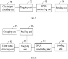
- a device for transmitting client signals in an OTN in the first embodiment of the present invention includes:
- the mapping unit 72 may map some client signals to the OPUk TSs of some OPUk's in an agnostic CBR mapping mode, and map the remaining client signals to the OPUk TSs of the remaining OPUk's in a GFP mapping mode or ATM cell mapping mode.
- mapping unit 72 If the mapping unit 72 employs the agnostic CBR mapping mode, the mapping unit 72 needs to:
- FIG. 8 shows a device for transmitting client signals in an OTN in the second embodiment of the present invention.
- the client signal obtaining unit 81, mapping unit 82, OPUk constructing unit 83, and sending unit 84 are the same as those in the foregoing embodiment.
- the grouping unit 85 is adapted to determine the number (n) of OPUk TSs in the OPUk payload area, where each OPUk TS occupies the OPUk payload area bytes by using the number (n) of the OPUk TSs as a cycle, and the number (n) of the OPUk TSs ranges from 2 to 127.
- the stuffing unit 86 is adapted to: stuff the corresponding fixed byte positions in each row of the OPUk payload area with invalid data according to the number (n) of the OPUk TS determined by the grouping unit so that the number of non-stuffed bytes in each row of the OPUk payload area is an integer multiple of the number (n) of the OPUk TSs.
- a device for transmitting client signals in an OTN is provided in an embodiment of the present invention. As shown in FIG. 9 , the device includes:
- the presetting unit 92 includes:
- the presetting unit 92 includes at least one of the following units:
- the mapping unit 93 may include:
- the mapping unit includes a hybrid mapping unit, adapted to:
- the device further includes an OPUk constructing unit 96, adapted to: add a control identifier into the overhead added in the OPUk for at least one of the following purposes: identifying the OPUk TS corresponding to each client signal, identifying the number of OPUk TSs in the OPUk payload area, identifying the type of the client signals mapped in the OPUk TS, and identifying the mode of mapping the client signal to the OPUk TS.
- an OPUk constructing unit 96 adapted to: add a control identifier into the overhead added in the OPUk for at least one of the following purposes: identifying the OPUk TS corresponding to each client signal, identifying the number of OPUk TSs in the OPUk payload area, identifying the type of the client signals mapped in the OPUk TS, and identifying the mode of mapping the client signal to the OPUk TS.
- a device for receiving client signals in an OTN is provided in an embodiment of the present invention. As shown in FIG. 10 , the device includes:
- the receiving unit 101 is adapted to receive an OPUk, which may be included in an ODUk.
- the first resolving unit 102 is adapted to resolve out an ODTUan-k, and more specifically, extract the number of OPUk TSs (n) indicated in the OPUk overhead byte, construct an ODTUan-k frame structure composed of 4n ⁇ int(3808/n) bytes, and resolve out an ODTUan-k according to the mapping relation between the number of bytes of the client signal indicated in the overhead byte of the OPUk and the OPUk TS.
- the first resolving unit extracts the number of OPUk TSs (n) indicated in the OPUk overhead byte, and constructs an ODTUan-k frame structure composed of 4n ⁇ int(3808/n)x bytes in light of the OPUk TS group identifier indicated in the OPUk overhead byte, where x represents the number of OPUk TSs with the same group identifier.
- the second resolving unit 103 includes:
- the second resolving unit 103 recovers the client signal clock according to the number of the bytes of the client signal in the ODTUan-k overhead, and recovers the client signal data flow according to the client signals mapped in the ODTUan-k payload area and the type of the client signals indicated in the OPUk overhead byte.
- the OPUk TSs are grouped and allocated according to the rate of different client signals on the basis of the OPUk frame structure to improve efficiency and flexibility of transmitting various client signals, and the agnostic CBR mapping mode in the ITU-T SG15 G.709 living list is applied to implement transparent agnostic CBR transmission for various client signals of different rates. Therefore, it is not necessary to define a fixed mapping mode for each client signal of a different rate.
- the embodiments of the present invention enables effective access of various existing client signals, and are highly agnostic to the client signals of new rates that will come forth in the future, make the OTN standard system more agnostic to the client signals, make the OTN device more flexibly agnostic to the accessing client signals, and improve the bandwidth utilization ratio of the line.
- each OPUk TS can use an agnostic CBR mapping method, or use a GFP or ATM cell mapping method already defined in the G.709, or combination thereof.
- the PSI[2m] may be further defined so that it indicates both the service type and the mapping mode, as shown in Table 7.
- FIG. 11 shows a structure of an ODTUn-k frame that employs a GFP or ATM cell mapping mode. The position that previously holds a Cbyte now holds a fix stuff byte.
- the data packet On the occasion of mapping a data packet to an ODTUn-k in a GFP mode, the data packet is encapsulated into a GFP frame based on the G.7041, and then each byte of the GFP frame is put into an ODTUn-k structure. The clock deviation between the GFP frame and the ODTUn-k is corrected through idle frames.
- the ATM cell mapping method is similar to the GFP frame mapping method except no need of encapsulating the ATM cell into a GFP frame.
- the method of mapping from an ODTUn-k to an OPUk in a GFP or ATM mapping mode is the same as the method of mapping from an ODTUan-k to an OPUk in agnostic CBR mapping mode.
- the position that previously holds the Cbyte corresponding to the OPUk TS based on a GFP or ATM mapping method now holds a fix stuff byte.
- the TS2 employs a GFP mapping mode, and other TSs employ an agnostic CBR mapping mode.
Landscapes
- Engineering & Computer Science (AREA)
- Computer Networks & Wireless Communication (AREA)
- Signal Processing (AREA)
- Time-Division Multiplex Systems (AREA)
- Communication Control (AREA)
- Manufacture, Treatment Of Glass Fibers (AREA)
- Data Exchanges In Wide-Area Networks (AREA)
- Small-Scale Networks (AREA)
Claims (15)
- Procédé d'émission de signaux clients dans un Réseau de Transport Optique, OTN, comprenant :l'obtention des signaux clients ;la mise en correspondance des signaux clients dans des Créneaux Tributaires d'Unité k de Charge Utile de Canal Optique, TS OPUk, d'une trame OPUk, la trame OPUk comprenant un surdébit ;l'envoi de la trame OPUk avec le surdébit ajouté à l'OTN ;la mise en correspondance des signaux clients dans les TS OPUk de la trame OPUk comprenant :la mise en correspondance d'un premier signal client parmi les signaux clients dans les TS OPUk correspondant au premier signal client dans un mode de mise en correspondance CBR agnostique ; etla mise en correspondance d'un second signal client parmi les signaux clients dans les TS OPUk correspondant au second signal client dans un mode de mise en correspondance GFP ou un mode de mise en correspondance de cellule ATM ;l'étape de mise en correspondance du premier signal client parmi les signaux clients dans les TS OPUK correspondant au premier signal client dans le mode de mise en correspondance CBR agnostique comprenant :la mise en correspondance d'une valeur qui indique le nombre d'octets avec un surdébit d'une trame d'Unité Tributaire de Données de Canal Optique, ODTU, en cours, la valeur qui indique le nombre d'octets étant déterminée par comparaison d'une horloge du premier signal client avec une horloge locale et indiquant le nombre d'octets à insérer dans une zone de charge utile d'une trame ODTU faisant suite à la trame ODTU en cours ;la mise en correspondance d'octets du premier signal client avec la zone de charge utile de la trame ODTU faisant suite à la trame ODTU en cours en fonction de la valeur qui indique le nombre d'octets dans le surdébit de la trame ODTU en cours ;la mise en correspondance d'octets de chaque trame ODTU avec au moins un TS OPUk.
- Procédé selon la revendication 1, un débit d'octets de trame ODTU étant le même qu'un débit d'octets de la trame OPUk, l'horloge du premier signal client étant asynchrone par rapport à une horloge de la trame ODTU, et la valeur qui indique le nombre d'octets étant ajustée pour compenser un écart entre l'horloge du premier signal client et l'horloge de la trame ODTU.
- Procédé selon la revendication 2, le surdébit ajouté comprenant un octet Indicateur de Multitrames de créneaux tributaires, MFI-TS, qui augmente de 1 pour chaque trame jusqu'à ce que son nombre soit le même que le nombre du TS OPUk dans la trame OPUk.
- Procédé selon l'une quelconque des revendications 1 à 3, la trame OPUk comprenant une zone de charge utile OPUk qui comprend un total de 4 rangées et 3808 colonnes ; les 3808 colonnes de la zone de charge utile OPUk étant divisées en n TS OPUk, n indiquant le nombre de TS OPUk.
- Procédé selon la revendication 4, certaines colonnes dans la zone de charge utile OPUk étant remplies de manière fixe, le nombre de colonnes à remplir étant mod (3808/n).
- Procédé selon la revendication 4 ou 5, chaque trame ODTU comprenant une zone de charge utile qui est constituée de 4n rangées et int(3808/n) colonnes.
- Dispositif d'émission de signaux clients dans un Réseau de Transport Optique, OTN, comprenant :une unité d'obtention de signaux clients (91), adaptée pour obtenir les signaux clients ; une unité de mise en correspondance (93), adaptée pour mettre en correspondance les signaux clients dans des Créneaux Tributaires d'Unité k de Charge utile de Canal Optique, TS OPUk, d'une trame OPUk, la trame OPUk comprenant un surdébit ; etune unité d'envoi (95), adaptée pour envoyer la trame OPUk avec le surdébit à l'OTN ; l'unité de mise en correspondance (93), adaptée pour mettre en correspondance les signaux clients dans les TS OPUk de la trame OPUk comprenant :la mise en correspondance d'un premier signal client parmi les signaux clients dans les TS OPUk correspondant au premier signal client dans un mode de mise en correspondance CBR agnostique ; etla mise en correspondance d'un second signal client parmi les signaux clients dans les TS OPUk correspondant au second signal client dans un mode de mise en correspondance GFP ou un mode de mise en correspondance de cellule ATM ;l'unité de mise en correspondance (93) étant adaptée pour mettre en correspondance le premier signal client dans les TS OPUk correspondant au premier signal client dans le mode de mise en correspondance CBR agnostique dans le processus suivant :la mise en correspondance d'une valeur qui indique le nombre d'octets dans un surdébit d'une trame d'Unité Tributaire de Données de Canal Optique, ODTU, en cours, la valeur qui indique le nombre d'octets étant déterminée par comparaison d'une horloge du premier signal client avec une horloge locale et indiquant le nombre d'octets à insérer dans une zone de charge utile d'une trame ODTU faisant suite à la trame ODTU en cours ;la mise en correspondance d'octets du premier signal client avec la zone de charge utile de la trame ODTU faisant suite à la trame ODTU en cours en fonction de la valeur qui indique le nombre d'octets dans le surdébit de la trame ODTU en cours ;la mise en correspondance d'octets de chaque trame ODTU avec au moins un TS OPUk.
- Dispositif selon la revendication 7, un débit d'octets de la trame ODTU étant le même qu'un débit d'octets de la trame OPUk, l'horloge du premier signal client étant asynchrone par rapport à une horloge de la trame ODTU, et la valeur qui indique le nombre d'octets étant ajustée pour compenser un écart entre l'horloge du premier signal client et l'horloge de la trame ODTU.
- Dispositif selon la revendication 8, le surdébit ajouté comprenant un octet Indicateur de Multitrames de créneaux tributaires, MFI-TS, qui augmente de 1 pour chaque trame jusqu'à ce que son nombre soit le même que le nombre des TS OPUk dans la trame OPUk.
- Dispositif selon la revendication 8 ou 9, la trame OPUk comprenant une zone de charge utile OPUk qui comprend un total de 4 rangées et 3808 colonnes ; les 3808 colonnes de la zone de charge utile OPUk étant divisées en n TS OPUk, n indiquant le nombre de TS OPUk ;
chaque trame ODTU comprenant une zone de charge utile qui est constituée de 4n rangées et int(3808/n) colonnes. - Procédé de réception de signaux clients dans un Réseau de Transport Optique, OTN, comprenant :la réception d'une trame d'Unité k de Charge Utile de Canal Optique, OPUk ;la résolution de la trame OPUk pour obtenir des TS OPUk dans une zone de charge utile OPUk de la trame OPUk ;la résolution des TS OPUk pour obtenir des signaux clients ;une première partie de TS OPUk étant mise en correspondance avec un premier signal client dans un Débit Binaire Constant, CBR, agnostique, une seconde partie de TS OPUk étant mise en correspondance avec un second signal client dans un mode de mise en correspondance GFP ou un mode de mise en correspondance de cellule ATM ; l'étape de résolution des TS OPUk pour obtenir le premier signal client comprenant :la résolution d'au moins un TS OPUk pour obtenir une trame d'Unité Tributaire de Données de Canal Optique, ODTU, chaque trame ODTU comprenant un surdébit et une zone de charge utile, un surdébit d'une trame ODTU en cours comprenant une valeur qui indique le nombre d'octets déterminé par comparaison d'horloges du premier signal client avec des horloges locales, et indique le nombre d'octets insérés dans une zone de charge utile d'une trame ODTU faisant suite à la trame ODTU en cours ;la résolution des trames ODTU pour obtenir les valeurs qui indiquent le nombre d'octets ;la récupération d'une horloge du premier signal client en fonction de la valeur qui indique le nombre d'octets ; etla récupération d'un flux de données de premier signal client.
- Procédé selon la revendication 11, un débit d'octets de la trame ODTU étant le même qu'un débit d'octets de la trame OPUk, l'horloge du premier signal client étant asynchrone par rapport à une horloge de la trame ODTU, et la valeur qui indique le nombre d'octets étant ajustée pour compenser un écart entre l'horloge du premier signal client et l'horloge de la trame ODTU.
- Procédé selon la revendication 11 ou 12, la zone de charge utile OPUk comprenant un total de 4 rangées et 3808 colonnes, les 3808 colonnes de la zone de charge utile OPUk étant divisées en n TS OPUk, n indiquant le nombre de TS OPUk ;
chaque trame ODTU comprenant une zone de charge utile qui est constituée de 4n rangées et int(3808/n) colonnes. - Dispositif de réception de signaux clients dans un Réseau de Transport Optique, OTN, comprenant :une unité de réception (101), adaptée pour recevoir une Unité k de Charge Utile de Canal Optique, OPUk, l'OPUk comprenant une zone de charge utile OPUk qui est divisée en n Créneaux Tributaires OPUk, TS OPUk, n indiquant le nombre de Créneaux Tributaires OPUk ;une première unité de résolution (102), adaptée pour résoudre l'OPUk afin d'obtenir les TS OPUk ;une seconde unité de résolution (103), adaptée pour résoudre les TS OPUk de la trame OPUk pour obtenir les signaux clients ; une première partie de TS OPUk étant mise en correspondance avec un premier signal client dans un Débit Binaire Constant, CBR, agnostique, une seconde partie de TS OPUk étant mise en correspondance avec un second signal client dans un mode de mise en correspondance GFP ou un mode de mise en correspondance de cellule ATM ;la seconde unité de résolution (103) comprenant :
une unité pour résoudre le nombre d'octets du premier signal client, adaptée pour :résoudre un surdébit du TS OPUk de l'OPUk pour obtenir une valeur Cn qui indique le nombre d'octets déterminé par comparaison d'horloges des premiers signaux clients avec des horloges locales et indique le nombre d'octets du premier signal client, et résoudre les informations d'horloge du premier signal client en fonction de la valeur Cn du premier signal client ; etune unité de résolution de signal client, adaptée pour supprimer la mise en correspondance du premier signal client dans le TS OPUk de l'OPUk en fonction d'une valeur Cn qui indique le nombre d'octets et les informations d'horloge du premier signal client, et récupérer le premier signal client. - Dispositif selon la revendication 14, la zone de charge utile OPUk comprenant un total de 4 rangées et 3808 colonnes ; les 3808 colonnes de la zone de charge utile OPUk étant divisées en n TS OPUk, n indiquant le nombre de TS OPUk ;
chaque trame ODTU comprenant une zone de charge utile qui est constituée de 4n rangées et int(3808/n) colonnes.
Priority Applications (1)
| Application Number | Priority Date | Filing Date | Title |
|---|---|---|---|
| EP22166695.1A EP4084367A1 (fr) | 2007-04-17 | 2008-04-16 | Procédé et dispositifs pour la transmission de signaux client dans un réseau de transport optique |
Applications Claiming Priority (6)
| Application Number | Priority Date | Filing Date | Title |
|---|---|---|---|
| CN200710090273XA CN101291179B (zh) | 2007-04-17 | 2007-04-17 | 一种光传送网中客户信号传送方法及相关设备 |
| EP14175177.6A EP2811673B1 (fr) | 2007-04-17 | 2008-04-16 | Procédé et dispositifs pour la transmission de signaux client dans un réseau de transport optique |
| EP16158592.2A EP3059888B1 (fr) | 2007-04-17 | 2008-04-16 | Procédé et dispositifs pour la transmission de signaux client dans un réseau de transport optique |
| EP11168964.2A EP2365652B1 (fr) | 2007-04-17 | 2008-04-16 | Procédé et dispositifs pour la transmission de signaux client dans un réseau de transport optique |
| EP08734076A EP2148476B1 (fr) | 2007-04-17 | 2008-04-16 | Procédé de transport d'un signal client dans le réseau de transport optique et équipement apparenté |
| PCT/CN2008/070718 WO2008125060A1 (fr) | 2007-04-17 | 2008-04-16 | Procédé de transport d'un signal client dans le réseau de transport optique et équipement apparenté |
Related Parent Applications (5)
| Application Number | Title | Priority Date | Filing Date |
|---|---|---|---|
| EP16158592.2A Division EP3059888B1 (fr) | 2007-04-17 | 2008-04-16 | Procédé et dispositifs pour la transmission de signaux client dans un réseau de transport optique |
| EP16158592.2A Division-Into EP3059888B1 (fr) | 2007-04-17 | 2008-04-16 | Procédé et dispositifs pour la transmission de signaux client dans un réseau de transport optique |
| EP08734076A Division EP2148476B1 (fr) | 2007-04-17 | 2008-04-16 | Procédé de transport d'un signal client dans le réseau de transport optique et équipement apparenté |
| EP14175177.6A Division EP2811673B1 (fr) | 2007-04-17 | 2008-04-16 | Procédé et dispositifs pour la transmission de signaux client dans un réseau de transport optique |
| EP11168964.2A Division EP2365652B1 (fr) | 2007-04-17 | 2008-04-16 | Procédé et dispositifs pour la transmission de signaux client dans un réseau de transport optique |
Related Child Applications (2)
| Application Number | Title | Priority Date | Filing Date |
|---|---|---|---|
| EP22166695.1A Division-Into EP4084367A1 (fr) | 2007-04-17 | 2008-04-16 | Procédé et dispositifs pour la transmission de signaux client dans un réseau de transport optique |
| EP22166695.1A Division EP4084367A1 (fr) | 2007-04-17 | 2008-04-16 | Procédé et dispositifs pour la transmission de signaux client dans un réseau de transport optique |
Publications (2)
| Publication Number | Publication Date |
|---|---|
| EP3570466A1 EP3570466A1 (fr) | 2019-11-20 |
| EP3570466B1 true EP3570466B1 (fr) | 2022-09-28 |
Family
ID=39863278
Family Applications (6)
| Application Number | Title | Priority Date | Filing Date |
|---|---|---|---|
| EP19170196.0A Active EP3570466B1 (fr) | 2007-04-17 | 2008-04-16 | Procédé et dispositifs pour la transmission de signaux client dans un réseau de transport optique |
| EP22166695.1A Pending EP4084367A1 (fr) | 2007-04-17 | 2008-04-16 | Procédé et dispositifs pour la transmission de signaux client dans un réseau de transport optique |
| EP08734076A Active EP2148476B1 (fr) | 2007-04-17 | 2008-04-16 | Procédé de transport d'un signal client dans le réseau de transport optique et équipement apparenté |
| EP11168964.2A Active EP2365652B1 (fr) | 2007-04-17 | 2008-04-16 | Procédé et dispositifs pour la transmission de signaux client dans un réseau de transport optique |
| EP14175177.6A Active EP2811673B1 (fr) | 2007-04-17 | 2008-04-16 | Procédé et dispositifs pour la transmission de signaux client dans un réseau de transport optique |
| EP16158592.2A Active EP3059888B1 (fr) | 2007-04-17 | 2008-04-16 | Procédé et dispositifs pour la transmission de signaux client dans un réseau de transport optique |
Family Applications After (5)
| Application Number | Title | Priority Date | Filing Date |
|---|---|---|---|
| EP22166695.1A Pending EP4084367A1 (fr) | 2007-04-17 | 2008-04-16 | Procédé et dispositifs pour la transmission de signaux client dans un réseau de transport optique |
| EP08734076A Active EP2148476B1 (fr) | 2007-04-17 | 2008-04-16 | Procédé de transport d'un signal client dans le réseau de transport optique et équipement apparenté |
| EP11168964.2A Active EP2365652B1 (fr) | 2007-04-17 | 2008-04-16 | Procédé et dispositifs pour la transmission de signaux client dans un réseau de transport optique |
| EP14175177.6A Active EP2811673B1 (fr) | 2007-04-17 | 2008-04-16 | Procédé et dispositifs pour la transmission de signaux client dans un réseau de transport optique |
| EP16158592.2A Active EP3059888B1 (fr) | 2007-04-17 | 2008-04-16 | Procédé et dispositifs pour la transmission de signaux client dans un réseau de transport optique |
Country Status (10)
| Country | Link |
|---|---|
| US (6) | US20100067905A1 (fr) |
| EP (6) | EP3570466B1 (fr) |
| CN (1) | CN101291179B (fr) |
| AT (1) | ATE512516T1 (fr) |
| DK (1) | DK2148476T3 (fr) |
| ES (4) | ES2365964T3 (fr) |
| PL (1) | PL2148476T3 (fr) |
| PT (1) | PT2148476E (fr) |
| RU (1) | RU2421925C1 (fr) |
| WO (1) | WO2008125060A1 (fr) |
Families Citing this family (42)
| Publication number | Priority date | Publication date | Assignee | Title |
|---|---|---|---|---|
| CN101291179B (zh) | 2007-04-17 | 2011-03-23 | 华为技术有限公司 | 一种光传送网中客户信号传送方法及相关设备 |
| CN101729937B (zh) * | 2008-10-27 | 2015-01-28 | 中兴通讯股份有限公司 | 物理层操作管理维护消息传输方法及装置 |
| CN101729370B (zh) * | 2008-10-31 | 2011-09-14 | 华为技术有限公司 | 调节业务占用带宽的方法、装置和系统 |
| CN106130683B (zh) * | 2009-02-10 | 2020-01-10 | 华为技术有限公司 | 客户信号映射和解映射的实现方法及装置 |
| US8359525B2 (en) * | 2009-03-06 | 2013-01-22 | Electronics And Telecommunications Research Institute | Method and apparatus for transmitting data in optical transport network |
| CN101834688B (zh) | 2009-03-09 | 2011-08-31 | 华为技术有限公司 | 光传送网中的映射、解映射方法及装置 |
| JP5251620B2 (ja) * | 2009-03-09 | 2013-07-31 | 富士通株式会社 | フレーム生成装置およびフレーム生成方法 |
| CN101854220A (zh) * | 2009-04-01 | 2010-10-06 | 华为技术有限公司 | 一种业务数据发送、接收的方法和装置 |
| CN103973265B (zh) * | 2009-06-09 | 2017-01-18 | 华为技术有限公司 | 一种ODUflex通道带宽的无损调整方法和光传送网 |
| ES2414634T3 (es) | 2009-06-09 | 2013-07-22 | Huawei Technologies Co., Ltd. | Método de ajuste sin pérdida de un ancho de banda de un canal ODUflex y el canal ODUflex |
| CN102014312B (zh) * | 2009-09-04 | 2014-03-12 | 中兴通讯股份有限公司 | 客户信号失效的指示方法与装置 |
| CN101692633B (zh) * | 2009-09-10 | 2012-12-19 | 中兴通讯股份有限公司 | 一种编码/解码的方法及装置 |
| EP3094022B1 (fr) * | 2009-09-17 | 2018-07-04 | Huawei Technologies Co., Ltd. | Redimensionnement sans à-coup dynamique dans des réseaux de transport optique |
| JP5540675B2 (ja) * | 2009-12-07 | 2014-07-02 | 富士通株式会社 | 伝送装置および信号収容方法 |
| JP2011146917A (ja) * | 2010-01-14 | 2011-07-28 | Fujitsu Ltd | インタフェース装置、分離方法、多重化方法 |
| CN102196321A (zh) * | 2010-03-05 | 2011-09-21 | 华为技术有限公司 | 100ge数据在光传送网中的传送方法和数据发送装置 |
| WO2011148472A1 (fr) * | 2010-05-26 | 2011-12-01 | 富士通株式会社 | Dispositif de transmission d'un réseau de transport optique et son procédé de contrôle de bourrage |
| WO2012028185A1 (fr) * | 2010-09-02 | 2012-03-08 | Telefonaktiebolaget L M Ericsson (Publ) | Procédé de transmission de trafic dans réseau de communication et appareil de réseau de communication |
| CN102014316B (zh) * | 2010-10-12 | 2013-09-11 | 华为技术有限公司 | 数据处理方法和装置 |
| JP5640719B2 (ja) * | 2010-12-15 | 2014-12-17 | 日本電気株式会社 | 光伝送システム、送信器、受信器及び制御方法 |
| JP5796327B2 (ja) * | 2011-04-07 | 2015-10-21 | 富士通株式会社 | 光伝送装置及び光伝送方法 |
| US8494363B2 (en) * | 2011-04-21 | 2013-07-23 | Cortina Systems, Inc. | Signal format conversion apparatus and methods |
| CN102170599A (zh) * | 2011-05-09 | 2011-08-31 | 中兴通讯股份有限公司 | 实现业务映射的方法及装置 |
| CN102281477B (zh) * | 2011-08-18 | 2018-02-16 | 中兴通讯股份有限公司 | 一种实现otn业务映射及解映射的方法和装置 |
| US8934479B2 (en) * | 2011-10-28 | 2015-01-13 | Infinera Corporation | Super optical channel transport unit signal supported by multiple wavelengths |
| KR20130116415A (ko) * | 2012-03-14 | 2013-10-24 | 한국전자통신연구원 | 광 전달망에서의 보호 절체 방법 및 장치 |
| CN102884808B (zh) * | 2012-06-19 | 2015-11-25 | 华为技术有限公司 | 一种分配光频谱带宽资源的方法及装置 |
| CN103795605B (zh) * | 2014-01-14 | 2017-01-11 | 烽火通信科技股份有限公司 | 将otn信号转换为以太网净荷的方法及系统 |
| US10079641B1 (en) * | 2014-04-01 | 2018-09-18 | Sprint Spectrum, L.P. | Systems and methods of transporting data over an optical transport network |
| KR101819269B1 (ko) * | 2014-06-27 | 2018-02-28 | 한국전자통신연구원 | 다계층 통합 패브릭 스위치 기반의 패킷-회선 통합 전송 시스템에서 otn 트래픽 관리 장치 및 방법 |
| CN105871467B (zh) * | 2015-01-19 | 2018-03-23 | 中国移动通信集团公司 | 一种光网络系统及光网络系统中的自适应连接的装置 |
| KR102328071B1 (ko) | 2015-02-04 | 2021-11-18 | 한국전자통신연구원 | 광전송망의 트래픽을 처리하는 방법 및 장치 |
| EP3065318B1 (fr) * | 2015-03-06 | 2020-04-22 | Alcatel Lucent | Procédé de transmission |
| CN106559141B (zh) | 2015-09-25 | 2020-01-10 | 华为技术有限公司 | 一种信号发送、接收方法、装置及系统 |
| CN106941388B (zh) * | 2016-01-04 | 2019-11-29 | 南京中兴软件有限责任公司 | 通道状态的确定方法及装置 |
| US10298348B2 (en) * | 2016-04-01 | 2019-05-21 | Ipg Photonics Corporation | Transparent clocking in a cross connect system |
| RU2691748C1 (ru) | 2016-05-27 | 2019-06-18 | Хуавей Текнолоджиз Ко., Лтд. | Способ передачи услуги и первое передающее устройство |
| JP6636653B2 (ja) | 2016-07-22 | 2020-01-29 | 華為技術有限公司Huawei Technologies Co.,Ltd. | マルチサービス伝送及び受信方法並びに装置 |
| CN109981209B (zh) * | 2017-12-28 | 2022-01-28 | 中兴通讯股份有限公司 | 光传送网中业务发送、接收方法及装置 |
| WO2019153253A1 (fr) * | 2018-02-09 | 2019-08-15 | 华为技术有限公司 | Procédé et dispositif de traitement de données de service dans un réseau de transport optique |
| US10979209B1 (en) * | 2018-10-08 | 2021-04-13 | Acacia Communications, Inc. | System, method, and apparatus for mapping synchronous and asynchronous data |
| CN115515033A (zh) * | 2019-09-30 | 2022-12-23 | 华为技术有限公司 | 一种光传送网中的业务处理的方法、装置和系统 |
Family Cites Families (16)
| Publication number | Priority date | Publication date | Assignee | Title |
|---|---|---|---|---|
| US20040013129A1 (en) * | 2001-08-07 | 2004-01-22 | Xiaojun Fang | Method and protocol for packetized optical channel based on digital wrapper |
| US20030048813A1 (en) * | 2001-09-05 | 2003-03-13 | Optix Networks Inc. | Method for mapping and multiplexing constant bit rate signals into an optical transport network frame |
| US7286487B2 (en) * | 2002-11-18 | 2007-10-23 | Infinera Corporation | Optical transmission network with asynchronous mapping and demapping and digital wrapper frame for the same |
| US7787460B2 (en) | 2003-10-08 | 2010-08-31 | Ciena Corporation | System and method for switching packet traffic over an optical transport network |
| CA2571262C (fr) * | 2004-06-16 | 2015-08-11 | Infinera Corporation | Architecture de cadrage numerique universelle pour le transport de signaux clients de toute charge utile client et tout type de format |
| CN100349390C (zh) * | 2004-08-11 | 2007-11-14 | 华为技术有限公司 | 光传送网中传输低速率业务信号的方法及其装置 |
| CN1744470A (zh) | 2004-09-02 | 2006-03-08 | 华为技术有限公司 | 光网络承载异步传输模式业务的方法及装置 |
| CN100590997C (zh) * | 2004-11-02 | 2010-02-17 | 华为技术有限公司 | 一种otn网络中业务复用的开销处理方法 |
| ES2340162T3 (es) * | 2004-11-12 | 2010-05-31 | Alcatel Lucent | Metodo y aparato para transportar una señal de capa de cliente sobre una red de transporte optico (otn). |
| CN100373847C (zh) * | 2004-12-14 | 2008-03-05 | 华为技术有限公司 | 在光传送网中传输低速率业务信号的方法 |
| CN1791057B (zh) * | 2004-12-15 | 2011-06-15 | 华为技术有限公司 | 在光传送网中传输数据业务的方法及其装置 |
| RU2289207C1 (ru) | 2005-05-13 | 2006-12-10 | Закрытое акционерное общество ЦНИТИ "Техномаш-ВОС" (ЗАО ЦНИТИ "Техномаш-ВОС") | Интерфейс для передачи дискретной информации по оптическому каналу |
| US7664139B2 (en) * | 2005-09-16 | 2010-02-16 | Cisco Technology, Inc. | Method and apparatus for using stuffing bytes over a G.709 signal to carry multiple streams |
| JP2007096822A (ja) * | 2005-09-29 | 2007-04-12 | Fujitsu Ltd | 信号多重化装置およびそのスタッフ制御方法 |
| US7809017B2 (en) * | 2006-09-21 | 2010-10-05 | Nortel Networks Limited | Multi-rate transparent MUX for optical communications networks |
| CN101291179B (zh) * | 2007-04-17 | 2011-03-23 | 华为技术有限公司 | 一种光传送网中客户信号传送方法及相关设备 |
-
2007
- 2007-04-17 CN CN200710090273XA patent/CN101291179B/zh active Active
-
2008
- 2008-04-16 RU RU2009142210/09A patent/RU2421925C1/ru active
- 2008-04-16 ES ES08734076T patent/ES2365964T3/es active Active
- 2008-04-16 WO PCT/CN2008/070718 patent/WO2008125060A1/fr active Application Filing
- 2008-04-16 ES ES11168964.2T patent/ES2525158T3/es active Active
- 2008-04-16 EP EP19170196.0A patent/EP3570466B1/fr active Active
- 2008-04-16 EP EP22166695.1A patent/EP4084367A1/fr active Pending
- 2008-04-16 EP EP08734076A patent/EP2148476B1/fr active Active
- 2008-04-16 EP EP11168964.2A patent/EP2365652B1/fr active Active
- 2008-04-16 ES ES19170196T patent/ES2934461T3/es active Active
- 2008-04-16 PT PT08734076T patent/PT2148476E/pt unknown
- 2008-04-16 PL PL08734076T patent/PL2148476T3/pl unknown
- 2008-04-16 DK DK08734076.6T patent/DK2148476T3/da active
- 2008-04-16 EP EP14175177.6A patent/EP2811673B1/fr active Active
- 2008-04-16 AT AT08734076T patent/ATE512516T1/de active
- 2008-04-16 EP EP16158592.2A patent/EP3059888B1/fr active Active
- 2008-04-16 ES ES16158592T patent/ES2744209T3/es active Active
-
2009
- 2009-11-20 US US12/622,973 patent/US20100067905A1/en not_active Abandoned
-
2011
- 2011-10-25 US US13/281,280 patent/US8824505B2/en active Active
-
2014
- 2014-07-24 US US14/339,734 patent/US9819431B2/en active Active
-
2017
- 2017-10-03 US US15/723,991 patent/US10374738B2/en active Active
-
2019
- 2019-07-03 US US16/503,156 patent/US11405123B2/en active Active
-
2022
- 2022-06-17 US US17/843,730 patent/US12088408B2/en active Active
Also Published As
Similar Documents
| Publication | Publication Date | Title |
|---|---|---|
| US12088408B2 (en) | Method and apparatus for transporting client signals in an optical transport network | |
| EP2209227A1 (fr) | Procédé pour réaliser une partition de tranche de temps et procédé de dépense d'une unité de charge utile optique dans un réseau de transmission optique | |
| US7848653B2 (en) | Method and device for transmitting low rate signals over an optical transport network | |
| US8693480B2 (en) | Method, apparatus and system for transmitting and receiving client signals | |
| US8305925B2 (en) | Method, apparatus and system for transporting multi-lane ethernet signal | |
| US20030048813A1 (en) | Method for mapping and multiplexing constant bit rate signals into an optical transport network frame | |
| US20100021173A1 (en) | Method and apparatus for multiplexing and demultiplexing low bit rate services | |
| JP5547214B2 (ja) | 光伝送網においてデータを送信する方法、システム、および装置 | |
| US11894918B2 (en) | Method and apparatus for transmitting configuration information, storage medium, and system | |
| US11962349B2 (en) | Signal sending and receiving method, apparatus, and system | |
| CN102098595B (zh) | 一种光传送网中客户信号传送方法及相关设备 |
Legal Events
| Date | Code | Title | Description |
|---|---|---|---|
| PUAI | Public reference made under article 153(3) epc to a published international application that has entered the european phase |
Free format text: ORIGINAL CODE: 0009012 |
|
| STAA | Information on the status of an ep patent application or granted ep patent |
Free format text: STATUS: THE APPLICATION HAS BEEN PUBLISHED |
|
| AC | Divisional application: reference to earlier application |
Ref document number: 2811673 Country of ref document: EP Kind code of ref document: P Ref document number: 3059888 Country of ref document: EP Kind code of ref document: P Ref document number: 2148476 Country of ref document: EP Kind code of ref document: P Ref document number: 2365652 Country of ref document: EP Kind code of ref document: P |
|
| AK | Designated contracting states |
Kind code of ref document: A1 Designated state(s): AT BE BG CH CY CZ DE DK EE ES FI FR GB GR HR HU IE IS IT LI LT LU LV MC MT NL NO PL PT RO SE SI SK TR |
|
| STAA | Information on the status of an ep patent application or granted ep patent |
Free format text: STATUS: REQUEST FOR EXAMINATION WAS MADE |
|
| 17P | Request for examination filed |
Effective date: 20200519 |
|
| RBV | Designated contracting states (corrected) |
Designated state(s): AT BE BG CH CY CZ DE DK EE ES FI FR GB GR HR HU IE IS IT LI LT LU LV MC MT NL NO PL PT RO SE SI SK TR |
|
| STAA | Information on the status of an ep patent application or granted ep patent |
Free format text: STATUS: EXAMINATION IS IN PROGRESS |
|
| STAA | Information on the status of an ep patent application or granted ep patent |
Free format text: STATUS: EXAMINATION IS IN PROGRESS |
|
| 17Q | First examination report despatched |
Effective date: 20200925 |
|
| GRAP | Despatch of communication of intention to grant a patent |
Free format text: ORIGINAL CODE: EPIDOSNIGR1 |
|
| STAA | Information on the status of an ep patent application or granted ep patent |
Free format text: STATUS: GRANT OF PATENT IS INTENDED |
|
| INTG | Intention to grant announced |
Effective date: 20210525 |
|
| RIN1 | Information on inventor provided before grant (corrected) |
Inventor name: DONG, LIMIN Inventor name: WU, QIUYOU |
|
| GRAS | Grant fee paid |
Free format text: ORIGINAL CODE: EPIDOSNIGR3 |
|
| GRAJ | Information related to disapproval of communication of intention to grant by the applicant or resumption of examination proceedings by the epo deleted |
Free format text: ORIGINAL CODE: EPIDOSDIGR1 |
|
| GRAL | Information related to payment of fee for publishing/printing deleted |
Free format text: ORIGINAL CODE: EPIDOSDIGR3 |
|
| STAA | Information on the status of an ep patent application or granted ep patent |
Free format text: STATUS: EXAMINATION IS IN PROGRESS |
|
| INTC | Intention to grant announced (deleted) | ||
| GRAP | Despatch of communication of intention to grant a patent |
Free format text: ORIGINAL CODE: EPIDOSNIGR1 |
|
| STAA | Information on the status of an ep patent application or granted ep patent |
Free format text: STATUS: GRANT OF PATENT IS INTENDED |
|
| INTG | Intention to grant announced |
Effective date: 20211117 |
|
| GRAJ | Information related to disapproval of communication of intention to grant by the applicant or resumption of examination proceedings by the epo deleted |
Free format text: ORIGINAL CODE: EPIDOSDIGR1 |
|
| GRAL | Information related to payment of fee for publishing/printing deleted |
Free format text: ORIGINAL CODE: EPIDOSDIGR3 |
|
| STAA | Information on the status of an ep patent application or granted ep patent |
Free format text: STATUS: EXAMINATION IS IN PROGRESS |
|
| GRAP | Despatch of communication of intention to grant a patent |
Free format text: ORIGINAL CODE: EPIDOSNIGR1 |
|
| STAA | Information on the status of an ep patent application or granted ep patent |
Free format text: STATUS: GRANT OF PATENT IS INTENDED |
|
| INTC | Intention to grant announced (deleted) | ||
| INTG | Intention to grant announced |
Effective date: 20220414 |
|
| GRAS | Grant fee paid |
Free format text: ORIGINAL CODE: EPIDOSNIGR3 |
|
| GRAA | (expected) grant |
Free format text: ORIGINAL CODE: 0009210 |
|
| STAA | Information on the status of an ep patent application or granted ep patent |
Free format text: STATUS: THE PATENT HAS BEEN GRANTED |
|
| AC | Divisional application: reference to earlier application |
Ref document number: 2148476 Country of ref document: EP Kind code of ref document: P Ref document number: 2365652 Country of ref document: EP Kind code of ref document: P Ref document number: 2811673 Country of ref document: EP Kind code of ref document: P Ref document number: 3059888 Country of ref document: EP Kind code of ref document: P |
|
| AK | Designated contracting states |
Kind code of ref document: B1 Designated state(s): AT BE BG CH CY CZ DE DK EE ES FI FR GB GR HR HU IE IS IT LI LT LU LV MC MT NL NO PL PT RO SE SI SK TR |
|
| REG | Reference to a national code |
Ref country code: GB Ref legal event code: FG4D |
|
| REG | Reference to a national code |
Ref country code: CH Ref legal event code: EP |
|
| REG | Reference to a national code |
Ref country code: DE Ref legal event code: R096 Ref document number: 602008064617 Country of ref document: DE |
|
| REG | Reference to a national code |
Ref country code: AT Ref legal event code: REF Ref document number: 1521950 Country of ref document: AT Kind code of ref document: T Effective date: 20221015 |
|
| REG | Reference to a national code |
Ref country code: IE Ref legal event code: FG4D |
|
| REG | Reference to a national code |
Ref country code: NL Ref legal event code: FP |
|
| REG | Reference to a national code |
Ref country code: LT Ref legal event code: MG9D |
|
| PG25 | Lapsed in a contracting state [announced via postgrant information from national office to epo] |
Ref country code: SE Free format text: LAPSE BECAUSE OF FAILURE TO SUBMIT A TRANSLATION OF THE DESCRIPTION OR TO PAY THE FEE WITHIN THE PRESCRIBED TIME-LIMIT Effective date: 20220928 Ref country code: NO Free format text: LAPSE BECAUSE OF FAILURE TO SUBMIT A TRANSLATION OF THE DESCRIPTION OR TO PAY THE FEE WITHIN THE PRESCRIBED TIME-LIMIT Effective date: 20221228 Ref country code: LV Free format text: LAPSE BECAUSE OF FAILURE TO SUBMIT A TRANSLATION OF THE DESCRIPTION OR TO PAY THE FEE WITHIN THE PRESCRIBED TIME-LIMIT Effective date: 20220928 Ref country code: LT Free format text: LAPSE BECAUSE OF FAILURE TO SUBMIT A TRANSLATION OF THE DESCRIPTION OR TO PAY THE FEE WITHIN THE PRESCRIBED TIME-LIMIT Effective date: 20220928 Ref country code: FI Free format text: LAPSE BECAUSE OF FAILURE TO SUBMIT A TRANSLATION OF THE DESCRIPTION OR TO PAY THE FEE WITHIN THE PRESCRIBED TIME-LIMIT Effective date: 20220928 |
|
| REG | Reference to a national code |
Ref country code: AT Ref legal event code: MK05 Ref document number: 1521950 Country of ref document: AT Kind code of ref document: T Effective date: 20220928 |
|
| REG | Reference to a national code |
Ref country code: ES Ref legal event code: FG2A Ref document number: 2934461 Country of ref document: ES Kind code of ref document: T3 Effective date: 20230222 |
|
| PG25 | Lapsed in a contracting state [announced via postgrant information from national office to epo] |
Ref country code: HR Free format text: LAPSE BECAUSE OF FAILURE TO SUBMIT A TRANSLATION OF THE DESCRIPTION OR TO PAY THE FEE WITHIN THE PRESCRIBED TIME-LIMIT Effective date: 20220928 Ref country code: GR Free format text: LAPSE BECAUSE OF FAILURE TO SUBMIT A TRANSLATION OF THE DESCRIPTION OR TO PAY THE FEE WITHIN THE PRESCRIBED TIME-LIMIT Effective date: 20221229 |
|
| PG25 | Lapsed in a contracting state [announced via postgrant information from national office to epo] |
Ref country code: RO Free format text: LAPSE BECAUSE OF FAILURE TO SUBMIT A TRANSLATION OF THE DESCRIPTION OR TO PAY THE FEE WITHIN THE PRESCRIBED TIME-LIMIT Effective date: 20220928 Ref country code: PT Free format text: LAPSE BECAUSE OF FAILURE TO SUBMIT A TRANSLATION OF THE DESCRIPTION OR TO PAY THE FEE WITHIN THE PRESCRIBED TIME-LIMIT Effective date: 20230130 Ref country code: CZ Free format text: LAPSE BECAUSE OF FAILURE TO SUBMIT A TRANSLATION OF THE DESCRIPTION OR TO PAY THE FEE WITHIN THE PRESCRIBED TIME-LIMIT Effective date: 20220928 Ref country code: AT Free format text: LAPSE BECAUSE OF FAILURE TO SUBMIT A TRANSLATION OF THE DESCRIPTION OR TO PAY THE FEE WITHIN THE PRESCRIBED TIME-LIMIT Effective date: 20220928 |
|
| PG25 | Lapsed in a contracting state [announced via postgrant information from national office to epo] |
Ref country code: SK Free format text: LAPSE BECAUSE OF FAILURE TO SUBMIT A TRANSLATION OF THE DESCRIPTION OR TO PAY THE FEE WITHIN THE PRESCRIBED TIME-LIMIT Effective date: 20220928 Ref country code: PL Free format text: LAPSE BECAUSE OF FAILURE TO SUBMIT A TRANSLATION OF THE DESCRIPTION OR TO PAY THE FEE WITHIN THE PRESCRIBED TIME-LIMIT Effective date: 20220928 Ref country code: IS Free format text: LAPSE BECAUSE OF FAILURE TO SUBMIT A TRANSLATION OF THE DESCRIPTION OR TO PAY THE FEE WITHIN THE PRESCRIBED TIME-LIMIT Effective date: 20230128 Ref country code: EE Free format text: LAPSE BECAUSE OF FAILURE TO SUBMIT A TRANSLATION OF THE DESCRIPTION OR TO PAY THE FEE WITHIN THE PRESCRIBED TIME-LIMIT Effective date: 20220928 |
|
| P01 | Opt-out of the competence of the unified patent court (upc) registered |
Effective date: 20230515 |
|
| REG | Reference to a national code |
Ref country code: DE Ref legal event code: R097 Ref document number: 602008064617 Country of ref document: DE |
|
| PG25 | Lapsed in a contracting state [announced via postgrant information from national office to epo] |
Ref country code: DK Free format text: LAPSE BECAUSE OF FAILURE TO SUBMIT A TRANSLATION OF THE DESCRIPTION OR TO PAY THE FEE WITHIN THE PRESCRIBED TIME-LIMIT Effective date: 20220928 |
|
| PLBE | No opposition filed within time limit |
Free format text: ORIGINAL CODE: 0009261 |
|
| STAA | Information on the status of an ep patent application or granted ep patent |
Free format text: STATUS: NO OPPOSITION FILED WITHIN TIME LIMIT |
|
| 26N | No opposition filed |
Effective date: 20230629 |
|
| PG25 | Lapsed in a contracting state [announced via postgrant information from national office to epo] |
Ref country code: SI Free format text: LAPSE BECAUSE OF FAILURE TO SUBMIT A TRANSLATION OF THE DESCRIPTION OR TO PAY THE FEE WITHIN THE PRESCRIBED TIME-LIMIT Effective date: 20220928 |
|
| REG | Reference to a national code |
Ref country code: CH Ref legal event code: PL |
|
| PG25 | Lapsed in a contracting state [announced via postgrant information from national office to epo] |
Ref country code: LU Free format text: LAPSE BECAUSE OF NON-PAYMENT OF DUE FEES Effective date: 20230416 |
|
| PG25 | Lapsed in a contracting state [announced via postgrant information from national office to epo] |
Ref country code: MC Free format text: LAPSE BECAUSE OF FAILURE TO SUBMIT A TRANSLATION OF THE DESCRIPTION OR TO PAY THE FEE WITHIN THE PRESCRIBED TIME-LIMIT Effective date: 20220928 |
|
| PG25 | Lapsed in a contracting state [announced via postgrant information from national office to epo] |
Ref country code: MC Free format text: LAPSE BECAUSE OF FAILURE TO SUBMIT A TRANSLATION OF THE DESCRIPTION OR TO PAY THE FEE WITHIN THE PRESCRIBED TIME-LIMIT Effective date: 20220928 Ref country code: LI Free format text: LAPSE BECAUSE OF NON-PAYMENT OF DUE FEES Effective date: 20230430 Ref country code: CH Free format text: LAPSE BECAUSE OF NON-PAYMENT OF DUE FEES Effective date: 20230430 |
|
| REG | Reference to a national code |
Ref country code: IE Ref legal event code: MM4A |
|
| PG25 | Lapsed in a contracting state [announced via postgrant information from national office to epo] |
Ref country code: IE Free format text: LAPSE BECAUSE OF NON-PAYMENT OF DUE FEES Effective date: 20230416 |
|
| PGFP | Annual fee paid to national office [announced via postgrant information from national office to epo] |
Ref country code: NL Payment date: 20240315 Year of fee payment: 17 |
|
| PG25 | Lapsed in a contracting state [announced via postgrant information from national office to epo] |
Ref country code: IE Free format text: LAPSE BECAUSE OF NON-PAYMENT OF DUE FEES Effective date: 20230416 |
|
| PGFP | Annual fee paid to national office [announced via postgrant information from national office to epo] |
Ref country code: GB Payment date: 20240229 Year of fee payment: 17 |
|
| PGFP | Annual fee paid to national office [announced via postgrant information from national office to epo] |
Ref country code: IT Payment date: 20240313 Year of fee payment: 17 Ref country code: FR Payment date: 20240311 Year of fee payment: 17 Ref country code: BE Payment date: 20240319 Year of fee payment: 17 |
|
| PGFP | Annual fee paid to national office [announced via postgrant information from national office to epo] |
Ref country code: DE Payment date: 20240306 Year of fee payment: 17 |
|
| PGFP | Annual fee paid to national office [announced via postgrant information from national office to epo] |
Ref country code: ES Payment date: 20240509 Year of fee payment: 17 |