EP3570392B1 - Überspannungsableiteranordnung mit mehreren, in einem gehäuse befindlichen überspannungsableitern und interner verdrahtung zum schutz von niederspannungsversorgungssystemen - Google Patents
Überspannungsableiteranordnung mit mehreren, in einem gehäuse befindlichen überspannungsableitern und interner verdrahtung zum schutz von niederspannungsversorgungssystemen Download PDFInfo
- Publication number
- EP3570392B1 EP3570392B1 EP19173278.3A EP19173278A EP3570392B1 EP 3570392 B1 EP3570392 B1 EP 3570392B1 EP 19173278 A EP19173278 A EP 19173278A EP 3570392 B1 EP3570392 B1 EP 3570392B1
- Authority
- EP
- European Patent Office
- Prior art keywords
- surge arrester
- plug contacts
- arrester arrangement
- housing
- surge
- Prior art date
- Legal status (The legal status is an assumption and is not a legal conclusion. Google has not performed a legal analysis and makes no representation as to the accuracy of the status listed.)
- Active
Links
Images
Classifications
-
- H—ELECTRICITY
- H01—ELECTRIC ELEMENTS
- H01T—SPARK GAPS; OVERVOLTAGE ARRESTERS USING SPARK GAPS; SPARKING PLUGS; CORONA DEVICES; GENERATING IONS TO BE INTRODUCED INTO NON-ENCLOSED GASES
- H01T4/00—Overvoltage arresters using spark gaps
- H01T4/06—Mounting arrangements for a plurality of overvoltage arresters
-
- H—ELECTRICITY
- H01—ELECTRIC ELEMENTS
- H01C—RESISTORS
- H01C7/00—Non-adjustable resistors formed as one or more layers or coatings; Non-adjustable resistors made from powdered conducting material or powdered semi-conducting material with or without insulating material
- H01C7/10—Non-adjustable resistors formed as one or more layers or coatings; Non-adjustable resistors made from powdered conducting material or powdered semi-conducting material with or without insulating material voltage responsive, i.e. varistors
- H01C7/12—Overvoltage protection resistors; Arresters
-
- H—ELECTRICITY
- H01—ELECTRIC ELEMENTS
- H01R—ELECTRICALLY-CONDUCTIVE CONNECTIONS; STRUCTURAL ASSOCIATIONS OF A PLURALITY OF MUTUALLY-INSULATED ELECTRICAL CONNECTING ELEMENTS; COUPLING DEVICES; CURRENT COLLECTORS
- H01R13/00—Details of coupling devices of the kinds covered by groups H01R12/70 or H01R24/00 - H01R33/00
- H01R13/66—Structural association with built-in electrical component
- H01R13/665—Structural association with built-in electrical component with built-in electronic circuit
- H01R13/6666—Structural association with built-in electrical component with built-in electronic circuit with built-in overvoltage protection
-
- H—ELECTRICITY
- H01—ELECTRIC ELEMENTS
- H01R—ELECTRICALLY-CONDUCTIVE CONNECTIONS; STRUCTURAL ASSOCIATIONS OF A PLURALITY OF MUTUALLY-INSULATED ELECTRICAL CONNECTING ELEMENTS; COUPLING DEVICES; CURRENT COLLECTORS
- H01R25/00—Coupling parts adapted for simultaneous co-operation with two or more identical counterparts, e.g. for distributing energy to two or more circuits
- H01R25/14—Rails or bus-bars constructed so that the counterparts can be connected thereto at any point along their length
- H01R25/142—Their counterparts
-
- H—ELECTRICITY
- H01—ELECTRIC ELEMENTS
- H01R—ELECTRICALLY-CONDUCTIVE CONNECTIONS; STRUCTURAL ASSOCIATIONS OF A PLURALITY OF MUTUALLY-INSULATED ELECTRICAL CONNECTING ELEMENTS; COUPLING DEVICES; CURRENT COLLECTORS
- H01R25/00—Coupling parts adapted for simultaneous co-operation with two or more identical counterparts, e.g. for distributing energy to two or more circuits
- H01R25/14—Rails or bus-bars constructed so that the counterparts can be connected thereto at any point along their length
- H01R25/147—Low voltage devices, i.e. safe to touch live conductors
-
- H—ELECTRICITY
- H01—ELECTRIC ELEMENTS
- H01R—ELECTRICALLY-CONDUCTIVE CONNECTIONS; STRUCTURAL ASSOCIATIONS OF A PLURALITY OF MUTUALLY-INSULATED ELECTRICAL CONNECTING ELEMENTS; COUPLING DEVICES; CURRENT COLLECTORS
- H01R9/00—Structural associations of a plurality of mutually-insulated electrical connecting elements, e.g. terminal strips or terminal blocks; Terminals or binding posts mounted upon a base or in a case; Bases therefor
- H01R9/22—Bases, e.g. strip, block, panel
- H01R9/24—Terminal blocks
- H01R9/2425—Structural association with built-in components
- H01R9/2441—Structural association with built-in components with built-in overvoltage protection
Definitions
- the invention relates to a surge arrester arrangement with a plurality of surge arresters located in a housing and internal wiring for protecting low-voltage systems, the housing having an underside which has recesses through which a large number of electrical plug contacts are guided, according to the preamble of claim 1.
- the surge arresters which are designed in particular to protect low-voltage supply systems, are electrically pre-assembled and fixed on the carrier plate or in the housing and are provided with external connection means.
- coupling-like means for electrical and mechanical connection are arranged on or in the underside of the carrier plate in the grid spacing of the busbar system.
- the internal electrical wiring is designed to be low inductance and resistant to surge currents.
- the underside of the carrier plate has groove-shaped recesses or recesses running at a distance from the busbar of the busbar system, with spring contact elements being fastened and guided in these.
- a feed adapter for a busbar system is already known.
- This adapter is used for the electrical connection of connecting lines to the busbars, in which one contact piece per busbar is held in a plastic adapter part that can be placed on the busbars, aligned with the busbars, in which each contact piece is electrically conductive by means of a U-shaped clip the associated busbar can be connected.
- the clip engages behind the busbar with clamping ends molded onto the free ends of its side legs.
- a clamping screw that can be adjusted in a threaded hole in the web of the clamp braces the busbar with the contact piece. Outside the clamping area of the clamp, the contact pieces are provided with threaded holes for connecting the connecting cables using terminal screws.
- feed adapters for busbars are already known, for example the type K96ESA5 from Hager Elektro S.A. should be referred.
- Such a feed adapter is able to accommodate solid or multi-core copper cables with or without ferrules in its connecting cable openings without having to operate a screw terminal (see www.hagergroup.net).
- the U.S. 2,595,658 A discloses a surge arrester bar, comprising a multiplicity of surge arresters that can be electrically contacted by means of terminals.
- the surge arresters are housed in a multi-part housing that has an upper base part and a lower base part.
- the lower base has a plurality of recesses from which the terminals protrude laterally, with a portion of the terminals having an angled shape.
- the connections are also isolated from the underside of the housing.
- the object of the invention is achieved by the surge arrester arrangement according to the combination of features according to claim 1, the subclaims comprising at least expedient configurations and developments.
- the starting point is a surge arrester arrangement with a plurality of surge arresters located in a housing and corresponding internal wiring.
- the surge arrester arrangement serves in particular to protect low-voltage systems.
- Surge arresters in particular so-called lightning current arresters, are preferably used at the building entrance in the main power supply system or immediately after the meter in order to protect the downstream electrical installation from the negative effects of the lightning impulse current or from overvoltages.
- the protective devices Since one of the main coupling paths for these line-bound interference variables is the lines introduced into the system themselves, the protective devices must be installed directly at the point where they enter the building. When installing protective devices, it is particularly important to ensure that an optimal protective effect can be achieved, which is also specified in the corresponding installation regulations.
- feeder adapters are placed on busbars, for example feeder adapters for busbars with the dimensions 5 x 12 mm and a busbar spacing of 40 mm, the busbars can be contacted in a simple manner.
- the housing having an underside which has recesses through which a large number of electrical plug-in contacts are guided idea according to the invention of forming the plug contacts like a nose and orienting them at an angle deviating from the vertical with respect to the underside of the housing.
- the respective plug contacts are of identical design, depending on the corresponding type of surge arrester arrangement.
- the plug contacts which now run obliquely in the same direction, can be inserted into the line receptacles there by means of an assembly movement performed horizontally with respect to the feed adapter rail. By sliding it slightly vertically downwards, the plug contacts are locked in the corresponding feeder adapter already attached to the busbars.
- the contact system can be designed very simply, since only plug-in contacts in the sense of inclined pins or lugs are to be provided. Likewise, inclined connecting plates can be designed as plug-in contacts.
- the plug contacts according to the invention are preferably rigid and have a round cross section.
- plug contacts can also be implemented as plug-pin contacts.
- the inclined position, the distance from one another, the length and the cross section of the plug contacts are geared to the formation of a feed adapter known per se for a busbar system and are implemented in a complementary manner in this respect.
- the surge arrester arrangement is implemented as a compact module for direct plugging with integrated wiring.
- the arrangement can have an individual or collective display based on the status of the surge arresters used. In the same sense, a possibility for connection to a telecommunications device is provided.
- the internal wiring of the surge arrester arrangement can be implemented according to the type of network, for example TT or TN.
- the surge arrester arrangement 1 shown has a plurality of surge arresters located in a housing with corresponding internal wiring.
- the functional status of the surge arresters used can be checked and displayed via windows in the housing.
- the surge arrester arrangement 1 serves in particular to protect low-voltage systems.
- busbar systems with several busbars for power distribution are known.
- the busbar systems have standard-compliant spaced busbars with corresponding busbar dimensions that are also subject to the standard.
- a feed adapter 4 can now be placed in a manner known per se on the corresponding busbars of the busbar system 3 and mechanically fastened by displacement and electrically contacted.
- the Corresponding feed adapter 4 have a large number of connection openings 5, which are usually used for placing cable ends.
- the surge arrester arrangement 1 has a housing underside which has recesses through which a large number of electrical plug contacts 6 are guided.
- plug contacts 6 are preferably nose-like and run at an angle deviating from the vertical with respect to the underside of the housing of the surge arrester arrangement 1.
- the respective plug contacts are of identical design for each type of arrangement.
- the plug contacts 6 have a round cross section and can be designed as plug-in contacts.
- the inclined position, the distance from one another, the length and the cross section of the plug contacts 6 are aligned with the configuration of the feed adapter 4 with openings 5 there and adapted accordingly.
- the surge arrester arrangement 1 with the plug contacts 6 running obliquely in the same direction is inserted into the openings 5 there, which are, for example, the cable receptacles mentioned, by means of an assembly movement carried out horizontally to the feed adapter arrangement 4.
- the plug contacts 6 are then locked in the corresponding feed adapter 4 already attached to the busbars 3.
- the state as a result of the running installation with placed on the feed adapter 4 surge arrester 1 shows the figure 3 .
Landscapes
- Emergency Protection Circuit Devices (AREA)
- Details Of Connecting Devices For Male And Female Coupling (AREA)
Description
- Die Erfindung betrifft eine Überspannungsableiteranordnung mit mehreren, in einem Gehäuse befindlichen Überspannungsableitern und interner Verdrahtung zum Schutz von Niederspannungssystemen, wobei das Gehäuse eine Unterseite besitzt, welche Ausnehmungen aufweist, durch die eine Vielzahl von elektrischen Steckkontakten geführt ist, gemäß Oberbegriff des Anspruches 1.
- Aus der
DE 10 2004 037 083 B4 ist eine Überspannungsableiteranordnung mit einer als Bestandteil eines Gehäuses ausführbaren Trägerplatte vorbekannt. - Die Überspannungsableiter, welche insbesondere zum Schutz von Niederspannungsversorgungssystemen ausgelegt sind, werden elektrisch vorkonfektioniert auf der Trägerplatte oder im Gehäuse fixiert und mit externen Anschlussmitteln versehen. Zur unmittelbaren Montage auf ein Sammelschienensystem mit mehreren Stromschienen sind an oder in der Unterseite der Trägerplatte im Rasterabstand des Sammelschienensystems kupplungsartige Mittel zum elektrischen und mechanischen Verbinden angeordnet. Die interne elektrische Verdrahtung ist induktivitätsarm und stoßstromfest ausgelegt. Die Unterseite der Trägerplatte weist im Abstand der Stromschiene des Sammelschienensystems verlaufende nutförmige Rücksprünge oder Ausnehmungen auf, wobei in diesen Federkontaktelemente befestigt und geführt sind.
- Aus der
DE 38 04 294 C1 ist ein Einspeiseadapter für ein Sammelschienensystem vorbekannt. Dieser Adapter dient dem elektrischen Verbinden von Anschlussleitungen mit den Sammelschienen, bei dem in einem auf die Sammelschienen aufsetzbaren Kunststoff-Adapterteil, auf die Sammelschienen ausgerichtet, jeweils ein Kontaktstück pro Sammelschiene gehalten ist, bei dem jedes Kontaktstück mittels einer U-förmigen Klammer elektrisch leitend mit der zugeordneten Sammelschiene verbindbar ist. Die Klammer hintergreift mit an den freien Enden ihrer Seitenschenkel angeformten Klemmenden die Sammelschiene. Eine in einer Gewindebohrung des Steges der Klammer verstellbare Klemmschraube verspannt die Sammelschiene mit dem Kontaktstück. Die Kontaktstücke sind außerhalb des Klemmbereiches der Klammer mit Gewindebohrungen zum Anschließen der Anschlussleitungen mittels Anschlussschrauben versehen. Durch die vorgeschlagene Anordnung der Kontaktstücke und der Klammern sowie der Anschlusskontakte für die Anschlussleitungen wird ein Anschlussadapter geschaffen, der auch bei einem Dreileiter-Sammelschienensystem mit minimalem Platzbedarf in Längsrichtung der Sammelschiene auskommt. - Weiterhin sind Einspeiseadapter für Sammelschienen vorbekannt, wobei beispielsweise auf den Typ K96ESA5 der Hager Elektro S.A. verwiesen werden soll. Ein derartiger Einspeiseadapter ist in der Lage, in seinen Anschlussleitungsöffnungen massive oder mehradrige Kupferleitungen mit oder ohne Aderendhülsen aufzunehmen, ohne dass eine Schraubklemme betätigt werden muss (siehe www.hagergroup.net).
- Die
US 2 595 658 A offenbart eine Überspannungsableiterschiene, umfassend eine Vielzahl von Überspannungsableitern, die mittels Anschlüssen elektrisch kontaktiert werden können. Die Überspannungsableiter sind in einem mehrteiligen Gehäuse untergebracht, das ein oberes Basisteil und ein unteres Basisteil aufweist. Das untere Basisteil hat mehrere Ausnehmungen, aus denen die Anschlüsse seitlich herausragen, wobei ein Teil der Anschlüsse eine abgewinkelte Form aufweist. Die Anschlüsse sind zudem von der Gehäuseunterseite isoliert. - Aus dem Vorgenannten ist es Aufgabe der Erfindung, eine Überspannungsableiteranordnung mit mehreren, in einem Gehäuse befindlichen Überspannungsableitern und interner Verdrahtung zum Schutz von Niederspannungssystemen anzugeben, wobei ausgehend von einem an sich bekannten Steckteil die Anordnung so weiterzubilden ist, dass ein unmittelbares elektrisches Kontaktieren und mechanisches Verbinden mit einem Einspeiseadapter erfolgen kann, ohne dass die Betätigung von Schraubklemmen erforderlich ist, so dass insgesamt eine werkzeugfreie Montage möglich wird.
- Die Lösung der Aufgabe der Erfindung erfolgt durch die Überspannungsableiteranordnung gemäß der Merkmalskombination nach Anspruch 1, wobei die Unteransprüche mindestens zweckmäßige Ausgestaltungen und Weiterbildungen umfassen.
- Es wird demnach von einer Überspannungsableiteranordnung mit mehreren, in einem Gehäuse befindlichen Überspannungsableitern und entsprechender interner Verdrahtung ausgegangen. Die Überspannungsableiteranordnung dient insbesondere dem Schutz von Niederspannungssystemen.
- Überspannungsableiter, insbesondere sogenannte Blitzstromableiter, werden vorzugsweise am Gebäudeeintritt im Hauptstrom-Versorgungssystem oder unmittelbar nach dem Zähler eingesetzt, um die nachgeordnete elektrische Installation von negativen Wirkungen des Blitzstoßstromes bzw. vor Überspannungen zu schützen.
- Da einer der Haupteinkopplungswege dieser leitungsgebundenen Störgrößen die in das System eingeführten Leitungen selbst bilden, ist eine Installation der Schutzgeräte unmittelbar am Gebäudeeintritt erforderlich. Bei der Installation von Schutzgeräten ist insbesondere darauf zu achten, dass eine optimale Schutzwirkung erreicht werden kann, was im Übrigen auch in entsprechenden Installationsvorschriften festgelegt ist.
- Stromschienensysteme bzw. Sammelschienensysteme zur Energieverteilung sind seit längerer Zeit aus dem Stand der Technik bekannt und haben sich im Einsatz nicht nur aufgrund ihrer Zuverlässigkeit, sondern auch wegen der gegebenen Flexibilität im Vergleich zu anderen Installationstechniken durchgesetzt.
- Werden Einspeiseadapter auf Sammelschienen aufgesetzt, beispielsweise Einspeiseadapter für Sammelschienen mit den Abmessungen 5 x 12 mm und einem Sammelschienenabstand von 40 mm, kann eine Kontaktierung der Sammelschienen in einfacher Weise vorgenommen werden.
- Geht man von einer Überspannungsableiteranordnung mit mehreren in einem Gehäuse befindlichen Überspannungsableitern und interner Verdrahtung aus, wobei das Gehäuse eine Unterseite besitzt, welche Ausnehmungen aufweist, durch die eine Vielzahl von elektrischen Steckkontakten geführt ist, greift der erfindungsgemäße Gedanke, die Steckkontakte nasenartig auszubilden und unter einem Winkel abweichend von der Senkrechten bezüglich der Gehäuseunterseite zu orientieren. Dabei werden die jeweiligen Steckkontakte je nach dem entsprechenden Überspannungsableiteranordnungstyp identisch ausgebildet.
- Die nunmehr gleichsinnig schräg verlaufenden Steckkontakte können über eine horizontal zur Einspeiseadapterschiene ausgeführten Montagebewegung in die dortigen Leitungsaufnahmen eingeführt werden. Durch Schieben in leicht vertikaler Richtung nach unten erfolgt eine Verriegelung der Steckkontakte im entsprechenden, auf den Sammelschienen bereits aufgebrachten Einspeiseadapter.
- Das Kontaktsystem kann sehr einfach ausgebildet werden, da nur Steckkontakte im Sinne von schrägen Stiften oder Nasen vorzusehen sind. Ebenso sind schrägstehende Anschlussbleche als Steckkontakte ausführbar.
- Bevorzugt sind die erfindungsgemäßen Steckkontakte starr ausgebildet und weisen einen runden Querschnitt auf.
- In diesem Sinne können die Steckkontakte auch als Steck-Stiftkontakte realisiert werden.
- Die Schräglage, der Abstand untereinander, die Länge und der Querschnitt der Steckkontakte ist auf die Ausbildung eines an sich bekannten Einspeiseadapters für ein Sammelschienensystem ausgerichtet und diesbezüglich komplementär realisiert.
- Die Überspannungsableiteranordnung ist in diesem Sinne als ein kompaktes Modul zum unmittelbaren Stecken mit integrierter Verdrahtung realisiert. Die Anordnung kann eine Einzel- oder Sammelanzeige bezogen auf den Zustand der eingesetzten Überspannungsableiter aufweisen. Im selben Sinne ist eine Möglichkeit zum Anschluss an einer Fernmeldeeinrichtung vorgesehen.
- Die interne Verdrahtung der Überspannungsableiteranordnung kann entsprechend der Netzform, zum Beispiel TT oder TN, realisiert werden.
- Die Erfindung soll nachstehend anhand eines Ausführungsbeispieles sowie unter Zuhilfenahme von Figuren näher erläutert werden.
- Hierbei zeigen:
-
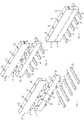
Fig. 1 eine Darstellung eines angedeuteten Sammelschienensystems mit einem noch nicht mit dem Sammelschienensystem verbundenen Einspeiseadapter sowie einer erfindungsgemäßen Überspannungsableiteranordnung im Zustand der noch nicht erfolgten Montagebewegung hinsichtlich der Leitungsaufnahmen im Einspeiseadapter; -
Fig. 2 eine Darstellung ähnlich derjenigen nachFig. 1 , wobei jedoch der Einspeiseadapter bereits mechanisch und elektrisch mit dem Sammelschienensystem verbunden ist und die Montagebewegung für die Überspannungsableiteranordnung noch aussteht; sowie -
Fig. 3 eine Darstellung im Zustand der mit dem Einspeiseadapter verbundenen Überspannungsableiteranordnung unter Nutzung der bei letzteren vorhandenen nasenartigen Steckkontakte, die unter einem Winkel abweichend von der Senkrechten bezüglich der Gehäuseunterseite verlaufen. - Die in den
Figuren 1 bis 3 gezeigte Überspannungsableiteranordnung 1 weist mehrere, in einem Gehäuse befindliche Überspannungsableiter mit entsprechender interner Verdrahtung auf. Über im Gehäuse ausgebildete Fenster kann der Funktionszustand der eingesetzten Überspannungsableiter kontrolliert und angezeigt werden. - Die Überspannungsableiteranordnung 1 dient insbesondere dem Schutz von Niederspannungssystemen.
- Da einer der Haupteinkopplungswege leitungsgebundener Störgrößen die in das System eingeführten Leitungen selbst bilden, ist eine Installation einer Überspannungsableiteranordnung unmittelbar am Gebäudeeintritt vorteilhaft.
- Gebäudeseitig sind Stromschienensysteme mit mehreren Stromschienen zur Energieverteilung bekannt. Die Stromschienensysteme weisen normgerecht beabstandete Stromschienen mit entsprechenden ebenfalls der Norm unterliegenden Stromschienenabmessungen auf.
- Ein Einspeiseadapter 4 kann nun in an sich bekannter Weise auf die entsprechenden Sammelschienen des Stromschienensystems 3 aufgesetzt und durch Verschiebung mechanisch befestigt und elektrisch kontaktiert werden. Die entsprechenden Einspeiseadapter 4 weisen eine Vielzahl von Anschlussöffnungen 5 auf, die üblicherweise zum Auflegen von Kabelenden genutzt werden.
- Die erfindungsgemäße Überspannungsableiteranordnung 1 besitzt eine Gehäuseunterseite, welche Ausnehmungen aufweist, durch die eine Vielzahl von elektrischen Steckkontakten 6 geführt sind.
- Diese Steckkontakte 6 sind bevorzugt nasenartig ausgebildet und verlaufen unter einem Winkel abweichend von der Senkrechten bezüglich der Gehäuseunterseite der Überspannungsableiteranordnung 1. Die jeweiligen Steckkontakte sind je Anordnungstyp identisch ausgebildet. Beispielsweise weisen die Steckkontakte 6 einen runden Querschnitt auf und können als SteckStift-Kontakte ausgebildet werden.
- Die Schräglage, der Abstand untereinander, die Länge und der Querschnitt der Steckkontakte 6 sind auf die Ausbildung des Einspeiseadapters 4 mit dortigen Öffnungen 5 ausgerichtet und entsprechend angepasst.
- Nachdem, wie in der
Figur 2 gezeigt, der entsprechende Einspeiseadapter 4 auf das Sammelschienensystem 3 aufgesetzt wurde, wird die Überspannungsableiteranordnung 1 mit den gleichsinnig schräg verlaufenden Steckkontakten 6 über eine horizontal zur Einspeiseadapteranordnung 4 ausgeführten Montagebewegung in die dortigen Öffnungen 5, welche beispielsweise die erwähnten Leitungsaufnahmen sind, eingeführt. Durch Schieben in leicht vertikaler Richtung nach unten erfolgt dann eine Verriegelung der Steckkontakte 6 im entsprechenden, auf den Sammelschienen 3 bereits aufgebrachten Einspeiseadapter 4. - Den Zustand im Ergebnis der ausgeführten Montage mit auf dem Einspeiseadapter 4 aufgesetzten Überspannungsableiter 1 zeigt die
Figur 3 .
Claims (7)
- Überspannungsableiteranordnung (1) mit mehreren, in einem Gehäuse befindlichen Überspannungsableitern und interner Verdrahtung zum Schutz von Niederspannungssystemen,wobei das Gehäuse eine Unterseite besitzt,wobei eine Vielzahl von elektrischen Steckkontakten (6) vorgesehen sind, die nasenartig ausgebildet sind und unter einem Winkel abweichend von der Senkrechten bezüglich der Gehäuseunterseite verlaufen,wobei die jeweiligen Steckkontakte (6) je Anordnungstyp identisch ausgebildet sind,dadurch gekennzeichnet, dassdie Gehäuseunterseite Ausnehmungen aufweist, durch die die Vielzahl von elektrischen Steckkontakten (6) geführt sind.
- Überspannungsableiteranordnung nach Anspruch 1, dadurch gekennzeichnet, dass die Steckkontakte (6) starr ausgebildet sind.
- Überspannungsableiteranordnung nach Anspruch 1 oder 2, dadurch gekennzeichnet, dass die Steckkontakte (6) einen runden Querschnitt aufweisen.
- Überspannungsableiteranordnung nach einem der vorangegangenen Ansprüche, dadurch gekennzeichnet, dass die Steckkontakte (6) als Steck-StiftKontakte ausgebildet sind.
- Überspannungsableiteranordnung nach einem der vorangegangenen Ansprüche, dadurch gekennzeichnet, dass die Schräglage, der Abstand untereinander, die Länge und der Querschnitt der Steckkontakte (6) auf die Ausbildung eines an sich bekannten Einspeiseadapters (4) für ein Sammelschienensystem (3) ausgerichtet sind.
- Überspannungsableiteranordnung nach einem der vorangegangenen Ansprüche, dadurch gekennzeichnet, dass die Steckkontakte (6) gleichsinnig schräg verlaufen und derart angeordnet sind, dass sie über eine horizontal zu einer Einspeiseadapterschiene ausgeführte Montagebewegung in dortige Leitungsaufnahmen einführbar sind.
- Überspannungsableiteranordnung nach einem der vorangegangenen Ansprüche, dadurch gekennzeichnet, dass die Überspannungsableiteranordnung (1) derart ausgebildet ist, dass eine Verriegelung der Steckkontakte (6) in einem auf Sammelschienen bereits aufgebrachten Einspeiseadapter (4) durch Schieben in leicht vertikaler Richtung nach unten erfolgt.
Applications Claiming Priority (2)
| Application Number | Priority Date | Filing Date | Title |
|---|---|---|---|
| DE102018111943 | 2018-05-17 | ||
| DE102018119992.9A DE102018119992A1 (de) | 2018-05-17 | 2018-08-16 | Überspannungsableiteranordnung mit mehreren, in einem Gehäuse befindlichen Überspannungsableitern und interner Verdrahtung zum Schutz von Niederspannungsversorgungssystemen |
Publications (2)
| Publication Number | Publication Date |
|---|---|
| EP3570392A1 EP3570392A1 (de) | 2019-11-20 |
| EP3570392B1 true EP3570392B1 (de) | 2022-07-27 |
Family
ID=63797530
Family Applications (1)
| Application Number | Title | Priority Date | Filing Date |
|---|---|---|---|
| EP19173278.3A Active EP3570392B1 (de) | 2018-05-17 | 2019-05-08 | Überspannungsableiteranordnung mit mehreren, in einem gehäuse befindlichen überspannungsableitern und interner verdrahtung zum schutz von niederspannungsversorgungssystemen |
Country Status (2)
| Country | Link |
|---|---|
| EP (1) | EP3570392B1 (de) |
| DE (1) | DE202018105277U1 (de) |
Families Citing this family (2)
| Publication number | Priority date | Publication date | Assignee | Title |
|---|---|---|---|---|
| DE102019106737A1 (de) * | 2019-03-18 | 2020-09-24 | Dehn Se + Co Kg | Überspannungsschutzgerät mit Spannungsabgriff |
| EP3713022B1 (de) * | 2019-03-18 | 2022-01-05 | DEHN SE + Co KG | Überspannungsschutzgerät |
Family Cites Families (4)
| Publication number | Priority date | Publication date | Assignee | Title |
|---|---|---|---|---|
| US2595658A (en) * | 1948-12-23 | 1952-05-06 | Cook Electric Co | Sealed arrester |
| DE1210063B (de) * | 1962-05-22 | 1966-02-03 | Siemens Ag | Reihenfassung fuer UEberspannungsableiter kleiner Bauart |
| DE3804294C1 (de) | 1988-02-12 | 1989-07-13 | Rittal-Werk Rudolf Loh Gmbh & Co Kg, 6342 Haiger, De | |
| DE102004037083B4 (de) | 2004-04-27 | 2016-07-28 | Dehn + Söhne Gmbh + Co. Kg | Überspannungsableiter-Anordnung mit einer als Bestandteil eines Gehäuses ausführbaren Trägerplatte |
-
2018
- 2018-09-14 DE DE202018105277.2U patent/DE202018105277U1/de active Active
-
2019
- 2019-05-08 EP EP19173278.3A patent/EP3570392B1/de active Active
Also Published As
| Publication number | Publication date |
|---|---|
| DE202018105277U1 (de) | 2018-09-25 |
| EP3570392A1 (de) | 2019-11-20 |
Similar Documents
| Publication | Publication Date | Title |
|---|---|---|
| DE3710896C2 (de) | ||
| EP3241261B1 (de) | Überspannungsschutzanordnung für die informations- und telekommunikationstechnik | |
| DE19617114C2 (de) | Erdungsmodul | |
| DE102008031200B4 (de) | Überspannungsschutzgerät | |
| DE102017111245A1 (de) | Stromverteiler | |
| DE102004037083B4 (de) | Überspannungsableiter-Anordnung mit einer als Bestandteil eines Gehäuses ausführbaren Trägerplatte | |
| DE2251020C3 (de) | Anschlußvorrichtung | |
| EP3570392A1 (de) | Überspannungsableiteranordnung mit mehreren, in einem gehäuse befindlichen überspannungsableitern und interner verdrahtung zum schutz von niederspannungsversorgungssystemen | |
| DE3837051C1 (en) | Overvoltage protection plug for a plurality of cables which are to be protected against overvoltages | |
| DE202018104832U1 (de) | Überspannungsableiteranordnung zum Schutz von Niederspannungsversorgungssystemen | |
| DE3412130C2 (de) | ||
| EP2922146A1 (de) | Vorrichtung zum Schutz gegen Überspannungen | |
| WO2009112320A1 (de) | Funktionserweiterbarer anschlussblock und modul | |
| EP1156558B1 (de) | Überspannungsschutzgerät | |
| DE202023101631U1 (de) | Zählersteckklemme, Baugruppe und Schaltschrank | |
| DE102018119992A1 (de) | Überspannungsableiteranordnung mit mehreren, in einem Gehäuse befindlichen Überspannungsableitern und interner Verdrahtung zum Schutz von Niederspannungsversorgungssystemen | |
| DE102005049873A1 (de) | Überspannungsableiter-Anordnung mit einer als Bestandteil eines Gehäuses ausführbaren Trägerplatte | |
| DE3905427C2 (de) | Überspannungsschutz für den Anschluß von Datenleitungen | |
| DE2201504B1 (de) | Anschlussleiste mit UEberspannungsschutzvorrichtung | |
| EP3879646A1 (de) | Aufnahmevorrichtung für eine überspannungsschutz-einheit | |
| DE202004011908U1 (de) | Überspannungsableiter-Anordnung mit einer als Bestandteil eines Gehäuses ausführbaren Trägerplatte | |
| DE102018120456A1 (de) | Überspannungsableiteranordnung zum Schutz von Niederspannungsversorgungssystemen | |
| EP1463074B1 (de) | Anordnung zur Verwendung bei einer elektrischen Installationsanlage | |
| DE202007006661U1 (de) | Steckdose | |
| DE102016117397A1 (de) | Sicherungsanordnung zur absicherung von aussenleitern einer elektrischen sicherungseinheit zur bildung eines gebäudeanschlusses |
Legal Events
| Date | Code | Title | Description |
|---|---|---|---|
| PUAI | Public reference made under article 153(3) epc to a published international application that has entered the european phase |
Free format text: ORIGINAL CODE: 0009012 |
|
| STAA | Information on the status of an ep patent application or granted ep patent |
Free format text: STATUS: THE APPLICATION HAS BEEN PUBLISHED |
|
| AK | Designated contracting states |
Kind code of ref document: A1 Designated state(s): AL AT BE BG CH CY CZ DE DK EE ES FI FR GB GR HR HU IE IS IT LI LT LU LV MC MK MT NL NO PL PT RO RS SE SI SK SM TR |
|
| AX | Request for extension of the european patent |
Extension state: BA ME |
|
| STAA | Information on the status of an ep patent application or granted ep patent |
Free format text: STATUS: REQUEST FOR EXAMINATION WAS MADE |
|
| 17P | Request for examination filed |
Effective date: 20191217 |
|
| RBV | Designated contracting states (corrected) |
Designated state(s): AL AT BE BG CH CY CZ DE DK EE ES FI FR GB GR HR HU IE IS IT LI LT LU LV MC MK MT NL NO PL PT RO RS SE SI SK SM TR |
|
| STAA | Information on the status of an ep patent application or granted ep patent |
Free format text: STATUS: EXAMINATION IS IN PROGRESS |
|
| 17Q | First examination report despatched |
Effective date: 20201021 |
|
| GRAP | Despatch of communication of intention to grant a patent |
Free format text: ORIGINAL CODE: EPIDOSNIGR1 |
|
| STAA | Information on the status of an ep patent application or granted ep patent |
Free format text: STATUS: GRANT OF PATENT IS INTENDED |
|
| INTG | Intention to grant announced |
Effective date: 20220218 |
|
| RAP1 | Party data changed (applicant data changed or rights of an application transferred) |
Owner name: DEHN SE |
|
| GRAS | Grant fee paid |
Free format text: ORIGINAL CODE: EPIDOSNIGR3 |
|
| GRAA | (expected) grant |
Free format text: ORIGINAL CODE: 0009210 |
|
| STAA | Information on the status of an ep patent application or granted ep patent |
Free format text: STATUS: THE PATENT HAS BEEN GRANTED |
|
| AK | Designated contracting states |
Kind code of ref document: B1 Designated state(s): AL AT BE BG CH CY CZ DE DK EE ES FI FR GB GR HR HU IE IS IT LI LT LU LV MC MK MT NL NO PL PT RO RS SE SI SK SM TR |
|
| REG | Reference to a national code |
Ref country code: CH Ref legal event code: EP |
|
| REG | Reference to a national code |
Ref country code: AT Ref legal event code: REF Ref document number: 1507719 Country of ref document: AT Kind code of ref document: T Effective date: 20220815 |
|
| REG | Reference to a national code |
Ref country code: DE Ref legal event code: R096 Ref document number: 502019005054 Country of ref document: DE |
|
| REG | Reference to a national code |
Ref country code: IE Ref legal event code: FG4D Free format text: LANGUAGE OF EP DOCUMENT: GERMAN |
|
| REG | Reference to a national code |
Ref country code: LT Ref legal event code: MG9D |
|
| REG | Reference to a national code |
Ref country code: NL Ref legal event code: MP Effective date: 20220727 |
|
| PG25 | Lapsed in a contracting state [announced via postgrant information from national office to epo] |
Ref country code: SE Free format text: LAPSE BECAUSE OF FAILURE TO SUBMIT A TRANSLATION OF THE DESCRIPTION OR TO PAY THE FEE WITHIN THE PRESCRIBED TIME-LIMIT Effective date: 20220727 Ref country code: RS Free format text: LAPSE BECAUSE OF FAILURE TO SUBMIT A TRANSLATION OF THE DESCRIPTION OR TO PAY THE FEE WITHIN THE PRESCRIBED TIME-LIMIT Effective date: 20220727 Ref country code: PT Free format text: LAPSE BECAUSE OF FAILURE TO SUBMIT A TRANSLATION OF THE DESCRIPTION OR TO PAY THE FEE WITHIN THE PRESCRIBED TIME-LIMIT Effective date: 20221128 Ref country code: NO Free format text: LAPSE BECAUSE OF FAILURE TO SUBMIT A TRANSLATION OF THE DESCRIPTION OR TO PAY THE FEE WITHIN THE PRESCRIBED TIME-LIMIT Effective date: 20221027 Ref country code: NL Free format text: LAPSE BECAUSE OF FAILURE TO SUBMIT A TRANSLATION OF THE DESCRIPTION OR TO PAY THE FEE WITHIN THE PRESCRIBED TIME-LIMIT Effective date: 20220727 Ref country code: LV Free format text: LAPSE BECAUSE OF FAILURE TO SUBMIT A TRANSLATION OF THE DESCRIPTION OR TO PAY THE FEE WITHIN THE PRESCRIBED TIME-LIMIT Effective date: 20220727 Ref country code: LT Free format text: LAPSE BECAUSE OF FAILURE TO SUBMIT A TRANSLATION OF THE DESCRIPTION OR TO PAY THE FEE WITHIN THE PRESCRIBED TIME-LIMIT Effective date: 20220727 Ref country code: FI Free format text: LAPSE BECAUSE OF FAILURE TO SUBMIT A TRANSLATION OF THE DESCRIPTION OR TO PAY THE FEE WITHIN THE PRESCRIBED TIME-LIMIT Effective date: 20220727 Ref country code: ES Free format text: LAPSE BECAUSE OF FAILURE TO SUBMIT A TRANSLATION OF THE DESCRIPTION OR TO PAY THE FEE WITHIN THE PRESCRIBED TIME-LIMIT Effective date: 20220727 |
|
| PG25 | Lapsed in a contracting state [announced via postgrant information from national office to epo] |
Ref country code: PL Free format text: LAPSE BECAUSE OF FAILURE TO SUBMIT A TRANSLATION OF THE DESCRIPTION OR TO PAY THE FEE WITHIN THE PRESCRIBED TIME-LIMIT Effective date: 20220727 Ref country code: IS Free format text: LAPSE BECAUSE OF FAILURE TO SUBMIT A TRANSLATION OF THE DESCRIPTION OR TO PAY THE FEE WITHIN THE PRESCRIBED TIME-LIMIT Effective date: 20221127 Ref country code: HR Free format text: LAPSE BECAUSE OF FAILURE TO SUBMIT A TRANSLATION OF THE DESCRIPTION OR TO PAY THE FEE WITHIN THE PRESCRIBED TIME-LIMIT Effective date: 20220727 Ref country code: GR Free format text: LAPSE BECAUSE OF FAILURE TO SUBMIT A TRANSLATION OF THE DESCRIPTION OR TO PAY THE FEE WITHIN THE PRESCRIBED TIME-LIMIT Effective date: 20221028 |
|
| PG25 | Lapsed in a contracting state [announced via postgrant information from national office to epo] |
Ref country code: SM Free format text: LAPSE BECAUSE OF FAILURE TO SUBMIT A TRANSLATION OF THE DESCRIPTION OR TO PAY THE FEE WITHIN THE PRESCRIBED TIME-LIMIT Effective date: 20220727 Ref country code: RO Free format text: LAPSE BECAUSE OF FAILURE TO SUBMIT A TRANSLATION OF THE DESCRIPTION OR TO PAY THE FEE WITHIN THE PRESCRIBED TIME-LIMIT Effective date: 20220727 Ref country code: DK Free format text: LAPSE BECAUSE OF FAILURE TO SUBMIT A TRANSLATION OF THE DESCRIPTION OR TO PAY THE FEE WITHIN THE PRESCRIBED TIME-LIMIT Effective date: 20220727 Ref country code: CZ Free format text: LAPSE BECAUSE OF FAILURE TO SUBMIT A TRANSLATION OF THE DESCRIPTION OR TO PAY THE FEE WITHIN THE PRESCRIBED TIME-LIMIT Effective date: 20220727 |
|
| REG | Reference to a national code |
Ref country code: DE Ref legal event code: R097 Ref document number: 502019005054 Country of ref document: DE |
|
| PG25 | Lapsed in a contracting state [announced via postgrant information from national office to epo] |
Ref country code: SK Free format text: LAPSE BECAUSE OF FAILURE TO SUBMIT A TRANSLATION OF THE DESCRIPTION OR TO PAY THE FEE WITHIN THE PRESCRIBED TIME-LIMIT Effective date: 20220727 Ref country code: EE Free format text: LAPSE BECAUSE OF FAILURE TO SUBMIT A TRANSLATION OF THE DESCRIPTION OR TO PAY THE FEE WITHIN THE PRESCRIBED TIME-LIMIT Effective date: 20220727 |
|
| PLBE | No opposition filed within time limit |
Free format text: ORIGINAL CODE: 0009261 |
|
| STAA | Information on the status of an ep patent application or granted ep patent |
Free format text: STATUS: NO OPPOSITION FILED WITHIN TIME LIMIT |
|
| PG25 | Lapsed in a contracting state [announced via postgrant information from national office to epo] |
Ref country code: AL Free format text: LAPSE BECAUSE OF FAILURE TO SUBMIT A TRANSLATION OF THE DESCRIPTION OR TO PAY THE FEE WITHIN THE PRESCRIBED TIME-LIMIT Effective date: 20220727 |
|
| 26N | No opposition filed |
Effective date: 20230502 |
|
| PG25 | Lapsed in a contracting state [announced via postgrant information from national office to epo] |
Ref country code: SI Free format text: LAPSE BECAUSE OF FAILURE TO SUBMIT A TRANSLATION OF THE DESCRIPTION OR TO PAY THE FEE WITHIN THE PRESCRIBED TIME-LIMIT Effective date: 20220727 |
|
| REG | Reference to a national code |
Ref country code: CH Ref legal event code: PL |
|
| PG25 | Lapsed in a contracting state [announced via postgrant information from national office to epo] |
Ref country code: MC Free format text: LAPSE BECAUSE OF FAILURE TO SUBMIT A TRANSLATION OF THE DESCRIPTION OR TO PAY THE FEE WITHIN THE PRESCRIBED TIME-LIMIT Effective date: 20220727 |
|
| GBPC | Gb: european patent ceased through non-payment of renewal fee |
Effective date: 20230508 |
|
| REG | Reference to a national code |
Ref country code: BE Ref legal event code: MM Effective date: 20230531 |
|
| PG25 | Lapsed in a contracting state [announced via postgrant information from national office to epo] |
Ref country code: MC Free format text: LAPSE BECAUSE OF FAILURE TO SUBMIT A TRANSLATION OF THE DESCRIPTION OR TO PAY THE FEE WITHIN THE PRESCRIBED TIME-LIMIT Effective date: 20220727 Ref country code: LU Free format text: LAPSE BECAUSE OF NON-PAYMENT OF DUE FEES Effective date: 20230508 Ref country code: LI Free format text: LAPSE BECAUSE OF NON-PAYMENT OF DUE FEES Effective date: 20230531 Ref country code: CH Free format text: LAPSE BECAUSE OF NON-PAYMENT OF DUE FEES Effective date: 20230531 |
|
| REG | Reference to a national code |
Ref country code: IE Ref legal event code: MM4A |
|
| PG25 | Lapsed in a contracting state [announced via postgrant information from national office to epo] |
Ref country code: IE Free format text: LAPSE BECAUSE OF NON-PAYMENT OF DUE FEES Effective date: 20230508 |
|
| PG25 | Lapsed in a contracting state [announced via postgrant information from national office to epo] |
Ref country code: IE Free format text: LAPSE BECAUSE OF NON-PAYMENT OF DUE FEES Effective date: 20230508 Ref country code: GB Free format text: LAPSE BECAUSE OF NON-PAYMENT OF DUE FEES Effective date: 20230508 |
|
| PG25 | Lapsed in a contracting state [announced via postgrant information from national office to epo] |
Ref country code: IT Free format text: LAPSE BECAUSE OF FAILURE TO SUBMIT A TRANSLATION OF THE DESCRIPTION OR TO PAY THE FEE WITHIN THE PRESCRIBED TIME-LIMIT Effective date: 20220727 Ref country code: FR Free format text: LAPSE BECAUSE OF NON-PAYMENT OF DUE FEES Effective date: 20230531 Ref country code: BE Free format text: LAPSE BECAUSE OF NON-PAYMENT OF DUE FEES Effective date: 20230531 |
|
| PG25 | Lapsed in a contracting state [announced via postgrant information from national office to epo] |
Ref country code: BG Free format text: LAPSE BECAUSE OF FAILURE TO SUBMIT A TRANSLATION OF THE DESCRIPTION OR TO PAY THE FEE WITHIN THE PRESCRIBED TIME-LIMIT Effective date: 20220727 |
|
| PG25 | Lapsed in a contracting state [announced via postgrant information from national office to epo] |
Ref country code: BG Free format text: LAPSE BECAUSE OF FAILURE TO SUBMIT A TRANSLATION OF THE DESCRIPTION OR TO PAY THE FEE WITHIN THE PRESCRIBED TIME-LIMIT Effective date: 20220727 |
|
| PGFP | Annual fee paid to national office [announced via postgrant information from national office to epo] |
Ref country code: DE Payment date: 20250519 Year of fee payment: 7 |
|
| REG | Reference to a national code |
Ref country code: AT Ref legal event code: MM01 Ref document number: 1507719 Country of ref document: AT Kind code of ref document: T Effective date: 20240508 |
|
| PG25 | Lapsed in a contracting state [announced via postgrant information from national office to epo] |
Ref country code: AT Free format text: LAPSE BECAUSE OF NON-PAYMENT OF DUE FEES Effective date: 20240508 |
|
| PG25 | Lapsed in a contracting state [announced via postgrant information from national office to epo] |
Ref country code: CY Free format text: LAPSE BECAUSE OF FAILURE TO SUBMIT A TRANSLATION OF THE DESCRIPTION OR TO PAY THE FEE WITHIN THE PRESCRIBED TIME-LIMIT; INVALID AB INITIO Effective date: 20190508 |
|
| PG25 | Lapsed in a contracting state [announced via postgrant information from national office to epo] |
Ref country code: HU Free format text: LAPSE BECAUSE OF FAILURE TO SUBMIT A TRANSLATION OF THE DESCRIPTION OR TO PAY THE FEE WITHIN THE PRESCRIBED TIME-LIMIT; INVALID AB INITIO Effective date: 20190508 |
|
| PG25 | Lapsed in a contracting state [announced via postgrant information from national office to epo] |
Ref country code: TR Free format text: LAPSE BECAUSE OF FAILURE TO SUBMIT A TRANSLATION OF THE DESCRIPTION OR TO PAY THE FEE WITHIN THE PRESCRIBED TIME-LIMIT Effective date: 20220727 |
|
| PGFP | Annual fee paid to national office [announced via postgrant information from national office to epo] |
Ref country code: AT Payment date: 20260410 Year of fee payment: 5 |