EP3569792B1 - Wall structure for building, installation device, and board construction method - Google Patents
Wall structure for building, installation device, and board construction method Download PDFInfo
- Publication number
- EP3569792B1 EP3569792B1 EP18819733.9A EP18819733A EP3569792B1 EP 3569792 B1 EP3569792 B1 EP 3569792B1 EP 18819733 A EP18819733 A EP 18819733A EP 3569792 B1 EP3569792 B1 EP 3569792B1
- Authority
- EP
- European Patent Office
- Prior art keywords
- extension
- mounting
- joining
- wall
- side wall
- Prior art date
- Legal status (The legal status is an assumption and is not a legal conclusion. Google has not performed a legal analysis and makes no representation as to the accuracy of the status listed.)
- Active
Links
- 238000010276 construction Methods 0.000 title claims description 45
- 238000009434 installation Methods 0.000 title 1
- 238000005304 joining Methods 0.000 claims description 216
- 239000000463 material Substances 0.000 claims description 108
- 238000000034 method Methods 0.000 claims description 3
- 239000011810 insulating material Substances 0.000 description 16
- 238000004519 manufacturing process Methods 0.000 description 10
- 238000005520 cutting process Methods 0.000 description 8
- 230000000694 effects Effects 0.000 description 8
- 238000005452 bending Methods 0.000 description 6
- 229910000831 Steel Inorganic materials 0.000 description 5
- 238000003825 pressing Methods 0.000 description 5
- 239000011347 resin Substances 0.000 description 5
- 229920005989 resin Polymers 0.000 description 5
- 239000010959 steel Substances 0.000 description 5
- 239000002023 wood Substances 0.000 description 5
- 238000005553 drilling Methods 0.000 description 4
- 238000010079 rubber tapping Methods 0.000 description 4
- 125000006850 spacer group Chemical group 0.000 description 4
- 239000011449 brick Substances 0.000 description 2
- 239000002184 metal Substances 0.000 description 2
- 239000004570 mortar (masonry) Substances 0.000 description 2
- 230000001151 other effect Effects 0.000 description 2
- 238000002407 reforming Methods 0.000 description 2
- 230000003014 reinforcing effect Effects 0.000 description 2
- 238000007789 sealing Methods 0.000 description 2
- ISWSIDIOOBJBQZ-UHFFFAOYSA-N Phenol Chemical compound OC1=CC=CC=C1 ISWSIDIOOBJBQZ-UHFFFAOYSA-N 0.000 description 1
- 229920005830 Polyurethane Foam Polymers 0.000 description 1
- 239000004568 cement Substances 0.000 description 1
- 229910010293 ceramic material Inorganic materials 0.000 description 1
- 238000007599 discharging Methods 0.000 description 1
- 239000006260 foam Substances 0.000 description 1
- 239000011491 glass wool Substances 0.000 description 1
- 238000003754 machining Methods 0.000 description 1
- 239000007769 metal material Substances 0.000 description 1
- 239000011490 mineral wool Substances 0.000 description 1
- 239000004745 nonwoven fabric Substances 0.000 description 1
- 239000004033 plastic Substances 0.000 description 1
- 229920003023 plastic Polymers 0.000 description 1
- 229920006327 polystyrene foam Polymers 0.000 description 1
- 239000011496 polyurethane foam Substances 0.000 description 1
- 239000011150 reinforced concrete Substances 0.000 description 1
- 239000003566 sealing material Substances 0.000 description 1
- 238000003466 welding Methods 0.000 description 1
Images


Classifications
-
- E—FIXED CONSTRUCTIONS
- E04—BUILDING
- E04F—FINISHING WORK ON BUILDINGS, e.g. STAIRS, FLOORS
- E04F13/00—Coverings or linings, e.g. for walls or ceilings
- E04F13/07—Coverings or linings, e.g. for walls or ceilings composed of covering or lining elements; Sub-structures therefor; Fastening means therefor
- E04F13/08—Coverings or linings, e.g. for walls or ceilings composed of covering or lining elements; Sub-structures therefor; Fastening means therefor composed of a plurality of similar covering or lining elements
- E04F13/0801—Separate fastening elements
- E04F13/0803—Separate fastening elements with load-supporting elongated furring elements between wall and covering elements
- E04F13/081—Separate fastening elements with load-supporting elongated furring elements between wall and covering elements with additional fastening elements between furring elements and covering elements
-
- E—FIXED CONSTRUCTIONS
- E04—BUILDING
- E04B—GENERAL BUILDING CONSTRUCTIONS; WALLS, e.g. PARTITIONS; ROOFS; FLOORS; CEILINGS; INSULATION OR OTHER PROTECTION OF BUILDINGS
- E04B2/00—Walls, e.g. partitions, for buildings; Wall construction with regard to insulation; Connections specially adapted to walls
- E04B2/56—Load-bearing walls of framework or pillarwork; Walls incorporating load-bearing elongated members
-
- E—FIXED CONSTRUCTIONS
- E04—BUILDING
- E04F—FINISHING WORK ON BUILDINGS, e.g. STAIRS, FLOORS
- E04F13/00—Coverings or linings, e.g. for walls or ceilings
- E04F13/07—Coverings or linings, e.g. for walls or ceilings composed of covering or lining elements; Sub-structures therefor; Fastening means therefor
- E04F13/08—Coverings or linings, e.g. for walls or ceilings composed of covering or lining elements; Sub-structures therefor; Fastening means therefor composed of a plurality of similar covering or lining elements
- E04F13/0801—Separate fastening elements
- E04F13/0803—Separate fastening elements with load-supporting elongated furring elements between wall and covering elements
- E04F13/0805—Separate fastening elements with load-supporting elongated furring elements between wall and covering elements with additional fastening elements between furring elements and the wall
- E04F13/0807—Separate fastening elements with load-supporting elongated furring elements between wall and covering elements with additional fastening elements between furring elements and the wall adjustable perpendicular to the wall
-
- E—FIXED CONSTRUCTIONS
- E04—BUILDING
- E04F—FINISHING WORK ON BUILDINGS, e.g. STAIRS, FLOORS
- E04F13/00—Coverings or linings, e.g. for walls or ceilings
- E04F13/07—Coverings or linings, e.g. for walls or ceilings composed of covering or lining elements; Sub-structures therefor; Fastening means therefor
- E04F13/08—Coverings or linings, e.g. for walls or ceilings composed of covering or lining elements; Sub-structures therefor; Fastening means therefor composed of a plurality of similar covering or lining elements
- E04F13/0801—Separate fastening elements
- E04F13/0803—Separate fastening elements with load-supporting elongated furring elements between wall and covering elements
- E04F13/081—Separate fastening elements with load-supporting elongated furring elements between wall and covering elements with additional fastening elements between furring elements and covering elements
- E04F13/0821—Separate fastening elements with load-supporting elongated furring elements between wall and covering elements with additional fastening elements between furring elements and covering elements the additional fastening elements located in-between two adjacent covering elements
- E04F13/0826—Separate fastening elements with load-supporting elongated furring elements between wall and covering elements with additional fastening elements between furring elements and covering elements the additional fastening elements located in-between two adjacent covering elements engaging side grooves running along the whole length of the covering elements
Definitions
- the present invention relates to a wall structure for a building.
- Patent Documents 1 to 3 mentioned below disclose a conventional wall structure for a building.
- the wall structure disclosed in Patent Document 1 multiple bracket base materials that extend in the left-right direction are arranged on a wall surface of a structural body. Multiple brackets are fixed to the bracket base materials. Also, multiple vertical furring strips that extend in the up-down direction along the wall surface are arranged extending across the multiple brackets. Furthermore, multiple board materials are attached to the vertical furring strips, and the board materials cover the wall surface.
- a bolt fixing hole is provided through a mounting portion of a base member, and an elongated hole is provided through a slide portion of a slide member. Then, when a male screw is inserted through the bolt fixing hole and the elongated hole and screwed into a slide member fixing nut, unevenness in the wall surface can be adjusted by shifting the slide portion with respect to the mounting portion.
- a bolt fixing hole is provided through a standing portion of a first bracket member, and an elongated hole is provided through a slide portion of a second bracket member. Then, when a bolt is inserted through the bolt fixing hole and the elongated hole and is screwed into a nut, unevenness of the wall surface can be adjusted by shifting the slide portion with respect to the standing portion.
- Patent Document 4 discloses a mounting bracket for a facade substructure.
- Patent Document 5 describes an attachment apparatus according to the preamble of claim 1, the attachment apparatus including a bracket and an extension member. Document 5 also discloses a wall structure and a method using such an attachment apparatus.
- the present invention was made in view of the foregoing conventional circumstances, and a problem to be solved is to provide a wall structure for a building, an attachment apparatus, and a board material construction method, according to which construction is simple and fast, and board materials can be stably supported.
- the present invention provides an attachment apparatus according to appended claim 1 and a wall structure for a building according to appended claim 2.
- brackets each having first and second side wall portions that extend continuously from at least portions of both side edges of the first portion to at least portions of both side edges of the second portion are used. For this reason, unevenness in the wall surface of the structural body can be adjusted when the first joining portion of the first support body is mounted on the mounting surface, and the mounting portion of the bracket and the first joining portion of the first support body can be fastened to each other using the first drill screw at that position.
- the bracket reinforced by the first and second side wall portions can withstand the load. For this reason, with this wall structure, the unevenness adjustment of the wall surface and the arrangement of the first support body can be implemented in the same step, and therefore construction is simpler and faster.
- construction is simple and fast, and the board material can be stably supported.
- the configuration in which "the board material is attached directly to the side of at least two of the first support bodies that is opposite to the wall surface, and the board material is arranged directly on the second joining portions of the first support bodies” specifically means a configuration in which the board material is arranged on the second joining portions without a support body other than the first support bodies being interposed, and the board material is attached directly to the first support bodies using a fastening member, an attachment tool, or the like, such as a screw.
- a fastening member, an attachment tool, or the like such as a screw.
- the configuration in which "the board material is attached indirectly to the side of at least two first support bodies that is opposite to the wall surface and the board material is arranged indirectly on the second joining portions of the first support bodies” specifically means a configuration in which the board material is arranged on the second joining portions with a support body other than the first support bodies interposed, the other support body is attached to the first support bodies using a fastening member such as a screw, and furthermore, the board material is attached to the other support body using a fastening member such as a screw, an attachment tool, or the like.
- the wall structure for a building includes a plurality of second support bodies that extend in a second direction intersecting the first support bodies along the wall surface and are arranged extending across at least two of the first support bodies. It is desirable that the second support bodies are arranged on the second joining portions. Also, it is desirable that the board materials are attached to at least two of the second support bodies.
- the unevenness adjustment of the wall surface can be implemented even more preferably, and the board material can be supported even more stably.
- the brackets each include a protruding portion that is provided between the first side wall portion and the second side wall portion, extends continuously from at least a portion of the first portion to at least a portion of the second portion, and protrudes toward the narrow angle side.
- the first portion and second portion of the bracket and the connection portions of the first portion and second portion can be reinforced by the protruding portion.
- the protrusion lengths of the first side wall portion and the second side wall portion can be suppressed to be small. Accordingly, if the heat insulating material is arranged around the bracket, it is possible to suppress a case in which a gap occurs between the narrow angle side of the second portion of the bracket and the heat insulating material using the first side wall portion and the second side wall portion.
- the protruding portion extends to the approximate center of the second portion.
- the mounting surface is a flat surface formed in a range of the second portion that is farther from the first portion than the protruding portion.
- the mounting surface is a flat surface due to being formed in a range of the second portion in which the protruding portion does not exist, and therefore the first joining portion of the first support body can be reliably mounted on the mounting surface, and the mounting portion and the first joining portion can be reliably fastened to each other using the first drill screw.
- a first height to which the protrusion portion protrudes with respect to the mounting surface is set to be less than or equal to a second height to which the first side wall portion and the second side wall portion protrude with respect to the mounting surface.
- the second height can be reduced according to the reinforcing effect of the protruding portion on the bracket, and it is possible to suppress a case in which the first and second side wall portions and the protruding portion hinder construction. Also, if the heat insulating material is arranged around the bracket, it is possible to effectively suppress a case in which a gap occurs between the heat insulating material and the bracket near the first and second side wall portion on the narrow angle side of the second portion of the bracket.
- the mounting portion is provided with a main elongated hole that extends away from the fixing portion.
- the first support body when the mounting portion of the bracket and the first joining portion of the first support body are to be fastened to each other, the first support body can be temporarily fastened to the mounting portion by inserting the first drill screw into the main elongated hole of the mounting portion and thereafter shallowly screwing the first drill screw into the first joining portion. Then, in this state, the mounting portion and the first joining portion can be reliably fastened to each other by positioning the first support body through shifting in a direction of moving away from the fixing portion or the opposite direction, and thereafter completely screwing the first drill screw into the first joining portion. As a result, the positioning of the first support body for adjusting the unevenness of the wall surface can be performed precisely and easily, and thus simplification of the task can be realized.
- the mounting portion is provided with at least one main circular hole arranged at a position away from the main elongated hole in a direction intersecting a longitudinal direction of the main elongated hole.
- the first drill screw is inserted into the main elongated hole of the mounting portion and positioning adjustment of the first support body is performed, and the mounting portion and the first joining portion are reliably fastened to each other, and thereafter the mounting portion and the first joining portion can be even more reliably fastened to each other by inserting another first drill screw into the main circular hole of the mounting portion and screwing the other first drill screw into the first joining portion.
- the other first drill screw need not drill a pilot hole in the mounting portion, and therefore the task of fastening using the other first drill screw can be performed easily.
- the wall structure for a building includes an extension member configured to be arranged between the mounting portion of the bracket and the first joining portion of the first support body.
- the extension member includes: an extension mounting portion that is configured to be mounted on the mounting surface, extends away from the first portion, and includes an extension mounting surface that faces the same side as the mounting surface such that the first joining portion is mounted thereon; a first extension side wall portion that protrudes in the same direction as the first side wall portion from one side edge of the extension mounting portion, and is adjacent to the first side wall portion; and a second extension side wall portion that protrudes in the same direction as the second side wall portion from another side edge of the extension mounting portion, and is adjacent to the second side wall portion.
- the fastening members include: a second drill screw for fastening the mounting portion and the extension mounting portion to each other in a direction perpendicular to the mounting surface; and a third drill screw for fastening the extension mounting portion and the first joining portion to each other in a direction perpendicular to the extension mounting surface.
- the unevenness is adjusted using the extension member, and then the bracket and the first support body can be fastened to each other. Accordingly, it is possible to reliably realize a case in which the first support body is arranged straight in a first direction, and as a result, the board material can be arranged on the structural body with high accuracy. Also, due to the first and second extension side wall portions sandwiching the first and second side wall portions, horizontal shifting of the extension member with respect to the mounting portion can be suppressed when the extension member slides in the direction toward or away from the wall surface, and when the second drill screw fastens the mounting portion and the extension mounting portion to each other.
- the extension member reinforced by the first and second extension side wall portions can withstand the load.
- the extension member reinforced by the first and second extension side wall portions can withstand the load.
- extension mounting portion is provided with an auxiliary elongated hole that extends away from the first portion.
- the first support body when the extension mounting portion of the extension member and the first joining portion of the first support body are fastened to each other, the first support body can be temporarily fastened to the extension mounting portion by inserting the third drill screw into the auxiliary elongated hole of the extension mounting portion and thereafter shallowly screwing the third drill screw into the first joining portion. Then, in that state, the extension mounting portion and the first joining portion can be reliably fastened to each other by positioning the first support body through shifting in the direction of moving away from the first portion or the opposite direction and thereafter completely screwing the third drill screw into the first joining portion. As a result, the positioning of the first support body for adjusting the unevenness of the wall surface can be performed precisely and easily, and thus simplification of the task can be realized.
- the extension mounting portion is provided with at least one auxiliary circular hole arranged at a position away from the auxiliary elongated hole in a direction intersecting the longitudinal direction of the auxiliary elongated hole.
- the third drill screw is inserted into the auxiliary elongated hole of the extension mounting portion, and positioning adjustment of the first support body is performed, whereupon the extension mounting portion and the first joining portion are reliably fastened to each other, and thereafter the extension mounting portion and the first joining portion can be even more reliably fastened to each other by inserting another third drill screw into the auxiliary circular hole of the extension mounting portion and screwing the other third drill screw into the first joining portion.
- the other third drill screw need not drill a pilot hole in the extension mounting portion, and therefore the task of fastening using the other third drill screw can be performed easily.
- the auxiliary elongated hole and the auxiliary circular hole are arranged at positions shifted with respect to the main elongated hole.
- the auxiliary elongated hole and the auxiliary circular hole are arranged at positions shifted with respect to the main circular hole.
- the extension member when the mounting portion of the bracket and the extension mounting portion of the extension member are fastened to each other, the extension member can be temporarily fastened to the mounting portion by inserting the second drill screw into the main elongated hole of the mounting portion and thereafter shallowly screwing the second drill screw into the extension mounting portion. Then, in this state, the mounting portion and the extension mounting portion can be reliably fastened to each other by positioning the extension member through shifting in the direction of moving away from the first portion or the opposite direction and thereafter completely screwing the second drill screw into the extension mounting portion. Thereafter, the mounting portion and the extension mounting portion can be even more reliably fastened to each other by inserting another second drill screw into the main circular hole of the mounting portion and screwing the other second drill screw into the extension mounting portion.
- the other second drill screw need not drill a pilot hole in the mounting portion, and therefore the task of fastening using the other second drill screw can be performed easily.
- the task of fastening with the third drill screw, using the auxiliary elongated hole and the auxiliary circular hole is as described in the ninth and tenth aspects of the present invention.
- the auxiliary elongated hole and the auxiliary circular hole are arranged at positions shifted with respect to the main elongated hole, and the auxiliary elongated hole and the auxiliary circular hole are arranged at positions shifted with respect to the main circular hole, whereby the auxiliary elongated hole and the auxiliary circular hole do not hinder each other's effect.
- the positioning of the first support body for adjusting the unevenness of the wall surface can be performed even more precisely and easily, and thus further simplification of the task can be realized.
- the following work procedure can also be used, with consideration given to ease of performing the task. That is, when the mounting portion of the bracket and the extension mounting portion of the extension member, which overlaps the mounting portion from above, are to be fastened to each other, the extension member can be temporarily fastened to the mounting portion by inserting the second drill screw into the auxiliary elongated hole of the extension mounting portion and thereafter shallowly screwing the second drill screw into the mounting portion. Then, in this state, the mounting portion and the extension mounting portion can be reliably fastened to each other by positioning the extension member through shifting in the direction of moving away from the first portion or the opposite direction and thereafter completely screwing the second drill screw into the mounting portion. Thereafter, the mounting portion and the extension mounting portion can be even more reliably fastened to each other by inserting another second drill screw into the auxiliary circular hole of the extension mounting portion and screwing the second drill screw into the mounting portion.
- the board materials each have a quadrilateral shape with four first to fourth end portions. It is desirable that in each of the board materials, the first end portion of the board material includes a first shiplap joining portion that is recessed from a back surface to a front surface of the board material and extends along the first end portion. It is desirable that the second end portion of the board material opposing the first end portion includes a second shiplap joining portion that is recessed from the front surface to the back surface of the board material and extends along the second end portion . It is desirable that the third end portion that intersects the first end portion and the second end portion of the board material includes a third shiplap joining portion that is recessed from the front surface to the back surface of the board material and extends along the third end portion. Also, it is desirable that the fourth end portion of the board material that opposes the third end portion includes a fourth shiplap joining portion that is recessed from the back surface to the front surface of the board material and extends along the fourth end portion.
- the board material has a so-called "four-way shiplap structure", and a joining portion in one direction, such as a joining portion in vertical direction, is formed due to the first shiplap joining portion and the second shiplap joining portion overlapping. Also, a joining portion in another direction, such as a joining portion in a horizontal direction, is formed due to the third shiplap joining portion and the fourth shiplap joining portion overlapping. Accordingly, gaps between board materials that are adjacent in the vertical direction and the horizontal direction are not likely to occur. For this reason, the joining and waterproof property of the board materials can be ensured without using sealing or the like. Also, the quality of the appearance of the joining portions of the board materials is improved. Accordingly, it is possible to provide a high-quality wall structure for which construction is simple.
- the invention further provides an attachment apparatus according to appended claim 1.
- the bracket includes a protrusion portion that is provided between the first side wall portion and the second side wall portion, extends continuously from at least a portion of the first portion to at least a portion of the second portion, and protrudes toward the narrow angle side.
- the attachment apparatus includes an extension member configured to be used along with the bracket.
- the extension member includes: an extension mounting portion that includes an extension mounting surface and is to be mounted on the mounting surface; a first extension side wall portion that protrudes from one side edge of the extension mounting portion; and a second extension side wall portion that protrudes from another side edge of the extension mounting portion.
- the extension mounting portion is provided with an auxiliary elongated hole that extends in the longitudinal direction of the extension mounting surface, and at least one auxiliary circular hole that is arranged at a position away from the auxiliary elongated hole in a direction intersecting the longitudinal direction of the auxiliary elongated hole.
- the extension mounting surface faces the same side as the mounting surface
- the first extension side wall portion is adjacent to the first side wall portion
- the second extension side wall portion is adjacent to the second side wall portion
- the auxiliary elongated hole and the auxiliary circular hole are arranged at positions shifted with respect to the main elongated hole
- the auxiliary elongated hole and the auxiliary circular hole are arranged at positions shifted with respect to the main circular hole.
- the invention further provides a board material construction method according to appended claim 6.
- the board material construction method of the present invention similarly to the wall structure for a building according to the present invention, construction is simple and fast, and the board material can be stably supported.
- the fourth step includes: a fifth step of arranging a plurality of second support bodies in a manner extending across at least two of the first support bodies, the plurality of second support bodies extending in a second direction intersecting the first support bodies along the wall surface; and a sixth step of attaching the board materials to at least two of the second support bodies. Also, it is desirable that in the fifth step, the second support bodies are arranged on the second joining portions of the first support bodies.
- the mounting portion is provided with a main elongated hole that extends away from the fixing portion. It is desirable that in the third step, the first drill screw is inserted into the main elongated hole and thereafter is shallowly screwed into the first joining portion, then the first support body is positioned through shifting in a direction of moving away from the fixing portion or the opposite direction, and then the first drill screw is completely screwed into the first joining portion.
- an extension member is arranged between the mounting portion of the bracket and the first joining portion of the first support body.
- the extension member includes: an extension mounting portion that is configured to be mounted on the mounting surface, extends away from the first portion, and includes an extension mounting surface that faces the same side as the mounting surface and on which the first joining portion is to be mounted; a first extension side wall portion that protrudes in the same direction as the first side wall portion from one side edge of the extension mounting portion, and is adjacent to the first side wall portion; and a second extension side wall portion that protrudes in the same direction as the second side wall portion from another side edge of the extension mounting portion, and is adjacent to the second side wall portion.
- the fastening member fastens the mounting portion and the extension mounting portion to each other in a direction perpendicular to the mounting surface using a second drill screw, and the fastening member fastens the extension mounting portion and the first joining portion to each other in a direction perpendicular to the extension mounting surface using a third drill screw.
- the extension mounting portion is provided with an auxiliary elongated hole that extends away from the first portion. Also, it is desirable that in the third step, the third drill screw is inserted into the auxiliary elongated hole and thereafter shallowly screwed into the first joining portion, then the first support body is positioned through shifting in the direction of moving away from the first portion or the opposite direction, and then the third drill screw is completely screwed into the first joining portion.
- construction is simple and fast, and board materials can be stably supported.
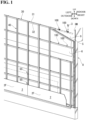
- FIG. 1 a vertical upward direction is upward, and a vertical downward direction is downward. Also, in a direction from outside to inside the room in FIG. 1 , a horizontal leftward direction is leftward, and a horizontal rightward direction is rightward. Also, the directions shown in FIG. 2 and onward correspond to those in FIG. 1 .
- a wall structure of a first example is an example of a specific form of a wall structure for a building.
- the wall structure is obtained by attaching multiple outer wall boards 2 to a structural body 8 included in a building such as a residence, a facility, or a warehouse.
- the structural body 8 may also be included in a newly-built building, or may be included in an already-built building to be subjected to construction work for reforming the building exterior.
- the outer wall boards 2 are an example of board materials. As shown in FIG. 2 , FIG. 3 , and the like, the outer wall boards 2 are board materials that have high strength and rigidity and that form an outer wall of a building.
- the outer wall boards 2 may also be used in a newly-built building, or may be for reforming for improving design by covering a wall surface of an already-built building.
- the board material is not limited to an outer wall board, and for example, may also be a decorative board for covering the exterior of a building, a structure panel for indoor use, an interior board, or the like.
- the structural body 8 is a strong frame made of reinforced concrete or bricks, and mortar 8M is applied to the outermost layer on an outdoor side of the frame.
- the structural body 8 has a wall surface 9 that faces an outdoor direction.
- the structural body is not limited to the present embodiment, and for example, the mortar 8M of the structural body 8 is omitted in some cases.
- the structural body may also be included in a wooden building built using wood post and beam construction, timber frame construction, or the like.
- Brackets 100, a heat insulating material 5, waterproof sheets 6, horizontal support bodies 30, vertical support bodies 40, and first attachment tools 50 are arranged between the structural body 8 and the outer wall boards 2.
- the horizontal support bodies 30 are an example of first support bodies.
- the vertical support bodies 40 are an example of second support bodies.
- brackets 100 are arranged on the wall surface 9, separated from each other by predetermined intervals in the up-down direction and the left-right direction.
- the spacers 3 shown in FIG. 1 are arranged as needed between the brackets 100 and the wall surface 9.
- the spacers 3 are approximately rectangular boards with U-shaped grooves cut out. Due to the spacers 3 being made of resin, it is possible to block heat bridges between the brackets 100 and the wall surface 9. Also, by selecting the thickness and number of the spacers 3 according to the unevenness of the wall surface 9, the unevenness of the wall surface 9 can be adjusted to a certain extent.
- the bracket 100 is manufactured due to a metal board material being subjected to bending, pressing, and the like.
- a steel board material with a thickness of about 2 mm is subjected to bending, pressing, and the like, and is formed into a three-dimensional shape without performing partial welding.
- the material and manufacturing method of the bracket 100 is not limited to those described above, and various materials and manufacturing methods can be selected as appropriate. Also, during machining of the bracket 100, abutting end portions of two separately-bent protruding pieces are welded together, whereby the protruding pieces can be made continuous.
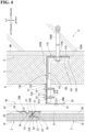
- the up-down direction, the left-right direction, and the indoor-outdoor direction are defined with reference to the orientation of the brackets 100 in the state of being arranged on the wall surface 9, as shown in FIG. 4 and the like.
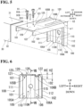
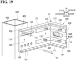
- the bracket 100 includes a first portion 110, a second portion 120, a first side wall portion 101, a second side wall portion 102, protruding portions 105 and 106, and a mounting portion 125.
- the first portion 110 is approximately square-shaped, and a circular hole 110H is provided through the approximate center thereof.
- the first portion 110 includes a fixing portion 115.
- the fixing portion 115 forms a flat surface that surrounds the circular hole 110H. As shown in FIG. 4 , the fixing portion 115 is brought into contact with the wall surface 9 in a state of extending in the up-down direction and the left-right direction, an anchor bolt 100B is inserted through the circular hole 110H, and the anchor bolt 100B is further fastened to the side wall 9. Accordingly, the fixing portion 115 is fixed to the side wall 9.
- the second portion 120 is approximately rectangular and is connected to the upper edge of the first portion 110.
- the second portion 120 is bent from the first portion 110 in the outdoor direction and extends away from the fixing portion 115.
- the narrow angle of the angle formed by the first portion 110 and the second portion 120 is ⁇ 1.
- the narrow angle ⁇ 1 is set to be an approximate right angle.
- a length L120 in the indoor-outdoor direction of the second portion 120 is set to be approximately twice a length L110 in the up-down direction of the first portion 110 for example, but there is no limitation to this configuration, and the length L120 may be greater or less than this length.
- the length L120 can also be set to be equal to the length L110.
- the first side wall portion 101 is approximately L-shaped due to connection between a board-shaped portion that is connected to the entire left side edge 111 of the first portion 110 and is bent at an approximate right angle in the outdoor direction, and a board-shaped portion that is connected to the entire left side edge 121 of the second portion 120 and is bent at an approximate right angle downward. That is, the first side wall portion 101 extends continuously from the lower end of the left side edge 111 of the first portion 110 to the leading end of the left side edge 121 of the second portion 120 and protrudes to the narrow angle ⁇ 1 side.
- the second side wall portion 102 is approximately L-shaped due to connection between a board-shaped portion that is connected to the entire right side edge 112 of the first portion 110 and is bent at an approximate right angle in the outdoor direction, and a board-shaped portion that is connected to the entire right side edge 122 of the second portion 120 and is bent at an approximate right angle downward. That is, the second side wall portion 102 extends continuously from the lower end of the right side edge 112 of the first portion 110 to the leading end of the right side edge 122 of the second portion 120 and protrudes to the narrow angle ⁇ 1 side.
- a corner portion C1 formed by the first portion 110, the second portion 120, and the first side wall portion 101 is formed seamlessly through pressing.
- a corner portion C2 formed by the first portion 110, the second portion 120, and the second side wall portion 102 is also formed seamlessly through pressing.
- a rib 105A that has a U-shaped cross-section is formed so as to protrude in the outdoor direction between the first side wall portion 101 and the circular hole 110H and extend in the up-down direction.
- a rib 105B that has a U-shaped cross-section and connects to the rib 105A is formed so as to protrude downward and extend in the indoor-outdoor direction.
- the protruding portion 105 on the left is formed by the ribs 105A and 105B.
- a rib 106A that has a U-shaped cross-section is formed so as to protrude in the outdoor direction between the second side wall portion 102 and the circular hole 110H and extend in the up-down direction.
- a rib 106B that has a U-shaped cross-section and connects to the rib 106A is formed so as to protrude downward and extend in the indoor-outdoor direction.
- the protruding portion 106 on the right is formed by the ribs 106A and 106B.
- the protruding portions 105 and 106 each extend upward from the lower edge of the first portion 110, are bent in the outdoor direction at the upper edge of the first portion 110, extend in the outdoor direction, and end at the approximate center of the second portion 120.
- the protruding portions 105 and 106 are provided between the first side wall portion 101 and the second side wall portion 102, extend continuously from the lower edge of the first portion 110 to the approximate center of the second portion 120, and protrude to the narrow angle ⁇ 1 side.
- the mounting portion 125 is provided on the leading edge side of the second portion 120.
- the mounting portion 125 includes a mounting surface 126.
- the mounting surface 126 is a flat surface that is surrounded by the leading edge of the second portion 120, the left-side edge 121, the right-side edge 122, and the leading ends of the protruding portions 105 and 106 and faces the side opposite to the first side wall portion 101 and the second side wall portion 102. That is, the mounting surface 126 is an upward-facing flat surface formed in a range of the second portion 120 that is farther from the first portion 110 than the leading ends of the protruding portions 105 and 106.
- a first height H1 to which the protruding portions 105 and 106 protrude downward with respect to the mounting surface 126 is set to be less than or equal to a second height H2 to which the first side wall portion 101 and the second side wall portion 102 protrude downward with respect to the mounting surface 126.
- the heat insulating material 5 is arranged along the wall surface 9 of the structural body 8.
- the heat insulating material 5 is, for example, a fibrous heat insulating material such as rock wool or glass wool, a plastic foam-type heat insulating material such as polyurethane foam, phenol foam, or polystyrene foam, or the like.
- the heat insulating material 5 is arranged such that portions that interfere with the brackets 100 are removed and the leading edge sides of the mounting portions 125 of the brackets 100 are exposed. Note that the heat insulating material 5 can also be omitted, depending on the construction state or the like of the structural body 8.
- the waterproof sheets 6 are laid on the front surface of the heat insulating material 5.
- the waterproof sheets 6 are composed of waterproof paper, film, nonwoven fabric, or the like, and some are moisture-permeable instead of being waterproof. Note that the waterproof sheets 6 can also be omitted, depending on the construction state or the like of the structural body 8. Notches are formed in the waterproof sheets 6 at locations corresponding to the second portions 120 of the brackets 100, and the waterproof sheets 6 are arranged so as to cause the leading edge sides of the mounting portions 125 of the brackets 100 to protrude.
- the horizontal support body 30 is an elongated board material having an L-shaped cross-section.
- the horizontal support body 30 includes a first joining portion 31 and a second joining portion 32.
- the second joining portion 32 connects to one edge of the flat board-shaped first joining portion 31, and extends in a flat board shape in a direction approximately orthogonal to the first joining portion 31.
- the horizontal support body 30 is manufactured by performing bending and the like on a steel board material, for example. Note that the material and manufacturing method of the horizontal support body 30 are not limited to those described above, and various types of materials including resin, wood, and the like, and manufacturing methods can be selected as appropriate.
- the multiple horizontal support bodies 30 are arranged on the wall surface 9 in a state of being separated from each other at a predetermined interval in the up-down direction on the outdoor side with respect to the waterproof sheets 6, and extending in the left-right direction along the wall surface 9.
- a horizontal support body 30 is arranged extending across at least two brackets 100.
- the bracket 100 and the horizontal support body 30 are fastened to each other by first drill screws 91.
- the left-right direction is an example of a first direction.
- the first drill screws 91 are an example of fastening members.
- the horizontal support bodies 30 are put in a state in which the first joining portions 31 are mounted on the mounting surfaces 126 of the brackets 100 and the second joining portions 32 are located on the side opposite to the wall surface 9 with respect to the first joining portions 31.
- a known drill screw in which a drill such as a cutting blade portion or a tapered portion is formed at the leading end of a screw, and which performs pilot hole drilling, tapping, and fastening with the screw itself, is used as the first drill screw 91.
- the first drill screw 91 includes a screw portion 91B, a cutting blade portion 91C formed on the leading end of the screw portion 91B, and a head portion 91A that connects to the base of the screw portion 91B.
- unevenness in the wall surface 9 is adjusted by shifting the position of the first joining portion 31 of the horizontal support body 30 mounted on the mounting surface 126 in the indoor-outdoor direction according to the protrusion and recession of the wall surface 9 of the structural body 8.
- the first drill screw 91 is held in an electric screwdriver (not shown) by fitting the leading end portion of the electric screwdriver (not shown) into a groove provided in the head portion 91A of the first drill screw 91.
- the cutting blade portion 91C of the first drill screw 91 is brought into contact with the first joining portion 31 from above, and the fastening position is determined.
- the electric screwdriver (not shown) is operated while causing a downward load F1 to act on the first drill screw 91.
- the cutting blade portion 91C rotates while being pressed into the first joining portion 31 and the mounting portion 125, and thereby cuts the first joining portion 31 and the mounting portion 125 while discharging cutting debris and drills pilot holes in the first joining portion 31 and the mounting portion 125.
- the screw portion 91B performs tapping using a portion adjacent to the cutting blade portion 91C and performs fastening on the first joining portion 31 and the mounting portion 125 using a portion located on the head portion 91A side with respect to the portion adjacent to the cutting blade portion 91C.
- the downward load F1 reaches its maximum when the cutting blade portion 91C opens a pilot hole in the first joining portion 31 and the mounting portion 125.
- the first drill screw 91 penetrates through the mounting portion 125 and the first joining portion 31 in the up-down direction, which is perpendicular to the mounting surface 126, and fastens the mounting portion 125 and the first joining portion 31 to each other.
- the present invention also encompasses a configuration in which a pilot hole is drilled in advance at a position corresponding to the fastening location of the first joining portion 31.
- the vertical support body 40 is an elongated board material having a hat-shaped cross-section.
- the vertical support body 40 includes a central board portion 41 and a pair of side board portions 42.
- the pair of side board portions 42 are connected with a level difference to both side edges of the flat board-shaped central board portion, and extend in flat board shapes in the direction away from each other.
- the vertical support body 40 is manufactured by performing bending and the like on a steel board material, for example. Note that the material and manufacturing method of the vertical support body 40 are not limited to those described above, and various types of materials including resin, wood, and the like, and manufacturing methods can be selected as appropriate.
- the multiple vertical support bodies 40 are arranged on the wall surface 9 in a state of being separated from each other by a predetermined interval in the left-right direction on the outdoor side with respect to the second joining portions 32 of the horizontal support bodies 30, and extending in the up-down direction along the wall surface 9.
- the vertical support bodies 40 are each arranged extending across at least two horizontal support bodies 30.
- the pair of side board portions 42 of the vertical support body 40 and the second joining portion 32 of the horizontal support body 30 are fastened to each other by the screw 40B.
- the up-down direction is an example of a second direction.
- the screws 40B shown in FIG. 4 are also drill screws. If drill screws are not used, a task of drilling pilot holes in the side board portion 42 and the second joining portion 32 is needed before the task of fastening the pair of side board portions 42 of the vertical support body 40 and the second joining portion 32 of the horizontal support body 30 to each other using the screws 40B.
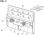
- the first attachment tool 50 includes a first fixing portion 55, a first upper contact portion 56, a first lower contact portion 57, a first bearing portion 51, first upper locking portions 52, a first lower locking portion 53, and a standing piece 59.
- the first fixing portion 55 forms a flat surface that can come into contact with the central board portion 41 of the vertical support body 40.
- the first upper contact portion 56 bulges in the outdoor direction away from the first fixing portion 55.
- the first lower contact portion 57 bulges in the outdoor direction away from the first fixing portion 55 at a position below the first upper contact portion 56.
- the first bearing portion 51 protrudes in the outdoor direction from the first fixing portion 55 between the first upper contact portion 56 and the first lower contact portion 57 and extends in the left-right direction.
- the first upper locking portion 52 protrudes upward from the leading end portion of the first bearing portion 51.
- the first lower locking portion 53 protrudes downward from the leading end portion of the first bearing portion 51.
- the standing piece 59 protrudes in the outdoor direction from the first fixing portion 55 below the first lower contact portion 57 and extends in the up-down direction.
- the multiple first attachment tools 50 are arranged on the wall surface 9 in a state of being separated from each other at predetermined intervals in the up-down direction and the left-right direction on the outdoor side with respect to the central board portions 41 of the vertical support bodies 40.
- the first attachment tool 50 is put in a state in which the first fixing portion 55 is in contact with the central board portion 41 of the vertical support body 40 at a position corresponding to four mutually-abutting corners of multiple outer wall boards 2.
- the first fixing portion 55 of the first attachment tool 50 and the central board portion 41 of the vertical support body 40 are fastened to each other using a screw 50B. Note that attachment tools with a configuration in which the standing piece 59 has been removed from the first attachment tool 50 are arranged between the first attachment tools 50 as needed.
- the outer wall board 2 is a board material with a quadrilateral shape, or more specifically, an approximately rectangular shape that is elongated in the left-right direction.
- the outer wall board 2 is composed of a ceramic material including cement.
- the material and shape of the outer wall board 2 are not limited to those described above.
- a metal material, a wood material, a resin material, or the like can be selected as appropriate.
- a board material that has a quadrilateral shape that is an approximately rectangular shape elongated in the up-down direction, or the like can be selected as appropriate.
- a surface 2F of the outer wall board 2 is an exterior surface on which a design such as a brick pattern has been implemented, for example.
- a front-side left-right joining portion 21 is formed on the left end portion of the outer wall board 2.
- a back-side left-right joining portion 22 is formed on the right end portion of the outer wall board 2.
- a front-side up-down joining portion 23 is formed on the lower end portion of the outer wall board 2.
- a back-side up-down joining portion 24 is formed on the upper end portion of the outer wall board 2.
- the front-side up-down joining portion 23 is an example of a first shiplap joining portion of a board material.
- the back-side up-down joining portion 24 is an example of a second shiplap joining portion of a board material.
- the back-side left-right joining portion 22 is an example of a third shiplap joining portion of a board material.
- the front-side left-right joining portion 21 is an example of a fourth shiplap joining portion of a board material. Note that in FIG. 2 , the sizes of the front-side left-right joining portion 21, the back-side left-right joining portion 22, the back-side up-down joining portion 23, and the front-side up-down joining portion 24 are shown exaggerated compared to the size of the outer wall board 2.
- the front-side left-right joining portion 21 is recessed toward the front surface 2F from the back surface 2B of the outer wall board 2, and extends in the vertical direction, that is, along the left end portion of the outer wall board 2.
- the back-side left-right joining portion 22 is recessed toward the under surface 2B from the outer surface 2F of the outer wall board 2, and extends in the vertical direction, that is, along the right end portion of the outer wall board 2.
- Corking 22S is provided on the flat surface of the back-side left-right joining portion 22 facing the outdoor direction.
- the corking 22S is provided in a linear shape along the back-side left-right joining portion 22. Note that the corking is not essential, and the corking 22S can also be omitted.
- the front-side up-down joining portion 23 is recessed toward the front surface 2F from the back surface 2B of the outer wall board 2 and extends in the left-right direction, that is, along the lower end portion of the outer wall board 2.
- An engagement recessed portion 23A that is recessed upward in an approximately tapered shape is formed on the front-side up-down joining portion 23.
- the back-side up-down joining portion 24 is recessed toward the back surface 2B from the front surface 2F of the outer wall board 2 and extends in the left-right direction, that is, along the upper end portion of the outer wall board 2.
- Corking 24S is provided on the flat surface of the back-side up-down joining portion 24 facing the outdoor direction.
- the corking 24S is provided in a linear shape along the back-side up-down joining portion 24. Note that the corking is not essential, and the corking 24S can also be omitted.
- An engagement protruding portion 24A that protrudes upward in an approximately tapered shape is formed above the corking 24S in the back-side up-down joining portion 24.
- an up-down shiplap portion (joining portion in the vertical direction) that extends in the left-right direction is formed between the outer wall boards 2 that are adjacent in the up-down direction.
- the outer wall board 2 is a board material that has a so-called "four-way shiplap structure", which includes the front-side left-right joining portion 21, the back-side left-right joining portion 22, the front-side up-down joining portion 23, and the back-side up-down joining portion 24.
- the multiple outer wall boards 2 are attached by the attachment tools 50 to the side of at least two vertical support bodies 40 that is opposite to the wall surface 9, that is, to the central board portions 41, and cover the wall surface 9 in a state of being adjacent in the up-down direction and the left-right direction.
- the outer wall boards 2 are attached indirectly to the side of at least two horizontal support bodies 30 that is opposite to the wall surface 9, and are arranged indirectly on the second joining portions 32 of the horizontal support bodies 30.
- the first lower locking portion 53 of the first attachment tool 50 locks the engagement protruding portion 24A of the lower-side outer wall board 2.
- the first upper locking portion 52 locks the engagement recessed portion 23A of the upper-side outer wall board 2.
- the first bearing portion 51 bears the lower end portion of the upper-side outer wall board 2.
- the first upper contact portion 56 and the first lower contact portion 57 come into contact with the back surfaces 2B of the upper and lower outer wall boards 2 and ensure an airflow space between the wall surface 9 of the structural body 8 and the back surfaces 2B of the outer wall boards 2.
- the standing piece 59 prevents horizontal shifting of the outer wall boards 2 by being arranged between the mutually opposing side end surfaces of the outer wall boards 2 that are adjacent in the left-right direction, although this is not shown in the drawings.
- the first attachment tool 50 supports the outer wall boards 2 at the mutually-abutting corner portions of the multiple outer wall boards 2.
- another attachment tool without the standing piece 59 supports the up-down shiplap portion of the outer wall boards 2 that are adjacent in the up-down direction between the first attachment tools 50.
- the outer wall boards 2 are supported by the structural body 8 and cover the wall surface 9 in a state of being adjacent in the up-down direction and the left-right direction.
- the construction method for the outer wall boards 2 is implemented through first to fourth steps.
- brackets 100 are arranged on the wall surface 9 by fixing the fixing portions 115 to the structural body 8 using anchor bolts 100B.
- the multiple horizontal support bodies 30 are put in a state of extending in the left-right direction along the wall surface 9 and being arranged extending across at least two brackets 100.
- the first joining portions 31 of the horizontal support bodies 30 are mounted on the mounting surfaces 126 of the brackets 100.
- the brackets 100 and the horizontal support bodies 30 are fastened to each other using the first drill screws 91.
- the electric screwdriver (not shown) is operated while pressing the first drill screw 91 held in the electric screwdriver into the first joining portion 31 and the mounting portion 125, and applying the load F1.
- the first drill screw 91 penetrates through the mounting portion 125 and the first joining portion 31 in the up-down direction, which is perpendicular to the mounting surface 126 and fastens the mounting portion 125 and the first joining portion 31 to each other.
- the fourth step includes a fifth step and a sixth step.
- the multiple vertical support bodies 40 are put in a state of extending in the up-down direction, which intersects the horizontal support bodies 30 along the wall surface 9, and being arranged extending across at least two horizontal support bodies 30.
- the vertical support bodies 40 are arranged at the second joining portions 32 of the horizontal support bodies 30 due to the pairs of side board portions 42 of the vertical support bodies 40 and the second joining portions 32 of the horizontal support bodies 30 being fastened to each other using the screws 40B.
- the multiple outer wall boards 2 are attached to the side of at least two vertical support bodies 40 that is opposite to the wall surface 9 using the first attachment tools 50 fastened to the central board portions 41 of the vertical support bodies 40, and cover the wall surface 9.
- brackets 100 having the first and second side wall portions 101 and 102 that extend continuously from the first portion 110 to the second portion 120 unevenness in the wall surface 9 can be adjusted when placing the first joining portions 31 of the horizontal support bodies 30 on the mounting surfaces 126, and the brackets 100 and the horizontal support bodies 30 can be fastened to each other using the first drill screws 91 at that position.
- the bracket 100 even if a significant load F1 is applied to the bracket 100 when the first drill screw 91 fastens the mounting portion 125 and the first joining portion 31 to each other, the bracket 100, which is reinforced by the first and second side wall portions 101 and 102, can withstand the load F1. For this reason, the unevenness adjustment of the wall surface 9 and the arrangement of the horizontal support bodies 30 can be implemented in the same step, and therefore construction is simpler and faster.
- brackets 100 and the horizontal support bodies 30 due to the fact that the configuration in which the first drill screws 91 fasten the mounting portions 125 and the first joining portions 31 to each other does not use an elongated hole or the like, looseness and gaps are less likely to occur between the brackets 100 and the horizontal support bodies 30. Furthermore, deformation caused by the brackets 100 supporting the weight of the outer wall portions 2 over a long period can be suppressed by the first and second side wall portions 101 and 102.
- construction is simple and fast, and the outer wall boards 2 can be stably supported.
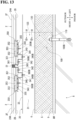
- first portion 110 and second portion 120 of the bracket 100 and the connection portion of the first portion 110 and the second portion 120 can be reinforced by the protruding portions 105 and 106 shown in FIGS. 5 to 7 .
- the heat insulating material 5 is arranged around the bracket 100, but the heights of the first and second side wall portions 101 and 102 can be kept small due to the protruding portions 105 and 106 taking on the role of increasing the rigidity. For this reason, on the sides of the brackets 100 on which the first and second side wall portions 101 and 102 are formed, it is possible to suppress the occurrence of gaps between the heat insulating material 5 and the brackets 100 using the first and second side wall portions 101 and 102.
- the first height H1 to which the protruding portions 105 and 106 protrude with respect to the mounting surface 126 is set to be less than or equal to the second height H2 to which the first side wall portion 101 and the second side wall portion 102 protrude with respect to the mounting surface 126. Accordingly, the second height H2 can be reduced according to the reinforcing effect of the bracket 100 by the protruding portions 105 and 106, and it is possible to suppress a case in which the first and second side wall portions 101 and 102 and the protruding portions 105 and 106 impede construction. Also, when the heat insulating material 5 is arranged around the bracket 100, it is possible to effectively suppress the occurrence of gaps between the heat insulating material 5 and the bracket 100 near the first and second side wall portions 101 and 102.
- the protruding portions 105 and 106 protrude only to the approximate center in the longitudinal direction of the second portion 120.
- the mounting surface 126 is flat in the range of the second portion 120 in which the protruding portions 105 and 106 are not present. Accordingly, the first joining portion 31 of the horizontal support body 30 can be reliably mounted on the mounting surface 126, and the mounting portion 125 and the first joining portion 31 can be reliably fastened to each other by the first drill screws 91.
- the outer wall board 2 has a so-called "four-way shiplap structure", an up-down shiplap portion is formed by the front-side up-down joining portion 23 and the back-side up-down joining portion 24 overlapping, and a left-right shiplap portion is formed by the front-side left-right joining portion 21 and the back-side left-right joining portion 22 overlapping. Accordingly, gaps between the outer wall boards 2 that are adjacent in the up-down direction and the left-right direction are not likely to occur. For this reason, the joining and waterproof property of the outer wall boards 2 can be ensured without using sealing or the like. Moreover, the quality of the appearance of the joining portions of the outer wall boards 2 also improves. Accordingly, it is possible to provide a high-quality wall structure for which construction is simple.
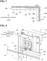
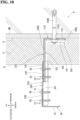
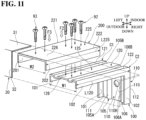
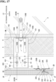
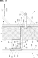
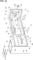
- FIGS. 10 to 12 with a wall structure of a second example, a case is indicated in which in the third step of the first example, the unevenness of the wall surface 9 is so significant that the unevenness of the wall surface 9 cannot be adjusted with the positioning of the first joining portion 31 of the horizontal support body 30 with respect to the mounting surface 126 of the bracket 100.
- an extension member 200 is arranged between the mounting portion 125 of the bracket 100 and the first joining portion 31 of the horizontal support body 30, whereby the significant unevenness is adjusted.
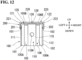
- the protruding portions 105 and 106 are extended until reaching the leading edge of the second portion 120.
- the mounting surface 126 is a flat surface divided into multiple surfaces in the width direction by the protruding portions 105 and 106.
- Other configurations of the second example are the same as those of the first example. For this reason, configurations identical to those of the first example will be denoted by reference numerals identical thereto, and description thereof will be omitted or simplified.
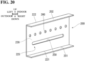
- the extension member 200 is manufactured due to a metal board material being subjected to bending or the like.
- the extension member 200 is formed into an approximate C shape in cross section due to a steel board material with a thickness of about 2 mm being subjected to bending or the like.
- the material and manufacturing method of the extension member 200 is not limited to those described above, and various materials and manufacturing methods can be selected as appropriate.
- extension member 200 In the following description of the shape of the extension member 200, as shown in FIG. 10 , the orientation of the extension member 200 in the state of being arranged between the mounting portion 125 of the bracket 100 and the first joining portion 31 of the horizontal support body 30 will be used as a reference.
- the extension member 200 includes an extension mounting portion 225, a first extension side wall portion 201, and a second extension side wall portion 202.
- the extension mounting portion 225 has an approximate rectangular shape.
- a length L225 in the indoor-outdoor direction of the extension mounting portion 225 is set to be approximately equal to the length L120 in the indoor-outdoor direction of the second portion 120, but the length L225 may also be longer or shorter than the length L120.
- the extension mounting portion 225 includes an extension mounting surface 226.
- the extension mounting surface 226 is the upper surface of the extension mounting portion 225.
- the first extension side wall portion 201 is formed continuously from one end to another end of the left side edge 221 of the extension mounting portion 225.
- the first extension side wall portion 201 protrudes downward from the left side edge 221 and extends in the indoor-outdoor direction.
- the second extension side wall portion 202 is formed similarly to the first extension side wall portion 201 on the right side edge 222 of the extension mounting portion 225.
- An inner width W2 of the first extension side wall portion 201 and the second extension side wall portion 202 of the extension member 200 is set to be slightly longer than an outer width W1 of the first side wall portion 101 and the second side wall portion 102 of the bracket 100.
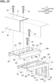
- the extension member 200 is arranged between the mounting portion 125 of the bracket 100 and the first joining portion 31 of the horizontal support body 30, the extension mounting portion 225 and the mounting portion 125 are fastened to each other by second drill screws 92, and the extension mounting portion 225 and the first joining portion 31 are fastened to each other by third drill screws 93.
- the second drill screw 92 and the third drill screw 93 are examples of fastening means.
- the configurations of the second drill screw 92 and the third drill screw 93 are the same as that of the first drill screw 91, and therefore description thereof is simplified.
- the task of arranging the extension member 200 between the mounting portion 125 and the first joining portion 31 is included in the above-described second step.
- the task of fastening the extension mounting portion 225 and the mounting portion 125 using the second drill screws 92 and the task of fastening the extension mounting portion 225 and the first joining portion 31 using the third drill screws 93 are included in the above-described third step.
- the extension member 200 is put in a state in which the extension mounting portion 225 is mounted on the mounting surface 126 of the bracket 100 and extends in the outdoor direction away from the first portion 110 of the bracket 100, and the extension mounting surface 226 faces the same side as the mounting surface 126. Accordingly, the first extension side wall portion 201 protrudes downward similarly to the first side wall portion 101 and is adjacent to the first side wall portion 101. Also, the second extension side wall portion 202 protrudes downward similarly to the second side wall portion 102 and is adjacent to the second side wall portion 102. At this time, unevenness in the wall surface 9 can be adjusted by shifting the position of the extension mounting portion 225 mounted on the mounting surface 126 in the indoor-outdoor direction.
- the second drill screws 92 perform pilot hole drilling, tapping, and fastening on the extension mounting portion 225 and the mounting portion 125.
- the second drill screw 92 penetrates through the mounting portion 125 and the extension mounting portion 225 in the up-down direction perpendicular to the mounting surface 126, and fastens the mounting portion 125 and the extension mounting portion 225.
- a configuration in which a pilot hole is drilled in advance at a location corresponding to the fastening location of the extension mounting portion 225 is also included in the present invention.
- the horizontal support body 30 is put in a state in which the first joining portion 31 is mounted on the extension mounting surface 226 of the extension member 200 and the second joining portion 32 is connected to the first joining portion 31 on a side opposite to the wall surface 9.
- the unevenness in the wall surface 9 can be adjusted also by shifting the position of the first joining portion 31 of the horizontal support body 30 mounted on the extension mounting surface 226 in the indoor-outdoor direction according to the protrusion or recession of the wall surface 9.
- the third drill screws 93 perform pilot hole drilling, tapping, and fastening on the extension mounting portion 225 and the first joining portion 31.
- the third drill screws 93 penetrate through the extension mounting portion 225 and the first joining portion 31 in the up-down direction perpendicular to the extension mounting surface 226 and fasten the extension mounting portion 225 and the first joining portion 31 to each other.
- the present invention also encompasses a configuration in which pilot holes are drilled in advance at positions corresponding to the fastening locations of the first joining portion 31.
- the bracket 100 and the horizontal support body 30 can be fastened to each other after the unevenness is adjusted using the extension member 200. Accordingly, it is possible to reliably realize a case in which the horizontal support body 30 is arranged straight in the left-right direction, and as a result, the outer wall boards 2 can be provided on the structural body 8 with high accuracy.
- construction is simple and fast, and the outer wall boards 2 can be stably supported.
- the extension member 200 even if a significant load F2 is applied to the extension member 200 when the second drill screws 92 fasten the mounting portion 125 and the extension mounting portion 225 to each other, the extension member 200, which is reinforced by the first and second extension side wall portions 201 and 202, can withstand the load F2. Also, even if a significant load F3 is applied to the extension member 200 when the third drill screws 93 fasten the extension mounting portion 225 and the first joining portion 31 to each other, the extension member 200 reinforced by the first and second extension side wall portions 201 and 202 can withstand the load F3. As a result, the unevenness in the wall surface 9 can be adjusted and the horizontal support body 30 can be fastened simply and strongly to the bracket 100 using the extension member 200 and the second and third drill screws 92 and 93.
- the left and right end portions of the outer wall boards 2 of the first example have been changed to flat side end surfaces without the front-side left-right joining portions 21 and the back-side left-right joining portions 22.
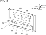
- the outer wall boards 2 are attached to the wall surface 9 using left-right joining portion support bodies 340, second attachment tools 350, and joiners 360, as shown in FIGS. 13 to 15 .
- Other configurations of the third example are the same as those of the first example. For this reason, configurations identical to those of the first example will be denoted by reference numerals identical thereto, and description thereof will be omitted or simplified.
- the left-right joining portion support bodies 340 are elongated board materials having an inverted hat-shaped cross-section.
- the left-right joining portion support bodies 340 include attachment board portions 341, first support board portions 342, and second support board portions 343.
- the first support board portion 342 is connected with a level difference to one side edge of the flat board-shaped attachment board portion 341 and extends in a flat board shape in the direction away from the attachment board portion 341.
- the second support board portion 343 is connected with a level difference to the other side edge of the flat board-shaped attachment board portion 341 and extends in a flat board shape in the direction away from the attachment board portion 341 and the first support board portion 342.
- the second support board portion 343 is wider than the first support board portion 342.
- the left-right joining portion support body 340 is an example of a second support body.
- the multiple left-right joining portion support bodies 340 are arranged on the wall surface 9 in a state of extending in the up-down direction on the outdoor side with respect to the second joining portion 32 of the horizontal support body 30, along the wall surface 9. Also, the left-right joining portion support bodies 340 are arranged at positions corresponding to the left end portion of the outer wall board 2 and positions corresponding to the right end portion of the outer wall board 2. Then, as shown in FIG. 13 , the attachment board portions 341 of the left-right joining portion support bodies 340 and the second joining portion 32 of the horizontal support body 30 are fastened to each other using screws 340B.
- the first support board portions 342 of the two left-right joining portion support bodies 340 located at the positions corresponding to the left end portion and the right end portion of the outer wall boards 2 are adjacent to each other.
- the joiner 360 is fastened to the first support board portions 342 by screws 360B.
- the joiner 360 is an elongated board material having a hat-shaped cross-section.
- the joiner 360 includes a protruding portion 361 that has an approximately C-shaped cross-section and protrudes in the outdoor direction.
- the second support board portion 343 of the left-right joining portion support body 340 located at the position corresponding to the left end portion of the outer wall board 2 is separated leftward from the joiner 360.
- the second support board portion 343 of the left-right joining portion support body 340 located at the position corresponding to the right end portion of the outer wall board 2 is separated rightward from the joiner 360.
- the second attachment tools 350 are fastened to the second support board portion 343 by the screws 350B.
- the second attachment tool 350 includes a second fixing portion 355, a second upper contact portion 356, a second lower contact portion 357, a second bearing portion 351, a second upper locking portion 352, and a second lower locking portion 353.
- the second fixing portion 355 forms a flat surface that can come into contact with the second support board portion 343 of the left-right joining portion support body 340.
- the second upper contact portion 356 bulges in the outdoor direction away from the second fixing portion 355.
- the second lower contact portion 357 bulges in the outdoor direction away from the second fixing portion 355 at a position below the second upper contact portion 356.
- the second bearing portion 351 protrudes in the outdoor direction from the second fixing portion 355 between the second upper contact portion 356 and the second lower contact portion 357 and extends in the left-right direction. Both end portions of the second upper contact portion 356 and both end portions of the second lower contact portion 357 are connected so as to surround the second bearing portion 351.
- the second upper locking portion 352 protrudes upward from the leading end portion of the second bearing portion 351.
- the second lower locking portion 353 protrudes downward from the leading end portion of the second bearing portion 351.
- the second attachment tool 350 has a configuration similar to that of the first attachment tool 50, except that the second attachment tool 350 does not have a portion equivalent to the standing piece 59 of the first attachment tool 50 according to the first example. For this reason, although description is simplified, as shown in FIG. 13 , the second attachment tool 350 supports the up-down shiplap portion of the outer wall boards 2 that are adjacent in the up-down direction, similarly to the first attachment tool 50.
- the protruding portion 361 of the joiner 360 is arranged between the mutually opposing side end surfaces of the outer wall boards 2 that are adjacent in the left-right direction of the outer wall board 2, and the space surrounded by the side end surfaces and the protruding portion 361 is filled with a sealing material S1.
- the protruding portion 361 of the joiner 360 also prevents horizontal shifting of the outer wall boards 2.
- each outer wall board 2 can be fixed, and therefore the construction is simple and fast, and the outer wall boards 2 can be stably supported.
- a wall structure of a fourth example multiple vertical support bodies 430 are arranged on the wall surface 9 in a state of being separated from each other at a predetermined interval in the left-right direction, and extending in the up-down direction along the wall surface 9.
- the vertical support bodies 430 are arranged extending across at least two brackets 100.
- the outer wall boards 2 are attached directly to the side of at least two vertical support bodies 430 that is opposite to the wall surface 9, and are arranged directly on the second joining portions 432 of the vertical support bodies 430.
- the vertical support body 430 is an example of a first support body.
- the first direction is the up-down direction.
- Other configurations of the fourth example are the same as those of the first example and the like. For this reason, configurations identical to those of the first example and the like will be denoted by reference numerals identical thereto, and description thereof will be omitted or simplified.
- the vertical support body 430 is an elongated molded material having a quadrangular tube-shaped cross-section.
- the vertical support body 430 is a rectangular steel pipe. Note that the material and manufacturing method of the vertical support body 430 are not limited to those described above, and various types of materials including resin, wood, and the like, and manufacturing methods can be selected as appropriate.
- the vertical support body 430 includes a first joining portion 431 and a second joining portion 432.
- the vertical support body 430 includes a pair of board-shaped portions that extend in the indoor-outdoor direction and the up-down direction, and the board-shaped portion located on the right among those board-shaped portions is a first joining portion 431.
- the vertical support body 430 includes a pair of board-shaped portions that extend in the left-right direction and the up-down direction, and the board-shaped portions located on the side opposite to the wall surface 9 among those board-shaped portions is a second joining portion 432. That is, the second joining portion 432 is connected to one edge of the flat board-shaped first joining portion 431 and extends in a flat board shape in a direction approximately orthogonal to the first joining portion 431.
- the orientation of the bracket 100 according to the first example is changed for use. That is, in the fourth example, the fixing portion 115 of the bracket 100 is fixed to the wall surface 9 in a state in which the mounting portion 125 of the bracket 100 extends in the indoor-outdoor direction and the up-down direction, and the mounting surface 126 is a leftward-facing plane.
- the round hole 110H according to example 1 is changed to an elongated hole 410H. Accordingly, the fixing portion 115 can be fixed to the wall surface 9 while adjusting the position of the bracket 100 in the left-right direction.
- a main elongated hole 150 and multiple main circular holes 160 are provided in the mounting portion 125.
- the bracket 100 according to the fourth example is an example of an attachment apparatus.
- the main elongated hole 150 extends in the outdoor direction away from the fixing portion 115.
- the longitudinal direction of the main elongated hole 150 is the indoor-outdoor direction.
- the main elongated hole 150 is arranged on an extended line of the rib 106B.
- the main circular holes 160 are arranged at positions separated from the main long hole 150 in a direction intersecting the longitudinal direction of the main long hole 150, that is, in the up-down direction.
- the main circular holes 160 are aligned in the indoor-outdoor direction.
- the main circular holes 160 are arranged on an extended line of the rib 105B.
- the construction method for the outer wall boards 2 of the fourth example is implemented through first to fourth steps.
- the multiple brackets 100 are arranged on the wall surface 9 by fixing the fixing portion 115 to the structural body 8 using an anchor bolt 100B in a state in which the mounting surface 126 is a leftward-facing plane.
- the multiple vertical support bodies 430 are put in a state of extending in the up-down direction along the wall surface 9 and being arranged extending across at least two brackets 100.
- the first joining portions 431 of the vertical support bodies 430 are mounted to the left of the mounting surfaces 126 of the brackets 100.
- the mounting portions 125 of the brackets 100 and the first joining portions 431 of the vertical support bodies 430 are fastened to each other by the first drill screws 91.
- the direction of fastening the first drill screws 91 has been changed to leftward in the fourth example.
- the vertical support body 430 can be temporarily fastened to the mounting portion 125 by inserting the first drill screw 91 into the main elongated hole 150 of the mounting portion 125 and then shallowly screwing the first drill screw 91 into the first joining portion 431. Also, in this state, the mounting portion 125 and the first joining portion 431 can be reliably fastened to each other by positioning the vertical support body 430 through shifting in the indoor-outdoor direction, and thereafter completely screwing the first drill screw 91 into the first joining portion 431. As a result, the positioning of the vertical support body 430 for adjusting unevenness of the wall surface 9 can be performed precisely and easily, and thus simplification of the task can be realized.
- the mounting portion 125 and the first joining portion 431 can be even more reliably fastened to each other by inserting another first drill screw 91 into a main circular hole 160 of the mounting portion 125 and screwing the other first drill screw 91 into the first joining portion 431.
- the other first drill screw 91 need not drill a pilot hole in the mounting portion 125, and therefore the fastening task performed by the other first drill screw 91 can be performed easily.
- the second attachment tool 350 according to the third example is fastened to the second joining portion 432 of the vertical support body 430 by the screw 350B, and the multiple outer wall boards 2 are attached by the second attachment tool 350 to the side of at least two vertical support bodies 430 that is opposite to the wall surface 9, and cover the wall surface 9.
- construction is simple and fast, and the outer wall boards 2 can be stably supported.
- a case is shown in which the unevenness of the wall surface 9 is so significant that the unevenness of the wall surface 9 cannot be adjusted with the positioning of the first joining portion 431 of the vertical support body 430 with respect to the mounting surface 126 of the bracket 100 in the third step according to the fourth example.
- the extension member 200 is arranged between the mounting portion 125 of the bracket 100 and the first joining portion 431 of the vertical support body 430 according to the fourth example, and thus the significant unevenness is adjusted.
- the orientation of the extension member 200 according to the second example is changed for use. That is, in the fifth example, the extension member 200 is mounted to the left of the mounting portion 125 in which the main elongated hole 150 and the main circular holes 160 are provided, in the bracket 100, in a state in which the extension mounting portion 225 extends in the indoor-outdoor direction and the up-down direction and the extension mounting surface 226 is a leftward-facing flat surface.
- an auxiliary elongated hole 250 and a plurality of auxiliary circular holes 260 are provided in the extension mounting portion 225.
- the bracket 100 and the extension member 200 according to the fifth example are examples of attachment apparatus according to the invention.
- the auxiliary elongated hole 250 extends in the outdoor direction away from the first portion 110 of the bracket 100.
- the longitudinal direction of the auxiliary elongated hole 250 is the indoor-outdoor direction.
- the auxiliary circular holes 260 are arranged at positions separated from the auxiliary elongated hole 250 in a direction intersecting the longitudinal direction of the auxiliary elongated hole 250, that is, in the up-down direction.
- the auxiliary circular holes 260 are aligned in the indoor-outdoor direction.
- the auxiliary elongated hole 250 and the auxiliary circular holes 260 are arranged at positions shifted downward with respect to the main elongated hole 150 of the mounting portion 125. Also, the auxiliary elongated hole 250 and the auxiliary circular holes 260 are arranged at positions shifted upward with respect to the main circular holes 160 of the mounting portion 125.
- the auxiliary elongated hole 250 and the auxiliary circular holes 260 are arranged at positions that do not overlap with the main elongated hole 150 of the mounting portion 125. Also, the auxiliary elongated hole 250 and the auxiliary circular holes 260 are arranged at positions that do not overlap with the main circular holes 160 of the mounting portion 125.
- the mounting portion 125 of the bracket 100 and the extension mounting portion 225 of the extension member 200 are fastened to each other by the second drill screws 92.
- the direction of fastening the second drill screws 92 has been changed to leftward in the fifth example.
- the extension member 200 can be temporarily fastened to the mounting portion 125 by inserting the second drill screw 92 into the main elongated hole 150 of the mounting portion 125 and shallowly screwing the second drill screw 92 into the extension mounting portion 225. Then, in this state, the mounting portion 125 and the extension mounting portion 225 can be reliably fastened to each other by positioning the extension member 200 through shifting in the indoor-outdoor direction and thereafter completely screwing the second drill screw 92 into the extension mounting portion 225.
- the mounting portion 125 and the extension mounting portion 225 can be even more reliably fastened to each other by inserting another second drill screw 92 into the main circular hole 160 of the mounting portion 125 and screwing the other second drill screw 92 into the extension mounting portion 225.
- the other second drill screw 92 need not drill a pilot hole in the mounting portion 125, and therefore the fastening task performed using the other second drill screw 92 can be performed easily.
- the extension mounting portion 225 of the extension member 200 and the first joining portion 431 of the vertical support body 430 are fastened to each other by the third drill screw 93.
- the direction of fastening the third drill screw 93 has also been changed to leftward.
- the vertical support body 430 is temporarily fastened to the extension mounting portion 225 by inserting the third drill screw 93 into the auxiliary elongated hole 250 of the extension mounting portion 225 and thereafter shallowly screwing the third drill screw 93 into the first joining portion 431. Then, in this state, the extension mounting portion 225 and the first joining portion 431 can be reliably fastened to each other by positioning the vertical support body 430 through shifting in the indoor-outdoor direction and thereafter completely screwing the third drill screw 93 into the first joining portion 431. As a result, the positioning of the vertical support body 430 for adjusting unevenness of the wall surface 9 can be performed efficiently and easily, and thus simplification of the task can be realized.
- the extension mounting portion 225 and the first joining portion 431 can be even more reliably fastened to each other by inserting another third drill screw 93 into the auxiliary circular hole 260 of the extension mounting portion 225 and screwing the other third drill screw 93 into the first joining portion 431.
- the other third drill screw 93 need not drill a pilot hole in the extension mounting portion 225, and therefore the fastening task performed using the other third drill screw 93 can be performed easily.
- the auxiliary elongated hole 250 and the auxiliary circular holes 260 are arranged at positions shifted with respect to the main elongated hole 150 of the mounting portion 125. Also, the auxiliary elongated hole 250 and the auxiliary circular holes 260 are arranged at positions shifted with respect to the main circular holes 160 of the mounting portion 125. Accordingly, the main elongated hole 150 and main circular holes 160, and the auxiliary elongated hole 250 and auxiliary circular holes 260 do not hinder each other's effects. As a result, the positioning of the vertical support body 430 for unevenness adjustment of the wall surface 9 can be performed even more efficiently and easily, and even greater simplification of the task can be realized.
- construction is simple and fast, and the outer wall boards 2 can be stably supported.
- the horizontal support body 30 of the first example is supported using the bracket 100 and the extension member 200 according to the fifth example.
- the first direction is the left-right direction.
- the orientations of the bracket 100 and the extension member 200 according to the fifth example are changed to be the same as the orientations of the bracket 100 and the extension member 200 according to the second example. That is, the extension mounting portion 225 of the extension member 200 is mounted on the mounting portion 125 of the bracket 100.
- the first joining portion 31 of the horizontal support body 30 is mounted on the extension mounting portion 225 of the extension member 200.
- the direction of fastening the second drill screws 92 and the direction of fastening the third drill screws 93 are downward.
- the mounting portion 125 of the bracket 100 and the extension mounting portion 225 of the extension member 200 that overlaps the mounting portion 125 from above are fastened to each other by the second drill screws 92.
- the extension member 200 can be temporarily fastened to the mounting portion 125 by inserting the second drill screw 92 into the auxiliary elongated hole 250 of the extension mounting portion 225 and thereafter shallowly screwing the second drill screw 92 into the mounting portion 125. Then, in this state, the mounting portion 125 and the extension mounting portion 225 can be reliably fastened to each other by positioning the extension member 200 through shifting in the indoor-outdoor direction and then completely screwing the second drill screw 92 into the mounting portion 125.
- the mounting portion 125 and the extension mounting portion 225 can be even more reliably fastened to each other by inserting another second drill screw 92 into an auxiliary circular hole 260 of the extension mounting portion 225 and screwing the other second drill screw 92 into the mounting portion 125.
- extension mounting portion 225 of the extension member 200 and the first joining portion 31 of the horizontal support body 30 that overlaps the extension mounting portion 225 from above are fastened to each other by the third drill screw 93 at a position that does not overlap with the auxiliary elongated hole 250 and the auxiliary circular holes 260 of the extension mounting portion 225.
- construction is simple and fast, and the outer wall boards 2 can be stably supported.
- Examples also encompasses a configuration in which the main elongated hole 150 and the main circular holes 160 have been removed from the bracket 100 of the modified example shown in FIG. 25 , although this is not shown in the drawings.
- the first direction is the left-right direction, but there is no limitation to this configuration, and the first direction may also be the up-down direction, as in the fourth and fifth embodiments. The same also applies to the second direction.
- first side wall portion 101 can be changed to a configuration in which the first side wall portion 101 extends continuously from a position shifted upward with respect to the lower end of the left side edge 111 of the first portion 110 to a position shifted toward the fixing portion 115 with respect to the leading end of the left side edge 121 of the second portion 120, and protrudes toward the narrow angle ⁇ 1 side.
- the second side wall portion 102 can be changed to a configuration in which the first side wall portion 101 extends continuously from a position shifted upward with respect to the lower end of the left side edge 111 of the first portion 110 to a position shifted toward the fixing portion 115 with respect to the leading end of the left side edge 121 of the second portion 120, and protrudes toward the narrow angle ⁇ 1 side.
- the present disclosure also encompasses a configuration in which the first attachment tool 50 according to the first example and the second attachment tool 350 according to the second example are not used, and the outer wall board 2 is fixed directly to the vertical support body 40 using a screw, a nail, or the like.
Landscapes
- Engineering & Computer Science (AREA)
- Architecture (AREA)
- Civil Engineering (AREA)
- Structural Engineering (AREA)
- Physics & Mathematics (AREA)
- Electromagnetism (AREA)
- Finishing Walls (AREA)
- Building Environments (AREA)
- Load-Bearing And Curtain Walls (AREA)
- Working Measures On Existing Buildindgs (AREA)
Description
- The present invention relates to a wall structure for a building.
-
Patent Documents 1 to 3 mentioned below disclose a conventional wall structure for a building. In the wall structure disclosed inPatent Document 1, multiple bracket base materials that extend in the left-right direction are arranged on a wall surface of a structural body. Multiple brackets are fixed to the bracket base materials. Also, multiple vertical furring strips that extend in the up-down direction along the wall surface are arranged extending across the multiple brackets. Furthermore, multiple board materials are attached to the vertical furring strips, and the board materials cover the wall surface. With this wall structure, when unevenness occurs in the wall surface, a countermeasure for preventing unevenness between the board materials attached to the structural body is needed. - In this respect, in the wall structure disclosed in
Patent Document 2, a bolt fixing hole is provided through a mounting portion of a base member, and an elongated hole is provided through a slide portion of a slide member. Then, when a male screw is inserted through the bolt fixing hole and the elongated hole and screwed into a slide member fixing nut, unevenness in the wall surface can be adjusted by shifting the slide portion with respect to the mounting portion. - Also, in the wall structure disclosed in
Patent Document 3, a bolt fixing hole is provided through a standing portion of a first bracket member, and an elongated hole is provided through a slide portion of a second bracket member. Then, when a bolt is inserted through the bolt fixing hole and the elongated hole and is screwed into a nut, unevenness of the wall surface can be adjusted by shifting the slide portion with respect to the standing portion. - Patent Document 4 discloses a mounting bracket for a facade substructure.
Patent Document 5 describes an attachment apparatus according to the preamble ofclaim 1, the attachment apparatus including a bracket and an extension member.Document 5 also discloses a wall structure and a method using such an attachment apparatus. -
- Patent Document 1:
JP 2002-339473A - Patent Document 2:
JP 2007-211511A - Patent Document 3:
JP 3137086U - Patent Document 4:
DE 85 01 840 U1 - Patent Document 5:
EP 0 008 272 A1 - However, with the wall structures disclosed in
Patent Documents - The present invention was made in view of the foregoing conventional circumstances, and a problem to be solved is to provide a wall structure for a building, an attachment apparatus, and a board material construction method, according to which construction is simple and fast, and board materials can be stably supported.
- The present invention provides an attachment apparatus according to appended
claim 1 and a wall structure for a building according to appendedclaim 2. - In the wall structure for a building according to the present invention, highly-rigid brackets each having first and second side wall portions that extend continuously from at least portions of both side edges of the first portion to at least portions of both side edges of the second portion are used. For this reason, unevenness in the wall surface of the structural body can be adjusted when the first joining portion of the first support body is mounted on the mounting surface, and the mounting portion of the bracket and the first joining portion of the first support body can be fastened to each other using the first drill screw at that position.
- That is, even if a significant load is applied to the bracket when the first drill screw fastens the mounting portion and the first joining portion to each other, the bracket reinforced by the first and second side wall portions can withstand the load. For this reason, with this wall structure, the unevenness adjustment of the wall surface and the arrangement of the first support body can be implemented in the same step, and therefore construction is simpler and faster.
- Also, with this wall structure, due to using a simple fastening configuration, looseness is not likely to occur between the bracket and the first support body. Furthermore, deformation caused by the bracket supporting the weight of the board material over a long period can be suppressed by the first and second side wall portions.
- Accordingly, with the wall structure for a building of the first aspect of the present invention, construction is simple and fast, and the board material can be stably supported.
- Here, the configuration in which "the board material is attached directly to the side of at least two of the first support bodies that is opposite to the wall surface, and the board material is arranged directly on the second joining portions of the first support bodies" specifically means a configuration in which the board material is arranged on the second joining portions without a support body other than the first support bodies being interposed, and the board material is attached directly to the first support bodies using a fastening member, an attachment tool, or the like, such as a screw. According to this configuration, by not using a support body other than the first support bodies to attach the board material, it is possible to realize a reduction of the number of parts and simplification of the task due to a reduction of the number of steps.
- On the other hand, the configuration in which "the board material is attached indirectly to the side of at least two first support bodies that is opposite to the wall surface and the board material is arranged indirectly on the second joining portions of the first support bodies" specifically means a configuration in which the board material is arranged on the second joining portions with a support body other than the first support bodies interposed, the other support body is attached to the first support bodies using a fastening member such as a screw, and furthermore, the board material is attached to the other support body using a fastening member such as a screw, an attachment tool, or the like. There is at least one other support body. According to this configuration, by using the support body other than the first support bodies, the unevenness adjustment of the wall surface can be implemented even more preferably and the board material can be supported even more stably.
- It is desirable that the wall structure for a building includes a plurality of second support bodies that extend in a second direction intersecting the first support bodies along the wall surface and are arranged extending across at least two of the first support bodies. It is desirable that the second support bodies are arranged on the second joining portions. Also, it is desirable that the board materials are attached to at least two of the second support bodies.
- In this case, using the first support body and the second support body, which intersect each other, the unevenness adjustment of the wall surface can be implemented even more preferably, and the board material can be supported even more stably.
- The brackets each include a protruding portion that is provided between the first side wall portion and the second side wall portion, extends continuously from at least a portion of the first portion to at least a portion of the second portion, and protrudes toward the narrow angle side.
- In this case, the first portion and second portion of the bracket and the connection portions of the first portion and second portion can be reinforced by the protruding portion. For this reason, the protrusion lengths of the first side wall portion and the second side wall portion can be suppressed to be small. Accordingly, if the heat insulating material is arranged around the bracket, it is possible to suppress a case in which a gap occurs between the narrow angle side of the second portion of the bracket and the heat insulating material using the first side wall portion and the second side wall portion.
- The protruding portion extends to the approximate center of the second portion. The mounting surface is a flat surface formed in a range of the second portion that is farther from the first portion than the protruding portion.
- In this case, the mounting surface is a flat surface due to being formed in a range of the second portion in which the protruding portion does not exist, and therefore the first joining portion of the first support body can be reliably mounted on the mounting surface, and the mounting portion and the first joining portion can be reliably fastened to each other using the first drill screw.
- A first height to which the protrusion portion protrudes with respect to the mounting surface is set to be less than or equal to a second height to which the first side wall portion and the second side wall portion protrude with respect to the mounting surface.
- In this case, due to the first height being set to be less than or equal to the second height, the second height can be reduced according to the reinforcing effect of the protruding portion on the bracket, and it is possible to suppress a case in which the first and second side wall portions and the protruding portion hinder construction. Also, if the heat insulating material is arranged around the bracket, it is possible to effectively suppress a case in which a gap occurs between the heat insulating material and the bracket near the first and second side wall portion on the narrow angle side of the second portion of the bracket.
- The mounting portion is provided with a main elongated hole that extends away from the fixing portion.
- In this case, when the mounting portion of the bracket and the first joining portion of the first support body are to be fastened to each other, the first support body can be temporarily fastened to the mounting portion by inserting the first drill screw into the main elongated hole of the mounting portion and thereafter shallowly screwing the first drill screw into the first joining portion. Then, in this state, the mounting portion and the first joining portion can be reliably fastened to each other by positioning the first support body through shifting in a direction of moving away from the fixing portion or the opposite direction, and thereafter completely screwing the first drill screw into the first joining portion. As a result, the positioning of the first support body for adjusting the unevenness of the wall surface can be performed precisely and easily, and thus simplification of the task can be realized.
- The mounting portion is provided with at least one main circular hole arranged at a position away from the main elongated hole in a direction intersecting a longitudinal direction of the main elongated hole.
- In this case, the first drill screw is inserted into the main elongated hole of the mounting portion and positioning adjustment of the first support body is performed, and the mounting portion and the first joining portion are reliably fastened to each other, and thereafter the mounting portion and the first joining portion can be even more reliably fastened to each other by inserting another first drill screw into the main circular hole of the mounting portion and screwing the other first drill screw into the first joining portion. At this time, the other first drill screw need not drill a pilot hole in the mounting portion, and therefore the task of fastening using the other first drill screw can be performed easily.
- The wall structure for a building includes an extension member configured to be arranged between the mounting portion of the bracket and the first joining portion of the first support body. The extension member includes: an extension mounting portion that is configured to be mounted on the mounting surface, extends away from the first portion, and includes an extension mounting surface that faces the same side as the mounting surface such that the first joining portion is mounted thereon; a first extension side wall portion that protrudes in the same direction as the first side wall portion from one side edge of the extension mounting portion, and is adjacent to the first side wall portion; and a second extension side wall portion that protrudes in the same direction as the second side wall portion from another side edge of the extension mounting portion, and is adjacent to the second side wall portion. The fastening members include: a second drill screw for fastening the mounting portion and the extension mounting portion to each other in a direction perpendicular to the mounting surface; and a third drill screw for fastening the extension mounting portion and the first joining portion to each other in a direction perpendicular to the extension mounting surface.
- In this case, even if unevenness in the wall surface is significant, the unevenness is adjusted using the extension member, and then the bracket and the first support body can be fastened to each other. Accordingly, it is possible to reliably realize a case in which the first support body is arranged straight in a first direction, and as a result, the board material can be arranged on the structural body with high accuracy. Also, due to the first and second extension side wall portions sandwiching the first and second side wall portions, horizontal shifting of the extension member with respect to the mounting portion can be suppressed when the extension member slides in the direction toward or away from the wall surface, and when the second drill screw fastens the mounting portion and the extension mounting portion to each other. Furthermore, even if a significant load acts on the extension member when the second drill screw fastens the mounting portion and the extension mounting portion to each other, the extension member reinforced by the first and second extension side wall portions can withstand the load. Also, even if a significant load acts on the extension member when the third drill screw fastens the extension mounting portion and the first joining portion to each other, the extension member reinforced by the first and second extension side wall portions can withstand the load. As a result, unevenness in the wall surface can be adjusted and the first support body can be easily and strongly fastened to the bracket using the extension member and the second and third drill screws.
- It is desirable that the extension mounting portion is provided with an auxiliary elongated hole that extends away from the first portion.
- In this case, when the extension mounting portion of the extension member and the first joining portion of the first support body are fastened to each other, the first support body can be temporarily fastened to the extension mounting portion by inserting the third drill screw into the auxiliary elongated hole of the extension mounting portion and thereafter shallowly screwing the third drill screw into the first joining portion. Then, in that state, the extension mounting portion and the first joining portion can be reliably fastened to each other by positioning the first support body through shifting in the direction of moving away from the first portion or the opposite direction and thereafter completely screwing the third drill screw into the first joining portion. As a result, the positioning of the first support body for adjusting the unevenness of the wall surface can be performed precisely and easily, and thus simplification of the task can be realized.
- The extension mounting portion is provided with at least one auxiliary circular hole arranged at a position away from the auxiliary elongated hole in a direction intersecting the longitudinal direction of the auxiliary elongated hole.
- In this case, the third drill screw is inserted into the auxiliary elongated hole of the extension mounting portion, and positioning adjustment of the first support body is performed, whereupon the extension mounting portion and the first joining portion are reliably fastened to each other, and thereafter the extension mounting portion and the first joining portion can be even more reliably fastened to each other by inserting another third drill screw into the auxiliary circular hole of the extension mounting portion and screwing the other third drill screw into the first joining portion. At this time, the other third drill screw need not drill a pilot hole in the extension mounting portion, and therefore the task of fastening using the other third drill screw can be performed easily.
- The auxiliary elongated hole and the auxiliary circular hole are arranged at positions shifted with respect to the main elongated hole. The auxiliary elongated hole and the auxiliary circular hole are arranged at positions shifted with respect to the main circular hole.
- In this case, when the mounting portion of the bracket and the extension mounting portion of the extension member are fastened to each other, the extension member can be temporarily fastened to the mounting portion by inserting the second drill screw into the main elongated hole of the mounting portion and thereafter shallowly screwing the second drill screw into the extension mounting portion. Then, in this state, the mounting portion and the extension mounting portion can be reliably fastened to each other by positioning the extension member through shifting in the direction of moving away from the first portion or the opposite direction and thereafter completely screwing the second drill screw into the extension mounting portion. Thereafter, the mounting portion and the extension mounting portion can be even more reliably fastened to each other by inserting another second drill screw into the main circular hole of the mounting portion and screwing the other second drill screw into the extension mounting portion. At this time, the other second drill screw need not drill a pilot hole in the mounting portion, and therefore the task of fastening using the other second drill screw can be performed easily. The task of fastening with the third drill screw, using the auxiliary elongated hole and the auxiliary circular hole, is as described in the ninth and tenth aspects of the present invention. At this time, the auxiliary elongated hole and the auxiliary circular hole are arranged at positions shifted with respect to the main elongated hole, and the auxiliary elongated hole and the auxiliary circular hole are arranged at positions shifted with respect to the main circular hole, whereby the auxiliary elongated hole and the auxiliary circular hole do not hinder each other's effect. As a result, the positioning of the first support body for adjusting the unevenness of the wall surface can be performed even more precisely and easily, and thus further simplification of the task can be realized.
- Also, in this case, when the first support body extends horizontally, that is, when the first direction is the horizontal direction, the following work procedure can also be used, with consideration given to ease of performing the task. That is, when the mounting portion of the bracket and the extension mounting portion of the extension member, which overlaps the mounting portion from above, are to be fastened to each other, the extension member can be temporarily fastened to the mounting portion by inserting the second drill screw into the auxiliary elongated hole of the extension mounting portion and thereafter shallowly screwing the second drill screw into the mounting portion. Then, in this state, the mounting portion and the extension mounting portion can be reliably fastened to each other by positioning the extension member through shifting in the direction of moving away from the first portion or the opposite direction and thereafter completely screwing the second drill screw into the mounting portion. Thereafter, the mounting portion and the extension mounting portion can be even more reliably fastened to each other by inserting another second drill screw into the auxiliary circular hole of the extension mounting portion and screwing the second drill screw into the mounting portion.
- It is desirable that the board materials each have a quadrilateral shape with four first to fourth end portions. It is desirable that in each of the board materials, the first end portion of the board material includes a first shiplap joining portion that is recessed from a back surface to a front surface of the board material and extends along the first end portion. It is desirable that the second end portion of the board material opposing the first end portion includes a second shiplap joining portion that is recessed from the front surface to the back surface of the board material and extends along the second end portion . It is desirable that the third end portion that intersects the first end portion and the second end portion of the board material includes a third shiplap joining portion that is recessed from the front surface to the back surface of the board material and extends along the third end portion. Also, it is desirable that the fourth end portion of the board material that opposes the third end portion includes a fourth shiplap joining portion that is recessed from the back surface to the front surface of the board material and extends along the fourth end portion.
- In this case, the board material has a so-called "four-way shiplap structure", and a joining portion in one direction, such as a joining portion in vertical direction, is formed due to the first shiplap joining portion and the second shiplap joining portion overlapping. Also, a joining portion in another direction, such as a joining portion in a horizontal direction, is formed due to the third shiplap joining portion and the fourth shiplap joining portion overlapping. Accordingly, gaps between board materials that are adjacent in the vertical direction and the horizontal direction are not likely to occur. For this reason, the joining and waterproof property of the board materials can be ensured without using sealing or the like. Also, the quality of the appearance of the joining portions of the board materials is improved. Accordingly, it is possible to provide a high-quality wall structure for which construction is simple.
- The invention further provides an attachment apparatus according to appended
claim 1. - According to the attachment apparatus of the present invention, it is possible to exhibit effects similar to those of the wall structure for a building of the present invention.
- The bracket includes a protrusion portion that is provided between the first side wall portion and the second side wall portion, extends continuously from at least a portion of the first portion to at least a portion of the second portion, and protrudes toward the narrow angle side.
- In this case, it is possible to exhibit an effect similar to that of the wall structure for a building of the third aspect of the present invention.
- The attachment apparatus includes an extension member configured to be used along with the bracket. The extension member includes: an extension mounting portion that includes an extension mounting surface and is to be mounted on the mounting surface; a first extension side wall portion that protrudes from one side edge of the extension mounting portion; and a second extension side wall portion that protrudes from another side edge of the extension mounting portion. The extension mounting portion is provided with an auxiliary elongated hole that extends in the longitudinal direction of the extension mounting surface, and at least one auxiliary circular hole that is arranged at a position away from the auxiliary elongated hole in a direction intersecting the longitudinal direction of the auxiliary elongated hole. When the extension mounting portion of the extension member is mounted on the mounting surface of the bracket, the extension mounting surface faces the same side as the mounting surface, the first extension side wall portion is adjacent to the first side wall portion, and the second extension side wall portion is adjacent to the second side wall portion, the auxiliary elongated hole and the auxiliary circular hole are arranged at positions shifted with respect to the main elongated hole, and the auxiliary elongated hole and the auxiliary circular hole are arranged at positions shifted with respect to the main circular hole.
- In this case, it is possible to exhibit an effect similar to that of the wall structure for a building of the eighth to eleventh aspects of the present invention.
- The invention further provides a board material construction method according to appended
claim 6. - According to the board material construction method of the present invention, similarly to the wall structure for a building according to the present invention, construction is simple and fast, and the board material can be stably supported.
- It is desirable that the fourth step includes: a fifth step of arranging a plurality of second support bodies in a manner extending across at least two of the first support bodies, the plurality of second support bodies extending in a second direction intersecting the first support bodies along the wall surface; and a sixth step of attaching the board materials to at least two of the second support bodies. Also, it is desirable that in the fifth step, the second support bodies are arranged on the second joining portions of the first support bodies.
- In this case, it is possible to exhibit an effect similar to that of the wall structure for a building of the second aspect of the present invention.
- The mounting portion is provided with a main elongated hole that extends away from the fixing portion. It is desirable that in the third step, the first drill screw is inserted into the main elongated hole and thereafter is shallowly screwed into the first joining portion, then the first support body is positioned through shifting in a direction of moving away from the fixing portion or the opposite direction, and then the first drill screw is completely screwed into the first joining portion.
- In this case, it is possible to exhibit an effect similar to that of the wall structure for a building of the sixth aspect of the present invention.
- In the second step, an extension member is arranged between the mounting portion of the bracket and the first joining portion of the first support body. The extension member includes: an extension mounting portion that is configured to be mounted on the mounting surface, extends away from the first portion, and includes an extension mounting surface that faces the same side as the mounting surface and on which the first joining portion is to be mounted; a first extension side wall portion that protrudes in the same direction as the first side wall portion from one side edge of the extension mounting portion, and is adjacent to the first side wall portion; and a second extension side wall portion that protrudes in the same direction as the second side wall portion from another side edge of the extension mounting portion, and is adjacent to the second side wall portion. It is desirable that in the third step, the fastening member fastens the mounting portion and the extension mounting portion to each other in a direction perpendicular to the mounting surface using a second drill screw, and the fastening member fastens the extension mounting portion and the first joining portion to each other in a direction perpendicular to the extension mounting surface using a third drill screw.
- In this case, similarly to the wall structure for a building according to the eighth aspect of the present invention, unevenness of the wall surface can be adjusted and the first support body can be easily and strongly fastened to the bracket using the extension member and the second and third drill screws.
- It is desirable that the extension mounting portion is provided with an auxiliary elongated hole that extends away from the first portion. Also, it is desirable that in the third step, the third drill screw is inserted into the auxiliary elongated hole and thereafter shallowly screwed into the first joining portion, then the first support body is positioned through shifting in the direction of moving away from the first portion or the opposite direction, and then the third drill screw is completely screwed into the first joining portion.
- In this case, it is possible to exhibit an effect similar to that of the wall structure for a building of the present invention.
- With the wall structure for a building, the attachment apparatus, and the construction method for board materials of the present invention, construction is simple and fast, and board materials can be stably supported.
-
-
FIG. 1 is a perspective view of a wall structure for a building of a first embodiment. -
FIG. 2 is a perspective view of an outer wall board of the first example. -
FIG. 3 is a partial perspective view according to the first example. -
FIG. 4 is a partial cross-sectional view of the wall structure of the first example. -
FIG. 5 is a perspective view according to the first example. -
FIG. 6 is a front view of a bracket according to the first example. -
FIG. 7 is a cross-sectional view showing a cross-section taken along VII-VII inFIG. 6 . -
FIG. 8 is a partial perspective view according to the first example. -
FIG. 9 is a perspective view of a first attachment tool according to the first example. -
FIG. 10 is a partial cross-sectional view of a wall structure of a second example. -
FIG. 11 is a perspective view according to the second example. -
FIG. 12 is a front view according to the second example. -
FIG. 13 is a partial cross-sectional view of a wall structure of a third example. -
FIG. 14 is a partial perspective view according to the third example. -
FIG. 15 is a perspective view of a second attachment tool according to the third example. -
FIG. 16 is a perspective view of a wall structure for a building of a fourth example. -
FIG. 17 is a partial cross-sectional view of the wall structure of the fourth example. -
FIG. 18 is a cross-sectional view showing a cross-section taken along XVIII-XVIII inFIG. 17 . -
FIG. 19 is a perspective view of a bracket and a first support body according to the fourth example. -
FIG. 20 is a perspective view of an extension member according to a fifth example. -
FIG. 21 is a partial cross-sectional view of a wall structure of the fifth example. -
FIG. 22 is a perspective view of a bracket, the extension member, and a first support body according to the fifth example. -
FIG. 23 is a perspective view of a bracket, an extension member, and a first support body according to a sixth example in conformity with the invention. -
FIG. 24 is a perspective view of the bracket, the extension member, and the first support body according to the sixth example. -
FIG. 25 is a perspective view showing a modified example of a bracket. - Hereinafter, first to sixth examples for understanding the present invention will be described with reference to the drawings. Note that in
FIG. 1 , a vertical upward direction is upward, and a vertical downward direction is downward. Also, in a direction from outside to inside the room inFIG. 1 , a horizontal leftward direction is leftward, and a horizontal rightward direction is rightward. Also, the directions shown inFIG. 2 and onward correspond to those inFIG. 1 . - As shown in
FIG. 1 , a wall structure of a first example is an example of a specific form of a wall structure for a building. The wall structure is obtained by attaching multipleouter wall boards 2 to astructural body 8 included in a building such as a residence, a facility, or a warehouse. Thestructural body 8 may also be included in a newly-built building, or may be included in an already-built building to be subjected to construction work for reforming the building exterior. Theouter wall boards 2 are an example of board materials. As shown inFIG. 2 ,FIG. 3 , and the like, theouter wall boards 2 are board materials that have high strength and rigidity and that form an outer wall of a building. Theouter wall boards 2 may also be used in a newly-built building, or may be for reforming for improving design by covering a wall surface of an already-built building. Note that the board material is not limited to an outer wall board, and for example, may also be a decorative board for covering the exterior of a building, a structure panel for indoor use, an interior board, or the like. - As shown in
FIG. 1 , thestructural body 8 is a strong frame made of reinforced concrete or bricks, andmortar 8M is applied to the outermost layer on an outdoor side of the frame. Thestructural body 8 has awall surface 9 that faces an outdoor direction. Note that the structural body is not limited to the present embodiment, and for example, themortar 8M of thestructural body 8 is omitted in some cases. Also, the structural body may also be included in a wooden building built using wood post and beam construction, timber frame construction, or the like. -
Brackets 100, aheat insulating material 5,waterproof sheets 6,horizontal support bodies 30,vertical support bodies 40, andfirst attachment tools 50 are arranged between thestructural body 8 and theouter wall boards 2. Thehorizontal support bodies 30 are an example of first support bodies. Thevertical support bodies 40 are an example of second support bodies. - As shown in
FIGS. 1 and4 ,multiple brackets 100 are arranged on thewall surface 9, separated from each other by predetermined intervals in the up-down direction and the left-right direction. Thespacers 3 shown inFIG. 1 are arranged as needed between thebrackets 100 and thewall surface 9. Thespacers 3 are approximately rectangular boards with U-shaped grooves cut out. Due to thespacers 3 being made of resin, it is possible to block heat bridges between thebrackets 100 and thewall surface 9. Also, by selecting the thickness and number of thespacers 3 according to the unevenness of thewall surface 9, the unevenness of thewall surface 9 can be adjusted to a certain extent. - As shown in
FIGS. 5 to 7 , thebracket 100 is manufactured due to a metal board material being subjected to bending, pressing, and the like. To give an example, regarding thebracket 100, a steel board material with a thickness of about 2 mm is subjected to bending, pressing, and the like, and is formed into a three-dimensional shape without performing partial welding. Note that the material and manufacturing method of thebracket 100 is not limited to those described above, and various materials and manufacturing methods can be selected as appropriate. Also, during machining of thebracket 100, abutting end portions of two separately-bent protruding pieces are welded together, whereby the protruding pieces can be made continuous. - In the following description of the shape of the
bracket 100, the up-down direction, the left-right direction, and the indoor-outdoor direction are defined with reference to the orientation of thebrackets 100 in the state of being arranged on thewall surface 9, as shown inFIG. 4 and the like. - As shown in
FIGS. 5 to 7 , thebracket 100 includes afirst portion 110, asecond portion 120, a firstside wall portion 101, a secondside wall portion 102, protrudingportions portion 125. - The
first portion 110 is approximately square-shaped, and acircular hole 110H is provided through the approximate center thereof. Thefirst portion 110 includes a fixingportion 115. The fixingportion 115 forms a flat surface that surrounds thecircular hole 110H. As shown inFIG. 4 , the fixingportion 115 is brought into contact with thewall surface 9 in a state of extending in the up-down direction and the left-right direction, ananchor bolt 100B is inserted through thecircular hole 110H, and theanchor bolt 100B is further fastened to theside wall 9. Accordingly, the fixingportion 115 is fixed to theside wall 9. - As shown in
FIG. 5 , thesecond portion 120 is approximately rectangular and is connected to the upper edge of thefirst portion 110. Thesecond portion 120 is bent from thefirst portion 110 in the outdoor direction and extends away from the fixingportion 115. The narrow angle of the angle formed by thefirst portion 110 and thesecond portion 120 is α1. The narrow angle α1 is set to be an approximate right angle. - As shown in
FIG. 7 , a length L120 in the indoor-outdoor direction of thesecond portion 120 is set to be approximately twice a length L110 in the up-down direction of thefirst portion 110 for example, but there is no limitation to this configuration, and the length L120 may be greater or less than this length. For example, the length L120 can also be set to be equal to the length L110. - As shown in
FIGS. 5 to 7 , the firstside wall portion 101 is approximately L-shaped due to connection between a board-shaped portion that is connected to the entireleft side edge 111 of thefirst portion 110 and is bent at an approximate right angle in the outdoor direction, and a board-shaped portion that is connected to the entireleft side edge 121 of thesecond portion 120 and is bent at an approximate right angle downward. That is, the firstside wall portion 101 extends continuously from the lower end of theleft side edge 111 of thefirst portion 110 to the leading end of theleft side edge 121 of thesecond portion 120 and protrudes to the narrow angle α1 side. - The second
side wall portion 102 is approximately L-shaped due to connection between a board-shaped portion that is connected to the entireright side edge 112 of thefirst portion 110 and is bent at an approximate right angle in the outdoor direction, and a board-shaped portion that is connected to the entireright side edge 122 of thesecond portion 120 and is bent at an approximate right angle downward. That is, the secondside wall portion 102 extends continuously from the lower end of theright side edge 112 of thefirst portion 110 to the leading end of theright side edge 122 of thesecond portion 120 and protrudes to the narrow angle α1 side. - As shown in
FIG. 5 , a corner portion C1 formed by thefirst portion 110, thesecond portion 120, and the firstside wall portion 101 is formed seamlessly through pressing. A corner portion C2 formed by thefirst portion 110, thesecond portion 120, and the secondside wall portion 102 is also formed seamlessly through pressing. - As shown in
FIGS. 5 to 7 , in thefirst portion 110, arib 105A that has a U-shaped cross-section is formed so as to protrude in the outdoor direction between the firstside wall portion 101 and thecircular hole 110H and extend in the up-down direction. In thesecond portion 120, arib 105B that has a U-shaped cross-section and connects to therib 105A is formed so as to protrude downward and extend in the indoor-outdoor direction. The protrudingportion 105 on the left is formed by theribs - In the
first portion 110, arib 106A that has a U-shaped cross-section is formed so as to protrude in the outdoor direction between the secondside wall portion 102 and thecircular hole 110H and extend in the up-down direction. In thesecond portion 120, arib 106B that has a U-shaped cross-section and connects to therib 106A is formed so as to protrude downward and extend in the indoor-outdoor direction. The protrudingportion 106 on the right is formed by theribs - The protruding
portions first portion 110, are bent in the outdoor direction at the upper edge of thefirst portion 110, extend in the outdoor direction, and end at the approximate center of thesecond portion 120. - That is, the protruding
portions side wall portion 101 and the secondside wall portion 102, extend continuously from the lower edge of thefirst portion 110 to the approximate center of thesecond portion 120, and protrude to the narrow angle α1 side. - The mounting
portion 125 is provided on the leading edge side of thesecond portion 120. The mountingportion 125 includes a mountingsurface 126. The mountingsurface 126 is a flat surface that is surrounded by the leading edge of thesecond portion 120, the left-side edge 121, the right-side edge 122, and the leading ends of the protrudingportions side wall portion 101 and the secondside wall portion 102. That is, the mountingsurface 126 is an upward-facing flat surface formed in a range of thesecond portion 120 that is farther from thefirst portion 110 than the leading ends of the protrudingportions - As shown in
FIG. 6 , a first height H1 to which the protrudingportions surface 126 is set to be less than or equal to a second height H2 to which the firstside wall portion 101 and the secondside wall portion 102 protrude downward with respect to the mountingsurface 126. - As shown in
FIGS. 1 and4 , theheat insulating material 5 is arranged along thewall surface 9 of thestructural body 8. Theheat insulating material 5 is, for example, a fibrous heat insulating material such as rock wool or glass wool, a plastic foam-type heat insulating material such as polyurethane foam, phenol foam, or polystyrene foam, or the like. Theheat insulating material 5 is arranged such that portions that interfere with thebrackets 100 are removed and the leading edge sides of the mountingportions 125 of thebrackets 100 are exposed. Note that theheat insulating material 5 can also be omitted, depending on the construction state or the like of thestructural body 8. - The
waterproof sheets 6 are laid on the front surface of theheat insulating material 5. Thewaterproof sheets 6 are composed of waterproof paper, film, nonwoven fabric, or the like, and some are moisture-permeable instead of being waterproof. Note that thewaterproof sheets 6 can also be omitted, depending on the construction state or the like of thestructural body 8. Notches are formed in thewaterproof sheets 6 at locations corresponding to thesecond portions 120 of thebrackets 100, and thewaterproof sheets 6 are arranged so as to cause the leading edge sides of the mountingportions 125 of thebrackets 100 to protrude. - As shown in
FIGS. 4 and5 , thehorizontal support body 30 is an elongated board material having an L-shaped cross-section. Thehorizontal support body 30 includes a first joiningportion 31 and a second joiningportion 32. The second joiningportion 32 connects to one edge of the flat board-shaped first joiningportion 31, and extends in a flat board shape in a direction approximately orthogonal to the first joiningportion 31. Thehorizontal support body 30 is manufactured by performing bending and the like on a steel board material, for example. Note that the material and manufacturing method of thehorizontal support body 30 are not limited to those described above, and various types of materials including resin, wood, and the like, and manufacturing methods can be selected as appropriate. - As shown in
FIG. 1 , the multiplehorizontal support bodies 30 are arranged on thewall surface 9 in a state of being separated from each other at a predetermined interval in the up-down direction on the outdoor side with respect to thewaterproof sheets 6, and extending in the left-right direction along thewall surface 9. Ahorizontal support body 30 is arranged extending across at least twobrackets 100. As shown inFIGS. 4 and5 , thebracket 100 and thehorizontal support body 30 are fastened to each other by first drill screws 91. The left-right direction is an example of a first direction. The first drill screws 91 are an example of fastening members. - More specifically, the
horizontal support bodies 30 are put in a state in which the first joiningportions 31 are mounted on the mountingsurfaces 126 of thebrackets 100 and the second joiningportions 32 are located on the side opposite to thewall surface 9 with respect to the first joiningportions 31. - A known drill screw, in which a drill such as a cutting blade portion or a tapered portion is formed at the leading end of a screw, and which performs pilot hole drilling, tapping, and fastening with the screw itself, is used as the
first drill screw 91. Specifically, thefirst drill screw 91 includes ascrew portion 91B, acutting blade portion 91C formed on the leading end of thescrew portion 91B, and ahead portion 91A that connects to the base of thescrew portion 91B. - First, unevenness in the
wall surface 9 is adjusted by shifting the position of the first joiningportion 31 of thehorizontal support body 30 mounted on the mountingsurface 126 in the indoor-outdoor direction according to the protrusion and recession of thewall surface 9 of thestructural body 8. Then, thefirst drill screw 91 is held in an electric screwdriver (not shown) by fitting the leading end portion of the electric screwdriver (not shown) into a groove provided in thehead portion 91A of thefirst drill screw 91. Next, thecutting blade portion 91C of thefirst drill screw 91 is brought into contact with the first joiningportion 31 from above, and the fastening position is determined. Then, the electric screwdriver (not shown) is operated while causing a downward load F1 to act on thefirst drill screw 91. Upon doing so, thecutting blade portion 91C rotates while being pressed into the first joiningportion 31 and the mountingportion 125, and thereby cuts the first joiningportion 31 and the mountingportion 125 while discharging cutting debris and drills pilot holes in the first joiningportion 31 and the mountingportion 125. Thescrew portion 91B performs tapping using a portion adjacent to thecutting blade portion 91C and performs fastening on the first joiningportion 31 and the mountingportion 125 using a portion located on thehead portion 91A side with respect to the portion adjacent to thecutting blade portion 91C. The downward load F1 reaches its maximum when thecutting blade portion 91C opens a pilot hole in the first joiningportion 31 and the mountingportion 125. - In this manner, the
first drill screw 91 penetrates through the mountingportion 125 and the first joiningportion 31 in the up-down direction, which is perpendicular to the mountingsurface 126, and fastens the mountingportion 125 and the first joiningportion 31 to each other. Note that the present invention also encompasses a configuration in which a pilot hole is drilled in advance at a position corresponding to the fastening location of the first joiningportion 31. - As shown in
FIGS. 4 and8 , thevertical support body 40 is an elongated board material having a hat-shaped cross-section. Thevertical support body 40 includes acentral board portion 41 and a pair ofside board portions 42. The pair ofside board portions 42 are connected with a level difference to both side edges of the flat board-shaped central board portion, and extend in flat board shapes in the direction away from each other. Thevertical support body 40 is manufactured by performing bending and the like on a steel board material, for example. Note that the material and manufacturing method of thevertical support body 40 are not limited to those described above, and various types of materials including resin, wood, and the like, and manufacturing methods can be selected as appropriate. - As shown in
FIG. 1 , the multiplevertical support bodies 40 are arranged on thewall surface 9 in a state of being separated from each other by a predetermined interval in the left-right direction on the outdoor side with respect to the second joiningportions 32 of thehorizontal support bodies 30, and extending in the up-down direction along thewall surface 9. Thevertical support bodies 40 are each arranged extending across at least twohorizontal support bodies 30. Also, as shown inFIGS. 4 and8 , the pair ofside board portions 42 of thevertical support body 40 and the second joiningportion 32 of thehorizontal support body 30 are fastened to each other by thescrew 40B. The up-down direction is an example of a second direction. - The
screws 40B shown inFIG. 4 are also drill screws. If drill screws are not used, a task of drilling pilot holes in theside board portion 42 and the second joiningportion 32 is needed before the task of fastening the pair ofside board portions 42 of thevertical support body 40 and the second joiningportion 32 of thehorizontal support body 30 to each other using thescrews 40B. - As shown in
FIG. 9 , thefirst attachment tool 50 includes a first fixingportion 55, a firstupper contact portion 56, a firstlower contact portion 57, afirst bearing portion 51, firstupper locking portions 52, a firstlower locking portion 53, and a standingpiece 59. Thefirst fixing portion 55 forms a flat surface that can come into contact with thecentral board portion 41 of thevertical support body 40. The firstupper contact portion 56 bulges in the outdoor direction away from the first fixingportion 55. The firstlower contact portion 57 bulges in the outdoor direction away from the first fixingportion 55 at a position below the firstupper contact portion 56. Thefirst bearing portion 51 protrudes in the outdoor direction from the first fixingportion 55 between the firstupper contact portion 56 and the firstlower contact portion 57 and extends in the left-right direction. The firstupper locking portion 52 protrudes upward from the leading end portion of thefirst bearing portion 51. The firstlower locking portion 53 protrudes downward from the leading end portion of thefirst bearing portion 51. The standingpiece 59 protrudes in the outdoor direction from the first fixingportion 55 below the firstlower contact portion 57 and extends in the up-down direction. - As shown in
FIGS. 1 and4 , the multiplefirst attachment tools 50 are arranged on thewall surface 9 in a state of being separated from each other at predetermined intervals in the up-down direction and the left-right direction on the outdoor side with respect to thecentral board portions 41 of thevertical support bodies 40. As shown inFIG. 8 , thefirst attachment tool 50 is put in a state in which the first fixingportion 55 is in contact with thecentral board portion 41 of thevertical support body 40 at a position corresponding to four mutually-abutting corners of multipleouter wall boards 2. Also, the first fixingportion 55 of thefirst attachment tool 50 and thecentral board portion 41 of thevertical support body 40 are fastened to each other using ascrew 50B. Note that attachment tools with a configuration in which the standingpiece 59 has been removed from thefirst attachment tool 50 are arranged between thefirst attachment tools 50 as needed. - As shown in
FIG. 2 , theouter wall board 2 is a board material with a quadrilateral shape, or more specifically, an approximately rectangular shape that is elongated in the left-right direction. As an example, theouter wall board 2 is composed of a ceramic material including cement. Note that the material and shape of theouter wall board 2 are not limited to those described above. For example, as the material of theouter wall board 2, a metal material, a wood material, a resin material, or the like can be selected as appropriate. Also, as the shape of theouter wall board 2, a board material that has a quadrilateral shape that is an approximately rectangular shape elongated in the up-down direction, or the like can be selected as appropriate. - A
surface 2F of theouter wall board 2 is an exterior surface on which a design such as a brick pattern has been implemented, for example. A front-side left-right joining portion 21 is formed on the left end portion of theouter wall board 2. A back-side left-right joining portion 22 is formed on the right end portion of theouter wall board 2. A front-side up-down joiningportion 23 is formed on the lower end portion of theouter wall board 2. A back-side up-down joiningportion 24 is formed on the upper end portion of theouter wall board 2. - The front-side up-down joining
portion 23 is an example of a first shiplap joining portion of a board material. The back-side up-down joiningportion 24 is an example of a second shiplap joining portion of a board material. The back-side left-right joining portion 22 is an example of a third shiplap joining portion of a board material. The front-side left-right joining portion 21 is an example of a fourth shiplap joining portion of a board material. Note that inFIG. 2 , the sizes of the front-side left-right joining portion 21, the back-side left-right joining portion 22, the back-side up-down joiningportion 23, and the front-side up-down joiningportion 24 are shown exaggerated compared to the size of theouter wall board 2. - As shown in
FIGS. 2 and3 , the front-side left-right joining portion 21 is recessed toward thefront surface 2F from theback surface 2B of theouter wall board 2, and extends in the vertical direction, that is, along the left end portion of theouter wall board 2. - The back-side left-
right joining portion 22 is recessed toward the undersurface 2B from theouter surface 2F of theouter wall board 2, and extends in the vertical direction, that is, along the right end portion of theouter wall board 2.Corking 22S is provided on the flat surface of the back-side left-right joining portion 22 facing the outdoor direction. The corking 22S is provided in a linear shape along the back-side left-right joining portion 22. Note that the corking is not essential, and the corking 22S can also be omitted. - The front-side up-down joining
portion 23 is recessed toward thefront surface 2F from theback surface 2B of theouter wall board 2 and extends in the left-right direction, that is, along the lower end portion of theouter wall board 2. An engagement recessedportion 23A that is recessed upward in an approximately tapered shape is formed on the front-side up-down joiningportion 23. - The back-side up-down joining
portion 24 is recessed toward theback surface 2B from thefront surface 2F of theouter wall board 2 and extends in the left-right direction, that is, along the upper end portion of theouter wall board 2.Corking 24S is provided on the flat surface of the back-side up-down joiningportion 24 facing the outdoor direction. The corking 24S is provided in a linear shape along the back-side up-down joiningportion 24. Note that the corking is not essential, and the corking 24S can also be omitted. Anengagement protruding portion 24A that protrudes upward in an approximately tapered shape is formed above the corking 24S in the back-side up-down joiningportion 24. - As shown in
FIGS. 4 and8 , due to the back-side up-down joiningportion 24 of the lower-sideouter wall board 2 and the front-side up-down joiningportion 23 of the upper-sideouter wall board 2 overlapping, an up-down shiplap portion (joining portion in the vertical direction) that extends in the left-right direction is formed between theouter wall boards 2 that are adjacent in the up-down direction. As shown inFIG. 8 , due to the front-side left-right joining portion 21 of the right-sideouter wall board 2 and the back-side left-right joining portion 22 of the left-sideouter wall board 2 overlapping, a left-right shiplap portion that extends in the up-down direction (joining portion in the horizontal direction) is formed between theouter wall boards 2 that are adjacent in the left-right direction. That is, theouter wall board 2 is a board material that has a so-called "four-way shiplap structure", which includes the front-side left-right joining portion 21, the back-side left-right joining portion 22, the front-side up-down joiningportion 23, and the back-side up-down joiningportion 24. - As shown in
FIGS. 1 ,4 , and8 , the multipleouter wall boards 2 are attached by theattachment tools 50 to the side of at least twovertical support bodies 40 that is opposite to thewall surface 9, that is, to thecentral board portions 41, and cover thewall surface 9 in a state of being adjacent in the up-down direction and the left-right direction. Theouter wall boards 2 are attached indirectly to the side of at least twohorizontal support bodies 30 that is opposite to thewall surface 9, and are arranged indirectly on the second joiningportions 32 of thehorizontal support bodies 30. - Here, the first
lower locking portion 53 of thefirst attachment tool 50 locks theengagement protruding portion 24A of the lower-sideouter wall board 2. Also, the firstupper locking portion 52 locks the engagement recessedportion 23A of the upper-sideouter wall board 2. Thefirst bearing portion 51 bears the lower end portion of the upper-sideouter wall board 2. The firstupper contact portion 56 and the firstlower contact portion 57 come into contact with theback surfaces 2B of the upper and lowerouter wall boards 2 and ensure an airflow space between thewall surface 9 of thestructural body 8 and theback surfaces 2B of theouter wall boards 2. The standingpiece 59 prevents horizontal shifting of theouter wall boards 2 by being arranged between the mutually opposing side end surfaces of theouter wall boards 2 that are adjacent in the left-right direction, although this is not shown in the drawings. In this manner, thefirst attachment tool 50 supports theouter wall boards 2 at the mutually-abutting corner portions of the multipleouter wall boards 2. Note that another attachment tool without the standingpiece 59 supports the up-down shiplap portion of theouter wall boards 2 that are adjacent in the up-down direction between thefirst attachment tools 50. - By implementing this kind of task on the other
outer wall boards 2 as well, theouter wall boards 2 are supported by thestructural body 8 and cover thewall surface 9 in a state of being adjacent in the up-down direction and the left-right direction. - To summarize the above-described construction method for the
outer wall boards 2, the construction method for theouter wall boards 2 is implemented through first to fourth steps. - As shown in
FIGS. 1 and4 , in the first step,multiple brackets 100 are arranged on thewall surface 9 by fixing the fixingportions 115 to thestructural body 8 usinganchor bolts 100B. - In the second step, the multiple
horizontal support bodies 30 are put in a state of extending in the left-right direction along thewall surface 9 and being arranged extending across at least twobrackets 100. At this time, the first joiningportions 31 of thehorizontal support bodies 30 are mounted on the mountingsurfaces 126 of thebrackets 100. - In the third step, the
brackets 100 and thehorizontal support bodies 30 are fastened to each other using the first drill screws 91. Specifically, as shown inFIG. 5 , the electric screwdriver (not shown) is operated while pressing thefirst drill screw 91 held in the electric screwdriver into the first joiningportion 31 and the mountingportion 125, and applying the load F1. - Then, as shown in
FIG. 4 , thefirst drill screw 91 penetrates through the mountingportion 125 and the first joiningportion 31 in the up-down direction, which is perpendicular to the mountingsurface 126 and fastens the mountingportion 125 and the first joiningportion 31 to each other. - The fourth step includes a fifth step and a sixth step. As shown in
FIGS. 1 and4 , in the fifth step, the multiplevertical support bodies 40 are put in a state of extending in the up-down direction, which intersects thehorizontal support bodies 30 along thewall surface 9, and being arranged extending across at least twohorizontal support bodies 30. Then, thevertical support bodies 40 are arranged at the second joiningportions 32 of thehorizontal support bodies 30 due to the pairs ofside board portions 42 of thevertical support bodies 40 and the second joiningportions 32 of thehorizontal support bodies 30 being fastened to each other using thescrews 40B. - In the sixth step, the multiple
outer wall boards 2 are attached to the side of at least twovertical support bodies 40 that is opposite to thewall surface 9 using thefirst attachment tools 50 fastened to thecentral board portions 41 of thevertical support bodies 40, and cover thewall surface 9. - In the third step, by using
brackets 100 having the first and secondside wall portions first portion 110 to thesecond portion 120, unevenness in thewall surface 9 can be adjusted when placing the first joiningportions 31 of thehorizontal support bodies 30 on the mountingsurfaces 126, and thebrackets 100 and thehorizontal support bodies 30 can be fastened to each other using the first drill screws 91 at that position. - That is, as shown in
FIG. 5 , even if a significant load F1 is applied to thebracket 100 when thefirst drill screw 91 fastens the mountingportion 125 and the first joiningportion 31 to each other, thebracket 100, which is reinforced by the first and secondside wall portions wall surface 9 and the arrangement of thehorizontal support bodies 30 can be implemented in the same step, and therefore construction is simpler and faster. - Also, due to the fact that the configuration in which the first drill screws 91 fasten the mounting
portions 125 and the first joiningportions 31 to each other does not use an elongated hole or the like, looseness and gaps are less likely to occur between thebrackets 100 and thehorizontal support bodies 30. Furthermore, deformation caused by thebrackets 100 supporting the weight of theouter wall portions 2 over a long period can be suppressed by the first and secondside wall portions - Accordingly, with the wall structure for a building and the construction method for the
outer wall boards 2, construction is simple and fast, and theouter wall boards 2 can be stably supported. - Also, the
first portion 110 andsecond portion 120 of thebracket 100 and the connection portion of thefirst portion 110 and thesecond portion 120 can be reinforced by the protrudingportions FIGS. 5 to 7 . Also, as shown inFIG. 4 , theheat insulating material 5 is arranged around thebracket 100, but the heights of the first and secondside wall portions portions brackets 100 on which the first and secondside wall portions heat insulating material 5 and thebrackets 100 using the first and secondside wall portions - Furthermore, as shown in
FIG. 6 , the first height H1 to which the protrudingportions surface 126 is set to be less than or equal to the second height H2 to which the firstside wall portion 101 and the secondside wall portion 102 protrude with respect to the mountingsurface 126. Accordingly, the second height H2 can be reduced according to the reinforcing effect of thebracket 100 by the protrudingportions side wall portions portions heat insulating material 5 is arranged around thebracket 100, it is possible to effectively suppress the occurrence of gaps between theheat insulating material 5 and thebracket 100 near the first and secondside wall portions - Also, the protruding
portions second portion 120. For this reason, the mountingsurface 126 is flat in the range of thesecond portion 120 in which the protrudingportions portion 31 of thehorizontal support body 30 can be reliably mounted on the mountingsurface 126, and the mountingportion 125 and the first joiningportion 31 can be reliably fastened to each other by the first drill screws 91. - Furthermore, the
outer wall board 2 has a so-called "four-way shiplap structure", an up-down shiplap portion is formed by the front-side up-down joiningportion 23 and the back-side up-down joiningportion 24 overlapping, and a left-right shiplap portion is formed by the front-side left-right joining portion 21 and the back-side left-right joining portion 22 overlapping. Accordingly, gaps between theouter wall boards 2 that are adjacent in the up-down direction and the left-right direction are not likely to occur. For this reason, the joining and waterproof property of theouter wall boards 2 can be ensured without using sealing or the like. Moreover, the quality of the appearance of the joining portions of theouter wall boards 2 also improves. Accordingly, it is possible to provide a high-quality wall structure for which construction is simple. - As shown in
FIGS. 10 to 12 , with a wall structure of a second example, a case is indicated in which in the third step of the first example, the unevenness of thewall surface 9 is so significant that the unevenness of thewall surface 9 cannot be adjusted with the positioning of the first joiningportion 31 of thehorizontal support body 30 with respect to the mountingsurface 126 of thebracket 100. In this case, anextension member 200 is arranged between the mountingportion 125 of thebracket 100 and the first joiningportion 31 of thehorizontal support body 30, whereby the significant unevenness is adjusted. Also, with the wall structure of the second embodiment, regarding thebracket 100, the protrudingportions second portion 120. Accordingly, the mountingsurface 126 is a flat surface divided into multiple surfaces in the width direction by the protrudingportions - The
extension member 200 is manufactured due to a metal board material being subjected to bending or the like. To give an example, theextension member 200 is formed into an approximate C shape in cross section due to a steel board material with a thickness of about 2 mm being subjected to bending or the like. Note that the material and manufacturing method of theextension member 200 is not limited to those described above, and various materials and manufacturing methods can be selected as appropriate. - In the following description of the shape of the
extension member 200, as shown inFIG. 10 , the orientation of theextension member 200 in the state of being arranged between the mountingportion 125 of thebracket 100 and the first joiningportion 31 of thehorizontal support body 30 will be used as a reference. - The
extension member 200 includes anextension mounting portion 225, a first extensionside wall portion 201, and a second extensionside wall portion 202. - As shown in
FIG. 11 , theextension mounting portion 225 has an approximate rectangular shape. In one example, a length L225 in the indoor-outdoor direction of theextension mounting portion 225 is set to be approximately equal to the length L120 in the indoor-outdoor direction of thesecond portion 120, but the length L225 may also be longer or shorter than the length L120. Theextension mounting portion 225 includes anextension mounting surface 226. Theextension mounting surface 226 is the upper surface of theextension mounting portion 225. - The first extension
side wall portion 201 is formed continuously from one end to another end of theleft side edge 221 of theextension mounting portion 225. The first extensionside wall portion 201 protrudes downward from theleft side edge 221 and extends in the indoor-outdoor direction. - The second extension
side wall portion 202 is formed similarly to the first extensionside wall portion 201 on theright side edge 222 of theextension mounting portion 225. - An inner width W2 of the first extension
side wall portion 201 and the second extensionside wall portion 202 of theextension member 200 is set to be slightly longer than an outer width W1 of the firstside wall portion 101 and the secondside wall portion 102 of thebracket 100. - As follows, the
extension member 200 is arranged between the mountingportion 125 of thebracket 100 and the first joiningportion 31 of thehorizontal support body 30, theextension mounting portion 225 and the mountingportion 125 are fastened to each other by second drill screws 92, and theextension mounting portion 225 and the first joiningportion 31 are fastened to each other by third drill screws 93. Thesecond drill screw 92 and thethird drill screw 93 are examples of fastening means. The configurations of thesecond drill screw 92 and thethird drill screw 93 are the same as that of thefirst drill screw 91, and therefore description thereof is simplified. - The task of arranging the
extension member 200 between the mountingportion 125 and the first joiningportion 31 is included in the above-described second step. The task of fastening theextension mounting portion 225 and the mountingportion 125 using the second drill screws 92 and the task of fastening theextension mounting portion 225 and the first joiningportion 31 using the third drill screws 93 are included in the above-described third step. - The
extension member 200 is put in a state in which theextension mounting portion 225 is mounted on the mountingsurface 126 of thebracket 100 and extends in the outdoor direction away from thefirst portion 110 of thebracket 100, and theextension mounting surface 226 faces the same side as the mountingsurface 126. Accordingly, the first extensionside wall portion 201 protrudes downward similarly to the firstside wall portion 101 and is adjacent to the firstside wall portion 101. Also, the second extensionside wall portion 202 protrudes downward similarly to the secondside wall portion 102 and is adjacent to the secondside wall portion 102. At this time, unevenness in thewall surface 9 can be adjusted by shifting the position of theextension mounting portion 225 mounted on the mountingsurface 126 in the indoor-outdoor direction. - Also, a task similar to the fastening task performed using the first drill screws 91 is performed using the second drill screws 92. Accordingly, the second drill screws 92 perform pilot hole drilling, tapping, and fastening on the
extension mounting portion 225 and the mountingportion 125. - In this manner, the
second drill screw 92 penetrates through the mountingportion 125 and theextension mounting portion 225 in the up-down direction perpendicular to the mountingsurface 126, and fastens the mountingportion 125 and theextension mounting portion 225. Note that a configuration in which a pilot hole is drilled in advance at a location corresponding to the fastening location of theextension mounting portion 225 is also included in the present invention. - Next, the
horizontal support body 30 is put in a state in which the first joiningportion 31 is mounted on theextension mounting surface 226 of theextension member 200 and the second joiningportion 32 is connected to the first joiningportion 31 on a side opposite to thewall surface 9. At this time, the unevenness in thewall surface 9 can be adjusted also by shifting the position of the first joiningportion 31 of thehorizontal support body 30 mounted on theextension mounting surface 226 in the indoor-outdoor direction according to the protrusion or recession of thewall surface 9. - Also, a task similar to the fastening task performed using the first drill screws 91 is performed using the third drill screws 93. Accordingly, the third drill screws 93 perform pilot hole drilling, tapping, and fastening on the
extension mounting portion 225 and the first joiningportion 31. - In this manner, the third drill screws 93 penetrate through the
extension mounting portion 225 and the first joiningportion 31 in the up-down direction perpendicular to theextension mounting surface 226 and fasten theextension mounting portion 225 and the first joiningportion 31 to each other. Note that the present invention also encompasses a configuration in which pilot holes are drilled in advance at positions corresponding to the fastening locations of the first joiningportion 31. - Thus, even if the unevenness in the
wall surface 9 is significant in the wall structure and the construction method for theouter wall boards 2 of the second embodiment, thebracket 100 and thehorizontal support body 30 can be fastened to each other after the unevenness is adjusted using theextension member 200. Accordingly, it is possible to reliably realize a case in which thehorizontal support body 30 is arranged straight in the left-right direction, and as a result, theouter wall boards 2 can be provided on thestructural body 8 with high accuracy. - Accordingly, with the wall structure and the construction method for the
outer wall boards 2 of the second example as well, construction is simple and fast, and theouter wall boards 2 can be stably supported. - Also, as shown in
FIG. 12 , due to the first and second extensionside wall portions side wall portions extension member 200 with respect to the mountingportion 125 can be suppressed when theextension member 200 slides in the direction of moving toward or away from thewall surface 9 and when the second drill screws 92 fasten the mountingportion 125 and theextension mounting portion 225 to each other. - Furthermore, as shown in
FIG. 11 , even if a significant load F2 is applied to theextension member 200 when the second drill screws 92 fasten the mountingportion 125 and theextension mounting portion 225 to each other, theextension member 200, which is reinforced by the first and second extensionside wall portions extension member 200 when the third drill screws 93 fasten theextension mounting portion 225 and the first joiningportion 31 to each other, theextension member 200 reinforced by the first and second extensionside wall portions wall surface 9 can be adjusted and thehorizontal support body 30 can be fastened simply and strongly to thebracket 100 using theextension member 200 and the second and third drill screws 92 and 93. - As shown in
FIG. 13 , in a wall structure of a third example, the left and right end portions of theouter wall boards 2 of the first example have been changed to flat side end surfaces without the front-side left-right joining portions 21 and the back-side left-right joining portions 22. Also, in this wall structure, instead of thevertical support bodies 40 and thefirst attachment tools 50 according to the first example, theouter wall boards 2 are attached to thewall surface 9 using left-right joiningportion support bodies 340,second attachment tools 350, andjoiners 360, as shown inFIGS. 13 to 15 . Other configurations of the third example are the same as those of the first example. For this reason, configurations identical to those of the first example will be denoted by reference numerals identical thereto, and description thereof will be omitted or simplified. - As shown in
FIGS. 13 and14 , the left-right joiningportion support bodies 340 are elongated board materials having an inverted hat-shaped cross-section. The left-right joiningportion support bodies 340 includeattachment board portions 341, firstsupport board portions 342, and secondsupport board portions 343. The firstsupport board portion 342 is connected with a level difference to one side edge of the flat board-shapedattachment board portion 341 and extends in a flat board shape in the direction away from theattachment board portion 341. The secondsupport board portion 343 is connected with a level difference to the other side edge of the flat board-shapedattachment board portion 341 and extends in a flat board shape in the direction away from theattachment board portion 341 and the firstsupport board portion 342. The secondsupport board portion 343 is wider than the firstsupport board portion 342. The left-right joiningportion support body 340 is an example of a second support body. - The multiple left-right joining
portion support bodies 340 are arranged on thewall surface 9 in a state of extending in the up-down direction on the outdoor side with respect to the second joiningportion 32 of thehorizontal support body 30, along thewall surface 9. Also, the left-right joiningportion support bodies 340 are arranged at positions corresponding to the left end portion of theouter wall board 2 and positions corresponding to the right end portion of theouter wall board 2. Then, as shown inFIG. 13 , theattachment board portions 341 of the left-right joiningportion support bodies 340 and the second joiningportion 32 of thehorizontal support body 30 are fastened to each other usingscrews 340B. - As shown in
FIGS. 13 and14 , the firstsupport board portions 342 of the two left-right joiningportion support bodies 340 located at the positions corresponding to the left end portion and the right end portion of theouter wall boards 2 are adjacent to each other. Thejoiner 360 is fastened to the firstsupport board portions 342 byscrews 360B. Thejoiner 360 is an elongated board material having a hat-shaped cross-section. Thejoiner 360 includes a protrudingportion 361 that has an approximately C-shaped cross-section and protrudes in the outdoor direction. - The second
support board portion 343 of the left-right joiningportion support body 340 located at the position corresponding to the left end portion of theouter wall board 2 is separated leftward from thejoiner 360. The secondsupport board portion 343 of the left-right joiningportion support body 340 located at the position corresponding to the right end portion of theouter wall board 2 is separated rightward from thejoiner 360. Thesecond attachment tools 350 are fastened to the secondsupport board portion 343 by thescrews 350B. - As shown in
FIG. 15 , thesecond attachment tool 350 includes asecond fixing portion 355, a secondupper contact portion 356, a secondlower contact portion 357, asecond bearing portion 351, a secondupper locking portion 352, and a secondlower locking portion 353. Thesecond fixing portion 355 forms a flat surface that can come into contact with the secondsupport board portion 343 of the left-right joiningportion support body 340. The secondupper contact portion 356 bulges in the outdoor direction away from thesecond fixing portion 355. The secondlower contact portion 357 bulges in the outdoor direction away from thesecond fixing portion 355 at a position below the secondupper contact portion 356. Thesecond bearing portion 351 protrudes in the outdoor direction from thesecond fixing portion 355 between the secondupper contact portion 356 and the secondlower contact portion 357 and extends in the left-right direction. Both end portions of the secondupper contact portion 356 and both end portions of the secondlower contact portion 357 are connected so as to surround thesecond bearing portion 351. The secondupper locking portion 352 protrudes upward from the leading end portion of thesecond bearing portion 351. The secondlower locking portion 353 protrudes downward from the leading end portion of thesecond bearing portion 351. - That is, the
second attachment tool 350 has a configuration similar to that of thefirst attachment tool 50, except that thesecond attachment tool 350 does not have a portion equivalent to the standingpiece 59 of thefirst attachment tool 50 according to the first example. For this reason, although description is simplified, as shown inFIG. 13 , thesecond attachment tool 350 supports the up-down shiplap portion of theouter wall boards 2 that are adjacent in the up-down direction, similarly to thefirst attachment tool 50. - The protruding
portion 361 of thejoiner 360 is arranged between the mutually opposing side end surfaces of theouter wall boards 2 that are adjacent in the left-right direction of theouter wall board 2, and the space surrounded by the side end surfaces and the protrudingportion 361 is filled with a sealing material S1. The protrudingportion 361 of thejoiner 360 also prevents horizontal shifting of theouter wall boards 2. - With the wall structure and the construction method for the
outer wall boards 2 of the third example, eachouter wall board 2 can be fixed, and therefore the construction is simple and fast, and theouter wall boards 2 can be stably supported. - As shown in
FIGS. 16 to 19 , in a wall structure of a fourth example, multiplevertical support bodies 430 are arranged on thewall surface 9 in a state of being separated from each other at a predetermined interval in the left-right direction, and extending in the up-down direction along thewall surface 9. Thevertical support bodies 430 are arranged extending across at least twobrackets 100. Theouter wall boards 2 are attached directly to the side of at least twovertical support bodies 430 that is opposite to thewall surface 9, and are arranged directly on the second joiningportions 432 of thevertical support bodies 430. Thevertical support body 430 is an example of a first support body. In the fourth example, the first direction is the up-down direction. Other configurations of the fourth example are the same as those of the first example and the like. For this reason, configurations identical to those of the first example and the like will be denoted by reference numerals identical thereto, and description thereof will be omitted or simplified. - The
vertical support body 430 is an elongated molded material having a quadrangular tube-shaped cross-section. In the present example, thevertical support body 430 is a rectangular steel pipe. Note that the material and manufacturing method of thevertical support body 430 are not limited to those described above, and various types of materials including resin, wood, and the like, and manufacturing methods can be selected as appropriate. - The
vertical support body 430 includes a first joiningportion 431 and a second joiningportion 432. Thevertical support body 430 includes a pair of board-shaped portions that extend in the indoor-outdoor direction and the up-down direction, and the board-shaped portion located on the right among those board-shaped portions is a first joiningportion 431. Also, thevertical support body 430 includes a pair of board-shaped portions that extend in the left-right direction and the up-down direction, and the board-shaped portions located on the side opposite to thewall surface 9 among those board-shaped portions is a second joiningportion 432. That is, the second joiningportion 432 is connected to one edge of the flat board-shaped first joiningportion 431 and extends in a flat board shape in a direction approximately orthogonal to the first joiningportion 431. - In the fourth example, the orientation of the
bracket 100 according to the first example is changed for use. That is, in the fourth example, the fixingportion 115 of thebracket 100 is fixed to thewall surface 9 in a state in which the mountingportion 125 of thebracket 100 extends in the indoor-outdoor direction and the up-down direction, and the mountingsurface 126 is a leftward-facing plane. - At this time, as shown in
FIG. 19 and the like, with the fourth example, theround hole 110H according to example 1 is changed to anelongated hole 410H. Accordingly, the fixingportion 115 can be fixed to thewall surface 9 while adjusting the position of thebracket 100 in the left-right direction. - In the
bracket 100 according to the fourth example, a mainelongated hole 150 and multiple maincircular holes 160 are provided in the mountingportion 125. Thebracket 100 according to the fourth example is an example of an attachment apparatus. - The main
elongated hole 150 extends in the outdoor direction away from the fixingportion 115. The longitudinal direction of the mainelongated hole 150 is the indoor-outdoor direction. In the present example, the mainelongated hole 150 is arranged on an extended line of therib 106B. - The main
circular holes 160 are arranged at positions separated from the mainlong hole 150 in a direction intersecting the longitudinal direction of the mainlong hole 150, that is, in the up-down direction. The maincircular holes 160 are aligned in the indoor-outdoor direction. In the present example, the maincircular holes 160 are arranged on an extended line of therib 105B. - The construction method for the
outer wall boards 2 of the fourth example is implemented through first to fourth steps. - As shown in
FIGS. 16 to 19 , in the first step, themultiple brackets 100 are arranged on thewall surface 9 by fixing the fixingportion 115 to thestructural body 8 using ananchor bolt 100B in a state in which the mountingsurface 126 is a leftward-facing plane. - In the second step, the multiple
vertical support bodies 430 are put in a state of extending in the up-down direction along thewall surface 9 and being arranged extending across at least twobrackets 100. At this time, the first joiningportions 431 of thevertical support bodies 430 are mounted to the left of the mountingsurfaces 126 of thebrackets 100. - In the third step, the mounting
portions 125 of thebrackets 100 and the first joiningportions 431 of thevertical support bodies 430 are fastened to each other by the first drill screws 91. The direction of fastening the first drill screws 91 has been changed to leftward in the fourth example. - At this time, as shown in
FIG. 19 , thevertical support body 430 can be temporarily fastened to the mountingportion 125 by inserting thefirst drill screw 91 into the mainelongated hole 150 of the mountingportion 125 and then shallowly screwing thefirst drill screw 91 into the first joiningportion 431. Also, in this state, the mountingportion 125 and the first joiningportion 431 can be reliably fastened to each other by positioning thevertical support body 430 through shifting in the indoor-outdoor direction, and thereafter completely screwing thefirst drill screw 91 into the first joiningportion 431. As a result, the positioning of thevertical support body 430 for adjusting unevenness of thewall surface 9 can be performed precisely and easily, and thus simplification of the task can be realized. - Next, the mounting
portion 125 and the first joiningportion 431 can be even more reliably fastened to each other by inserting anotherfirst drill screw 91 into a maincircular hole 160 of the mountingportion 125 and screwing the otherfirst drill screw 91 into the first joiningportion 431. At this time, the otherfirst drill screw 91 need not drill a pilot hole in the mountingportion 125, and therefore the fastening task performed by the otherfirst drill screw 91 can be performed easily. - As shown in
FIGS. 16 to 18 , in the fourth step, thesecond attachment tool 350 according to the third example is fastened to the second joiningportion 432 of thevertical support body 430 by thescrew 350B, and the multipleouter wall boards 2 are attached by thesecond attachment tool 350 to the side of at least twovertical support bodies 430 that is opposite to thewall surface 9, and cover thewall surface 9. - Accordingly, with the wall structure and the construction method for the
outer wall boards 2 of the fourth example, construction is simple and fast, and theouter wall boards 2 can be stably supported. - As shown in
FIGS. 20 to 22 , in a wall structure of a fifth example, a case is shown in which the unevenness of thewall surface 9 is so significant that the unevenness of thewall surface 9 cannot be adjusted with the positioning of the first joiningportion 431 of thevertical support body 430 with respect to the mountingsurface 126 of thebracket 100 in the third step according to the fourth example. In this case, theextension member 200 is arranged between the mountingportion 125 of thebracket 100 and the first joiningportion 431 of thevertical support body 430 according to the fourth example, and thus the significant unevenness is adjusted. - In the fifth example, the orientation of the
extension member 200 according to the second example is changed for use. That is, in the fifth example, theextension member 200 is mounted to the left of the mountingportion 125 in which the mainelongated hole 150 and the maincircular holes 160 are provided, in thebracket 100, in a state in which theextension mounting portion 225 extends in the indoor-outdoor direction and the up-down direction and theextension mounting surface 226 is a leftward-facing flat surface. - In the
extension member 200 according to the fifth example, an auxiliaryelongated hole 250 and a plurality of auxiliarycircular holes 260 are provided in theextension mounting portion 225. Thebracket 100 and theextension member 200 according to the fifth example are examples of attachment apparatus according to the invention. - The auxiliary
elongated hole 250 extends in the outdoor direction away from thefirst portion 110 of thebracket 100. The longitudinal direction of the auxiliaryelongated hole 250 is the indoor-outdoor direction. - The auxiliary
circular holes 260 are arranged at positions separated from the auxiliaryelongated hole 250 in a direction intersecting the longitudinal direction of the auxiliaryelongated hole 250, that is, in the up-down direction. The auxiliarycircular holes 260 are aligned in the indoor-outdoor direction. - As shown in
FIG. 21 , the auxiliaryelongated hole 250 and the auxiliarycircular holes 260 are arranged at positions shifted downward with respect to the mainelongated hole 150 of the mountingportion 125. Also, the auxiliaryelongated hole 250 and the auxiliarycircular holes 260 are arranged at positions shifted upward with respect to the maincircular holes 160 of the mountingportion 125. - In other words, the auxiliary
elongated hole 250 and the auxiliarycircular holes 260 are arranged at positions that do not overlap with the mainelongated hole 150 of the mountingportion 125. Also, the auxiliaryelongated hole 250 and the auxiliarycircular holes 260 are arranged at positions that do not overlap with the maincircular holes 160 of the mountingportion 125. - In the third step of the construction method for the
outer wall boards 2 of the fifth example, the mountingportion 125 of thebracket 100 and theextension mounting portion 225 of theextension member 200 are fastened to each other by the second drill screws 92. The direction of fastening the second drill screws 92 has been changed to leftward in the fifth example. - At this time, as shown in
FIG. 22 , theextension member 200 can be temporarily fastened to the mountingportion 125 by inserting thesecond drill screw 92 into the mainelongated hole 150 of the mountingportion 125 and shallowly screwing thesecond drill screw 92 into theextension mounting portion 225. Then, in this state, the mountingportion 125 and theextension mounting portion 225 can be reliably fastened to each other by positioning theextension member 200 through shifting in the indoor-outdoor direction and thereafter completely screwing thesecond drill screw 92 into theextension mounting portion 225. - Next, the mounting
portion 125 and theextension mounting portion 225 can be even more reliably fastened to each other by inserting anothersecond drill screw 92 into the maincircular hole 160 of the mountingportion 125 and screwing the othersecond drill screw 92 into theextension mounting portion 225. At this time, the othersecond drill screw 92 need not drill a pilot hole in the mountingportion 125, and therefore the fastening task performed using the othersecond drill screw 92 can be performed easily. - Next, the
extension mounting portion 225 of theextension member 200 and the first joiningportion 431 of thevertical support body 430 are fastened to each other by thethird drill screw 93. The direction of fastening thethird drill screw 93 has also been changed to leftward. - At this time, the
vertical support body 430 is temporarily fastened to theextension mounting portion 225 by inserting thethird drill screw 93 into the auxiliaryelongated hole 250 of theextension mounting portion 225 and thereafter shallowly screwing thethird drill screw 93 into the first joiningportion 431. Then, in this state, theextension mounting portion 225 and the first joiningportion 431 can be reliably fastened to each other by positioning thevertical support body 430 through shifting in the indoor-outdoor direction and thereafter completely screwing thethird drill screw 93 into the first joiningportion 431. As a result, the positioning of thevertical support body 430 for adjusting unevenness of thewall surface 9 can be performed efficiently and easily, and thus simplification of the task can be realized. - Next, the
extension mounting portion 225 and the first joiningportion 431 can be even more reliably fastened to each other by inserting anotherthird drill screw 93 into the auxiliarycircular hole 260 of theextension mounting portion 225 and screwing the otherthird drill screw 93 into the first joiningportion 431. At this time, the otherthird drill screw 93 need not drill a pilot hole in theextension mounting portion 225, and therefore the fastening task performed using the otherthird drill screw 93 can be performed easily. - Here, the auxiliary
elongated hole 250 and the auxiliarycircular holes 260 are arranged at positions shifted with respect to the mainelongated hole 150 of the mountingportion 125. Also, the auxiliaryelongated hole 250 and the auxiliarycircular holes 260 are arranged at positions shifted with respect to the maincircular holes 160 of the mountingportion 125. Accordingly, the mainelongated hole 150 and maincircular holes 160, and the auxiliaryelongated hole 250 and auxiliarycircular holes 260 do not hinder each other's effects. As a result, the positioning of thevertical support body 430 for unevenness adjustment of thewall surface 9 can be performed even more efficiently and easily, and even greater simplification of the task can be realized. - Accordingly, with the wall structure and the construction method for the
outer wall boards 2 of the fifth example as well, construction is simple and fast, and theouter wall boards 2 can be stably supported. - As shown in
FIGS. 23 and24 , with the wall structure of a sixth example, thehorizontal support body 30 of the first example is supported using thebracket 100 and theextension member 200 according to the fifth example. In the sixth example, the first direction is the left-right direction. Also, the orientations of thebracket 100 and theextension member 200 according to the fifth example are changed to be the same as the orientations of thebracket 100 and theextension member 200 according to the second example. That is, theextension mounting portion 225 of theextension member 200 is mounted on the mountingportion 125 of thebracket 100. The first joiningportion 31 of thehorizontal support body 30 is mounted on theextension mounting portion 225 of theextension member 200. Also, the direction of fastening the second drill screws 92 and the direction of fastening the third drill screws 93 are downward. - In the third step of the construction method for the
outer wall boards 2 of the sixth example, the mountingportion 125 of thebracket 100 and theextension mounting portion 225 of theextension member 200 that overlaps the mountingportion 125 from above are fastened to each other by the second drill screws 92. - At this time, as shown in
FIG. 23 , theextension member 200 can be temporarily fastened to the mountingportion 125 by inserting thesecond drill screw 92 into the auxiliaryelongated hole 250 of theextension mounting portion 225 and thereafter shallowly screwing thesecond drill screw 92 into the mountingportion 125. Then, in this state, the mountingportion 125 and theextension mounting portion 225 can be reliably fastened to each other by positioning theextension member 200 through shifting in the indoor-outdoor direction and then completely screwing thesecond drill screw 92 into the mountingportion 125. - Next, the mounting
portion 125 and theextension mounting portion 225 can be even more reliably fastened to each other by inserting anothersecond drill screw 92 into an auxiliarycircular hole 260 of theextension mounting portion 225 and screwing the othersecond drill screw 92 into the mountingportion 125. - Next, the
extension mounting portion 225 of theextension member 200 and the first joiningportion 31 of thehorizontal support body 30 that overlaps theextension mounting portion 225 from above are fastened to each other by thethird drill screw 93 at a position that does not overlap with the auxiliaryelongated hole 250 and the auxiliarycircular holes 260 of theextension mounting portion 225. - Accordingly, with the wall structure and the construction method for the
outer wall boards 2 of the sixth example as well, construction is simple and fast, and theouter wall boards 2 can be stably supported. - As shown in
FIG. 25 , a configuration in which the protrudingportions bracket 100 according to the fourth to sixth example, that is, thebracket 100 in which the mainelongated hole 150 and the maincircular holes 160 are provided in the mountingportion 125. Examples also encompasses a configuration in which the mainelongated hole 150 and the maincircular holes 160 have been removed from thebracket 100 of the modified example shown inFIG. 25 , although this is not shown in the drawings. - In the description above, parts of the present invention were illustrated by first to sixth examples, but it goes without saying that the present invention is not limited to the above-described first to sixth examples, but is defined solely by the appended claims.
- For example, in the first to third and sixth example, the first direction is the left-right direction, but there is no limitation to this configuration, and the first direction may also be the up-down direction, as in the fourth and fifth embodiments. The same also applies to the second direction.
- Configurations in which the first
side wall portion 101 according to the first embodiment is changed as follows are also encompassed in the present invention. That is, the firstside wall portion 101 can be changed to a configuration in which the firstside wall portion 101 extends continuously from a position shifted upward with respect to the lower end of theleft side edge 111 of thefirst portion 110 to a position shifted toward the fixingportion 115 with respect to the leading end of theleft side edge 121 of thesecond portion 120, and protrudes toward the narrow angle α1 side. The same applies to the secondside wall portion 102. - The present disclosure also encompasses a configuration in which the
first attachment tool 50 according to the first example and thesecond attachment tool 350 according to the second example are not used, and theouter wall board 2 is fixed directly to thevertical support body 40 using a screw, a nail, or the like. -
- 9 Wall surface
- 8 Structural body
- 100 Bracket
- 30 First support body (horizontal support body)
- 91, 92, 93 Fastening member (91: First drill screw, 92: Second drill screw, 93: Third drill screw)
- 40, 340 Second support body (40: Vertical support body, 340: Left-right joining portion support body)
- 2 Board material (outer wall board)
- 115 Fixing portion
- 110 First portion
- 120 Second portion
- 111 One side edge of first portion (left-side edge of first portion)
- 121 One side edge of second portion (left-side edge of second portion)
- α1 Narrow angle of angle formed by first portion and second portion
- 101 First side wall portion
- 112 Other side edge of first portion (right-side edge of first portion)
- 122 Other side edge of second portion (right-side edge of second portion)
- 102 Second side wall portion
- 126 Mounting surface
- 125 Mounting portion
- 31 First joining portion
- 32 Second joining portion
- 105, 106 Protruding portion
- H1 First height
- H2 Second height
- 200 Extension member
- 226 Extension mounting surface
- 225 Extension mounting portion
- 221 One side edge of extension mounting portion (left-side edge of extension mounting portion)
- 201 First extension side wall portion
- 222 Other side edge of extension mounting portion (right-side edge of extension mounting portion)
- 202 Second extension side wall portion
- 2B Back surface of board material (back surface of outer wall board)
- 2F Front surface of board material (front surface of outer wall board)
- 23 First shiplap joining portion of board material (front-side up-down joining portion)
- 24 Second shiplap joining portion of board material (back-side up-down joining portion)
- 22 Third shiplap joining portion of board material (back-side left-right joining portion)
- 21 Fourth shiplap joining portion of board material (front-side left-right joining portion)
- 150 Main elongated hole
- 160 Main circular hole
- 250 Auxiliary elongated hole
- 260 Auxiliary circular hole
Claims (10)
- An attachment apparatus comprising a bracket (100) that can be arranged on a wall surface (9) formed by a structural body (8), whereinthe bracket (100) includes:a first portion (110) including a fixing portion (115) configured to be fixed to the structural body (8);a second portion (120) that is bent at an approximate right angle from the first portion (110) and extends away from the fixing portion (115);a first side wall portion (101) that extends continuously from at least a portion of one side edge of the first portion (111) to at least a portion of one side edge of the second portion (121), and protrudes toward a narrow angle (α1) side of an angle formed by the first portion (110) and the second portion (120);a second side wall portion (102) that extends continuously from at least a portion of another side edge of the first portion (112) to at least a portion of another side edge of the second portion (122), and protrudes toward the narrow angle (α1) side; anda mounting portion (125) including a mounting surface (126) that is provided on the second portion (120) and faces a side opposite to the side to which the first side wall portion (101) and the second side wall portion (102) protrude,the mounting portion (125) is provided with a main elongated hole (150) that extends away from the fixing portion (115),the attachment apparatus further comprising an extension member (200) configured to be used along with the bracket (100),wherein the extension member (200) includes:an extension mounting portion (225) that includes an extension mounting surface (226) and is to be mounted on the mounting surface (126);a first extension side wall portion (201) that protrudes from one side edge of the extension mounting portion (221); and a second extension side wall portion (202) that protrudes from another side edge of the extension mounting portion (222),characterised in thatthe mounting portion of the bracket (100) hasat least one main circular hole (160) that is arranged at a position away from the main elongated hole (150) in a direction intersecting the longitudinal direction of the main elongated hole (150),wherein the brackets (100) each include a protruding portion (105, 106) that extends continuously from at least a portion from the first portion (110) to at least a portion of the second portion (120) and protrudes toward the narrow angle (α1) side,wherein the protruding portion extends to the approximate center of the second portion, and the mounting surface (126) is a flat surface formed in a range of the second portion (120) that is farther from the first portion (110) than the protruding portion (105, 106),wherein a first height (H1) to which the protrusion portion (105, 106) protrudes with respect to the mounting surface (126) is set to be less than or equal to a second height (H2) to which the first side wall portion (101) and the second side wall portion (102) protrude with respect to the mounting surface (126);wherein the extension mounting portion (225) of the extension member is provided with an auxiliary elongated hole (250) that extends in the longitudinal direction of the extension mounting surface (226), and at least one auxiliary circular hole (260) that is arranged at a position away from the auxiliary elongated hole (250) in a direction intersecting the longitudinal direction of the auxiliary elongated hole (250),wherein when the extension mounting portion (225) of the extension member (200) is mounted on the mounting surface (226) of the bracket (100), the extension mounting surface (226) faces the same side as the mounting surface (126), the first extension side wall portion (201) is adjacent to the first side wall portion (101), and the second extension side wall portion (202) is adjacent to the second side wall portion (102),wherein the auxiliary elongated hole (250) and the auxiliary circular hole (260) are arranged at positions shifted with respect to the main elongated hole (150), andthe auxiliary elongated hole (250) and the auxiliary circular hole (260) are arranged at positions shifted with respect to the main circular hole (160).
- A wall structure for a building, the wall structure comprising:a structural body (8) forming a wall surface (9);the attachment apparatus according to claim 1, wherein a plurality of brackets (100) thereof are arranged on the wall surface (9);a plurality of first support bodies (30) that extend in a first direction along the wall surface (9) and are arranged extending across at least two of the brackets (100);fastening members (91, 92, 93) configured to fasten the brackets (100) and the first support bodies (30) to each other; anda plurality of board materials (2) configured to be attached directly or indirectly to a side of at least two of the first support bodies (30) that is opposite to the wall surface (9), and to cover the wall surface (9),wherein the first support bodies (30) each include:a first joining portion (31) configured to be mounted on the mounting surface (126); anda second joining portion (32) on which the board materials (2) are to be arranged directly or indirectly, andthe fastening members (91, 92, 93) include first drill screws (91) configured to fasten the mounting portions (125) of the brackets (100) and the first joining portions (31) of the first support bodies (30) to each other in a direction perpendicular to the mounting surface (126),wherein the extension member (200) is configured to be arranged between the mounting portion (125) of the bracket (100) and the first joining portion (31) of the first support body (30),wherein the extension mounting portion (225) extends away from the first portion (110), and includes an extension mounting surface (226) that faces the same side as the mounting surface (126) such that the first joining portion (31) is mounted thereon;wherein the first extension side wall portion (201) protrudes in the same direction as the first side wall portion (101); andwherein the second extension side wall portion (202) protrudes in the same direction as the second side wall portion (102), and whereinthe fastening members (91, 92, 93) include:a second drill screw (92) for fastening the mounting portion (125) and the extension mounting portion (225) to each other in a direction perpendicular to the mounting surface (126); anda third drill screw (93) for fastening the extension mounting portion (225) and the first joining portion (31) to each other in a direction perpendicular to the extension mounting surface (226).
- The wall structure for a building according to claim 2, comprisinga plurality of second support bodies (40, 340) that extend in a second direction intersecting the first support bodies (30) along the wall surface (9) and are arranged extending across at least two of the first support bodies (30),wherein the second support bodies (40, 340) are arranged on the second joining portions (32), andthe board materials (2) are attached to at least two of the second support bodies (40, 340).
- The wall structure for a building according to claim 2, wherein
the auxiliary elongated hole (250) extends away from the first portion (110). - The wall structure for a building according to claim 2, whereinthe board materials (2) each have a quadrilateral shape with four first to fourth end portions, andin each of the board materials (2),the first end portion of the board material (2) includes a first shiplap joining portion (23) that is recessed from a back surface (2B) to a front surface (2F) of the board material and extends along the first end portion,the second end portion of the board material (2) opposing the first end portion includes a second shiplap joining portion (24) that is recessed from the front surface (2F) to the back surface (2B) of the board material and extends along the second end portion,the third end portion that intersects the first end portion and the second end portion of the board material (2) includes a third shiplap joining portion (22) that is recessed from the front surface (2F) to the back surface (2B) of the board material and extends along the third end portion, andthe fourth end portion of the board material (2) that opposes the third end portion includes a fourth shiplap joining portion (21) that is recessed from the back surface (2B) to the front surface (2F) of the board material (2) and extends along the fourth end portion.
- A board material construction method, in which a board material (2) is attached to a structural body (8) forming a wall surface (9), using the attachment apparatus according to claim 1, a first support body (30), and a fastening member (91, 92, 93), the method comprising:a first step of arranging a plurality of the brackets (100) on the wall surface (9);a second step in which a plurality of the first support bodies (30) are arranged extending across at least two of the brackets (100), extending in a first direction along the wall surface (9);a third step of fastening the brackets (100) and the first support bodies (30) to each other using the fastening members (91, 92, 93); anda fourth step in which a plurality of the board materials (2) are attached directly or indirectly to a side of at least two of the first support bodies (30) that is opposite to the wall surface (9), and the board materials (2) cover the wall surface (9),wherein the fixing portion (115) is configured to be fixed to the structural body (8) in the first step;the first support body (30) includes:a first joining portion (31) configured to be mounted on the mounting surface (126) in the second step; andthe second joining portion (32) on which the board material (2) is to be arranged directly or indirectly in the fourth step, andthe fastening member (91, 92, 93) includes a first drill screw (91) configured to fasten the mounting portion (125) and the first joining portion (31) to each other in a direction perpendicular to the mounting surface (126) in the third step,wherein in the second step, the extension member (200) is arranged between the mounting portion (125) of the bracket (100) and the first joining portion (31) of the first support body (30).
- The board material construction method according to claim 6, whereinthe fourth step includes:a fifth step of arranging a plurality of second support bodies (40, 340) in a manner extending across at least two of the first support bodies (30), such that the second support bodies (40, 340) extend in a second direction intersecting the first support bodies (30) along the wall surface (9); anda sixth step of attaching the board material (2) to at least two of the second support bodies (40, 340), andin the fifth step, the second support bodies (40, 340) are arranged on the second joining portions (32) of the first support bodies (30).
- The board material construction method according to claim 6, wherein
in the third step,the first drill screw (91) is inserted into the main elongated hole (150) and thereafter is shallowly screwed into the first joining portion (31),then the first support body (30) is positioned through shifting in a direction of moving away from the fixing portion (115) or the opposite direction, andthen the first drill screw (91) is completely screwed into the first joining portion (31). - The board material construction method according to claim 6, whereinthe extension mounting portion (225) extends away from the first portion (110), and includes an extension mounting surface (226) that faces the same side as the mounting surface (126) and on which the first joining portion (31) is to be mounted;wherein the first extension side wall portion (201) protrudes in the same direction as the first side wall portion (101) from one side edge of the extension mounting portion (221); andthe second extension side wall portion (202) protrudes in the same direction as the second side wall portion (102) from another side edge of the extension mounting portion (222),in the third step, the fastening member (91, 92, 93) fastens the mounting portion (125) and the extension mounting portion (225) to each other in a direction perpendicular to the mounting surface (126) using a second drill screw (92), andthe fastening member (91, 92, 93) fastens the extension mounting portion (225) and the first joining portion (31) to each other in a direction perpendicular to the extension mounting surface (226) using a third drill screw (93).
- The board material construction method according to claim 9, whereinthe extension mounting portion (225) is provided with an auxiliary elongated hole (250) that extends away from the first portion (110),and in the third step,the third drill screw (93) is inserted into the auxiliary elongated hole (250) and thereafter shallowly screwed into the first joining portion (31),then the first support body (30) is positioned through shifting in the direction of moving away from the first portion (110) or the opposite direction, andthen the third drill screw (93) is completely screwed into the first joining portion (31).
Applications Claiming Priority (3)
| Application Number | Priority Date | Filing Date | Title |
|---|---|---|---|
| JP2017121125 | 2017-06-21 | ||
| JP2017251901A JP7236212B2 (en) | 2017-06-21 | 2017-12-27 | Construction method of building wall structure, mounting device and board material |
| PCT/JP2018/023060 WO2018235760A1 (en) | 2017-06-21 | 2018-06-18 | Wall structure for building, installation device, and board construction method |
Publications (3)
| Publication Number | Publication Date |
|---|---|
| EP3569792A1 EP3569792A1 (en) | 2019-11-20 |
| EP3569792A4 EP3569792A4 (en) | 2020-11-04 |
| EP3569792B1 true EP3569792B1 (en) | 2024-08-07 |
Family
ID=65025913
Family Applications (1)
| Application Number | Title | Priority Date | Filing Date |
|---|---|---|---|
| EP18819733.9A Active EP3569792B1 (en) | 2017-06-21 | 2018-06-18 | Wall structure for building, installation device, and board construction method |
Country Status (8)
| Country | Link |
|---|---|
| US (1) | US10851548B2 (en) |
| EP (1) | EP3569792B1 (en) |
| JP (1) | JP7236212B2 (en) |
| KR (1) | KR102579498B1 (en) |
| CN (1) | CN110352282B (en) |
| CA (1) | CA3054647C (en) |
| RU (1) | RU2754407C2 (en) |
| TW (1) | TWI768065B (en) |
Families Citing this family (6)
| Publication number | Priority date | Publication date | Assignee | Title |
|---|---|---|---|---|
| JP1639513S (en) * | 2018-12-07 | 2019-08-19 | ||
| WO2020157690A1 (en) * | 2019-02-01 | 2020-08-06 | Renson Sunprotection-Screens Nv | Fire-safe wall cladding |
| JP7319150B2 (en) * | 2019-09-12 | 2023-08-01 | ニチハ株式会社 | Architectural brackets, building wall structures, and board construction methods |
| WO2022115025A1 (en) * | 2020-11-27 | 2022-06-02 | Välinge Innovation AB | A set for assembling building elements and connecting device therefore |
| CN113863600A (en) * | 2021-09-01 | 2021-12-31 | 广东玛格家居有限公司 | Assembly type veneer wall plate structure and installation method thereof |
| CN115075506B (en) * | 2022-07-21 | 2024-09-03 | 广州欧派集成家居有限公司 | Connecting mechanism and fixing device |
Citations (2)
| Publication number | Priority date | Publication date | Assignee | Title |
|---|---|---|---|---|
| EP0008272B1 (en) * | 1978-08-07 | 1981-12-30 | Safama S.A. | Means for applying at some distance from a wall a cladding composed of a plurality of panels |
| EP2691583A1 (en) * | 2011-03-28 | 2014-02-05 | Simpson Strong-Tie Company, Inc. | Steel stud clip |
Family Cites Families (44)
| Publication number | Priority date | Publication date | Assignee | Title |
|---|---|---|---|---|
| DE8501840U1 (en) * | 1985-04-25 | Wagner, Peter, Dipl.-Ing., 3303 Vechelde | Mounting bracket for a facade substructure | |
| JPS484077Y1 (en) * | 1967-07-20 | 1973-02-01 | ||
| JPS5322972A (en) | 1976-08-13 | 1978-03-02 | Mitsubishi Electric Corp | Control apparatus using computer |
| JPH0622038Y2 (en) * | 1989-07-19 | 1994-06-08 | 株式会社イナックス | Long tile dry construction structure |
| DK36895A (en) | 1995-04-03 | 1996-10-25 | Fiberline Composites A S | Bracket series for assembly of I- or U-beams |
| JPH0932167A (en) | 1995-07-25 | 1997-02-04 | Sumitomo Metal Mining Co Ltd | Panel metal fitting |
| US5755416A (en) | 1996-04-15 | 1998-05-26 | Simpson Strong-Tie Company, Inc. | L-shaped shelf bracket with a frictionally engaging strut member |
| JPH10205100A (en) | 1996-11-22 | 1998-08-04 | Sumitomo Metal Mining Co Ltd | Mounting fitment for outer wall panel |
| JPH11324157A (en) | 1998-05-21 | 1999-11-26 | Sekisui Plastics Co Ltd | Construction method for insulating wall, fitting jig, and insulating wall structure |
| KR200214426Y1 (en) * | 1998-12-22 | 2001-03-02 | 이재업 | Stone Wall Plate Support Angle |
| JP2000336768A (en) | 1999-03-19 | 2000-12-05 | Misawa Homes Co Ltd | Bracket for attaching exterior wall panel and manufacture thereof |
| RU2146323C1 (en) * | 1999-09-15 | 2000-03-10 | Цыкановский Евгений Юльевич | Setup of face lining |
| DE29920358U1 (en) * | 1999-11-15 | 2000-02-03 | BRF Bau Holding Friedrichshain GmbH, 10247 Berlin | Butt joint element for facade panels |
| US6484465B2 (en) * | 1999-12-14 | 2002-11-26 | Architectural Facades, Inc. | Open joint wall panel system |
| JP3380522B2 (en) | 2000-05-29 | 2003-02-24 | ニチハ株式会社 | Fastening bracket |
| JP2002038631A (en) | 2000-07-24 | 2002-02-06 | Inax Corp | Outer wall structure |
| US6612087B2 (en) | 2000-11-29 | 2003-09-02 | The Steel Network, Inc. | Building member connector allowing bi-directional relative movement |
| JP2002339473A (en) | 2001-05-12 | 2002-11-27 | Masataka Hashi | Panel with outside heat insulating bracket |
| JP3543796B2 (en) * | 2001-08-28 | 2004-07-21 | ニチハ株式会社 | Fastening seal fitting and outer wall construction structure |
| JP3647838B2 (en) | 2002-10-31 | 2005-05-18 | 河野 隆明 | Reinforcing equipment for buildings, etc. |
| JP4116505B2 (en) | 2003-07-03 | 2008-07-09 | ミサワホーム株式会社 | Column support structure |
| US7104024B1 (en) | 2003-10-20 | 2006-09-12 | The Steel Network, Inc. | Connector for connecting two building members together that permits relative movement between the building members |
| US7503150B1 (en) | 2003-10-20 | 2009-03-17 | The Steel Network, Inc. | Connector assembly for allowing relative movement between two building members |
| WO2005090706A1 (en) * | 2004-03-18 | 2005-09-29 | Co-Max Co. Ltd. | External wall mounting device and method of installing exteranal wall material |
| JP2006052582A (en) | 2004-08-11 | 2006-02-23 | Tanakku:Kk | Building bracket |
| JP2007211511A (en) | 2006-02-10 | 2007-08-23 | Kyowa:Kk | External wall material fixture |
| JP2007321510A (en) | 2006-06-02 | 2007-12-13 | Asahi Tostem Gaiso Kk | Clamp and outer-wall structure |
| JP3137086U (en) | 2007-05-31 | 2007-11-15 | ニチハ株式会社 | Exterior wall construction structure |
| RU74686U1 (en) | 2007-05-31 | 2008-07-10 | Нитиха Ко., Лтд. | EXTERNAL WALL BRACKET AND EXTERNAL WALL DESIGN IN WHICH IT IS USED |
| JP4960166B2 (en) | 2007-07-31 | 2012-06-27 | 住友林業株式会社 | Withdrawal hardware |
| JP5405182B2 (en) | 2009-04-23 | 2014-02-05 | ケイミュー株式会社 | Wall fastener |
| IT1395903B1 (en) * | 2009-10-12 | 2012-10-26 | Grupo It Al Co Italia S R L | ANCHORAGE SYSTEM FOR VENTILATED WALLS. |
| DE202011100168U1 (en) * | 2011-05-03 | 2012-08-06 | Kalzip Gmbh | Mounting bracket for the substructure of curtain walls and mounting system comprising at least one such mounting bracket |
| JP5868632B2 (en) * | 2011-08-11 | 2016-02-24 | ケイミュー株式会社 | Wall material |
| KR101341846B1 (en) * | 2013-09-09 | 2014-01-03 | 김성주 | Waterproof wall of the basement building structures |
| FR3012489B1 (en) * | 2013-10-31 | 2017-10-13 | Ateliers Lr Etanco | MEANS FOR FIXING A STRUCTURE TO A WALL |
| JP6456594B2 (en) | 2014-03-10 | 2019-01-23 | 三井住友建設株式会社 | Interior wall mounting structure and mounting method |
| JP1551096S (en) | 2015-09-24 | 2016-06-06 | ||
| JP1568631S (en) | 2016-06-09 | 2017-02-06 | ||
| CN106013454B (en) * | 2016-06-24 | 2018-08-21 | 东南大学 | Building and method of construction based on large spatial structure body and free-standing peripheral structure |
| JP1586221S (en) | 2017-03-15 | 2017-09-19 | ||
| JP1598491S (en) | 2017-06-30 | 2018-02-26 | ||
| CN207436429U (en) * | 2017-11-22 | 2018-06-01 | 嘉兴友邦集成木作家居有限公司 | A kind of decorative panel mounting structure |
| CN108086620A (en) * | 2017-12-30 | 2018-05-29 | 浙江亚厦装饰股份有限公司 | For the decorative components and trailing of wall |
-
2017
- 2017-12-27 JP JP2017251901A patent/JP7236212B2/en active Active
-
2018
- 2018-06-18 RU RU2019127986A patent/RU2754407C2/en active
- 2018-06-18 CN CN201880013379.6A patent/CN110352282B/en active Active
- 2018-06-18 KR KR1020197024124A patent/KR102579498B1/en active IP Right Grant
- 2018-06-18 CA CA3054647A patent/CA3054647C/en active Active
- 2018-06-18 EP EP18819733.9A patent/EP3569792B1/en active Active
- 2018-06-18 US US16/487,412 patent/US10851548B2/en active Active
- 2018-06-20 TW TW107121055A patent/TWI768065B/en active
Patent Citations (2)
| Publication number | Priority date | Publication date | Assignee | Title |
|---|---|---|---|---|
| EP0008272B1 (en) * | 1978-08-07 | 1981-12-30 | Safama S.A. | Means for applying at some distance from a wall a cladding composed of a plurality of panels |
| EP2691583A1 (en) * | 2011-03-28 | 2014-02-05 | Simpson Strong-Tie Company, Inc. | Steel stud clip |
Also Published As
| Publication number | Publication date |
|---|---|
| CN110352282B (en) | 2021-08-31 |
| KR102579498B1 (en) | 2023-09-19 |
| CA3054647A1 (en) | 2018-12-27 |
| RU2019127986A3 (en) | 2021-07-21 |
| EP3569792A4 (en) | 2020-11-04 |
| RU2019127986A (en) | 2021-07-21 |
| CA3054647C (en) | 2023-03-28 |
| KR20200021443A (en) | 2020-02-28 |
| JP7236212B2 (en) | 2023-03-09 |
| TW201920818A (en) | 2019-06-01 |
| US20200071934A1 (en) | 2020-03-05 |
| EP3569792A1 (en) | 2019-11-20 |
| JP2019007327A (en) | 2019-01-17 |
| CN110352282A (en) | 2019-10-18 |
| TWI768065B (en) | 2022-06-21 |
| US10851548B2 (en) | 2020-12-01 |
| RU2754407C2 (en) | 2021-09-02 |
Similar Documents
| Publication | Publication Date | Title |
|---|---|---|
| EP3569792B1 (en) | Wall structure for building, installation device, and board construction method | |
| AU2018289851B2 (en) | Wall structure for building, attachment apparatus, and board material construction method | |
| EP3933136A1 (en) | Architectural bracket, building wall structure, and board material construction method | |
| CN106522496B (en) | Exterior structure | |
| TWI681098B (en) | External thermal insulation structure of the building | |
| KR101663373B1 (en) | Union device of concrete building exterior stone panels | |
| US10907361B2 (en) | Fixture and wall structure for buildings | |
| US11428013B2 (en) | Mounting member and building wall structure | |
| JP2016084664A (en) | Fireproof structure | |
| EP2910706B1 (en) | Mounting element for suspending at a distance a façade covering on a wall of a building | |
| JP7045132B2 (en) | Board fixtures and board construction methods | |
| JP2008291623A (en) | Concrete form heat insulating material panel also serving as internal/external backing, and concrete form heat insulating construction method of concrete structure |
Legal Events
| Date | Code | Title | Description |
|---|---|---|---|
| STAA | Information on the status of an ep patent application or granted ep patent |
Free format text: STATUS: THE INTERNATIONAL PUBLICATION HAS BEEN MADE |
|
| PUAI | Public reference made under article 153(3) epc to a published international application that has entered the european phase |
Free format text: ORIGINAL CODE: 0009012 |
|
| STAA | Information on the status of an ep patent application or granted ep patent |
Free format text: STATUS: REQUEST FOR EXAMINATION WAS MADE |
|
| 17P | Request for examination filed |
Effective date: 20190816 |
|
| AK | Designated contracting states |
Kind code of ref document: A1 Designated state(s): AL AT BE BG CH CY CZ DE DK EE ES FI FR GB GR HR HU IE IS IT LI LT LU LV MC MK MT NL NO PL PT RO RS SE SI SK SM TR |
|
| AX | Request for extension of the european patent |
Extension state: BA ME |
|
| DAV | Request for validation of the european patent (deleted) | ||
| DAX | Request for extension of the european patent (deleted) | ||
| A4 | Supplementary search report drawn up and despatched |
Effective date: 20201005 |
|
| RIC1 | Information provided on ipc code assigned before grant |
Ipc: E04F 13/08 20060101AFI20200929BHEP Ipc: E04B 2/56 20060101ALI20200929BHEP |
|
| STAA | Information on the status of an ep patent application or granted ep patent |
Free format text: STATUS: EXAMINATION IS IN PROGRESS |
|
| 17Q | First examination report despatched |
Effective date: 20220629 |
|
| RIN1 | Information on inventor provided before grant (corrected) |
Inventor name: OCHI, YOSHIO |
|
| GRAP | Despatch of communication of intention to grant a patent |
Free format text: ORIGINAL CODE: EPIDOSNIGR1 |
|
| STAA | Information on the status of an ep patent application or granted ep patent |
Free format text: STATUS: GRANT OF PATENT IS INTENDED |
|
| INTG | Intention to grant announced |
Effective date: 20231201 |
|
| GRAJ | Information related to disapproval of communication of intention to grant by the applicant or resumption of examination proceedings by the epo deleted |
Free format text: ORIGINAL CODE: EPIDOSDIGR1 |
|
| STAA | Information on the status of an ep patent application or granted ep patent |
Free format text: STATUS: EXAMINATION IS IN PROGRESS |
|
| GRAP | Despatch of communication of intention to grant a patent |
Free format text: ORIGINAL CODE: EPIDOSNIGR1 |
|
| STAA | Information on the status of an ep patent application or granted ep patent |
Free format text: STATUS: GRANT OF PATENT IS INTENDED |
|
| INTC | Intention to grant announced (deleted) | ||
| INTG | Intention to grant announced |
Effective date: 20240327 |
|
| GRAS | Grant fee paid |
Free format text: ORIGINAL CODE: EPIDOSNIGR3 |
|
| GRAA | (expected) grant |
Free format text: ORIGINAL CODE: 0009210 |
|
| STAA | Information on the status of an ep patent application or granted ep patent |
Free format text: STATUS: THE PATENT HAS BEEN GRANTED |
|
| AK | Designated contracting states |
Kind code of ref document: B1 Designated state(s): AL AT BE BG CH CY CZ DE DK EE ES FI FR GB GR HR HU IE IS IT LI LT LU LV MC MK MT NL NO PL PT RO RS SE SI SK SM TR |
|
| REG | Reference to a national code |
Ref country code: GB Ref legal event code: FG4D |
|
| REG | Reference to a national code |
Ref country code: CH Ref legal event code: EP |
|
| RAP4 | Party data changed (patent owner data changed or rights of a patent transferred) |
Owner name: NICHIHA CORPORATION |
|
| REG | Reference to a national code |
Ref country code: IE Ref legal event code: FG4D |
|
| REG | Reference to a national code |
Ref country code: DE Ref legal event code: R096 Ref document number: 602018072864 Country of ref document: DE |