EP3569149B1 - Vorrichtung zur messung der knochendichte, knochendichtemesssystem und bildgebungsassistenzinstrument - Google Patents
Vorrichtung zur messung der knochendichte, knochendichtemesssystem und bildgebungsassistenzinstrument Download PDFInfo
- Publication number
- EP3569149B1 EP3569149B1 EP18739311.1A EP18739311A EP3569149B1 EP 3569149 B1 EP3569149 B1 EP 3569149B1 EP 18739311 A EP18739311 A EP 18739311A EP 3569149 B1 EP3569149 B1 EP 3569149B1
- Authority
- EP
- European Patent Office
- Prior art keywords
- bone
- bone density
- density
- image
- reference bodies
- Prior art date
- Legal status (The legal status is an assumption and is not a legal conclusion. Google has not performed a legal analysis and makes no representation as to the accuracy of the status listed.)
- Active
Links
Images











Classifications
-
- A—HUMAN NECESSITIES
- A61—MEDICAL OR VETERINARY SCIENCE; HYGIENE
- A61B—DIAGNOSIS; SURGERY; IDENTIFICATION
- A61B6/00—Apparatus or devices for radiation diagnosis; Apparatus or devices for radiation diagnosis combined with radiation therapy equipment
- A61B6/46—Arrangements for interfacing with the operator or the patient
- A61B6/467—Arrangements for interfacing with the operator or the patient characterised by special input means
- A61B6/469—Arrangements for interfacing with the operator or the patient characterised by special input means for selecting a region of interest [ROI]
-
- A—HUMAN NECESSITIES
- A61—MEDICAL OR VETERINARY SCIENCE; HYGIENE
- A61B—DIAGNOSIS; SURGERY; IDENTIFICATION
- A61B6/00—Apparatus or devices for radiation diagnosis; Apparatus or devices for radiation diagnosis combined with radiation therapy equipment
- A61B6/50—Apparatus or devices for radiation diagnosis; Apparatus or devices for radiation diagnosis combined with radiation therapy equipment specially adapted for specific body parts; specially adapted for specific clinical applications
- A61B6/505—Apparatus or devices for radiation diagnosis; Apparatus or devices for radiation diagnosis combined with radiation therapy equipment specially adapted for specific body parts; specially adapted for specific clinical applications for diagnosis of bone
-
- A—HUMAN NECESSITIES
- A61—MEDICAL OR VETERINARY SCIENCE; HYGIENE
- A61B—DIAGNOSIS; SURGERY; IDENTIFICATION
- A61B6/00—Apparatus or devices for radiation diagnosis; Apparatus or devices for radiation diagnosis combined with radiation therapy equipment
- A61B6/50—Apparatus or devices for radiation diagnosis; Apparatus or devices for radiation diagnosis combined with radiation therapy equipment specially adapted for specific body parts; specially adapted for specific clinical applications
- A61B6/51—Apparatus or devices for radiation diagnosis; Apparatus or devices for radiation diagnosis combined with radiation therapy equipment specially adapted for specific body parts; specially adapted for specific clinical applications for dentistry
- A61B6/512—Intraoral means
-
- A—HUMAN NECESSITIES
- A61—MEDICAL OR VETERINARY SCIENCE; HYGIENE
- A61B—DIAGNOSIS; SURGERY; IDENTIFICATION
- A61B6/00—Apparatus or devices for radiation diagnosis; Apparatus or devices for radiation diagnosis combined with radiation therapy equipment
- A61B6/52—Devices using data or image processing specially adapted for radiation diagnosis
- A61B6/5211—Devices using data or image processing specially adapted for radiation diagnosis involving processing of medical diagnostic data
- A61B6/5217—Devices using data or image processing specially adapted for radiation diagnosis involving processing of medical diagnostic data extracting a diagnostic or physiological parameter from medical diagnostic data
-
- A—HUMAN NECESSITIES
- A61—MEDICAL OR VETERINARY SCIENCE; HYGIENE
- A61B—DIAGNOSIS; SURGERY; IDENTIFICATION
- A61B6/00—Apparatus or devices for radiation diagnosis; Apparatus or devices for radiation diagnosis combined with radiation therapy equipment
- A61B6/58—Testing, adjusting or calibrating thereof
- A61B6/582—Calibration
- A61B6/583—Calibration using calibration phantoms
-
- A—HUMAN NECESSITIES
- A61—MEDICAL OR VETERINARY SCIENCE; HYGIENE
- A61B—DIAGNOSIS; SURGERY; IDENTIFICATION
- A61B6/00—Apparatus or devices for radiation diagnosis; Apparatus or devices for radiation diagnosis combined with radiation therapy equipment
- A61B6/42—Arrangements for detecting radiation specially adapted for radiation diagnosis
- A61B6/4208—Arrangements for detecting radiation specially adapted for radiation diagnosis characterised by using a particular type of detector
- A61B6/4233—Arrangements for detecting radiation specially adapted for radiation diagnosis characterised by using a particular type of detector using matrix detectors
-
- A—HUMAN NECESSITIES
- A61—MEDICAL OR VETERINARY SCIENCE; HYGIENE
- A61B—DIAGNOSIS; SURGERY; IDENTIFICATION
- A61B6/00—Apparatus or devices for radiation diagnosis; Apparatus or devices for radiation diagnosis combined with radiation therapy equipment
- A61B6/46—Arrangements for interfacing with the operator or the patient
- A61B6/461—Displaying means of special interest
- A61B6/463—Displaying means of special interest characterised by displaying multiple images or images and diagnostic data on one display
-
- A—HUMAN NECESSITIES
- A61—MEDICAL OR VETERINARY SCIENCE; HYGIENE
- A61B—DIAGNOSIS; SURGERY; IDENTIFICATION
- A61B6/00—Apparatus or devices for radiation diagnosis; Apparatus or devices for radiation diagnosis combined with radiation therapy equipment
- A61B6/50—Apparatus or devices for radiation diagnosis; Apparatus or devices for radiation diagnosis combined with radiation therapy equipment specially adapted for specific body parts; specially adapted for specific clinical applications
- A61B6/51—Apparatus or devices for radiation diagnosis; Apparatus or devices for radiation diagnosis combined with radiation therapy equipment specially adapted for specific body parts; specially adapted for specific clinical applications for dentistry
Definitions
- the present invention relates to an apparatus and system for measuring bone density using an X-ray image of a bone, and in particular, a bone density measuring apparatus for quantitatively calculating the bone density of alveolar bone from dental X-ray images, and
- the present invention relates to a bone density measurement system. It also relates to an imaging aid for making the measurement.
- Patent Document 1 measures the density pattern of alveolar bone by measuring the shading density of the X-ray image of alveolar bone using an aluminum standard substance, and then the alveolar bone width, absorption area and maximum absorption from the density pattern
- a technical idea of a method for evaluating the degree of bone atrophy of alveolar bone characterized in that at least one index of degree is determined and the degree of bone atrophy of alveolar bone is evaluated by the index is disclosed.
- indices such as alveolar bone width, resorbed area and maximum absorbency are used.
- Patent Document 2 shows a bone density evaluation apparatus for evaluating bone density based on a radiograph image of a mandible, in particular, an alveolar bone part around a first premolar tooth, and the radiography image is aligned with the mandible Detection means for detecting the lightness / darkness of the image of the sample body including the image of the sample body (aluminum block) arranged in step b), and the lightness / darkness of the X-ray image taken so that the detection result by the detection means matches the reference value.
- a technical idea of a bone density evaluation apparatus is disclosed, characterized by comprising a correction means for correction and an evaluation means for evaluating a bone density based on the corrected degree of density corrected by the correction means.
- the density of the object to be measured such as teeth and bones of the human body, and the amount of inorganic salt can be quantitatively calculated.
- Disclosed is a standard sample having a composition and compactness and containing no impurities, and a technical idea of a method for producing the same.
- composition desirable as a standard sample and its manufacturing method are shown.
- the present invention accurately measures the apparatus and system for quantitatively calculating the bone density using the X-ray image of the photographed bone part, particularly the alveolar bone, and the X-ray imaging of the alveolar bone correctly It was an object of the present invention to provide an imaging aid for easily and easily.
- the invention is defined in the appended claims.
- the present invention relates to a bone density measuring device, An image display unit for displaying an X-ray image relating to a photographed bone part and a reference body on the same screen; A reference body concentration measuring unit that measures the density of the X-ray image of the displayed reference body;
- the reference body concentration measuring unit and the bone portion concentration measuring unit measure the concentrations (pixel values or gradations of the gray scale image) between the reference body and the bone portion region of interest, and then calculate the bone density. By comparing these concentrations by the department, the bone density can be calculated as an absolute value, and accurate and universal bone density evaluation results can be obtained.
- the bone density measuring device of the present invention may be characterized in that the reference body has a composition close to that of the teeth.
- the correlation of the image density between the reference body and the bone portion can be obtained more accurately, and the bone density value with high accuracy can be obtained.
- the reference body is constituted by mixing hydroxyapatite or a hydroxyapatite homolog in which the OH group of the apatite is substituted with another element and carbon in different mixing ratios It may be characterized by
- the bone densitometry device of the present invention may be characterized in that the reference body includes samples from which three levels of image density can be obtained, and the bone density is calculated using them.
- the number of stages of the reference body is reduced, so that the processing in the imaging stage, the comparison stage, and the bone density calculation stage becomes simple, while in the present invention, the practical accuracy is sufficient even with three stages. Economic benefits are great because it can be maintained.
- the bone densitometry device of the present invention may be further characterized in that detection of the reference body is started by reading a marker attached to the case containing the reference body.
- the method may be characterized by including a reference body region of interest setting unit that sets a region of interest of the reference body after detection of the reference body is started.
- a bone densitometry system comprising: a reference body for bone densitometry; an imaging device for simultaneously taking an X-ray image of a bone portion and the reference body; And a density measuring device.
- the effect of the bone densitometry device can be sufficiently exhibited.
- the reference body of the present invention may be characterized by having a composition close to that of a tooth. In this way, as a system including the reference body and the bone densitometry device, the effect of the bone densitometry device can be sufficiently exhibited.
- the reference body is constituted by mixing hydroxyapatite or a hydroxyapatite homolog in which the OH group of the apatite is substituted with another element and carbon in different mixing ratios It may be characterized by Also as a system including the reference body and the bone densitometry device, the effect of the bone densitometry device can be sufficiently exhibited.
- the bone densitometry system of the present invention may also be characterized in that the reference includes a sample from which three levels of image density can be obtained. According to this, as a system including the reference body and the bone densitometry device, the effect of the bone densitometry device can be sufficiently exhibited.
- the bone density measurement system of the present invention may be characterized by having a case for housing a reference body and an automatically readable marker provided on the case.
- the marker as a system including the reference body and the bone densitometry device, the effect of the bone densitometry device can be sufficiently exhibited.
- the bone densitometry system of the present invention is characterized by having an imaging aid for holding the reference body for simultaneously imaging the reference body and the bone portion.
- a photographing aid comprising: a holding unit for holding an image information detection medium for photographing a bone portion; and one end of the holding unit to support the holding unit in an appropriate position.
- the support portion may be provided with a mechanism for holding the reference body so that the image information detection medium is detected together with the bone portion on the support portion side of the holding portion.
- the image comparing unit compares the reference body with the region of interest by using an appropriate reference body, and the bone density calculating unit further calculates the bone density in absolute value. Because it is calculated, accurate and universal bone density values can be obtained.
- FIG. 1 is a hardware configuration diagram of a bone density measurement system 100 according to an embodiment of the present invention.
- the bone density measurement system 100 includes a bone density measurement device 1, an imaging device 2, a reference body 3, and an imaging aid 4. Note that the photographing aid 4 may not be used depending on the situation, or different photographing aids may be used.
- the bone density measuring apparatus 1 stores a display unit 11 for displaying character information and image information, an input unit 12 such as a keyboard for inputting information, an output unit 13 such as a printer for outputting information, and information and programs.
- Storage unit 14 such as a hard disk, an interface unit 15 connected to the outside by wire and / or wirelessly, a control unit 16 such as a CPU for controlling the whole, and so on, which may be a personal computer, a server, etc. It may be a machine. Also, these components may be integrally configured, or distributed as in cloud computing.
- the imaging device 2 is an imaging device that performs radiography and the like of a dental alveolar bone portion.
- a dental X-ray imaging apparatus is suitable, it is not limited thereto, and a dental panoramic X-ray imaging apparatus, an X-ray imaging apparatus not limited to dentistry, an imaging apparatus by MRI, CT, etc., an imaging apparatus by ultrasonic waves Or a combination thereof.
- an imaging apparatus by MRI, CT, etc. an imaging apparatus by ultrasonic waves Or a combination thereof.
- the imaging apparatus 2 includes an image information detection medium provided apart from the apparatus main body.
- an image information detection medium for example, an imaging plate 21 such as a plate in which a photostimulable phosphor powder is coated on one side of an organic film is suitable, but it is not limited thereto.
- a solid semiconductor detector such as a film (X-ray film) or a flat panel detector (FPD) may be used as the image information detection medium.
- the reference body 3 is disposed so as to be reflected on the same screen when photographing a bone portion of the subject, in particular, an alveolar bone portion (outside of the configuration of the present invention).
- the reference body 3 has a composition close to that of the tooth, and more specifically, hydroxyapatite or a homolog of hydroxyapatite obtained by replacing the OH group of the apatite with another element, and carbon. More preferably, they are mixed at different mixing ratios.
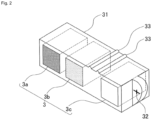
- FIG. 2 is an explanatory view of a portion related to the reference body 3 of the bone density measurement system 100 according to an embodiment of the present invention.
- the reference 3 is composed of samples 3a, 3b and 3c from which three levels of image density can be obtained.
- the correlation between each sample of the reference body 3 and the bone density equivalent value is, for example,
- Reference body 3 a mixing ratio 20% bone density equivalent value 0.50 g / square cm
- Reference body 3b mixture ratio 60% bone density equivalent value 0.75 g / square cm
- Reference body 3c Mixing ratio 100% Bone density equivalent value 1.00 g / square cm
- the mixing ratio is the ratio of homologues of hydroxyapatite to the whole, also referred to as apatite equivalent.
- Practical accuracy is obtained with a three-step reference. Of course, more detailed stages, for example, four to five stages of references may be used, which makes handling more complicated, but can be expected to improve the accuracy.
- the determination of the equivalent bone density value of the reference body may be a theoretical value calculated from the composition of the reference body, the correlation between the concentration and the bone density has been determined, for example, gbone mineral quantitative phantom h or gbone density You may obtain
- the approximate dimensions of the reference body 3 are, for example, a square having a side of 5 mm on a side facing the photographing device 2 and a depth of about 10 mm, but the dimensions are limited to this size. Since it is customary that bone density is expressed in g / square cm, the thickness may be similar to that of a hard tissue such as a bone to be measured. For example, it may be 8 mm for the lower front teeth, 10 mm for the premolars, and 12 mm for the molars.
- the reference body 3 is inserted into and accommodated in the hole provided in the case 31, and the case 31 further extends in the direction of the reference body 3 by, for example, a copper metal wire or the like on the extension of the row of reference bodies.
- the position, shape, etc. of the marker are not limited to those shown in this figure, as long as automatic reading is easy, and the insertion direction of the reference body 3 is not limited to the side from the marker 32 as shown. , From the opposite side, from the top, or from the bottom.
- two protrusions 33 are provided on the top surface of the case 31. This is for positioning and fixing at the time of assembly.
- the approximate dimensions of the case 31 are preferably, for example, about 7 mm ⁇ 24 mm on the side facing the imaging device 2 and about 10 mm in depth, but are not limited thereto. It is not always necessary to be accommodated in the case 31. Automatic reading may be performed using the position of the image, the shape of the reference body, etc. without the marker 32, or the operator of the apparatus Reading may be supported by an input unit such as a mouse.
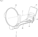
- FIG. 3 and FIG. 4 are explanatory diagrams of the imaging aid 4 of the bone density measurement system 100 according to the embodiment of the present invention.
- the photographing aid 4 holds the reference body 3 in order to simultaneously photograph the reference body 3 and the alveolar bone portion B, and the reference body 3 is accommodated in the case 31 to which the marker 32 is attached. It shall be held in the state.
- the reference body 3 itself may be fixed to the photographing aid 4 and held.
- the imaging aid 4 holds the planar imaging plate 21 for capturing an X-ray image at one end of the holding portion 41 and the holding portion 41 sandwiching and holding the planar imaging plate 21 substantially orthogonal to the imaging main axis Z of the main body of the imaging device 2
- An elongated rod-like support portion 42 is provided to be substantially orthogonal to 41 and is held on the opposite side of the holding portion 41 of the support portion 42 for supporting the holding portion 41 in an appropriate position by engaging the upper and lower teeth with the upper and lower teeth.
- it is a space provided in the center of the direction indication guide 43 so that the photographed image is rectangular.
- FIG. 4 does not have the rectangular stop 431 and the inside of the direction indication guide 43 is a large space, and such a simple structure may be used if it is not necessary to narrow it to the rectangular shape. Good. Furthermore, the direction indication guide 43 itself may not necessarily be provided depending on the photographing method and the like.
- the case 31 accommodating the reference body 3 is installed so as to be detected by the imaging plate 21 together with the alveolar bone portion.
- the case 31 containing the reference body 3 is inserted into a substantially U-shaped space formed at the end of the support portion 42 on the side of the holding portion 41, and two places provided on the case 31 side
- the projection 33 is fixed by fitting in a groove on the side of the support 42 not shown.
- the installation place and the fixing method of the case 31 accommodating the reference body 3 are not limited to the above description, and may be installed in the holding portion 41, and the fixing method may be a known method such as screwing.
- the reference body 3 and the marker 32 may be fixed to the support portion 42 or the holding portion 41 without using the case 31.
- the imaging aid 4 may be used for imaging bone parts other than alveolar bone parts.
- the shape of the holder 4 for holding the imaging plate 21 and the case 31 containing the reference 3 or the reference 3 itself and the support 42 for properly supporting the holder 41 is It should be designed together, in short, it should be able to capture the bone and the reference body 3 on the same screen.
- FIG. 5 is a functional configuration diagram of a bone density measurement device 1 according to an embodiment of the present invention.
- the bone density measuring apparatus 1 has the same screen of the X-ray images of the bones such as alveolar bones and the reference body for bone density measurement taken as the functional elements realized by the hardware components described above in cooperation with each other.
- FIG. 6 is an operation flow of a bone density measurement system 100 according to an embodiment of the present invention.
- the bone density measuring apparatus 1 indicates the region to be measured for the subject whose bone density is to be measured via the display unit 11, and instructs attachment of the imaging aid 4 (step S01).
- the tip portion (tooth top portion) of the tooth to be imaged is placed on the case 31 storing the reference body 3 and the holding portion 41 holding the imaging plate 21 is targeted
- the occlusal portion 42 is engaged with the subject and fixed so as to be directed to the root direction (upward) inside the teeth.
- the upper and lower sides of the holding portion 41 are reversed.
- the imaging device 2 is fixed with its leading portion abutting on the direction indication guide 43 so that the imaging main axis Z is substantially perpendicular to the imaging plate 21 so that the reference body 3 and the alveolar bone portion are the same
- the image is taken by the intraoral method so that the image is captured on the imaging plate 21 (step S02).
- the bone densitometry device 1 is read from the imaging plate 21 via the main body of the imaging device 2 or by causing the imaging plate 21 to be read directly by the input unit 12 of the bone densitometry device measurement device 1
- the photographed image information is received, and the image display unit 101 displays the photographed image (step S03).
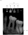
- FIG. 7 shows an example of a photographed image of the bone density measurement system according to an embodiment of the present invention.
- the image display unit 101 of the bone density measurement device 1 displays the image of the alveolar bone portion B in the lower part.
- the image of is placed at the top and displayed on the same screen.
- the images of the reference body samples 3a, 3b and 3c from which the image density of three levels can be obtained sequentially from the left in the figure and the image of the marker 32 for automatic measurement are displayed. Be done.
- the marker 32 and the reference body 3 are not aligned in the horizontal direction, and are photographed in a slightly inclined state. There are various situations of shooting, and even when they shift from the horizontal direction as described above, it often occurs, so a method that can accurately grasp the reference body 3 is required.
- FIG. 8 is an operation flow of setting a reference body region of interest of the bone density measurement system according to an embodiment of the present invention.
- center coordinates of the marker 32 are extracted on the image (step S11). Specifically, using the fact that the image of the marker 32 is a relatively thin line and having high luminance, only the image of the marker 32 part is determined by a method such as gray scale OPENING processing, image difference processing, etc., and its center coordinates Extract (Position) In addition, extraction of the center coordinates of the marker 32 is not limited to this method, and may be searched by pattern matching, for example.
- the center coordinates of the farthest reference body sample 3a are determined (step S12). Specifically, the side in the substantially horizontal direction of the marker 32 is extended, and the position of the distance on the image corresponding to the distance to the farthest reference body sample 3c set in advance is set as the center coordinate.
- FIG. 9 is an example of an image related to the reference body region of interest setting unit of the bone density measurement system according to one embodiment of the present invention, in which the center coordinates of the marker 32 and the center coordinates of the farthest reference body sample 3a are shown.
- the region of interest of the reference body is determined using the center coordinates of the marker 32 and the center coordinates of the farthest reference body sample 3a (step S13). Specifically, as shown in FIG. 9 , the distance between the center coordinates of the marker 32 and the center coordinates of the farthest reference body sample 3a is divided by a predetermined ratio (for example, as shown in FIG. 9 ). : M: n) Then, the center coordinates of the other reference body samples 3c, 3b are determined.
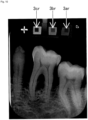
- FIG. 10 is an example of an image related to a reference body region of interest setting unit of the bone density measurement system according to an embodiment of the present invention, showing a state in which the region of interest is set.
- the image of the reference body 3 is often photographed tilted from the horizontal direction, and a correction is necessary because there are subtle errors due to the influence of the X-ray incident angle and so on.
- the image of the reference body is confirmed from the relative value of the distance to the reference body sample 3a, 3b, 3c from the image of, and further, the region of interest is created with a coefficient that minimizes the variance of the concentration in the region of interest.
- a method such as
- each of the reference body regions of interest 3ar, 3br, and 3cr is a square with one side of 30 pixels.
- the region of interest of the reference body can be automatically and accurately performed without human intervention, and the effect is large.
- the image shown in FIG. 9 may be presented on the screen to prompt the operator for input.
- the reference body density measurement unit 103 measures the image density of the reference body samples 3a, 3b, and 3c from the image of the region of interest of the reference body 3 by a known method (Step S04 in FIG. 6 ).
- a representative value of concentration any of average value, median value and mode value can be set according to the situation.
- the central value as the representative value of the concentration, so it is desirable to use an average value or median value, especially when the concentration distribution is stable. Average value is most desirable.
- the mode in the case of a concentration distribution in which only a portion is pointed like the concentration of the marker 32, it is preferable to use the mode as it is preferable to set the pointed portion as the representative value of the concentration.
- FIG. 11 is a diagram showing the correlation between the density of an image of a reference body and bone density in an embodiment of the present invention. That is, in the case of the above-mentioned example, as a result of measurement, it became as follows.
- Reference body 3 a concentration 96 bone density equivalent value 0.50 g / square cm
- FIG. 12 is an explanatory view showing a method of setting a bone region of interest in the bone densitometry device according to one embodiment of the present invention, and the width w at a position approximately equidistantly spaced on both sides of a tooth axis of a specific tooth; Two bone regions of interest Br1 and Br2 of the dimension of height h are set.
- the specification of the teeth and the specification of the area may be appropriately determined according to the application of bone density measurement.
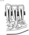
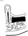
- FIGS. 13A to 13F are explanatory views showing an example of a bone region of interest in a bone density measurement device according to an embodiment of the present invention, wherein the black parts indicate the bone region of interest and the alveolar bone mentioned above Alveolar crest ( FIG. 13B ), apical bone ( FIG. 13C ), jawbone bone body ( FIG. 13D ), extraction pits ( FIG. 13E ), jaw ridges ( FIG. 13E ) as well as the bony bone body part It may be a part to be treated such as an implant or a technician ( FIG. 13F ) or the like, and the predetermined distance and size may be appropriately selected.
- FIG. 13E and FIG. 13F are useful for evaluating the progress of treatment and planning of treatment planning for the dentist, and the others are particularly based on the quantitative evaluation of alveolar bone resorption. It is useful for diagnosis support of periodontal disease.
- the region may not necessarily be set, and a specific portion may be designated to measure the concentration at that portion.
- the bone part concentration measurement unit 105 measures the concentration of the bone part, in particular, the region of interest in the alveolar bone part (step S06 in FIG. 6 ).
- a representative value of the concentration is determined for the bone region of interest in the alveolar bone portion described above.
- the region of interest of the alveolar bone portion can be a region of interest that simultaneously includes a tooth region and a non-tooth region because the user can arbitrarily select it.
- the representative value is set to one of an average value, a median value, and a mode value.
- the concentration is determined to be 120 as a representative value.
- the concentration may be obtained by other methods such as the concentration of only a specific part. In some cases, it can be measured simply.
- the bone density calculation unit 106 calculates the bone density of the alveolar bone from the correlation between the density of the reference body and the bone density and the concentration of the region of interest in the alveolar bone (step S07 in FIG. 6 ).
- the bone density at the concentration 120 is calculated to be about 0.71 g / square cm. In this way, the bone density of the alveolar bone portion can be obtained in g / square cm, which is a general-purpose unit.
- FIG. 14 is an example of a film image, not a digital image, but in this case it looks The density (pixel value) is significantly reduced, but since all of the reference body regions of interest 3a, 3b, 3c and the bone portion of interest region Br are similarly reduced in density, FIG. By creating a correlation diagram in the same manner, bone density can be calculated appropriately.
- the present application has broad industrial applicability in that it can measure bone density using dental x-ray images and can be used to support the diagnosis of osteoporosis and the like.
Landscapes
- Health & Medical Sciences (AREA)
- Life Sciences & Earth Sciences (AREA)
- Engineering & Computer Science (AREA)
- Medical Informatics (AREA)
- Radiology & Medical Imaging (AREA)
- Molecular Biology (AREA)
- Biophysics (AREA)
- High Energy & Nuclear Physics (AREA)
- Veterinary Medicine (AREA)
- Nuclear Medicine, Radiotherapy & Molecular Imaging (AREA)
- Optics & Photonics (AREA)
- Pathology (AREA)
- Public Health (AREA)
- Biomedical Technology (AREA)
- Heart & Thoracic Surgery (AREA)
- Physics & Mathematics (AREA)
- Surgery (AREA)
- Animal Behavior & Ethology (AREA)
- General Health & Medical Sciences (AREA)
- Dentistry (AREA)
- Oral & Maxillofacial Surgery (AREA)
- Computer Vision & Pattern Recognition (AREA)
- Human Computer Interaction (AREA)
- Physiology (AREA)
- Orthopedic Medicine & Surgery (AREA)
- Apparatus For Radiation Diagnosis (AREA)
Claims (13)
- Knochendichtemessgerät (1), umfassend:eine Bildanzeigeeinheit (101) zum Anzeigen eines Röntgenbildes bezüglich eines fotografierten Knochenabschnitts eines Zielzahns einer Person und mehrerer Referenzkörper (3), deren Knochendichtewerte angegeben sind, auf demselben Bildschirm, wobei das Röntgenbild ein Bild ist, das mit einer Bildgebungshilfe (4) aufgenommen wurde, die einen Halteabschnitt (41) zum Halten einer planaren Bildgebungsplatte (21), die das Röntgenbild aufnimmt, umfasst, wobei die Bildgebungsplatte im Wesentlichen orthogonal zur Bildgebungshauptachse (Z) des Hauptkörpers der Bildgebungshilfe (4) angeordnet ist, wobei an einem Ende des Halteabschnitts (41) ein länglicher stabförmiger Stützabschnitt (42) vorgesehen ist für ein Stützen des Halteabschnitts (41) an einer geeigneten Position, wenn der Stützabschnitt (42) mit der abzubildenden Person in Eingriff steht und so fixiert ist, dass er in Richtung der Zahnwurzel gerichtet ist, und wobei des Weiteren ein Gehäuse (31), das die Referenzkörper (3a, 3b, 3c) beherbergt, an dem Endabschnitt des Stützabschnitts (42) auf der Seite des Halteabschnitts (41) so angebracht ist, dass die Referenzkörper (3a, 3b, 3c) von der Bildgebungsplatte (21) zusammen mit dem Alveolarknochenabschnitt des Zielzahns erfasst werden können,eine Einheit zur Messung der Bilddichte eines Referenzkörpers (103), die konfiguriert ist, die Dichte des Röntgenbilds der angezeigten mehreren Referenzkörper zu messen,eine Einheit zur Messung der Bilddichte eines Knochenabschnitts (105), die konfiguriert ist, die Dichte des Röntgenbilds des angezeigten Knochenabschnitts zu messen,eine Einheit zur Berechnung der Knochendichte (106), die konfiguriert ist, die Knochendichte des Knochenabschnitts durch Vergleichen der Dichte des Röntgenbilds des Knochenabschnitts mit der Dichte des Röntgenbilds der Referenzkörper zu berechnen,wobeidie Einheit zur Berechnung der Knochendichte (106) konfiguriert ist, die Berechnung der Knochendichte des Knochenabschnitts durch (a) Ermitteln einer Beziehung zwischen der Röntgenbilddichte der mehreren Referenzkörper (3) und dem entsprechenden Knochendichtewert, (b) Approximieren der ermittelten Beziehung, um eine durch eine lineare Regressionsgerade ausgedrückte Beziehung zwischen den Röntgenbilddichten der Referenzkörper (3) und den entsprechenden Knochendichtewerten zu erhalten, und (c) Verwenden der linearen Regressionsgeraden als Referenz zum Berechnen der Knochendichte des Knochenabschnitts auf Basis der gemessenen Röntgenbilddichte des Knochenabschnitts durchzuführen.
- Knochendichtemessgerät (1) gemäß Anspruch 1, wobei die Referenzkörper (3) eine Zusammensetzung aufweisen, die derjenigen eines Zahns nahekommt.
- Knochendichtemessgerät (1) gemäß Anspruch 2, wobei die Referenzkörper (3) dadurch gekennzeichnet sind, dass der Hydroxylapatit oder ein Hydroxylapatit-Homolog, bei dem die OH-Gruppe des Apatits durch ein anderes Element substituiert ist, mit Kohlenstoff in unterschiedlichen Mischungsverhältnissen vermischt ist.
- Knochendichtemessgerät (1) gemäß Anspruch 1, wobei die Referenzkörper (3) eine Probe, von der drei Bilddichtestufen erhalten werden können, umfasst, und wobei die Einheit zur Berechnung der Knochendichte (106) die Knochendichte unter Verwendung der drei Bilddichtestufen berechnet.
- Knochendichtemessgerät (1) gemäß Anspruch 1, wobei die Messung der Referenzkörper (3) durch Lesen einer Markierung gestartet wird, die an einem die Referenzkörper (3) enthaltenden Gehäuse angebracht ist.
- Knochendichtemessgerät (1) gemäß Anspruch 5, das des Weiteren eine Einheit zum Festlegen eines interessierenden Bereichs der Referenzkörper umfasst, die einen interessierenden Bereich der Referenzkörper festlegt.
- Knochendichte-Messsystem (100), umfassend:Referenzkörper (3) zur Messung der Knochendichte,eine Bildgebungsvorrichtung (2) zum gleichzeitigen Abbilden eines Röntgenbilds eines Knochenabschnitts und eines Röntgenbilds der Referenzkörper (3) undeine Vorrichtung zur Messung der Knochendichte (1) gemäß Anspruch 1.
- Knochendichte-Messsystem (100) gemäß Anspruch 7, wobei die Referenzkörper (3) eine Zusammensetzung aufweisen, die derjenigen eines Zahns nahekommt.
- Knochendichte-Messsystem (100) gemäß Anspruch 7, wobei die Referenzkörper (3) durch Mischen von Hydroxylapatit oder einem Hydroxylapatit-Homolog, das durch Substituieren der OH-Gruppe des Apatits durch ein anderes Element erhalten wird, und Kohlenstoff in unterschiedlichen Mischungsverhältnissen gebildet sind.
- Knochendichte-Messsystem (100) gemäß Anspruch 7, wobei die Referenzkörper (3) eine Probe umfassen, die in der Lage ist, drei Bilddichtestufen zu erhalten.
- Knochendichte-Messsystem (100) gemäß Anspruch 7, des Weiteren umfassend:ein Gehäuse zum Beherbergen der Referenzkörper (3) undeine automatisch lesbare Markierung, die auf dem Gehäuse vorgesehen ist.
- Knochendichte-Messsystem (100) gemäß Anspruch 7, das des Weiteren eine Vorrichtung zur Unterstützung des Fotografierens (4) umfasst, die zum Halten der Referenzkörper (3) für ein gleichzeitiges Fotografieren der Referenzkörper (3) und des Knochenabschnitt konfiguriert ist.
- Knochendichte-Messsystem (100) gemäß Anspruch 12,
wobei die Vorrichtung zur Unterstützung des Fotografierens (4) einen Mechanismus umfasst, der konfiguriert ist, die Referenzkörper auf der Seite des Trägerabschnitts (42) des Halteabschnitts (41) so zu halten, dass sie mittels des Mediums zum Ermitteln von Bildinformationen zusammen mit dem Knochenabschnitt erfasst werden.
Applications Claiming Priority (2)
| Application Number | Priority Date | Filing Date | Title |
|---|---|---|---|
| JP2017002038 | 2017-01-10 | ||
| PCT/JP2018/000357 WO2018131611A1 (ja) | 2017-01-10 | 2018-01-10 | 骨密度測定装置、骨密度測定システム及び撮影補助具 |
Publications (3)
| Publication Number | Publication Date |
|---|---|
| EP3569149A1 EP3569149A1 (de) | 2019-11-20 |
| EP3569149A4 EP3569149A4 (de) | 2020-11-04 |
| EP3569149B1 true EP3569149B1 (de) | 2024-08-07 |
Family
ID=62840414
Family Applications (1)
| Application Number | Title | Priority Date | Filing Date |
|---|---|---|---|
| EP18739311.1A Active EP3569149B1 (de) | 2017-01-10 | 2018-01-10 | Vorrichtung zur messung der knochendichte, knochendichtemesssystem und bildgebungsassistenzinstrument |
Country Status (5)
| Country | Link |
|---|---|
| US (1) | US11191507B2 (de) |
| EP (1) | EP3569149B1 (de) |
| JP (1) | JP7150234B2 (de) |
| CN (1) | CN110381837A (de) |
| WO (1) | WO2018131611A1 (de) |
Families Citing this family (3)
| Publication number | Priority date | Publication date | Assignee | Title |
|---|---|---|---|---|
| US11191507B2 (en) * | 2017-01-10 | 2021-12-07 | Media Co., Ltd. | Bone density measurement device, bone density measurement system, and imaging assisting tool |
| JP7440271B2 (ja) * | 2020-01-10 | 2024-02-28 | 富士フイルムヘルスケア株式会社 | 放射線撮像装置および光子計数型検出器の較正方法 |
| CN117137439A (zh) * | 2023-08-22 | 2023-12-01 | 联影智能医疗科技(北京)有限公司 | 一种容积骨密度的测量方法、装置及存储介质 |
Citations (2)
| Publication number | Priority date | Publication date | Assignee | Title |
|---|---|---|---|---|
| JPH07102210B2 (ja) * | 1986-05-14 | 1995-11-08 | 帝人株式会社 | 歯槽骨の骨萎縮度評価法 |
| JP2004275334A (ja) * | 2003-03-14 | 2004-10-07 | Hitachi Medical Corp | X線ctによる骨密度評価器具とそれを用いた骨密度評価システム |
Family Cites Families (22)
| Publication number | Priority date | Publication date | Assignee | Title |
|---|---|---|---|---|
| CA1288176C (en) * | 1987-10-29 | 1991-08-27 | David C. Hatcher | Method and apparatus for improving the alignment of radiographic images |
| JP2719089B2 (ja) * | 1993-03-31 | 1998-02-25 | 通夫 岡田 | X線フィルム体並びに基準用金属片付きシート体、及びx線撮影装置 |
| JP3824749B2 (ja) * | 1996-09-25 | 2006-09-20 | 富士写真フイルム株式会社 | 骨部画像処理方法および装置 |
| US6320931B1 (en) * | 1998-03-02 | 2001-11-20 | Image Analysis, Inc. | Automated x-ray bone densitometer |
| JP3300690B2 (ja) * | 1999-10-25 | 2002-07-08 | 信治 下田 | 標準試料及びその製造方法 |
| US6246745B1 (en) * | 1999-10-29 | 2001-06-12 | Compumed, Inc. | Method and apparatus for determining bone mineral density |
| US7050534B2 (en) * | 2000-08-29 | 2006-05-23 | Imaging Therapeutics, Inc. | Methods and devices for quantitative analysis of x-ray images |
| US6904123B2 (en) * | 2000-08-29 | 2005-06-07 | Imaging Therapeutics, Inc. | Methods and devices for quantitative analysis of x-ray images |
| CN1498385A (zh) * | 2000-08-29 | 2004-05-19 | X图像量析的方法与装置 | |
| JP2003300690A (ja) * | 2002-04-11 | 2003-10-21 | Hitachi Constr Mach Co Ltd | 建設機械の表示装置 |
| JP3721517B2 (ja) * | 2002-08-22 | 2005-11-30 | 清水建設株式会社 | 鋼板の曲げ加工における機械的性質に及ぼす加工度と焼き鈍し処理の影響評価法 |
| JP2004174162A (ja) * | 2002-11-29 | 2004-06-24 | Hanshin Gijutsu Kenkyusho:Kk | 歯科用x線撮影具 |
| CA2519187A1 (en) * | 2003-03-25 | 2004-10-14 | Imaging Therapeutics, Inc. | Methods for the compensation of imaging technique in the processing of radiographic images |
| US7488109B2 (en) * | 2003-03-27 | 2009-02-10 | Wright State University | Osteoporosis screening using radiographic absorptiometry of the mandible |
| JP4077430B2 (ja) | 2003-07-31 | 2008-04-16 | 佳知 高石 | 骨密度評価装置および骨密度評価方法 |
| DE102005021327A1 (de) * | 2005-05-04 | 2006-11-16 | "Stiftung Caesar" (Center Of Advanced European Studies And Research) | Verfahren und System zur Knochendichtekalibrierung |
| JP4640492B2 (ja) * | 2008-10-27 | 2011-03-02 | パナソニック電工株式会社 | 骨密度計測装置 |
| US8186880B1 (en) * | 2008-11-27 | 2012-05-29 | Arnold Ben A | Extended and fixed INTable simultaneously imaged calibration and correction methods and references for 3-D imaging devices |
| KR101087137B1 (ko) * | 2008-12-04 | 2011-11-25 | 한국전자통신연구원 | 악골밀도 측정 방법 및 악골밀도 측정을 위한 보조장치 |
| JP6335287B2 (ja) * | 2013-07-03 | 2018-05-30 | ゼネラル・エレクトリック・カンパニイ | 造影式乳房撮像方法及び造影剤基準挿入体 |
| JP2018511791A (ja) * | 2015-02-27 | 2018-04-26 | バイエル・ヘルスケア・エルエルシーBayer HealthCare LLC | マルチイメージングモダリティ用定量的ファントム |
| US11191507B2 (en) * | 2017-01-10 | 2021-12-07 | Media Co., Ltd. | Bone density measurement device, bone density measurement system, and imaging assisting tool |
-
2018
- 2018-01-10 US US16/477,170 patent/US11191507B2/en active Active
- 2018-01-10 EP EP18739311.1A patent/EP3569149B1/de active Active
- 2018-01-10 JP JP2018561391A patent/JP7150234B2/ja active Active
- 2018-01-10 CN CN201880016131.5A patent/CN110381837A/zh active Pending
- 2018-01-10 WO PCT/JP2018/000357 patent/WO2018131611A1/ja not_active Ceased
Patent Citations (2)
| Publication number | Priority date | Publication date | Assignee | Title |
|---|---|---|---|---|
| JPH07102210B2 (ja) * | 1986-05-14 | 1995-11-08 | 帝人株式会社 | 歯槽骨の骨萎縮度評価法 |
| JP2004275334A (ja) * | 2003-03-14 | 2004-10-07 | Hitachi Medical Corp | X線ctによる骨密度評価器具とそれを用いた骨密度評価システム |
Non-Patent Citations (1)
| Title |
|---|
| YANG ET AL: "A new device for measuring density of jaw bones", vol. 31, no. 5, 1 September 2002 (2002-09-01), pages 313 - 316, XP009531389, ISSN: 0250-832X, Retrieved from the Internet <URL:https://doi.org/10.1038/sj.dmfr.4600715?locatt=mode:legacy> [retrieved on 20140128], DOI: 10.1038/SJ.DMFR.4600715 * |
Also Published As
| Publication number | Publication date |
|---|---|
| CN110381837A (zh) | 2019-10-25 |
| EP3569149A4 (de) | 2020-11-04 |
| JPWO2018131611A1 (ja) | 2019-11-07 |
| US20190343475A1 (en) | 2019-11-14 |
| EP3569149A1 (de) | 2019-11-20 |
| WO2018131611A1 (ja) | 2018-07-19 |
| US11191507B2 (en) | 2021-12-07 |
| JP7150234B2 (ja) | 2022-10-11 |
Similar Documents
| Publication | Publication Date | Title |
|---|---|---|
| Yılmaz et al. | Endodontic working length measurement using cone-beam computed tomographic images obtained at different voxel sizes and field of views, periapical radiography, and apex locator: a comparative ex vivo study | |
| Kamburoğlu et al. | Detection of vertical root fracture using cone-beam computerized tomography: an in vitro assessment | |
| Sherrard et al. | Accuracy and reliability of tooth and root lengths measured on cone-beam computed tomographs | |
| Reddy | Radiographic methods in the evaluation of periodontal therapy | |
| Kullendorff et al. | Diagnostic accuracy of direct digital dental radiography for the detection of periapical bone lesions: overall comparison between conventional and direct digital radiography | |
| Vandenberghe et al. | Diagnostic validity (or acuity) of 2D CCD versus 3D CBCT-images for assessing periodontal breakdown | |
| US6405071B1 (en) | Three dimensional imaging and analysis of a root canal | |
| Cook et al. | Accuracy of alveolar bone measurements from cone beam computed tomography acquired using varying settings | |
| Belém et al. | Performance of digital radiography with enhancement filters for the diagnosis of proximal caries | |
| Zhang et al. | The detection accuracies for proximal caries by cone-beam computerized tomography, film, and phosphor plates | |
| Hu et al. | Reliability of two different presurgical preparation methods for implant dentistry based on panoramic radiography and cone-beam computed tomography in cadavers | |
| Metska et al. | Cone-beam computed tomographic scans in comparison with periapical radiographs for root canal length measurement: an in situ study | |
| Heo et al. | Quantitative analysis of apical root resorption by means of digital subtraction radiography | |
| Al-Falahi et al. | Three-dimensional assessment of external apical root resorption after maxillary posterior teeth intrusion with miniscrews in anterior open bite patients | |
| Kamburoğlu et al. | Diagnosis of artificially induced external root resorption using conventional intraoral film radiography, CCD, and PSP: an ex vivo study | |
| Møller et al. | Comparison of images from digital intraoral receptors and cone beam computed tomography scanning for detection of voids in root canal fillings: an in vitro study using micro-computed tomography as validation | |
| EP3569149A1 (de) | Vorrichtung zur messung der knochendichte, knochendichtemesssystem und bildgebungsassistenzinstrument | |
| Liedke et al. | Accuracy of detecting and measuring buccal bone thickness adjacent to titanium dental implants—a cone beam computed tomography in vitro study | |
| Salian et al. | Radiographic evaluation in implant patients: A review | |
| Rawlinson et al. | An in-vitro and in-vivo methodology study of alveolar bone measurement using extra-oral radiographic alignment apparatus, Image Pro-Plus® software and a subtraction programme | |
| Duinkerke et al. | Evaluation of a technique for standardized periapical radiographs | |
| Athar et al. | Radiographic endodontic working length estimation: comparison of three digital image receptors | |
| Ajmal | Evaluation of mental foramen position from panoramic dental radiographs | |
| Yi et al. | ROI-based image registration for digital subtraction radiography | |
| Huh et al. | Quantitative analysis of errors in alveolar crest level caused by discrepant projection geometry in digital subtraction radiography: an in vivo study |
Legal Events
| Date | Code | Title | Description |
|---|---|---|---|
| STAA | Information on the status of an ep patent application or granted ep patent |
Free format text: STATUS: THE INTERNATIONAL PUBLICATION HAS BEEN MADE |
|
| PUAI | Public reference made under article 153(3) epc to a published international application that has entered the european phase |
Free format text: ORIGINAL CODE: 0009012 |
|
| STAA | Information on the status of an ep patent application or granted ep patent |
Free format text: STATUS: REQUEST FOR EXAMINATION WAS MADE |
|
| 17P | Request for examination filed |
Effective date: 20190731 |
|
| AK | Designated contracting states |
Kind code of ref document: A1 Designated state(s): AL AT BE BG CH CY CZ DE DK EE ES FI FR GB GR HR HU IE IS IT LI LT LU LV MC MK MT NL NO PL PT RO RS SE SI SK SM TR |
|
| AX | Request for extension of the european patent |
Extension state: BA ME |
|
| DAV | Request for validation of the european patent (deleted) | ||
| DAX | Request for extension of the european patent (deleted) | ||
| REG | Reference to a national code |
Ref country code: DE Ref legal event code: R079 Ipc: A61B0006140000 Ref country code: DE Ref legal event code: R079 Ref document number: 602018072752 Country of ref document: DE Free format text: PREVIOUS MAIN CLASS: A61B0006000000 Ipc: A61B0006140000 |
|
| A4 | Supplementary search report drawn up and despatched |
Effective date: 20201007 |
|
| RIC1 | Information provided on ipc code assigned before grant |
Ipc: A61B 6/14 20060101AFI20201001BHEP |
|
| STAA | Information on the status of an ep patent application or granted ep patent |
Free format text: STATUS: EXAMINATION IS IN PROGRESS |
|
| 17Q | First examination report despatched |
Effective date: 20221103 |
|
| GRAP | Despatch of communication of intention to grant a patent |
Free format text: ORIGINAL CODE: EPIDOSNIGR1 |
|
| REG | Reference to a national code |
Ref country code: DE Ref legal event code: R079 Free format text: PREVIOUS MAIN CLASS: A61B0006140000 Ipc: A61B0006510000 Ref document number: 602018072752 Country of ref document: DE |
|
| STAA | Information on the status of an ep patent application or granted ep patent |
Free format text: STATUS: GRANT OF PATENT IS INTENDED |
|
| GRAJ | Information related to disapproval of communication of intention to grant by the applicant or resumption of examination proceedings by the epo deleted |
Free format text: ORIGINAL CODE: EPIDOSDIGR1 |
|
| STAA | Information on the status of an ep patent application or granted ep patent |
Free format text: STATUS: EXAMINATION IS IN PROGRESS |
|
| INTG | Intention to grant announced |
Effective date: 20240116 |
|
| RIC1 | Information provided on ipc code assigned before grant |
Ipc: A61B 6/51 20240101AFI20240115BHEP |
|
| INTC | Intention to grant announced (deleted) | ||
| GRAP | Despatch of communication of intention to grant a patent |
Free format text: ORIGINAL CODE: EPIDOSNIGR1 |
|
| STAA | Information on the status of an ep patent application or granted ep patent |
Free format text: STATUS: GRANT OF PATENT IS INTENDED |
|
| INTG | Intention to grant announced |
Effective date: 20240304 |
|
| GRAS | Grant fee paid |
Free format text: ORIGINAL CODE: EPIDOSNIGR3 |
|
| GRAA | (expected) grant |
Free format text: ORIGINAL CODE: 0009210 |
|
| STAA | Information on the status of an ep patent application or granted ep patent |
Free format text: STATUS: THE PATENT HAS BEEN GRANTED |
|
| AK | Designated contracting states |
Kind code of ref document: B1 Designated state(s): AL AT BE BG CH CY CZ DE DK EE ES FI FR GB GR HR HU IE IS IT LI LT LU LV MC MK MT NL NO PL PT RO RS SE SI SK SM TR |
|
| REG | Reference to a national code |
Ref country code: GB Ref legal event code: FG4D |
|
| REG | Reference to a national code |
Ref country code: CH Ref legal event code: EP |
|
| REG | Reference to a national code |
Ref country code: DE Ref legal event code: R096 Ref document number: 602018072752 Country of ref document: DE |
|
| REG | Reference to a national code |
Ref country code: IE Ref legal event code: FG4D |
|
| REG | Reference to a national code |
Ref country code: LT Ref legal event code: MG9D |
|
| REG | Reference to a national code |
Ref country code: NL Ref legal event code: MP Effective date: 20240807 |
|
| PG25 | Lapsed in a contracting state [announced via postgrant information from national office to epo] |
Ref country code: NO Free format text: LAPSE BECAUSE OF FAILURE TO SUBMIT A TRANSLATION OF THE DESCRIPTION OR TO PAY THE FEE WITHIN THE PRESCRIBED TIME-LIMIT Effective date: 20241107 |
|
| REG | Reference to a national code |
Ref country code: AT Ref legal event code: MK05 Ref document number: 1710021 Country of ref document: AT Kind code of ref document: T Effective date: 20240807 |
|
| PG25 | Lapsed in a contracting state [announced via postgrant information from national office to epo] |
Ref country code: PT Free format text: LAPSE BECAUSE OF FAILURE TO SUBMIT A TRANSLATION OF THE DESCRIPTION OR TO PAY THE FEE WITHIN THE PRESCRIBED TIME-LIMIT Effective date: 20241209 Ref country code: FI Free format text: LAPSE BECAUSE OF FAILURE TO SUBMIT A TRANSLATION OF THE DESCRIPTION OR TO PAY THE FEE WITHIN THE PRESCRIBED TIME-LIMIT Effective date: 20240807 Ref country code: NL Free format text: LAPSE BECAUSE OF FAILURE TO SUBMIT A TRANSLATION OF THE DESCRIPTION OR TO PAY THE FEE WITHIN THE PRESCRIBED TIME-LIMIT Effective date: 20240807 Ref country code: PL Free format text: LAPSE BECAUSE OF FAILURE TO SUBMIT A TRANSLATION OF THE DESCRIPTION OR TO PAY THE FEE WITHIN THE PRESCRIBED TIME-LIMIT Effective date: 20240807 Ref country code: GR Free format text: LAPSE BECAUSE OF FAILURE TO SUBMIT A TRANSLATION OF THE DESCRIPTION OR TO PAY THE FEE WITHIN THE PRESCRIBED TIME-LIMIT Effective date: 20241108 |
|
| PG25 | Lapsed in a contracting state [announced via postgrant information from national office to epo] |
Ref country code: BG Free format text: LAPSE BECAUSE OF FAILURE TO SUBMIT A TRANSLATION OF THE DESCRIPTION OR TO PAY THE FEE WITHIN THE PRESCRIBED TIME-LIMIT Effective date: 20240807 |
|
| PG25 | Lapsed in a contracting state [announced via postgrant information from national office to epo] |
Ref country code: LV Free format text: LAPSE BECAUSE OF FAILURE TO SUBMIT A TRANSLATION OF THE DESCRIPTION OR TO PAY THE FEE WITHIN THE PRESCRIBED TIME-LIMIT Effective date: 20240807 |
|
| PG25 | Lapsed in a contracting state [announced via postgrant information from national office to epo] |
Ref country code: AT Free format text: LAPSE BECAUSE OF FAILURE TO SUBMIT A TRANSLATION OF THE DESCRIPTION OR TO PAY THE FEE WITHIN THE PRESCRIBED TIME-LIMIT Effective date: 20240807 Ref country code: IS Free format text: LAPSE BECAUSE OF FAILURE TO SUBMIT A TRANSLATION OF THE DESCRIPTION OR TO PAY THE FEE WITHIN THE PRESCRIBED TIME-LIMIT Effective date: 20241207 |
|
| PG25 | Lapsed in a contracting state [announced via postgrant information from national office to epo] |
Ref country code: HR Free format text: LAPSE BECAUSE OF FAILURE TO SUBMIT A TRANSLATION OF THE DESCRIPTION OR TO PAY THE FEE WITHIN THE PRESCRIBED TIME-LIMIT Effective date: 20240807 |
|
| PG25 | Lapsed in a contracting state [announced via postgrant information from national office to epo] |
Ref country code: RS Free format text: LAPSE BECAUSE OF FAILURE TO SUBMIT A TRANSLATION OF THE DESCRIPTION OR TO PAY THE FEE WITHIN THE PRESCRIBED TIME-LIMIT Effective date: 20241107 Ref country code: ES Free format text: LAPSE BECAUSE OF FAILURE TO SUBMIT A TRANSLATION OF THE DESCRIPTION OR TO PAY THE FEE WITHIN THE PRESCRIBED TIME-LIMIT Effective date: 20240807 |
|
| PG25 | Lapsed in a contracting state [announced via postgrant information from national office to epo] |
Ref country code: RS Free format text: LAPSE BECAUSE OF FAILURE TO SUBMIT A TRANSLATION OF THE DESCRIPTION OR TO PAY THE FEE WITHIN THE PRESCRIBED TIME-LIMIT Effective date: 20241107 Ref country code: PT Free format text: LAPSE BECAUSE OF FAILURE TO SUBMIT A TRANSLATION OF THE DESCRIPTION OR TO PAY THE FEE WITHIN THE PRESCRIBED TIME-LIMIT Effective date: 20241209 Ref country code: PL Free format text: LAPSE BECAUSE OF FAILURE TO SUBMIT A TRANSLATION OF THE DESCRIPTION OR TO PAY THE FEE WITHIN THE PRESCRIBED TIME-LIMIT Effective date: 20240807 Ref country code: NO Free format text: LAPSE BECAUSE OF FAILURE TO SUBMIT A TRANSLATION OF THE DESCRIPTION OR TO PAY THE FEE WITHIN THE PRESCRIBED TIME-LIMIT Effective date: 20241107 Ref country code: NL Free format text: LAPSE BECAUSE OF FAILURE TO SUBMIT A TRANSLATION OF THE DESCRIPTION OR TO PAY THE FEE WITHIN THE PRESCRIBED TIME-LIMIT Effective date: 20240807 Ref country code: LV Free format text: LAPSE BECAUSE OF FAILURE TO SUBMIT A TRANSLATION OF THE DESCRIPTION OR TO PAY THE FEE WITHIN THE PRESCRIBED TIME-LIMIT Effective date: 20240807 Ref country code: IS Free format text: LAPSE BECAUSE OF FAILURE TO SUBMIT A TRANSLATION OF THE DESCRIPTION OR TO PAY THE FEE WITHIN THE PRESCRIBED TIME-LIMIT Effective date: 20241207 Ref country code: HR Free format text: LAPSE BECAUSE OF FAILURE TO SUBMIT A TRANSLATION OF THE DESCRIPTION OR TO PAY THE FEE WITHIN THE PRESCRIBED TIME-LIMIT Effective date: 20240807 Ref country code: GR Free format text: LAPSE BECAUSE OF FAILURE TO SUBMIT A TRANSLATION OF THE DESCRIPTION OR TO PAY THE FEE WITHIN THE PRESCRIBED TIME-LIMIT Effective date: 20241108 Ref country code: FI Free format text: LAPSE BECAUSE OF FAILURE TO SUBMIT A TRANSLATION OF THE DESCRIPTION OR TO PAY THE FEE WITHIN THE PRESCRIBED TIME-LIMIT Effective date: 20240807 Ref country code: ES Free format text: LAPSE BECAUSE OF FAILURE TO SUBMIT A TRANSLATION OF THE DESCRIPTION OR TO PAY THE FEE WITHIN THE PRESCRIBED TIME-LIMIT Effective date: 20240807 Ref country code: BG Free format text: LAPSE BECAUSE OF FAILURE TO SUBMIT A TRANSLATION OF THE DESCRIPTION OR TO PAY THE FEE WITHIN THE PRESCRIBED TIME-LIMIT Effective date: 20240807 Ref country code: AT Free format text: LAPSE BECAUSE OF FAILURE TO SUBMIT A TRANSLATION OF THE DESCRIPTION OR TO PAY THE FEE WITHIN THE PRESCRIBED TIME-LIMIT Effective date: 20240807 |
|
| PG25 | Lapsed in a contracting state [announced via postgrant information from national office to epo] |
Ref country code: DK Free format text: LAPSE BECAUSE OF FAILURE TO SUBMIT A TRANSLATION OF THE DESCRIPTION OR TO PAY THE FEE WITHIN THE PRESCRIBED TIME-LIMIT Effective date: 20240807 Ref country code: RO Free format text: LAPSE BECAUSE OF FAILURE TO SUBMIT A TRANSLATION OF THE DESCRIPTION OR TO PAY THE FEE WITHIN THE PRESCRIBED TIME-LIMIT Effective date: 20240807 Ref country code: SM Free format text: LAPSE BECAUSE OF FAILURE TO SUBMIT A TRANSLATION OF THE DESCRIPTION OR TO PAY THE FEE WITHIN THE PRESCRIBED TIME-LIMIT Effective date: 20240807 |
|
| PG25 | Lapsed in a contracting state [announced via postgrant information from national office to epo] |
Ref country code: EE Free format text: LAPSE BECAUSE OF FAILURE TO SUBMIT A TRANSLATION OF THE DESCRIPTION OR TO PAY THE FEE WITHIN THE PRESCRIBED TIME-LIMIT Effective date: 20240807 |
|
| PG25 | Lapsed in a contracting state [announced via postgrant information from national office to epo] |
Ref country code: CZ Free format text: LAPSE BECAUSE OF FAILURE TO SUBMIT A TRANSLATION OF THE DESCRIPTION OR TO PAY THE FEE WITHIN THE PRESCRIBED TIME-LIMIT Effective date: 20240807 |
|
| PG25 | Lapsed in a contracting state [announced via postgrant information from national office to epo] |
Ref country code: SK Free format text: LAPSE BECAUSE OF FAILURE TO SUBMIT A TRANSLATION OF THE DESCRIPTION OR TO PAY THE FEE WITHIN THE PRESCRIBED TIME-LIMIT Effective date: 20240807 |
|
| REG | Reference to a national code |
Ref country code: DE Ref legal event code: R097 Ref document number: 602018072752 Country of ref document: DE |
|
| PLBE | No opposition filed within time limit |
Free format text: ORIGINAL CODE: 0009261 |
|
| STAA | Information on the status of an ep patent application or granted ep patent |
Free format text: STATUS: NO OPPOSITION FILED WITHIN TIME LIMIT |
|
| 26N | No opposition filed |
Effective date: 20250508 |
|
| REG | Reference to a national code |
Ref country code: CH Ref legal event code: PL |
|
| PG25 | Lapsed in a contracting state [announced via postgrant information from national office to epo] |
Ref country code: SE Free format text: LAPSE BECAUSE OF FAILURE TO SUBMIT A TRANSLATION OF THE DESCRIPTION OR TO PAY THE FEE WITHIN THE PRESCRIBED TIME-LIMIT Effective date: 20240807 |
|
| PG25 | Lapsed in a contracting state [announced via postgrant information from national office to epo] |
Ref country code: MC Free format text: LAPSE BECAUSE OF FAILURE TO SUBMIT A TRANSLATION OF THE DESCRIPTION OR TO PAY THE FEE WITHIN THE PRESCRIBED TIME-LIMIT Effective date: 20240807 Ref country code: LU Free format text: LAPSE BECAUSE OF NON-PAYMENT OF DUE FEES Effective date: 20250110 |
|
| GBPC | Gb: european patent ceased through non-payment of renewal fee |
Effective date: 20250110 |
|
| PG25 | Lapsed in a contracting state [announced via postgrant information from national office to epo] |
Ref country code: GB Free format text: LAPSE BECAUSE OF NON-PAYMENT OF DUE FEES Effective date: 20250110 Ref country code: BE Free format text: LAPSE BECAUSE OF NON-PAYMENT OF DUE FEES Effective date: 20250131 |
|
| PG25 | Lapsed in a contracting state [announced via postgrant information from national office to epo] |
Ref country code: FR Free format text: LAPSE BECAUSE OF NON-PAYMENT OF DUE FEES Effective date: 20250131 |
|
| PG25 | Lapsed in a contracting state [announced via postgrant information from national office to epo] |
Ref country code: CH Free format text: LAPSE BECAUSE OF NON-PAYMENT OF DUE FEES Effective date: 20250131 |
|
| REG | Reference to a national code |
Ref country code: BE Ref legal event code: MM Effective date: 20250131 |
|
| PG25 | Lapsed in a contracting state [announced via postgrant information from national office to epo] |
Ref country code: IE Free format text: LAPSE BECAUSE OF NON-PAYMENT OF DUE FEES Effective date: 20250110 |
|
| PG25 | Lapsed in a contracting state [announced via postgrant information from national office to epo] |
Ref country code: IT Free format text: LAPSE BECAUSE OF FAILURE TO SUBMIT A TRANSLATION OF THE DESCRIPTION OR TO PAY THE FEE WITHIN THE PRESCRIBED TIME-LIMIT Effective date: 20240807 |
|
| PGFP | Annual fee paid to national office [announced via postgrant information from national office to epo] |
Ref country code: DE Payment date: 20251217 Year of fee payment: 9 |
|
| PG25 | Lapsed in a contracting state [announced via postgrant information from national office to epo] |
Ref country code: CY Free format text: LAPSE BECAUSE OF FAILURE TO SUBMIT A TRANSLATION OF THE DESCRIPTION OR TO PAY THE FEE WITHIN THE PRESCRIBED TIME-LIMIT Effective date: 20240807 |
|
| PG25 | Lapsed in a contracting state [announced via postgrant information from national office to epo] |
Ref country code: TR Free format text: LAPSE BECAUSE OF FAILURE TO SUBMIT A TRANSLATION OF THE DESCRIPTION OR TO PAY THE FEE WITHIN THE PRESCRIBED TIME-LIMIT Effective date: 20240807 |
|
| PG25 | Lapsed in a contracting state [announced via postgrant information from national office to epo] |
Ref country code: LT Free format text: LAPSE BECAUSE OF FAILURE TO SUBMIT A TRANSLATION OF THE DESCRIPTION OR TO PAY THE FEE WITHIN THE PRESCRIBED TIME-LIMIT Effective date: 20240807 |