EP3569045A1 - Method and machine for plant cultivation on a field - Google Patents
Method and machine for plant cultivation on a field Download PDFInfo
- Publication number
- EP3569045A1 EP3569045A1 EP19173801.2A EP19173801A EP3569045A1 EP 3569045 A1 EP3569045 A1 EP 3569045A1 EP 19173801 A EP19173801 A EP 19173801A EP 3569045 A1 EP3569045 A1 EP 3569045A1
- Authority
- EP
- European Patent Office
- Prior art keywords
- work units
- agricultural machine
- adjacent rows
- plants
- during operation
- Prior art date
- Legal status (The legal status is an assumption and is not a legal conclusion. Google has not performed a legal analysis and makes no representation as to the accuracy of the status listed.)
- Granted
Links
Images


Classifications
-
- A—HUMAN NECESSITIES
- A01—AGRICULTURE; FORESTRY; ANIMAL HUSBANDRY; HUNTING; TRAPPING; FISHING
- A01B—SOIL WORKING IN AGRICULTURE OR FORESTRY; PARTS, DETAILS, OR ACCESSORIES OF AGRICULTURAL MACHINES OR IMPLEMENTS, IN GENERAL
- A01B79/00—Methods for working soil
- A01B79/005—Precision agriculture
-
- A—HUMAN NECESSITIES
- A01—AGRICULTURE; FORESTRY; ANIMAL HUSBANDRY; HUNTING; TRAPPING; FISHING
- A01C—PLANTING; SOWING; FERTILISING
- A01C21/00—Methods of fertilising, sowing or planting
- A01C21/005—Following a specific plan, e.g. pattern
-
- A—HUMAN NECESSITIES
- A01—AGRICULTURE; FORESTRY; ANIMAL HUSBANDRY; HUNTING; TRAPPING; FISHING
- A01B—SOIL WORKING IN AGRICULTURE OR FORESTRY; PARTS, DETAILS, OR ACCESSORIES OF AGRICULTURAL MACHINES OR IMPLEMENTS, IN GENERAL
- A01B39/00—Other machines specially adapted for working soil on which crops are growing
-
- A—HUMAN NECESSITIES
- A01—AGRICULTURE; FORESTRY; ANIMAL HUSBANDRY; HUNTING; TRAPPING; FISHING
- A01B—SOIL WORKING IN AGRICULTURE OR FORESTRY; PARTS, DETAILS, OR ACCESSORIES OF AGRICULTURAL MACHINES OR IMPLEMENTS, IN GENERAL
- A01B49/00—Combined machines
- A01B49/04—Combinations of soil-working tools with non-soil-working tools, e.g. planting tools
- A01B49/06—Combinations of soil-working tools with non-soil-working tools, e.g. planting tools for sowing or fertilising
-
- A—HUMAN NECESSITIES
- A01—AGRICULTURE; FORESTRY; ANIMAL HUSBANDRY; HUNTING; TRAPPING; FISHING
- A01C—PLANTING; SOWING; FERTILISING
- A01C5/00—Making or covering furrows or holes for sowing, planting or manuring
- A01C5/06—Machines for making or covering drills or furrows for sowing or planting
- A01C5/062—Devices for making drills or furrows
-
- A—HUMAN NECESSITIES
- A01—AGRICULTURE; FORESTRY; ANIMAL HUSBANDRY; HUNTING; TRAPPING; FISHING
- A01C—PLANTING; SOWING; FERTILISING
- A01C7/00—Sowing
- A01C7/20—Parts of seeders for conducting and depositing seed
Definitions
- the present disclosure relates generally to agricultural machines. More particularly it relates to a method and a machine for providing plant cultivation measures on a field, like removing weeds or applying nutrients or herbicides.
- Seeds may be planted in quadratic or regular patterns, which enables certain crop protection and nutrient practices (e.g., mechanical hoeing and fertilizing) in quadratic patterns or clusters. While hoeing and fertilizing operations on plants standing in a square pattern can be done with the same machine in a first direction and in a second, transverse direction, this is not possible to perform with the same machine if the plant pattern is not square-shaped, as it might be required in the future for optimizing plant growth results, as mentioned above.
- the respective work units of an implement for hoeing or dispensing fertilizer or herbicides need to be located between adjacent rows of plants.
- a cultivation operation may be performed on a field on which plants are planted in a regular, non-square pattern with plants in parallel, linear rows with a first transverse distance between adjacent rows in a first direction being smaller than a second transverse distance between adjacent rows in a second direction different from the first direction.
- the method may include operating an agricultural machine over the field in the first direction, the machine connected to a first set of work units with lateral distances between adjacent work units of the first set of work units corresponding to the first distance, with the work units of the first set of the work units positioned between adjacent rows that extend in the first direction and interact with at least one the ground between adjacent rows and the plants of at least one of the rows adjacent the respective work unit and operating the agricultural machine over the field in the second direction, with the work units of the first set of the work units positioned between adjacent rows that extend in the second direction and interact with at least one the ground between adjacent rows and the plants of at least one of the rows adjacent the respective work unit.
- the agricultural machine may be connected to a second set of work units which are inoperative during operation of the agricultural machine in the first direction and operative during operation of the agricultural machine in the second direction to cover the areas between adjacent rows which cannot be treated with the work units of the first set of the work units during operation of the agricultural machine in the second direction.
- the work units of the first set of work units can be mounted to a first transverse tool carrier and the work units of the second set of work units can be mounted to a second transverse tool carrier.
- the second tool carrier can be moved into an operative position during operation of the agricultural machine in the second direction and into an inoperative position during operation of the agricultural machine in the first direction.
- the first tool carrier can be mounted at the rear of the agricultural machine and the second tool carrier can be mounted at the front of the agricultural machine.
- the work units can be adapted to at least one of: hoeing the ground between adjacent rows, fertilizing the plants of at least one of the rows adjacent the respective work unit and supplying a plant protection product, like a herbicide, pesticide or a fungicide to the plants of at least one of the adjacent rows.
- the work units of the first set of work units may supply fertilizer to the ground adjacent the plants. This means that when the agricultural machine drives along the first direction, fertilizer bands are laid down between the adjacent rows. When the agricultural machine however drives in the second direction, fertilizer bands are also laid down between the adjacent rows, but no fertilizer is provided where no plants are located, since this area is not covered by the work units of the first set of work units.
- the first distance can be half of the second distance and the first and second direction can be orthogonal, although other angles between the first and second direction are possible, for example to achieve a diamond-shaped pattern.
- an agricultural machine may perform a cultivation operation on a field on which plants are planted in a regular, non-square pattern with plants in parallel, linear rows with a first transverse distance between adjacent rows in a first direction being smaller than a second transverse distance between adjacent rows in a second direction different from the first direction is provided.
- the agricultural machine may be connected to a first set of work units with lateral distances between adjacent work units of the first set of work units corresponding to the first distance, with the work units of the first set of the work units being positionable between adjacent rows that extend in the first direction and adapted to interact with at least one the ground between adjacent rows and the plants of at least one of the rows adjacent the respective work unit during operation of the agricultural operation in the first direction, while the work units of the first set of the work units are positionable between adjacent rows that extend in the second direction and adapted to interact with at least one the ground between adjacent rows and the plants of at least one of the rows adjacent the respective work unit during operation of the agricultural operation in the second direction.
- the agricultural machine may be connected to a second set of work units which are adapted to be inoperative during operation of the agricultural machine in the first direction and adapted to be operative during operation of the agricultural machine in the second direction to cover the areas between adjacent rows which cannot be treated with the work units of the first set of the work units during operation of the agricultural machine in the second direction.
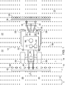
- Figure 1 shows a top view of a field 10 on which an agricultural machine 12, comprising a self-propelled vehicle and work units connected thereto, is operating.
- plants 14 On the field 10, plants 14 have been planted or sown during a previous work step.
- the plants 14 are planted in a rectangular pattern with a first transverse distance x in a first (in Figure 1 and 2 horizontal) direction 16 between adjacent rows (measured in the direction extending transversely to the first direction 16) and a second transverse distance y in a second (in Figure 1 and 2 vertical) direction 18 between adjacent rows (measured in the direction extending transversely to the second direction 18).
- the distances x and y are different, and x can be half of y.
- x can be 19.05 cm (7.5 inches) and y can be 38.1 cm (15 inches).
- Directions 16, 18 are shown as orthogonal, but could alternatively include an angle different from 90 degrees.
- the plants 14 can be sown or planted in any useful manner, like based on a positioning system (for example, GPS) receiver or using local sensors on the seeding or planting machine.
- a positioning system for example, GPS
- US 20170071124 A1 the contents of which are incorporated herein by reference.
- the plants 14 are planted on the field 10 in rows, which have a lateral distance with respect to the forward direction v of the agricultural machine 12 that depends on the driving direction of the machine 12.
- the lateral distance between adjacent rows is x
- the lateral distance between adjacent rows is y
- Tramlines 20 and 22 can be provided on the field 10, i.e. areas between rows without plants 14, to enable the agricultural machine 12 to drive over the field 10 without damaging plants 14.
- tramlines can be provided as described in patent applications US 62/669,018 (dated 9 May 2018 , attorney docket number P28021-US-PRO) and US 16/298,689 (dated 11 March 2019 , attorney docket number P28021-US-ORD), the contents of each of which are incorporated herein by reference.
- the agricultural machine 12 is shown as a tractor with a chassis 24, steerable front wheels 26 and driven rear wheels 28.
- a first tool carrier 36 is mounted by means of a three-point hitch 46 with an upper link 30 and lower links 32 connected to arms 34 supporting the first tool carrier 36.
- a second tool carrier 42 is mounted by means of a front hitch 40. Both hitches 40, 46 can be moved in a vertical direction to lift the tool carriers 36, 42 into an inoperative position for example during turning in the headland.
- an antenna 48 for receiving signals of a positioning system like GPS, Galileo or Glonass is mounted on the roof of a cab of the agricultural machine 12 .
- the signals provided by the antenna 48 are fed to an electronic control unit 50 which is connected to a memory 52 storing a map of the field 10 including information about the position of the plants 14 and the tramlines 20, 22 and controlling an automatic steering system 60 to steer the agricultural machine 12 along the first direction 16 or second direction 18.
- automatic steering of agricultural machine 12 could be performed with a camera- or laser-based steering system detecting the plants 14 and/or tramlines 20, 22.
- an operator could steer the agricultural machine 12 along the first direction 16 or second direction 18 with the wheels 26, 28 in the tramlines 20, 22.
- the first tool carrier 36 supports a first set of work units 38 which are suited for mechanical and/or chemical weed control and/or for providing the plants 14 with nutrients and/or a plant protection product.
- the work units 38 of the first set are spaced with the lateral distances between adjacent work units corresponding to the first distance x and are positioned, during operation of the agricultural machine 12 in the first direction 16, as shown in Figure 1 , between adjacent rows, which extend in the first direction.
- the second tool carrier 42 supports a second set of work units 44 which are suited for mechanical and/or chemical weed control and/or for providing the plants 14 with nutrients and/or a plant protection product.
- the work units 44 of the second set are spaced with the lateral distances between adjacent work units corresponding to the second distance y.
- the second tool carrier 42 with the second set of work units 44 is brought into an inoperative position by the front hitch 40, as indicated in Figure 1 with the broken lines, since the second set of work units 44 is not required when the agricultural machine 12 moves in the first direction 16.
- the actuation of the front hitch 40 can be performed by the operator of machine 12 or automatically based upon signals from antenna 48 indicating the direction of machine 12.
- the second tool carrier 42 with the second set of work units 44 is brought into an operative position by the front hitch 40, as indicated in Figure 2 , since the second set of work units 44 is needed to cover these parts of the field 10 when the agricultural machine 12 moves in the second direction 18.
- the actuation of the front hitch 40 can be performed by the operator of machine 12 or automatically based upon signals from antenna 48 indicating the direction of machine 12.
- the same machine 12 can be used to perform cultivating operations on the field 10 in both directions 16, 18, with the only change being to move the second set of work units 44 into the inoperative position when working in the first direction 16 and moving the second set of work units into the operative position when working in the second direction 18.
- Figure 3 shows an embodiment of the first set of work units 38.
- a supporting frame 54 is connected by a bracket 56 to the first tool carrier 36 and supported on a wheel 58.
- the frame 54 carries two or three ground-engaging hoes 62, located laterally between adjacent rows of plants 14.
- Figure 4 shows an embodiment of the second set of work units 44.
- a supporting frame 54 is connected by a bracket 56 to the second tool carrier 42 and supported on a wheel 58.
- the frame 54 carries one ground-engaging hoe 62, located laterally between adjacent rows of plants 14, and covering the ground that, when driving in the second direction 18, cannot be hoed by the work units 38 of the first set of work units 38.
- Figure 5 indicates which parts of the ground are cultivated with the work units 38 of the first set of work units 38, indicated as “rear cultivated", since the first tool carrier 36 is mounted at the rear of agricultural machine 12, and with the work units 44 of the second set of work units 44, indicated as "front cultivated", since the second tool carrier 42 is mounted at the front of agricultural machine 12.
Abstract
Description
- The present disclosure relates generally to agricultural machines. More particularly it relates to a method and a machine for providing plant cultivation measures on a field, like removing weeds or applying nutrients or herbicides.
- Over the last decades, yield increases have been among others a function of increasing seed populations in the field. In growing row crops like corn, for example, there is a trend towards higher populations in the field. Smaller row widths and equidistant plant distances in smaller row widths are likely to come. For example,
EP 2227932 A1 mentions a twin-row planting with lateral distances of 19 and 38 cm between adjacent rows and alternating seed positions. In certain applications, this may help maximize the land use, optimize moisture conservation, and capture sunlight but enable also new agronomic degrees of freedom in post-emergence crop protection and nutrient application. As a result of these denser populations, corn plants in the future may be smaller than they have been in the past, due to the smaller available space on the field. - Seeds may be planted in quadratic or regular patterns, which enables certain crop protection and nutrient practices (e.g., mechanical hoeing and fertilizing) in quadratic patterns or clusters. While hoeing and fertilizing operations on plants standing in a square pattern can be done with the same machine in a first direction and in a second, transverse direction, this is not possible to perform with the same machine if the plant pattern is not square-shaped, as it might be required in the future for optimizing plant growth results, as mentioned above. The respective work units of an implement for hoeing or dispensing fertilizer or herbicides need to be located between adjacent rows of plants. If the spacing between adjacent rows is dependent on the working direction, as it is the case if the plants are not in a square pattern, this means that the work units need to be shifted laterally to adapt to the respective row spacing or that different implements are needed for the two different work directions on a field. Both options have disadvantages.
- According to a first aspect, a cultivation operation may be performed on a field on which plants are planted in a regular, non-square pattern with plants in parallel, linear rows with a first transverse distance between adjacent rows in a first direction being smaller than a second transverse distance between adjacent rows in a second direction different from the first direction. The method may include operating an agricultural machine over the field in the first direction, the machine connected to a first set of work units with lateral distances between adjacent work units of the first set of work units corresponding to the first distance, with the work units of the first set of the work units positioned between adjacent rows that extend in the first direction and interact with at least one the ground between adjacent rows and the plants of at least one of the rows adjacent the respective work unit and operating the agricultural machine over the field in the second direction, with the work units of the first set of the work units positioned between adjacent rows that extend in the second direction and interact with at least one the ground between adjacent rows and the plants of at least one of the rows adjacent the respective work unit. Due to the first distance between adjacent rows in the first direction being smaller than second distance between adjacent rows in the second direction, areas between adjacent rows in the second direction cannot be treated with the work units of the first set of the work units during operation of the agricultural machine in the second direction. The agricultural machine may be connected to a second set of work units which are inoperative during operation of the agricultural machine in the first direction and operative during operation of the agricultural machine in the second direction to cover the areas between adjacent rows which cannot be treated with the work units of the first set of the work units during operation of the agricultural machine in the second direction.
- The work units of the first set of work units can be mounted to a first transverse tool carrier and the work units of the second set of work units can be mounted to a second transverse tool carrier. The second tool carrier can be moved into an operative position during operation of the agricultural machine in the second direction and into an inoperative position during operation of the agricultural machine in the first direction.
- The first tool carrier can be mounted at the rear of the agricultural machine and the second tool carrier can be mounted at the front of the agricultural machine.
- The work units can be adapted to at least one of: hoeing the ground between adjacent rows, fertilizing the plants of at least one of the rows adjacent the respective work unit and supplying a plant protection product, like a herbicide, pesticide or a fungicide to the plants of at least one of the adjacent rows.
- The work units of the first set of work units may supply fertilizer to the ground adjacent the plants. This means that when the agricultural machine drives along the first direction, fertilizer bands are laid down between the adjacent rows. When the agricultural machine however drives in the second direction, fertilizer bands are also laid down between the adjacent rows, but no fertilizer is provided where no plants are located, since this area is not covered by the work units of the first set of work units.
- The first distance can be half of the second distance and the first and second direction can be orthogonal, although other angles between the first and second direction are possible, for example to achieve a diamond-shaped pattern.
- According to another aspect, an agricultural machine may perform a cultivation operation on a field on which plants are planted in a regular, non-square pattern with plants in parallel, linear rows with a first transverse distance between adjacent rows in a first direction being smaller than a second transverse distance between adjacent rows in a second direction different from the first direction is provided. The agricultural machine may be connected to a first set of work units with lateral distances between adjacent work units of the first set of work units corresponding to the first distance, with the work units of the first set of the work units being positionable between adjacent rows that extend in the first direction and adapted to interact with at least one the ground between adjacent rows and the plants of at least one of the rows adjacent the respective work unit during operation of the agricultural operation in the first direction, while the work units of the first set of the work units are positionable between adjacent rows that extend in the second direction and adapted to interact with at least one the ground between adjacent rows and the plants of at least one of the rows adjacent the respective work unit during operation of the agricultural operation in the second direction. The agricultural machine may be connected to a second set of work units which are adapted to be inoperative during operation of the agricultural machine in the first direction and adapted to be operative during operation of the agricultural machine in the second direction to cover the areas between adjacent rows which cannot be treated with the work units of the first set of the work units during operation of the agricultural machine in the second direction.
- The above and other features will become apparent from the following description and accompanying drawings.
- The detailed description of the drawings refers to the accompanying figures in which:
-
Figure 1 is a schematic top view of an agricultural machine during a cultivation operation on a field working in a first direction; -
Figure 2 is a schematic top view of the agricultural machine ofFigure 1 during a cultivation operation on a field working in a second direction; -
Figure 3 is a top view of a number of first work units of the agricultural machine ofFigures 1 and2 ; -
Figure 4 is a top view of a number of second work units of the agricultural machine ofFigure 1 and2 ; -
Figure 5 is a schematic view of areas of the field covered during a hoeing operation with the agricultural machine ofFigures 1 and2 ; and -
Figure 6 is a schematic view of areas of the field covered during a fertilizing operation with the agricultural machine ofFigures 1 and2 . - Like reference numerals are used to indicate like elements throughout the several figures.
- At least one example embodiment of the subject matter of this disclosure is understood by referring to
Figures 1 through 6 of the drawings. -
Figure 1 shows a top view of afield 10 on which anagricultural machine 12, comprising a self-propelled vehicle and work units connected thereto, is operating. On thefield 10,plants 14 have been planted or sown during a previous work step. Theplants 14 are planted in a rectangular pattern with a first transverse distance x in a first (inFigure 1 and2 horizontal)direction 16 between adjacent rows (measured in the direction extending transversely to the first direction 16) and a second transverse distance y in a second (inFigure 1 and2 vertical)direction 18 between adjacent rows (measured in the direction extending transversely to the second direction 18). The distances x and y are different, and x can be half of y. In a possible embodiment, x can be 19.05 cm (7.5 inches) and y can be 38.1 cm (15 inches).Directions plants 14 can be sown or planted in any useful manner, like based on a positioning system (for example, GPS) receiver or using local sensors on the seeding or planting machine. In this respect, reference is made to the prior art (EP 1415523 A1 ,US 20170071124 A1 ), the contents of which are incorporated herein by reference. - Hence, the
plants 14 are planted on thefield 10 in rows, which have a lateral distance with respect to the forward direction v of theagricultural machine 12 that depends on the driving direction of themachine 12. If the machine drives in thefirst direction 16, the lateral distance between adjacent rows (transverse to the first (forward) direction 16) is x and if the machine drives in thesecond direction 18, the lateral distance between adjacent rows (transverse to the second (forward) direction) is y, wherein in the embodiment shown, x is smaller than y.Tramlines field 10, i.e. areas between rows withoutplants 14, to enable theagricultural machine 12 to drive over thefield 10 withoutdamaging plants 14. The tramlines can be provided as described in patent applicationsUS 62/669,018 (dated 9 May 2018 US 16/298,689 (dated 11 March 2019 - The
agricultural machine 12 is shown as a tractor with achassis 24, steerablefront wheels 26 and drivenrear wheels 28. On the rear end of thechassis 24, afirst tool carrier 36 is mounted by means of a three-point hitch 46 with anupper link 30 andlower links 32 connected toarms 34 supporting thefirst tool carrier 36. On the front end of thechassis 24, asecond tool carrier 42 is mounted by means of afront hitch 40. Bothhitches tool carriers - On the roof of a cab of the
agricultural machine 12 anantenna 48 for receiving signals of a positioning system like GPS, Galileo or Glonass is mounted. The signals provided by theantenna 48 are fed to anelectronic control unit 50 which is connected to amemory 52 storing a map of thefield 10 including information about the position of theplants 14 and thetramlines automatic steering system 60 to steer theagricultural machine 12 along thefirst direction 16 orsecond direction 18. Alternatively or additionally, automatic steering ofagricultural machine 12 could be performed with a camera- or laser-based steering system detecting theplants 14 and/ortramlines agricultural machine 12 along thefirst direction 16 orsecond direction 18 with thewheels tramlines - The
first tool carrier 36 supports a first set ofwork units 38 which are suited for mechanical and/or chemical weed control and/or for providing theplants 14 with nutrients and/or a plant protection product. Thework units 38 of the first set are spaced with the lateral distances between adjacent work units corresponding to the first distance x and are positioned, during operation of theagricultural machine 12 in thefirst direction 16, as shown inFigure 1 , between adjacent rows, which extend in the first direction. - The
second tool carrier 42 supports a second set ofwork units 44 which are suited for mechanical and/or chemical weed control and/or for providing theplants 14 with nutrients and/or a plant protection product. Thework units 44 of the second set are spaced with the lateral distances between adjacent work units corresponding to the second distance y. - While working in the
first direction 16, thesecond tool carrier 42 with the second set ofwork units 44 is brought into an inoperative position by thefront hitch 40, as indicated inFigure 1 with the broken lines, since the second set ofwork units 44 is not required when theagricultural machine 12 moves in thefirst direction 16. The actuation of thefront hitch 40 can be performed by the operator ofmachine 12 or automatically based upon signals fromantenna 48 indicating the direction ofmachine 12. - Since the second distance y is larger than the first distance x, when the
machine 12 is driving in thesecond direction 18, areas between the rows would be uncovered by thework units 38, as can be seen inFigure 2 . Thus, thesecond tool carrier 42 with the second set ofwork units 44 is brought into an operative position by thefront hitch 40, as indicated inFigure 2 , since the second set ofwork units 44 is needed to cover these parts of thefield 10 when theagricultural machine 12 moves in thesecond direction 18. The actuation of thefront hitch 40 can be performed by the operator ofmachine 12 or automatically based upon signals fromantenna 48 indicating the direction ofmachine 12. Thus, thesame machine 12 can be used to perform cultivating operations on thefield 10 in bothdirections work units 44 into the inoperative position when working in thefirst direction 16 and moving the second set of work units into the operative position when working in thesecond direction 18. -
Figure 3 shows an embodiment of the first set ofwork units 38. A supportingframe 54 is connected by abracket 56 to thefirst tool carrier 36 and supported on awheel 58. Theframe 54 carries two or three ground-engaginghoes 62, located laterally between adjacent rows ofplants 14. -
Figure 4 shows an embodiment of the second set ofwork units 44. A supportingframe 54 is connected by abracket 56 to thesecond tool carrier 42 and supported on awheel 58. Theframe 54 carries one ground-engaginghoe 62, located laterally between adjacent rows ofplants 14, and covering the ground that, when driving in thesecond direction 18, cannot be hoed by thework units 38 of the first set ofwork units 38. -
Figure 5 indicates which parts of the ground are cultivated with thework units 38 of the first set ofwork units 38, indicated as "rear cultivated", since thefirst tool carrier 36 is mounted at the rear ofagricultural machine 12, and with thework units 44 of the second set ofwork units 44, indicated as "front cultivated", since thesecond tool carrier 42 is mounted at the front ofagricultural machine 12. - It would be possible to provide the
work units 38 of the first set ofwork units 38 withfertilizer dispensers 64, as shown inFigure 3 . In this case, the fertilizer would only be distributed by thework units 38, yielding the distribution indicated inFigure 6 . The second set ofwork units 44 does not need to be provided withfertilizer dispensers 64, since they would cover areas withoutplants 14. - While the present disclosure has been illustrated and described in detail in the drawings and foregoing description, such illustration and description is not restrictive in character, it being understood that illustrative embodiment(s) have been shown and described and that all changes and modifications that come within the spirit of the present disclosure are desired to be protected. Alternative embodiments of the present disclosure may not include all of the features described yet still benefit from at least some of the advantages of such features. Those of ordinary skill in the art may devise their own implementations that incorporate one or more of the features of the present disclosure and fall within the spirit and scope of the appended claims.
Claims (12)
- A method of performing a cultivation operation on a field on which plants are planted in a regular, non-square pattern with the plants in parallel, linear rows with a first transverse distance between adjacent rows in a first direction being smaller than a second transverse distance between adjacent rows in a second direction different from the first direction, with the following steps:operating an agricultural machine over the field in the first direction, the machine connected to a first set of work units with lateral distances between adjacent work units of the first set of work units corresponding to the first distance, the work units of the first set of work units positioned between adjacent rows that extend in the first direction and interacting with at least one of the ground between adjacent rows and the plants of at least one of the adjacent rows; andoperating the agricultural machine over the field in the second direction, the work units of the first set of the work units positioned between adjacent rows that extend in the second direction and interacting with at least one of the ground between adjacent rows and the plants of at least one of the adjacent rows;wherein due to the first distance between adjacent rows in the first direction being smaller than the second distance between adjacent rows in the second direction, areas between adjacent rows in the second direction cannot be treated with the work units of the first set of the work units during operation of the agricultural machine in the second direction; andwherein the agricultural machine is connected to a second set of work units which are inoperative during operation of the agricultural machine in the first direction and operative during operation of the agricultural machine in the second direction to cover the areas between adjacent rows which cannot be treated with the work units of the first set of the work units during operation of the agricultural machine in the second direction.
- The method of claim 1, wherein the work units of the first set of work units are mounted to a first transverse tool carrier and the work units of the second set of work units are mounted to a second transverse tool carrier, the second tool carrier moved into an operative position during operation of the agricultural machine in the second direction and into an inoperative position during operation of the agricultural machine in the first direction.
- The method of claim 2, wherein the first tool carrier is mounted at the rear of the agricultural machine and the second tool carrier is mounted at the front of the agricultural machine.
- The method of claim 1, wherein the work units of the first set of work units and the work units of the second set of work units are each at least one of hoeing the ground between adjacent rows, fertilizing the plants of at least one of the rows adjacent the respective work unit, and supplying a plant protection product to the plants of at least one of the adjacent rows.
- The method of claim 4, wherein only the work units of the first set of work units are supplying fertilizer to the ground between adjacent rows the plants.
- The method of claim 1, wherein the first distance is half of the second distance and the first and second direction are orthogonal.
- An agricultural machine for performing a cultivation operation on a field on which plants are planted in a regular, non-square pattern with the plants in parallel, linear rows with a first transverse distance between adjacent rows in a first direction being smaller than a second transverse distance between adjacent rows in a second direction different from the first direction, the agricultural machine comprising:a first set of work units with lateral distances between adjacent work units of the first set of work units corresponding to the first distance, the work units of the first set of the work units positionable between adjacent rows that extend in the first direction and adapted to interact with at least one of the ground between adjacent rows and the plants of at least one of the adjacent rows during operation of the agricultural machine in the first direction, the work units of the first set of the work units positionable between adjacent rows that extend in the second direction and adapted to interact with at least one of the ground between adjacent rows and the plants of at least one of the adjacent rows during operation of the agricultural machine in the second direction; anda second set of work units which are adapted to be inoperative during operation of the agricultural machine in the first direction and adapted to be operative during operation of the agricultural machine in the second direction to cover the areas between adjacent rows which cannot be treated with the work units of the first set of the work units during operation of the agricultural machine in the second direction.
- The agricultural machine of claim 7, wherein the work units of the first set of work units are mounted to a first transverse tool carrier and the work units of the second set of work units are mounted to a second transverse tool carrier, the second tool carrier adapted to be moved into an operative position during operation of the agricultural machine in the second direction and into an inoperative position during operation of the agricultural machine in the first direction.
- The agricultural machine of claim 8, wherein the first tool carrier is mounted at the rear of the agricultural machine and the second tool carrier is mounted at the front of the agricultural machine.
- The agricultural machine of claim 7, wherein the work units are adapted to perform at least one of the following: hoe the ground between adjacent rows, fertilize the plants of at least one of the adjacent rows, and supply a plant protection product to the plants of at least one of the adjacent rows.
- The agricultural machine of claim 10, wherein only the work units of the first set of work units are adapted to supply fertilizer to the ground between adjacent rows.
- The agricultural machine of claim 6, wherein the first distance is half of the second distance and the first and second direction are orthogonal.
Applications Claiming Priority (2)
| Application Number | Priority Date | Filing Date | Title |
|---|---|---|---|
| US201862671936P | 2018-05-15 | 2018-05-15 | |
| US16/356,649 US11134608B2 (en) | 2018-05-15 | 2019-03-18 | Method and machine for plant cultivation on a field |
Publications (2)
| Publication Number | Publication Date |
|---|---|
| EP3569045A1 true EP3569045A1 (en) | 2019-11-20 |
| EP3569045B1 EP3569045B1 (en) | 2021-03-03 |
Family
ID=66483918
Family Applications (1)
| Application Number | Title | Priority Date | Filing Date |
|---|---|---|---|
| EP19173801.2A Active EP3569045B1 (en) | 2018-05-15 | 2019-05-10 | Method and machine for plant cultivation on a field |
Country Status (3)
| Country | Link |
|---|---|
| US (1) | US11134608B2 (en) |
| EP (1) | EP3569045B1 (en) |
| AU (1) | AU2019202627A1 (en) |
Cited By (1)
| Publication number | Priority date | Publication date | Assignee | Title |
|---|---|---|---|---|
| DE102020117911A1 (en) | 2020-07-07 | 2022-01-13 | Deere & Company | Method of growing plants in a regular pattern with site-adapted variation in plant density |
Citations (7)
| Publication number | Priority date | Publication date | Assignee | Title |
|---|---|---|---|---|
| DE68903856T3 (en) * | 1988-03-30 | 1998-04-16 | Lely Nv C Van Der | Mechanically driven tillage implement. |
| EP0916243A1 (en) * | 1997-11-13 | 1999-05-19 | Amazonen-Werke H. Dreyer GmbH & Co. KG | Working device for targeted working across rows |
| EP1415523A1 (en) | 2002-11-02 | 2004-05-06 | Kverneland ASA | Sowing machine |
| DE102005010686A1 (en) * | 2004-03-16 | 2005-10-13 | Benninger, Johannes, Dipl.-Ing. | Agricultural planting of seedlings and seeds has planting units coupled to distance measuring units and a controller |
| EP2227932A1 (en) | 2009-03-11 | 2010-09-15 | Deere & Company | Agricultural seeding machine |
| DE102011078286A1 (en) * | 2011-06-29 | 2013-01-03 | Robert Bosch Gmbh | Method for mechanical machining of objects arranged in rows, particularly near ground, such as agricultural crops and forestry crops, involves sensing number of objects in row, and processing of number of sensed objects in row |
| US20170071124A1 (en) | 2015-09-14 | 2017-03-16 | Deere & Company | Method for planting seeds or plants and a corresponding machine |
Family Cites Families (15)
| Publication number | Priority date | Publication date | Assignee | Title |
|---|---|---|---|---|
| US4248310A (en) * | 1979-06-28 | 1981-02-03 | Mcwilliams William R | Skip row cultivators |
| DE29705991U1 (en) | 1997-04-03 | 1997-06-19 | Rau Gmbh Maschf | Device for dispensing particulate material |
| US6199000B1 (en) | 1998-07-15 | 2001-03-06 | Trimble Navigation Limited | Methods and apparatus for precision agriculture operations utilizing real time kinematic global positioning system systems |
| US7775167B2 (en) * | 2006-08-22 | 2010-08-17 | Monsanto Technology Llc | Custom planter and method of custom planting |
| US8234988B2 (en) | 2008-11-26 | 2012-08-07 | Ag Leader Technology | Seed dispenser control |
| US8322293B2 (en) * | 2009-05-06 | 2012-12-04 | Agco Corporation | Precision fertilizer placement |
| US9955625B2 (en) | 2010-07-27 | 2018-05-01 | Precision Planting Llc | Seeding control system and method |
| US8600629B2 (en) | 2011-07-28 | 2013-12-03 | Ag Leader Technology | Compensation method for planter shut off delay |
| US20150289442A1 (en) | 2014-04-09 | 2015-10-15 | Appareo Systems, Llc | Flexible seed metering disk |
| US10004175B1 (en) * | 2016-03-30 | 2018-06-26 | John A. Miller | Fertilizer application |
| EP3439450A4 (en) * | 2016-04-07 | 2019-12-25 | Mollick, Peter J. | System for connecting implement to mobile machinery |
| DE102016207510A1 (en) | 2016-05-02 | 2017-11-02 | Deere & Company | Pneumatic seed drill |
| US10806068B2 (en) * | 2016-05-06 | 2020-10-20 | Cnh Industrial Canada, Ltd. | Double-shoot disc drill using two distinct staggered row units |
| US10375891B2 (en) * | 2016-07-05 | 2019-08-13 | Charles H. Martin | Agricultural device |
| US11033921B2 (en) * | 2017-10-30 | 2021-06-15 | Deere & Company | System for spraying plants with automated nozzle selection |
-
2019
- 2019-03-18 US US16/356,649 patent/US11134608B2/en active Active
- 2019-04-16 AU AU2019202627A patent/AU2019202627A1/en active Pending
- 2019-05-10 EP EP19173801.2A patent/EP3569045B1/en active Active
Patent Citations (7)
| Publication number | Priority date | Publication date | Assignee | Title |
|---|---|---|---|---|
| DE68903856T3 (en) * | 1988-03-30 | 1998-04-16 | Lely Nv C Van Der | Mechanically driven tillage implement. |
| EP0916243A1 (en) * | 1997-11-13 | 1999-05-19 | Amazonen-Werke H. Dreyer GmbH & Co. KG | Working device for targeted working across rows |
| EP1415523A1 (en) | 2002-11-02 | 2004-05-06 | Kverneland ASA | Sowing machine |
| DE102005010686A1 (en) * | 2004-03-16 | 2005-10-13 | Benninger, Johannes, Dipl.-Ing. | Agricultural planting of seedlings and seeds has planting units coupled to distance measuring units and a controller |
| EP2227932A1 (en) | 2009-03-11 | 2010-09-15 | Deere & Company | Agricultural seeding machine |
| DE102011078286A1 (en) * | 2011-06-29 | 2013-01-03 | Robert Bosch Gmbh | Method for mechanical machining of objects arranged in rows, particularly near ground, such as agricultural crops and forestry crops, involves sensing number of objects in row, and processing of number of sensed objects in row |
| US20170071124A1 (en) | 2015-09-14 | 2017-03-16 | Deere & Company | Method for planting seeds or plants and a corresponding machine |
Cited By (1)
| Publication number | Priority date | Publication date | Assignee | Title |
|---|---|---|---|---|
| DE102020117911A1 (en) | 2020-07-07 | 2022-01-13 | Deere & Company | Method of growing plants in a regular pattern with site-adapted variation in plant density |
Also Published As
| Publication number | Publication date |
|---|---|
| US11134608B2 (en) | 2021-10-05 |
| US20190350128A1 (en) | 2019-11-21 |
| AU2019202627A1 (en) | 2019-12-05 |
| EP3569045B1 (en) | 2021-03-03 |
Similar Documents
| Publication | Publication Date | Title |
|---|---|---|
| EP3278645B1 (en) | Method for optimizing an operating parameter of a machine for the application of agricultural material to a field and corresponding machine | |
| EP3476216B1 (en) | Method for treating plants with respect to estimated root zones | |
| US9848528B2 (en) | Method for planting seeds or plants and a corresponding machine | |
| US11033921B2 (en) | System for spraying plants with automated nozzle selection | |
| US9445538B2 (en) | Apparatus and method for no-till inter-row simultaneous application of herbicide and fertilizer, soil preparation, and seeding of a cover crop in a standing crop | |
| US9456539B2 (en) | Apparatus and method for no-till inter-row simultaneous application of herbicide and fertilizer, soil preparation, and seeding of a cover crop in a standing crop | |
| EP3571913B1 (en) | Method for performing tasks in a pattern planted | |
| US7591226B2 (en) | Automatic path generation for tramlines | |
| JPS6043317A (en) | Soil maintenance intercropping method and apparatus | |
| EP3243371B1 (en) | Automated farming systems | |
| EP3243370B1 (en) | Automated farming systems | |
| EP3569045B1 (en) | Method and machine for plant cultivation on a field | |
| Tillett et al. | Increasing work rate in vision guided precision banded operations | |
| US20150216117A1 (en) | Method for producing marking strips using at least two seeders moving simultaneously in a field | |
| US20220007564A1 (en) | Method for Performing an Agricultural Task | |
| Santhosh et al. | Iot based agriculture using agribot | |
| Berglund et al. | Guidance and automated steering drive resurgence in precision farming | |
| Nare et al. | Mechanization in potato cultivation | |
| Tuğrul | Mechanization in Sugar Beet Cultivation | |
| JP2021023223A (en) | Work support device, work support system, work-related information management device, and work-related information management system | |
| AU2022323503A1 (en) | Device and method for cultivating an agricultural area | |
| CZ2020614A3 (en) | Working unit for agricultural machine | |
| Godwin | Advances in labour and machinery management | |
| Stalcup | Pinpoint accuracy | |
| JPH06292407A (en) | Moving working apparatus |
Legal Events
| Date | Code | Title | Description |
|---|---|---|---|
| PUAI | Public reference made under article 153(3) epc to a published international application that has entered the european phase |
Free format text: ORIGINAL CODE: 0009012 |
|
| STAA | Information on the status of an ep patent application or granted ep patent |
Free format text: STATUS: THE APPLICATION HAS BEEN PUBLISHED |
|
| AK | Designated contracting states |
Kind code of ref document: A1 Designated state(s): AL AT BE BG CH CY CZ DE DK EE ES FI FR GB GR HR HU IE IS IT LI LT LU LV MC MK MT NL NO PL PT RO RS SE SI SK SM TR |
|
| AX | Request for extension of the european patent |
Extension state: BA ME |
|
| STAA | Information on the status of an ep patent application or granted ep patent |
Free format text: STATUS: REQUEST FOR EXAMINATION WAS MADE |
|
| 17P | Request for examination filed |
Effective date: 20200520 |
|
| RBV | Designated contracting states (corrected) |
Designated state(s): AL AT BE BG CH CY CZ DE DK EE ES FI FR GB GR HR HU IE IS IT LI LT LU LV MC MK MT NL NO PL PT RO RS SE SI SK SM TR |
|
| GRAP | Despatch of communication of intention to grant a patent |
Free format text: ORIGINAL CODE: EPIDOSNIGR1 |
|
| STAA | Information on the status of an ep patent application or granted ep patent |
Free format text: STATUS: GRANT OF PATENT IS INTENDED |
|
| INTG | Intention to grant announced |
Effective date: 20201026 |
|
| GRAS | Grant fee paid |
Free format text: ORIGINAL CODE: EPIDOSNIGR3 |
|
| STAA | Information on the status of an ep patent application or granted ep patent |
Free format text: STATUS: GRANT OF PATENT IS INTENDED |
|
| GRAA | (expected) grant |
Free format text: ORIGINAL CODE: 0009210 |
|
| STAA | Information on the status of an ep patent application or granted ep patent |
Free format text: STATUS: THE PATENT HAS BEEN GRANTED |
|
| AK | Designated contracting states |
Kind code of ref document: B1 Designated state(s): AL AT BE BG CH CY CZ DE DK EE ES FI FR GB GR HR HU IE IS IT LI LT LU LV MC MK MT NL NO PL PT RO RS SE SI SK SM TR |
|
| REG | Reference to a national code |
Ref country code: GB Ref legal event code: FG4D |
|
| REG | Reference to a national code |
Ref country code: CH Ref legal event code: EP Ref country code: AT Ref legal event code: REF Ref document number: 1366149 Country of ref document: AT Kind code of ref document: T Effective date: 20210315 |
|
| REG | Reference to a national code |
Ref country code: DE Ref legal event code: R096 Ref document number: 602019002878 Country of ref document: DE |
|
| REG | Reference to a national code |
Ref country code: IE Ref legal event code: FG4D |
|
| REG | Reference to a national code |
Ref country code: LT Ref legal event code: MG9D |
|
| PG25 | Lapsed in a contracting state [announced via postgrant information from national office to epo] |
Ref country code: BG Free format text: LAPSE BECAUSE OF FAILURE TO SUBMIT A TRANSLATION OF THE DESCRIPTION OR TO PAY THE FEE WITHIN THE PRESCRIBED TIME-LIMIT Effective date: 20210603 Ref country code: GR Free format text: LAPSE BECAUSE OF FAILURE TO SUBMIT A TRANSLATION OF THE DESCRIPTION OR TO PAY THE FEE WITHIN THE PRESCRIBED TIME-LIMIT Effective date: 20210604 Ref country code: HR Free format text: LAPSE BECAUSE OF FAILURE TO SUBMIT A TRANSLATION OF THE DESCRIPTION OR TO PAY THE FEE WITHIN THE PRESCRIBED TIME-LIMIT Effective date: 20210303 Ref country code: FI Free format text: LAPSE BECAUSE OF FAILURE TO SUBMIT A TRANSLATION OF THE DESCRIPTION OR TO PAY THE FEE WITHIN THE PRESCRIBED TIME-LIMIT Effective date: 20210303 Ref country code: NO Free format text: LAPSE BECAUSE OF FAILURE TO SUBMIT A TRANSLATION OF THE DESCRIPTION OR TO PAY THE FEE WITHIN THE PRESCRIBED TIME-LIMIT Effective date: 20210603 Ref country code: LT Free format text: LAPSE BECAUSE OF FAILURE TO SUBMIT A TRANSLATION OF THE DESCRIPTION OR TO PAY THE FEE WITHIN THE PRESCRIBED TIME-LIMIT Effective date: 20210303 |
|
| REG | Reference to a national code |
Ref country code: NL Ref legal event code: MP Effective date: 20210303 |
|
| REG | Reference to a national code |
Ref country code: AT Ref legal event code: MK05 Ref document number: 1366149 Country of ref document: AT Kind code of ref document: T Effective date: 20210303 |
|
| PG25 | Lapsed in a contracting state [announced via postgrant information from national office to epo] |
Ref country code: SE Free format text: LAPSE BECAUSE OF FAILURE TO SUBMIT A TRANSLATION OF THE DESCRIPTION OR TO PAY THE FEE WITHIN THE PRESCRIBED TIME-LIMIT Effective date: 20210303 Ref country code: LV Free format text: LAPSE BECAUSE OF FAILURE TO SUBMIT A TRANSLATION OF THE DESCRIPTION OR TO PAY THE FEE WITHIN THE PRESCRIBED TIME-LIMIT Effective date: 20210303 Ref country code: PL Free format text: LAPSE BECAUSE OF FAILURE TO SUBMIT A TRANSLATION OF THE DESCRIPTION OR TO PAY THE FEE WITHIN THE PRESCRIBED TIME-LIMIT Effective date: 20210303 Ref country code: RS Free format text: LAPSE BECAUSE OF FAILURE TO SUBMIT A TRANSLATION OF THE DESCRIPTION OR TO PAY THE FEE WITHIN THE PRESCRIBED TIME-LIMIT Effective date: 20210303 |
|
| PG25 | Lapsed in a contracting state [announced via postgrant information from national office to epo] |
Ref country code: NL Free format text: LAPSE BECAUSE OF FAILURE TO SUBMIT A TRANSLATION OF THE DESCRIPTION OR TO PAY THE FEE WITHIN THE PRESCRIBED TIME-LIMIT Effective date: 20210303 |
|
| PG25 | Lapsed in a contracting state [announced via postgrant information from national office to epo] |
Ref country code: CZ Free format text: LAPSE BECAUSE OF FAILURE TO SUBMIT A TRANSLATION OF THE DESCRIPTION OR TO PAY THE FEE WITHIN THE PRESCRIBED TIME-LIMIT Effective date: 20210303 Ref country code: EE Free format text: LAPSE BECAUSE OF FAILURE TO SUBMIT A TRANSLATION OF THE DESCRIPTION OR TO PAY THE FEE WITHIN THE PRESCRIBED TIME-LIMIT Effective date: 20210303 Ref country code: SM Free format text: LAPSE BECAUSE OF FAILURE TO SUBMIT A TRANSLATION OF THE DESCRIPTION OR TO PAY THE FEE WITHIN THE PRESCRIBED TIME-LIMIT Effective date: 20210303 Ref country code: AT Free format text: LAPSE BECAUSE OF FAILURE TO SUBMIT A TRANSLATION OF THE DESCRIPTION OR TO PAY THE FEE WITHIN THE PRESCRIBED TIME-LIMIT Effective date: 20210303 |
|
| PG25 | Lapsed in a contracting state [announced via postgrant information from national office to epo] |
Ref country code: IS Free format text: LAPSE BECAUSE OF FAILURE TO SUBMIT A TRANSLATION OF THE DESCRIPTION OR TO PAY THE FEE WITHIN THE PRESCRIBED TIME-LIMIT Effective date: 20210703 Ref country code: PT Free format text: LAPSE BECAUSE OF FAILURE TO SUBMIT A TRANSLATION OF THE DESCRIPTION OR TO PAY THE FEE WITHIN THE PRESCRIBED TIME-LIMIT Effective date: 20210705 Ref country code: RO Free format text: LAPSE BECAUSE OF FAILURE TO SUBMIT A TRANSLATION OF THE DESCRIPTION OR TO PAY THE FEE WITHIN THE PRESCRIBED TIME-LIMIT Effective date: 20210303 Ref country code: SK Free format text: LAPSE BECAUSE OF FAILURE TO SUBMIT A TRANSLATION OF THE DESCRIPTION OR TO PAY THE FEE WITHIN THE PRESCRIBED TIME-LIMIT Effective date: 20210303 |
|
| REG | Reference to a national code |
Ref country code: DE Ref legal event code: R097 Ref document number: 602019002878 Country of ref document: DE |
|
| PLBE | No opposition filed within time limit |
Free format text: ORIGINAL CODE: 0009261 |
|
| STAA | Information on the status of an ep patent application or granted ep patent |
Free format text: STATUS: NO OPPOSITION FILED WITHIN TIME LIMIT |
|
| PG25 | Lapsed in a contracting state [announced via postgrant information from national office to epo] |
Ref country code: ES Free format text: LAPSE BECAUSE OF FAILURE TO SUBMIT A TRANSLATION OF THE DESCRIPTION OR TO PAY THE FEE WITHIN THE PRESCRIBED TIME-LIMIT Effective date: 20210303 Ref country code: AL Free format text: LAPSE BECAUSE OF FAILURE TO SUBMIT A TRANSLATION OF THE DESCRIPTION OR TO PAY THE FEE WITHIN THE PRESCRIBED TIME-LIMIT Effective date: 20210303 Ref country code: DK Free format text: LAPSE BECAUSE OF FAILURE TO SUBMIT A TRANSLATION OF THE DESCRIPTION OR TO PAY THE FEE WITHIN THE PRESCRIBED TIME-LIMIT Effective date: 20210303 Ref country code: LU Free format text: LAPSE BECAUSE OF NON-PAYMENT OF DUE FEES Effective date: 20210510 Ref country code: MC Free format text: LAPSE BECAUSE OF FAILURE TO SUBMIT A TRANSLATION OF THE DESCRIPTION OR TO PAY THE FEE WITHIN THE PRESCRIBED TIME-LIMIT Effective date: 20210303 |
|
| 26N | No opposition filed |
Effective date: 20211206 |
|
| REG | Reference to a national code |
Ref country code: BE Ref legal event code: MM Effective date: 20210531 |
|
| PG25 | Lapsed in a contracting state [announced via postgrant information from national office to epo] |
Ref country code: SI Free format text: LAPSE BECAUSE OF FAILURE TO SUBMIT A TRANSLATION OF THE DESCRIPTION OR TO PAY THE FEE WITHIN THE PRESCRIBED TIME-LIMIT Effective date: 20210303 |
|
| PG25 | Lapsed in a contracting state [announced via postgrant information from national office to epo] |
Ref country code: IT Free format text: LAPSE BECAUSE OF FAILURE TO SUBMIT A TRANSLATION OF THE DESCRIPTION OR TO PAY THE FEE WITHIN THE PRESCRIBED TIME-LIMIT Effective date: 20210303 Ref country code: IE Free format text: LAPSE BECAUSE OF NON-PAYMENT OF DUE FEES Effective date: 20210510 |
|
| PG25 | Lapsed in a contracting state [announced via postgrant information from national office to epo] |
Ref country code: IS Free format text: LAPSE BECAUSE OF FAILURE TO SUBMIT A TRANSLATION OF THE DESCRIPTION OR TO PAY THE FEE WITHIN THE PRESCRIBED TIME-LIMIT Effective date: 20210703 |
|
| PG25 | Lapsed in a contracting state [announced via postgrant information from national office to epo] |
Ref country code: BE Free format text: LAPSE BECAUSE OF NON-PAYMENT OF DUE FEES Effective date: 20210531 |
|
| REG | Reference to a national code |
Ref country code: CH Ref legal event code: PL |
|
| PG25 | Lapsed in a contracting state [announced via postgrant information from national office to epo] |
Ref country code: LI Free format text: LAPSE BECAUSE OF NON-PAYMENT OF DUE FEES Effective date: 20220531 Ref country code: CH Free format text: LAPSE BECAUSE OF NON-PAYMENT OF DUE FEES Effective date: 20220531 |
|
| PG25 | Lapsed in a contracting state [announced via postgrant information from national office to epo] |
Ref country code: CY Free format text: LAPSE BECAUSE OF FAILURE TO SUBMIT A TRANSLATION OF THE DESCRIPTION OR TO PAY THE FEE WITHIN THE PRESCRIBED TIME-LIMIT Effective date: 20210303 |
|
| PG25 | Lapsed in a contracting state [announced via postgrant information from national office to epo] |
Ref country code: HU Free format text: LAPSE BECAUSE OF FAILURE TO SUBMIT A TRANSLATION OF THE DESCRIPTION OR TO PAY THE FEE WITHIN THE PRESCRIBED TIME-LIMIT; INVALID AB INITIO Effective date: 20190510 |
|
| PGFP | Annual fee paid to national office [announced via postgrant information from national office to epo] |
Ref country code: FR Payment date: 20230525 Year of fee payment: 5 Ref country code: DE Payment date: 20230419 Year of fee payment: 5 |
|
| PGFP | Annual fee paid to national office [announced via postgrant information from national office to epo] |
Ref country code: GB Payment date: 20230529 Year of fee payment: 5 |