EP2227932A1 - Agricultural seeding machine - Google Patents
Agricultural seeding machine Download PDFInfo
- Publication number
- EP2227932A1 EP2227932A1 EP10155385A EP10155385A EP2227932A1 EP 2227932 A1 EP2227932 A1 EP 2227932A1 EP 10155385 A EP10155385 A EP 10155385A EP 10155385 A EP10155385 A EP 10155385A EP 2227932 A1 EP2227932 A1 EP 2227932A1
- Authority
- EP
- European Patent Office
- Prior art keywords
- seed
- reference signal
- sensor
- signal
- row
- Prior art date
- Legal status (The legal status is an assumption and is not a legal conclusion. Google has not performed a legal analysis and makes no representation as to the accuracy of the status listed.)
- Granted
Links
- 238000010899 nucleation Methods 0.000 title claims abstract description 29
- 230000009471 action Effects 0.000 claims abstract description 17
- 238000000034 method Methods 0.000 claims abstract description 9
- 239000002689 soil Substances 0.000 claims description 7
- 230000008859 change Effects 0.000 claims description 2
- 238000012545 processing Methods 0.000 description 11
- 230000007246 mechanism Effects 0.000 description 9
- 241000196324 Embryophyta Species 0.000 description 8
- 238000012544 monitoring process Methods 0.000 description 6
- 230000005540 biological transmission Effects 0.000 description 4
- 230000005484 gravity Effects 0.000 description 3
- 241001520881 Sporobolus Species 0.000 description 2
- 241000209149 Zea Species 0.000 description 2
- 235000005824 Zea mays ssp. parviglumis Nutrition 0.000 description 2
- 235000002017 Zea mays subsp mays Nutrition 0.000 description 2
- 238000004891 communication Methods 0.000 description 2
- 235000005822 corn Nutrition 0.000 description 2
- 238000010586 diagram Methods 0.000 description 2
- 230000002363 herbicidal effect Effects 0.000 description 2
- 239000004009 herbicide Substances 0.000 description 2
- 239000002917 insecticide Substances 0.000 description 2
- 230000003287 optical effect Effects 0.000 description 2
- 230000000737 periodic effect Effects 0.000 description 2
- 229920000742 Cotton Polymers 0.000 description 1
- 230000004075 alteration Effects 0.000 description 1
- 230000007274 generation of a signal involved in cell-cell signaling Effects 0.000 description 1
- 230000014759 maintenance of location Effects 0.000 description 1
- 238000012986 modification Methods 0.000 description 1
- 230000004048 modification Effects 0.000 description 1
- 230000002093 peripheral effect Effects 0.000 description 1
- 230000001360 synchronised effect Effects 0.000 description 1
- 238000012546 transfer Methods 0.000 description 1
Images


Classifications
-
- A—HUMAN NECESSITIES
- A01—AGRICULTURE; FORESTRY; ANIMAL HUSBANDRY; HUNTING; TRAPPING; FISHING
- A01C—PLANTING; SOWING; FERTILISING
- A01C7/00—Sowing
- A01C7/08—Broadcast seeders; Seeders depositing seeds in rows
- A01C7/10—Devices for adjusting the seed-box ; Regulation of machines for depositing quantities at intervals
- A01C7/102—Regulating or controlling the seed rate
-
- A—HUMAN NECESSITIES
- A01—AGRICULTURE; FORESTRY; ANIMAL HUSBANDRY; HUNTING; TRAPPING; FISHING
- A01C—PLANTING; SOWING; FERTILISING
- A01C21/00—Methods of fertilising, sowing or planting
- A01C21/005—Following a specific plan, e.g. pattern
-
- A—HUMAN NECESSITIES
- A01—AGRICULTURE; FORESTRY; ANIMAL HUSBANDRY; HUNTING; TRAPPING; FISHING
- A01C—PLANTING; SOWING; FERTILISING
- A01C7/00—Sowing
- A01C7/04—Single-grain seeders with or without suction devices
- A01C7/042—Single-grain seeders with or without suction devices using pneumatic means
- A01C7/044—Pneumatic seed wheels
- A01C7/046—Pneumatic seed wheels with perforated seeding discs
-
- A—HUMAN NECESSITIES
- A01—AGRICULTURE; FORESTRY; ANIMAL HUSBANDRY; HUNTING; TRAPPING; FISHING
- A01C—PLANTING; SOWING; FERTILISING
- A01C7/00—Sowing
- A01C7/08—Broadcast seeders; Seeders depositing seeds in rows
- A01C7/10—Devices for adjusting the seed-box ; Regulation of machines for depositing quantities at intervals
- A01C7/102—Regulating or controlling the seed rate
- A01C7/105—Seed sensors
-
- A—HUMAN NECESSITIES
- A01—AGRICULTURE; FORESTRY; ANIMAL HUSBANDRY; HUNTING; TRAPPING; FISHING
- A01C—PLANTING; SOWING; FERTILISING
- A01C19/00—Arrangements for driving working parts of fertilisers or seeders
- A01C19/02—Arrangements for driving working parts of fertilisers or seeders by a motor
-
- Y—GENERAL TAGGING OF NEW TECHNOLOGICAL DEVELOPMENTS; GENERAL TAGGING OF CROSS-SECTIONAL TECHNOLOGIES SPANNING OVER SEVERAL SECTIONS OF THE IPC; TECHNICAL SUBJECTS COVERED BY FORMER USPC CROSS-REFERENCE ART COLLECTIONS [XRACs] AND DIGESTS
- Y10—TECHNICAL SUBJECTS COVERED BY FORMER USPC
- Y10S—TECHNICAL SUBJECTS COVERED BY FORMER USPC CROSS-REFERENCE ART COLLECTIONS [XRACs] AND DIGESTS
- Y10S111/00—Planting
- Y10S111/90—Methods of planting seeds and miscellaneous compositions
-
- Y—GENERAL TAGGING OF NEW TECHNOLOGICAL DEVELOPMENTS; GENERAL TAGGING OF CROSS-SECTIONAL TECHNOLOGIES SPANNING OVER SEVERAL SECTIONS OF THE IPC; TECHNICAL SUBJECTS COVERED BY FORMER USPC CROSS-REFERENCE ART COLLECTIONS [XRACs] AND DIGESTS
- Y10—TECHNICAL SUBJECTS COVERED BY FORMER USPC
- Y10S—TECHNICAL SUBJECTS COVERED BY FORMER USPC CROSS-REFERENCE ART COLLECTIONS [XRACs] AND DIGESTS
- Y10S111/00—Planting
- Y10S111/903—Monitor
- Y10S111/904—Population control function
-
- Y—GENERAL TAGGING OF NEW TECHNOLOGICAL DEVELOPMENTS; GENERAL TAGGING OF CROSS-SECTIONAL TECHNOLOGIES SPANNING OVER SEVERAL SECTIONS OF THE IPC; TECHNICAL SUBJECTS COVERED BY FORMER USPC CROSS-REFERENCE ART COLLECTIONS [XRACs] AND DIGESTS
- Y10—TECHNICAL SUBJECTS COVERED BY FORMER USPC
- Y10S—TECHNICAL SUBJECTS COVERED BY FORMER USPC CROSS-REFERENCE ART COLLECTIONS [XRACs] AND DIGESTS
- Y10S111/00—Planting
- Y10S111/922—Variable drive mechanism
Definitions
- the present invention relates to a seeding machine comprising means for generating a reference signal, multiple row units, wherein at least one row unit having a seed metering device providing a metering action to a plurality of seeds, a drive for the seed metering device and a sensor adapted to sense a seed meter parameter.
- the invention further comprises a method for operating a seeding machine, including coordinating the placement of seed planted by multiple row units of a planter.
- An agricultural seeding machine such as a row crop planter or grain drill, places the seed at a desired depth within a plurality of parallel seed furrows formed in soil.
- a row crop planter a plurality of row units are typically ground driven using wheels, shafts, sprockets, transfer cases, chains and the like.
- Each row unit has a frame, which is movably coupled with a tool bar.
- the frame may carry a main seed hopper, herbicide hopper and insecticide hopper. If the granular herbicide and insecticide are used, the metering mechanisms associated therewith for the dispensing of the granular product into the seed furrow are relatively simple. On the other hand, mechanisms necessary to properly meter seeds at a predetermined rate and to place the seeds at a predetermined relative location and depth within the seed furrow are relatively complicated.
- the mechanisms associated with metering and placing of the seeds generally can be divided into a seed metering system and a seed placement system, which are in communication with each other.
- the seed metering system receives the seeds in a bulk manner from a seed hopper carried by the frame.
- Different types of seed metering systems can be used such as seed plates, finger plates, seed disks and belts.
- a seed disk metering system a seed disk is formed with a plurality of seed cells spaced about the periphery thereof. Seeds are moved into the seed cells with one or more seeds in each seed cell depending upon the size and configuration of the seed cell. A vacuum or positive pressure airflow may be used in conjunction with the seed disk to assist in movement and retention of the seeds in the seed cells.
- the seeds are singulated and discharged sequentially at a predetermined rate to the seed placement system.
- the seed placement system may be categorized as a gravity drop system or a power drop system.
- a seed tube has an inlet end, which is positioned below the seed metering system.
- the singulated seeds from the seed metering system merely drop into the seed tube and fall by way of gravitational force from a discharge end thereof into the seed furrow.
- the seed tube may be curved in a rearward manner to assist in directing the seed into the seed furrow.
- a seed placement system of the power drop variety generally can be classified as a seed conveyor belt drop, rotary valve drop, chain drop or air drop. These types of seed placement systems provide somewhat consistent placement of the seeds along a predetermined path at a desired spacing.
- twin-rows Planting of certain crops, such as corn, in what is called “twin-rows” is becoming increasingly popular. With twin-rows, two rows are closely spaced, for example, spaced apart 7.5 inches (19cm). The centers of the twin rows are spaced 30 inches (76cm) apart from the next set of twin rows. Within the twin rows, to maximize the yield, it is necessary to alternate the seeds in the twin rows to avoid crowding of the plants.
- one object of the invention is to provide an agricultural seeding machine having an automated system to synchronize or to assist the operator in synchronizing the seed placement between rows of seeds.
- a seeding machine of above mentioned type wherein the seed meter parameter relates to seed location in a furrow beneath the row unit and the sensor generating an index signal; and control means for receiving the index signal from the sensor and for receiving the reference signal, the control means determining a relationship between the index signal and the reference signal and the control means being operably coupled to the drive for altering the metering action of the seed metering device to establish a desired relationship between the index signal and the reference signal.
- the seeding machine has a plurality of row units and a processing circuit.
- Each of the row units has a seed metering device, a seed placement device and at least one sensor.
- the seed metering device includes a seed metering member or device such as a seed disk, plate, belt or finger plate providing a metering action to a plurality of seeds.
- the seed placement device receives the seeds sequentially from the seed metering device and delivers the seed to a seed furrow formed beneath the row unit.
- the sensor detects a parameter related to seed placement.
- the sensor may be a seed sensor positioned to detect the passage of seeds through the metering device, the seed placement device or in the furrow beneath the row unit.
- the sensor may also detect a feature of the metering member or the meter drive that relates to the seed placement.
- the processing circuit receives an index signal from each of the row unit sensors. In addition, the processing circuit receives a reference signal with periodic pulses. The processing circuit compares the index signals from the sensors of each row with the reference signal and determines a current relationship therebetween. For each row unit, there is a desired relationship between the reference signal and the index signal. If the actual relationship does not meet a desired relationship, the metering action of the row unit is altered to establish the desired relationship.
- the relationship between one row unit index signal and the reference signal will differ from the relationship between the other row unit index signal and the reference signal to produce the alternating, i.e. staggered pattern of plants among the two twin rows. Any other desired pattern between multiple rows can be produced beyond the above twin-row example.
- an agricultural system 10 including a tractor 12 and seeding machine 14.
- Seeding machine 14 is in the form of a row crop planter 14, but could be a grain drill.
- Tractor 12 provides the motive power for planter 14 and the mechanisms therein.
- a seed spacing monitoring/control system 16 is incorporated and used by the operator of tractor 12 to monitor the placing of seeds, from planter 14.
- FIG. 2-5 there is shown details of planter 14 that includes tool bar 20, seed supply 22, row units 24 each including a metering device 26 having a seed disk 28 with holes 30 therein.
- Metering devices 26 are either directly or indirectly connected to tool bar 20 that is in turn coupled with tractor 12. Seed is supplied to metering devices 26 by way of seed supply 22 and the seed is pooled over a portion of seed disk 28.
- Seed disk 28 is fluidly coupled to an airflow generator that supplies airflow to a cavity 46 and/or a cavity 48.
- the airflow generator may produce a positive or negative pressure depending on the configuration of planter 14. For ease of explanation the airflow will be understood to be a vacuum system.
- Airflow caused by the vacuum system is supplied to cavities 46 and/or 48 and thereby to one side of seed disk 28 causing air to flow through holes 30.
- the air flowing through holes 30 attracts seeds thereto as seed disk 28 is rotated through the pooled seeds in metering device 26. Seeds are connected with holes 30 and rotate from the pooled seeds to a point of discharge, as illustrated as a dashed line in Fig. 5 , from metering device 26 so that it may travel, by way of a seed placement system 50, to the prepared furrow in the soil.
- the seed disk 28 is the metering member.
- Other meters having different types of metering members can also be used with the present invention such seed plates, metering belts or finger plates.
- Row unit 24 additionally carries a double disc furrow opener 52 ( Fig. 3 ) for forming the seed furrow in the soil.
- An optional coulter wheel 54 may be placed ahead of double disc furrow opener 52.
- a pair of gauge wheels 56 are respectively associated with the pair of discs of double disc furrow opener 52. More particularly, each gauge wheel 56 is positioned generally in line with and immediately adjacent to the outside of each respective disc of double disc furrow opener 52. Each gauge wheel 56 may be vertically adjusted to adjust the depth of the furrow which is cut into the soil using double disc furrow opener 52.
- a pair of closing wheels 58 is also part of row unit 24.
- Closing wheels 58 are positioned generally in line with double disc furrow opener 52.
- Closing wheels 58 are preferably biased in a downward direction and have a peripheral edge with a shape which may vary, depending upon the application.
- Seed placement system 50 is shown in the form of a gravity drop seed tube 42 ( Fig. 3 ), but could be configured differently, such as a power drop seed placement system with a powered wheel, etc.
- Seed metering system 26 receives seed from a main seed supply, such as seed from a distant main seed hopper which is supplied via air or the like, or a seed hopper carried by tool bar 20 or a frame of row unit 24. Within the housing of metering system 26 there is a seed pool area. Seed disk 28 has a plurality of holes 30 having seed cells on the seed side of disk 28 intermittently spaced about the periphery thereof. The vacuum airflow promotes entry of the seeds into the seed cells and maintains the seeds in place within the seed cells. Seeds are transported from the seed cells to seed placement system 50.
- seed meter 26 may be configured with a positive pressure to assist in seed movement rather than a vacuum pressure.
- Row crops require accurate population levels or seeding rates to achieve maximum yields. Some crops, such as corn and cotton, yield best with even, precise plant spacing or plant-to-plant distances within a given row.
- a twin-row application it is not only desired to precisely space plants within one row, but also to precisely space the plants in both rows of the twin-rows such that seeds in one row are evenly spaced relative to seeds in the adjacent twin row. For example, if the desired seed population results in 12 inch (30.5cm) spacing within the rows, when a seed is planted in one row, it is desired to plant a seed in the adjacent twin row 6 inches (15.25cm) later.
- An example of synchronized seed spacing between rows is shown in the twin row application shown in Fig. 6 .
- twin rows 102 and 104 are shown each having plant rows A and B with seeds 106 and 108 respectively in each row.
- the seeds 108 in row B alternate with the seeds 106 in row A.
- the present invention evaluates the spacing of the seeds between rows by utilizing sensor input from detecting a parameter related to seed placement and provides means to adjust the seed spacing during planting operation to achieve consistent control of the plant-to-plant spacing of the seeds among multiple rows thereby optimizing yield over a field having the same seeding population but not having precise plant spacing.
- the row units 24 include a meter drive mechanism 64 for each metering device 26.
- the drive mechanism includes a transverse hex shaft 66 driven by a planter ground wheel 15.
- a flexible cable 68 drive is driven by the shaft 66 and in turn provides an input to a transmission 70.
- the transmission 70 is coupled to the driveshaft 72 of the metering device 26.
- the transmission 70 includes a planetary gear system such as that shown in US Patent 7,273,016 and incorporated herein by reference.
- the ring gear of the planetary system is driven by an electric motor 74 controlled by a controller 76.
- a master controller 78 generates a reference signal that is communicated to the motor controller 76.
- a seed sensor 80 located in the seed tube 42 generates a signal when a seed passes which is also communicated to the motor controller 76.
- the seed sensor 80 is one of many different sensors that can be used in the present invention as described below.
- the top line A is the reference signal 84 generated by the master controller 78 which contains of a series of pulses 82 spaced a predetermined time interval apart based on planting speed and desired seed spacing.
- the center line B is the output index signal 88 of the seed sensor 80 of a row unit.
- the signal 88 has spikes 86 generated each time a seed passes the sensor.
- This index signal in this example based on the passing seed, represents a parameter related to the placement of seed in the furrow beneath the row unit.
- a processing circuit of the motor controller 76 compares the reference signal 84 with the index signal 88 generated by the seed sensor 80 and determines in the relationship there between.
- the seeds pass the sensor approximately at the same time as the pulses 82 of the reference signal are generated.
- the bottom signal line C is the index signal 92 from an adjacent row unit of the planter having spikes 90 generated from seeds passing the sensor 80 of that row unit.
- the index signal 92 is also compared to the reference signal 84 by the motor controller 76 of that row unit.
- the seeds from second row unit are passing the sensor in approximately the middle of the time interval between the pulses 82 of the reference signal 84.
- the seeds in second row are evenly staggered relative to the seeds in first row. For a twin row seeding application, this is a desired relationship between the index signals of the two rows and the reference signal.
- both spikes 86 and 90 occurred with the pulses 82 of the reference signal, the seeds in the two rows would be placed adjacent to one another, not staggered.
- the motor controller of one or both row units would activate the motor 74 to alter the metering action of the seed meter by momentarily changing the speed of the drive shaft 72, thereby changing the timing of the seeds passing the associated sensor 80.
- This example relationship between the signals assumes that the two row units are both located at the same fore and aft position relative to the tool bar 20. The desired signal relationship will need to consider the relative fore and aft locations of the row units.
- the reference signal 84 is communicated to each row unit of the seeding machine and each motor controller is selectively programmed to generate a desired relationship between the reference signal and index signal for that row. This results in producing a desired relationship between the seeds in two or more rows of the seeding machine 14.
- any type of drive mechanism may be used to drive the metering device that is capable of electronic control to alter the metering action by changing the speed of the metering member.
- the electro-mechanical drive 64 shown in Fig. 3 is one example.
- a pure electric drive with motors for each meter is another possibility as are electrically controlled hydraulic motors.
- Another option is an electronically controlled clutch mechanism in the meter drive. Any transmission having two or more operating speeds can also be used to change the meter drive speed.
- the reference signal 84 is shown as a square wave analog signal. A sine wave or any other periodically varying signal. Alternatively, a periodic digital signal can be used as well. While an electronic signal is preferred, the reference signal may be transmitted by sound or light.
- FIG. 8 Other sensors and locations are shown schematically, including the seed sensor 80 on the seed tube 42.
- a seed sensor 94 can be located adjacent the seed disk 28 to detect seed passing there.
- a seed sensor 96 can be located to detect seed in the furrow.
- Sensor 98 can detect a feature in the disk 28 or sensor 100 can detect a feature of the drive that indicates their rotational positions which then relates to seed placement. Sensing a feature of the metering member or meter drive requires a known relationship between the detected feature and the location of the holes 30 of the metering member.
- the motor controllers 76 can be physically located on the row unit as shown in Fig. 3 or can be part of the monitoring/control system 16 mounted on the planter frame or it could be located on the tractor. Individual controllers or processing circuits can be used to control each drive motor or a single controller or processing circuit can be used sequentially with each row unit.
- the master controller 78 generating the reference signal 84 is preferably part of the monitoring/control system 16.
- the motor controller or controllers and the processing circuit or circuits constitute a control means for receiving signals, determining the relationship between signals and controlling the meter drives to alter the metering action.
- the reference signal generation when independent of the operation of any row unit may also be included in the control means or may be a separate component.
- the invention should not be limited to any particular device or devices to accomplish the determine the signal relationship or altering of the metering action.
- a first row unit has a meter drive motor 174, a motor controller 176 and a sensor 180.
- a second row unit likewise has meter drive motor 274, motor controller 276 and sensor 280. Additional row units three and beyond, are similarly constructed.
- the index signal from the sensor 180 of the first row unit is communicated to a controller 276 of a second row units controlling the motor 274.
- the associated sensor 280 provides an index signal for second row unit to the controller 276.
- the index signal from sensor 180 is also communicated to additional row units.
- the reference signal instead of being generated by a master controller, is generated by the sensor of the first row unit.
- the motor controllers of the other row units are programmed to provide a desired relationship between the index signals of their respective row units and the reference signal produced by the first row unit.
- FIG. 10 A third arrangement is shown in Fig. 10 with two sets of twin rows shown, twin row 200 having row units 201 and 202 and twin rows 300 having row units 301 and 302.
- Row units 201 and 301 each have a drive motor 174, motor controller 176, and associated sensor 180.
- Row units 202 and 302 each have a drive motor 274, motor controller 276, and associated sensor 280.
- the index signal from each sensor 180 is communicated to controller 276 associated twin row as the reference signal. Controllers 276 are selectively programmed to produce the desired relationship between the reference signal from sensors 180 and the index signal from sensors 280 to produce the desired relationship between the seeds in the twin rows 201 and 202 and the twin rows 301 and 302.
- a display 36 and controls 40 of monitoring system 16 may be located in an operating position to provide information to the operator.
- the processing circuit is programmed to make the necessary alterations to the metering action to achieve the desired relationship in seed placement.
- the relationship between the reference signal and the index signal for a given row unit is displayed to the operator.
- a manual input device, such as a knob, dial, touch screen feature, etc. on the display can be used by the operator to momentarily adjust the speed of the metering device, thereby changing the relationship between the signals.
- the processing circuit additionally receives a speed signal that relates to a speed of tractor 12 and/or planter 14 upon the ground from a speed sensor 18.
- Speed sensor 18 may be on tractor 12 or planter 14 and the signal is representative of the speed of planter 14 across the ground.
- the speed signal may be conveyed to the processing circuit by way of a communication of the signal from tractor 12, or the speed can be determined by the placement of speed sensor 18 on planter 14 with speed sensor 18 being associated with a ground contacting wheel, a global positioning system, a sonar system directed at the ground or a radar system directed at the ground, or the like.
- the speed signal can be used by the control system 16 to establish the meter drive speeds.
- the ground speed is used by the master controller 78 to determine the frequency of the pulses 82 in the reference signal 84.
- Seed sensor 80 when in the seed tube 42 may be in the form of an optical sensor with a light source located on one side of seed tube and a light sensor on an opposite side of seed tube 42.
- Other types of seed sensors can be used on the seed tube or on the metering device or seed furrow as desired.
- Various non-contact sensors can be used to detect a feature of the metering member or drive such as optical sensors or electromagnetic sensors, etc.
- a clutch in the seed meter drive mechanism such as shown in US Patent Application 12/062158, filed April 3, 2008 , and incorporated herein by reference, can be disengaged, or slipped, to alter the metering action thereby changing the seed placement relationship between rows.
Abstract
Description
- The present invention relates to a seeding machine comprising means for generating a reference signal, multiple row units, wherein at least one row unit having a seed metering device providing a metering action to a plurality of seeds, a drive for the seed metering device and a sensor adapted to sense a seed meter parameter. The invention further comprises a method for operating a seeding machine, including coordinating the placement of seed planted by multiple row units of a planter.
- An agricultural seeding machine, such as a row crop planter or grain drill, places the seed at a desired depth within a plurality of parallel seed furrows formed in soil. In the case of a row crop planter, a plurality of row units are typically ground driven using wheels, shafts, sprockets, transfer cases, chains and the like. Each row unit has a frame, which is movably coupled with a tool bar. The frame may carry a main seed hopper, herbicide hopper and insecticide hopper. If the granular herbicide and insecticide are used, the metering mechanisms associated therewith for the dispensing of the granular product into the seed furrow are relatively simple. On the other hand, mechanisms necessary to properly meter seeds at a predetermined rate and to place the seeds at a predetermined relative location and depth within the seed furrow are relatively complicated.
- The mechanisms associated with metering and placing of the seeds generally can be divided into a seed metering system and a seed placement system, which are in communication with each other. The seed metering system receives the seeds in a bulk manner from a seed hopper carried by the frame. Different types of seed metering systems can be used such as seed plates, finger plates, seed disks and belts. In the case of a seed disk metering system, a seed disk is formed with a plurality of seed cells spaced about the periphery thereof. Seeds are moved into the seed cells with one or more seeds in each seed cell depending upon the size and configuration of the seed cell. A vacuum or positive pressure airflow may be used in conjunction with the seed disk to assist in movement and retention of the seeds in the seed cells. The seeds are singulated and discharged sequentially at a predetermined rate to the seed placement system.
- The seed placement system may be categorized as a gravity drop system or a power drop system. In the case of a gravity drop system, a seed tube has an inlet end, which is positioned below the seed metering system. The singulated seeds from the seed metering system merely drop into the seed tube and fall by way of gravitational force from a discharge end thereof into the seed furrow. The seed tube may be curved in a rearward manner to assist in directing the seed into the seed furrow.
- A seed placement system of the power drop variety generally can be classified as a seed conveyor belt drop, rotary valve drop, chain drop or air drop. These types of seed placement systems provide somewhat consistent placement of the seeds along a predetermined path at a desired spacing.
- Planting of certain crops, such as corn, in what is called "twin-rows" is becoming increasingly popular. With twin-rows, two rows are closely spaced, for example, spaced apart 7.5 inches (19cm). The centers of the twin rows are spaced 30 inches (76cm) apart from the next set of twin rows. Within the twin rows, to maximize the yield, it is necessary to alternate the seeds in the twin rows to avoid crowding of the plants.
- Accordingly, one object of the invention is to provide an agricultural seeding machine having an automated system to synchronize or to assist the operator in synchronizing the seed placement between rows of seeds.
- The object will be achieved by the teaching of
claim 1 and 10. Advantageous embodiments of the invention are defined by the accompanying claims. - According to the invention a seeding machine of above mentioned type is proposed, wherein the seed meter parameter relates to seed location in a furrow beneath the row unit and the sensor generating an index signal; and control means for receiving the index signal from the sensor and for receiving the reference signal, the control means determining a relationship between the index signal and the reference signal and the control means being operably coupled to the drive for altering the metering action of the seed metering device to establish a desired relationship between the index signal and the reference signal.
- The seeding machine has a plurality of row units and a processing circuit. Each of the row units has a seed metering device, a seed placement device and at least one sensor. The seed metering device includes a seed metering member or device such as a seed disk, plate, belt or finger plate providing a metering action to a plurality of seeds. The seed placement device receives the seeds sequentially from the seed metering device and delivers the seed to a seed furrow formed beneath the row unit. The sensor detects a parameter related to seed placement. The sensor may be a seed sensor positioned to detect the passage of seeds through the metering device, the seed placement device or in the furrow beneath the row unit. The sensor may also detect a feature of the metering member or the meter drive that relates to the seed placement. The processing circuit receives an index signal from each of the row unit sensors. In addition, the processing circuit receives a reference signal with periodic pulses. The processing circuit compares the index signals from the sensors of each row with the reference signal and determines a current relationship therebetween. For each row unit, there is a desired relationship between the reference signal and the index signal. If the actual relationship does not meet a desired relationship, the metering action of the row unit is altered to establish the desired relationship. Among the two row units in twin-row planting, the relationship between one row unit index signal and the reference signal will differ from the relationship between the other row unit index signal and the reference signal to produce the alternating, i.e. staggered pattern of plants among the two twin rows. Any other desired pattern between multiple rows can be produced beyond the above twin-row example.
-
Fig. 1 is a perspective view of an agricultural seeding machine incorporating an embodiment of a monitoring and control unit of the present invention; -
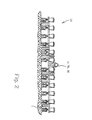
Fig. 2 is an end view of the seeding machine having the monitoring and control unit as shown inFig. 1 ; -
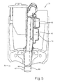
Fig. 3 is a perspective view of a row unit having a metering and placement system that can be used in an embodiment of the seeding machine ofFigs. 1 and2 ; -
Fig. 4 is a perspective partially exploded view of the metering system shown inFig. 3 ; -
Fig. 5 is a partially sectioned view of the metering system ofFigs. 3 and4 ; -
Fig. 6 is plan view showing an example of seed spacing in twin-row; -
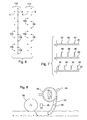
Fig. 7 is a graph showing exemplary signals used in control of seed placement; -
Fig. 8 is a schematic side view of the row unit showing alternative sensor locations; -
Fig. 9 is block diagram illustrating an alternative arrangement of the meter drive and control system components; and -
Fig. 10 is a block diagram illustrating another alternative arrangement of the meter drive and control system components. - Referring now to the drawings, and more particularly to
Fig. 1 , there is shown anagricultural system 10 including atractor 12 andseeding machine 14.Seeding machine 14 is in the form of arow crop planter 14, but could be a grain drill. Tractor 12 provides the motive power forplanter 14 and the mechanisms therein. A seed spacing monitoring/control system 16 is incorporated and used by the operator oftractor 12 to monitor the placing of seeds, fromplanter 14. - Now, additionally referring to
Figs. 2-5 , there is shown details ofplanter 14 that includestool bar 20,seed supply 22,row units 24 each including ametering device 26 having aseed disk 28 withholes 30 therein.Metering devices 26 are either directly or indirectly connected totool bar 20 that is in turn coupled withtractor 12. Seed is supplied tometering devices 26 by way ofseed supply 22 and the seed is pooled over a portion ofseed disk 28.Seed disk 28 is fluidly coupled to an airflow generator that supplies airflow to acavity 46 and/or acavity 48. The airflow generator may produce a positive or negative pressure depending on the configuration ofplanter 14. For ease of explanation the airflow will be understood to be a vacuum system. Airflow caused by the vacuum system is supplied tocavities 46 and/or 48 and thereby to one side ofseed disk 28 causing air to flow throughholes 30. The air flowing throughholes 30 attracts seeds thereto asseed disk 28 is rotated through the pooled seeds inmetering device 26. Seeds are connected withholes 30 and rotate from the pooled seeds to a point of discharge, as illustrated as a dashed line inFig. 5 , frommetering device 26 so that it may travel, by way of aseed placement system 50, to the prepared furrow in the soil. As described, theseed disk 28 is the metering member. Other meters having different types of metering members can also be used with the present invention such seed plates, metering belts or finger plates. -
Row unit 24 additionally carries a double disc furrow opener 52 (Fig. 3 ) for forming the seed furrow in the soil. Anoptional coulter wheel 54, particularly for use in no-till situations, may be placed ahead of double disc furrow opener 52. A pair ofgauge wheels 56 are respectively associated with the pair of discs of double disc furrow opener 52. More particularly, eachgauge wheel 56 is positioned generally in line with and immediately adjacent to the outside of each respective disc of double disc furrow opener 52. Eachgauge wheel 56 may be vertically adjusted to adjust the depth of the furrow which is cut into the soil using double disc furrow opener 52. - A pair of closing
wheels 58 is also part ofrow unit 24. Closingwheels 58 are positioned generally in line with double disc furrow opener 52. Closingwheels 58 are preferably biased in a downward direction and have a peripheral edge with a shape which may vary, depending upon the application.Seed placement system 50 is shown in the form of a gravity drop seed tube 42 (Fig. 3 ), but could be configured differently, such as a power drop seed placement system with a powered wheel, etc. -
Seed metering system 26 receives seed from a main seed supply, such as seed from a distant main seed hopper which is supplied via air or the like, or a seed hopper carried bytool bar 20 or a frame ofrow unit 24. Within the housing ofmetering system 26 there is a seed pool area.Seed disk 28 has a plurality ofholes 30 having seed cells on the seed side ofdisk 28 intermittently spaced about the periphery thereof. The vacuum airflow promotes entry of the seeds into the seed cells and maintains the seeds in place within the seed cells. Seeds are transported from the seed cells to seedplacement system 50. Of course,seed meter 26 may be configured with a positive pressure to assist in seed movement rather than a vacuum pressure. - Row crops require accurate population levels or seeding rates to achieve maximum yields. Some crops, such as corn and cotton, yield best with even, precise plant spacing or plant-to-plant distances within a given row. In a twin-row application, it is not only desired to precisely space plants within one row, but also to precisely space the plants in both rows of the twin-rows such that seeds in one row are evenly spaced relative to seeds in the adjacent twin row. For example, if the desired seed population results in 12 inch (30.5cm) spacing within the rows, when a seed is planted in one row, it is desired to plant a seed in the adjacent twin row 6 inches (15.25cm) later. An example of synchronized seed spacing between rows is shown in the twin row application shown in
Fig. 6 . There,twin rows seeds seeds 108 in row B alternate with theseeds 106 in row A. The present invention evaluates the spacing of the seeds between rows by utilizing sensor input from detecting a parameter related to seed placement and provides means to adjust the seed spacing during planting operation to achieve consistent control of the plant-to-plant spacing of the seeds among multiple rows thereby optimizing yield over a field having the same seeding population but not having precise plant spacing. - The
row units 24 include a meter drive mechanism 64 for eachmetering device 26. The drive mechanism includes a transverse hex shaft 66 driven by a planter ground wheel 15. A flexible cable 68 drive is driven by the shaft 66 and in turn provides an input to a transmission 70. The transmission 70 is coupled to thedriveshaft 72 of themetering device 26. The transmission 70 includes a planetary gear system such as that shown inUS Patent 7,273,016 and incorporated herein by reference. The ring gear of the planetary system is driven by an electric motor 74 controlled by a controller 76. A master controller 78 generates a reference signal that is communicated to the motor controller 76. In addition, aseed sensor 80 located in theseed tube 42 generates a signal when a seed passes which is also communicated to the motor controller 76. Theseed sensor 80 is one of many different sensors that can be used in the present invention as described below. - With reference to
Fig. 7 , the top line A is thereference signal 84 generated by the master controller 78 which contains of a series ofpulses 82 spaced a predetermined time interval apart based on planting speed and desired seed spacing. The center line B is theoutput index signal 88 of theseed sensor 80 of a row unit. Thesignal 88 hasspikes 86 generated each time a seed passes the sensor. This index signal, in this example based on the passing seed, represents a parameter related to the placement of seed in the furrow beneath the row unit. A processing circuit of the motor controller 76 compares thereference signal 84 with theindex signal 88 generated by theseed sensor 80 and determines in the relationship there between. As shown, the seeds pass the sensor approximately at the same time as thepulses 82 of the reference signal are generated. The bottom signal line C is theindex signal 92 from an adjacent row unit of theplanter having spikes 90 generated from seeds passing thesensor 80 of that row unit. Theindex signal 92 is also compared to thereference signal 84 by the motor controller 76 of that row unit. As shown inFig. 7 , the seeds from second row unit are passing the sensor in approximately the middle of the time interval between thepulses 82 of thereference signal 84. As a result, the seeds in second row are evenly staggered relative to the seeds in first row. For a twin row seeding application, this is a desired relationship between the index signals of the two rows and the reference signal. If however, bothspikes pulses 82 of the reference signal, the seeds in the two rows would be placed adjacent to one another, not staggered. In that case, the motor controller of one or both row units would activate the motor 74 to alter the metering action of the seed meter by momentarily changing the speed of thedrive shaft 72, thereby changing the timing of the seeds passing the associatedsensor 80. This example relationship between the signals assumes that the two row units are both located at the same fore and aft position relative to thetool bar 20. The desired signal relationship will need to consider the relative fore and aft locations of the row units. - The
reference signal 84 is communicated to each row unit of the seeding machine and each motor controller is selectively programmed to generate a desired relationship between the reference signal and index signal for that row. This results in producing a desired relationship between the seeds in two or more rows of the seedingmachine 14. It will be readily apparent that any type of drive mechanism may be used to drive the metering device that is capable of electronic control to alter the metering action by changing the speed of the metering member. The electro-mechanical drive 64 shown inFig. 3 is one example. A pure electric drive with motors for each meter is another possibility as are electrically controlled hydraulic motors. Another option is an electronically controlled clutch mechanism in the meter drive. Any transmission having two or more operating speeds can also be used to change the meter drive speed. - The
reference signal 84 is shown as a square wave analog signal. A sine wave or any other periodically varying signal. Alternatively, a periodic digital signal can be used as well. While an electronic signal is preferred, the reference signal may be transmitted by sound or light. - Various types and locations of sensors can be used as well as long as the sensor detects a parameter related to seed placement. With reference to
Fig. 8 other sensors and locations are shown schematically, including theseed sensor 80 on theseed tube 42. Aseed sensor 94 can be located adjacent theseed disk 28 to detect seed passing there. Likewise, aseed sensor 96 can be located to detect seed in the furrow. Sensor 98 can detect a feature in thedisk 28 orsensor 100 can detect a feature of the drive that indicates their rotational positions which then relates to seed placement. Sensing a feature of the metering member or meter drive requires a known relationship between the detected feature and the location of theholes 30 of the metering member. - The motor controllers 76 can be physically located on the row unit as shown in
Fig. 3 or can be part of the monitoring/control system 16 mounted on the planter frame or it could be located on the tractor. Individual controllers or processing circuits can be used to control each drive motor or a single controller or processing circuit can be used sequentially with each row unit. The master controller 78 generating thereference signal 84 is preferably part of the monitoring/control system 16. The motor controller or controllers and the processing circuit or circuits constitute a control means for receiving signals, determining the relationship between signals and controlling the meter drives to alter the metering action. The reference signal generation, when independent of the operation of any row unit may also be included in the control means or may be a separate component. The invention should not be limited to any particular device or devices to accomplish the determine the signal relationship or altering of the metering action. - An alternative system is shown schematically in
Fig. 9 . A first row unit has ameter drive motor 174, amotor controller 176 and asensor 180. A second row unit likewise hasmeter drive motor 274,motor controller 276 andsensor 280. Additional row units three and beyond, are similarly constructed. The index signal from thesensor 180 of the first row unit is communicated to acontroller 276 of a second row units controlling themotor 274. The associatedsensor 280 provides an index signal for second row unit to thecontroller 276. The index signal fromsensor 180 is also communicated to additional row units. In this embodiment, the reference signal, instead of being generated by a master controller, is generated by the sensor of the first row unit. The motor controllers of the other row units are programmed to provide a desired relationship between the index signals of their respective row units and the reference signal produced by the first row unit. - A third arrangement is shown in
Fig. 10 with two sets of twin rows shown,twin row 200 havingrow units twin rows 300 havingrow units Row units drive motor 174,motor controller 176, and associatedsensor 180.Row units drive motor 274,motor controller 276, and associatedsensor 280. The index signal from eachsensor 180 is communicated tocontroller 276 associated twin row as the reference signal.Controllers 276 are selectively programmed to produce the desired relationship between the reference signal fromsensors 180 and the index signal fromsensors 280 to produce the desired relationship between the seeds in thetwin rows twin rows - A display 36 and controls 40 of monitoring system 16 may be located in an operating position to provide information to the operator. In one form of the invention, the processing circuit is programmed to make the necessary alterations to the metering action to achieve the desired relationship in seed placement. In another implementation of the invention, the relationship between the reference signal and the index signal for a given row unit is displayed to the operator. A manual input device, such as a knob, dial, touch screen feature, etc. on the display can be used by the operator to momentarily adjust the speed of the metering device, thereby changing the relationship between the signals.
- The processing circuit additionally receives a speed signal that relates to a speed of
tractor 12 and/orplanter 14 upon the ground from aspeed sensor 18.Speed sensor 18 may be ontractor 12 orplanter 14 and the signal is representative of the speed ofplanter 14 across the ground. The speed signal may be conveyed to the processing circuit by way of a communication of the signal fromtractor 12, or the speed can be determined by the placement ofspeed sensor 18 onplanter 14 withspeed sensor 18 being associated with a ground contacting wheel, a global positioning system, a sonar system directed at the ground or a radar system directed at the ground, or the like. The speed signal can be used by the control system 16 to establish the meter drive speeds. In addition, the ground speed is used by the master controller 78 to determine the frequency of thepulses 82 in thereference signal 84. -
Seed sensor 80 when in theseed tube 42 may be in the form of an optical sensor with a light source located on one side of seed tube and a light sensor on an opposite side ofseed tube 42. Other types of seed sensors can be used on the seed tube or on the metering device or seed furrow as desired. Various non-contact sensors can be used to detect a feature of the metering member or drive such as optical sensors or electromagnetic sensors, etc. - Alternatively, a clutch in the seed meter drive mechanism, such as shown in
US Patent Application 12/062158, filed April 3, 2008 - Having described the preferred embodiment, it will become apparent that various modifications can be made without departing from the scope of the invention as defined in the accompanying claims.
Claims (15)
- A seeding machine (14) comprising: means for generating a reference signal (84); multiple row units (24, 201, 202, 301, 302), at least one row unit (24, 201, 202, 301, 302) having: a seed metering device (26) providing a metering action to a plurality of seeds; a drive (64) for the seed metering device (26) and a sensor (80, 94, 96, 98, 100, 180) adapted to sense a seed meter parameter, characterized in that the seed meter parameter relates to seed location in a furrow beneath the row unit (24, 201, 202, 301, 302) and the sensor generating an index signal (88); and control means for receiving the index signal (88) from the sensor (80, 94, 96, 98, 100, 180) and for receiving the reference signal (84), the control means determining a relationship between the index signal (88) and the reference signal (84) and the control means being operably coupled to the drive (64) for altering the metering action of the seed metering device (26) to establish a desired relationship between the index signal (88) and the reference signal (84).
- The seeding machine (14) as defined by claim 1 further comprising means for displaying to an operator the current relationship between the index signal (88) and the reference signal (84) and manual means for inputting to the control means a change to the metering action of the seed metering device (26) of the at least one row unit (24, 201, 202, 301, 302) to establish a desired relationship between the index signal (88) and the reference signal (84).
- The seeding machine (14) as defined in claim 1 or 2 where the sensor (80, 94, 96, 98, 100, 180) is a seed sensor operable to sense the passing of seed and being located to sense seed passing on the seed metering device (26).
- The seeding machine (14) as defined in claim 1 or 2 further comprising a seed placement device (50) receiving the seed from the seed metering device (26) and delivering seed to a furrow formed in soil beneath the row unit (24, 201, 202, 301, 302) and wherein the sensor (80, 94, 96, 98, 100, 180) is a seed sensor operable to sense the passing of seed and being located to sense seed passing through the seed placement device (50).
- The seeding machine (14) as defined in claim 1 or 2 wherein the sensor (80, 94, 96, 98, 100, 180) is a seed sensor operable to sense the passing of seed and being located to sense seed passing in the furrow beneath the row unit (24, 201, 202, 301, 302).
- The seeding machine (14) as defined in one of the claims 1 to 5 wherein the relationship between the index signal (88) and the reference signal (84) is based on the time between the reference signal (84) and the index signal (88).
- The seeding machine (14) as defined in one of the claims 1 to 6 wherein the sensor (80, 94, 96, 98, 100, 180) senses a feature of one of the seed metering device (26) and the drive (64) for the seed metering device (26), wherein the drive (64) is a variable speed drive variable independently of the drive of other row units (24, 201, 202, 301, 302).
- The seeding machine (14) as defined in one of the claims 1 to 7 wherein the index signal (88) of a first row unit (24, 201, 202, 301, 302) is received as the reference signal (84) by the control means of one or more other row units (24, 201, 202, 301, 302).
- The seeding machine (14) as defined in one of the claims 1 to 8 wherein the multiple row units (24, 201, 202, 301, 302) are arranged in pairs with the sensor (80, 94, 96, 98, 100, 180) of a first row unit (24, 201, 202, 301, 302) of the pair generating the reference signal (84) received by the control means of the second row unit (24, 201, 202, 301, 302) of the pair and wherein the sensor (80, 94, 96, 98, 100, 180) senses the passage of seed and produces a signal in response thereto or the sensor (80, 94, 96, 98, 100, 180) senses a feature of one of the seed metering device (26) and the drive (50) and produces a signal in response thereto.
- A method for operating a seeding machine (14), including coordinating the placement of seed planted by multiple row units (24, 201, 202, 301, 302) of a planter each having a seed meter (26), the method comprising the steps of: generating a reference signal (84); operating the multiple row units (24, 201, 202, 301, 302); sensing a parameter related to seed placement for one or more row units (24, 201, 202, 301, 302) and generating an index signal (88) for each of the one or more row units (24, 201, 202, 301, 302) in response thereto; determining a relationship between the reference signal (84) and the index signal (88) for each of the one or more row units (24, 201, 202, 301, 302); and altering the metering action of the seed meter (26) of one or more of the row units (24, 201, 202, 301, 302) to establish a desired relationship between the index signal (88) for each of the one or more row units (24, 201, 202, 301, 302) and the reference signal (84).
- The method as defined by claim 10 further comprising the step of displaying to an operator the relationship between the reference signal (84) and the index signal (88) of one of the row units (24, 201, 202, 301, 302).
- The method as defined by claim 10 or 11 wherein the sensing step senses the passing of seed, wherein the sensing step senses seed in the seed meter (26) of the row unit (24, 201, 202, 301, 302) or in a seed furrow in the soil or between the seed meter (26) and a seed furrow in the soil.
- The method as defined by one of the claims 10 to 12 wherein the sensing step senses a feature of one of a seed meter (26) and a seed meter drive (50).
- The method as defined by one of the claims 10 to 13 wherein the step of altering the metering action of the seed meter (26) of one or more row units (24, 201, 202, 301, 302) changes the speed of a seed meter drive (50).
- The method as defined one of the claims 10 to 14 wherein the reference signal (84) is the index signal of one row unit (24, 201, 202, 301, 302).
Applications Claiming Priority (1)
| Application Number | Priority Date | Filing Date | Title |
|---|---|---|---|
| US12/401,682 US7726251B1 (en) | 2009-03-11 | 2009-03-11 | Agricultural seeding apparatus and method for seed placement synchronization between multiple rows |
Publications (2)
| Publication Number | Publication Date |
|---|---|
| EP2227932A1 true EP2227932A1 (en) | 2010-09-15 |
| EP2227932B1 EP2227932B1 (en) | 2019-03-27 |
Family
ID=42200086
Family Applications (1)
| Application Number | Title | Priority Date | Filing Date |
|---|---|---|---|
| EP10155385.7A Active EP2227932B1 (en) | 2009-03-11 | 2010-03-03 | Agricultural seeding machine |
Country Status (6)
| Country | Link |
|---|---|
| US (1) | US7726251B1 (en) |
| EP (1) | EP2227932B1 (en) |
| AR (1) | AR076100A1 (en) |
| BR (1) | BRPI1000564A2 (en) |
| MX (1) | MX2010002751A (en) |
| RU (1) | RU2010107089A (en) |
Cited By (8)
| Publication number | Priority date | Publication date | Assignee | Title |
|---|---|---|---|---|
| EP2636292A1 (en) | 2012-03-09 | 2013-09-11 | Deere & Company | Assembly and method for the precision sowing of seed grains |
| EP2870848A1 (en) * | 2013-11-12 | 2015-05-13 | Dickey-John Corporation | Synchronization of a twin row planting system |
| EP2701483A4 (en) * | 2011-04-27 | 2015-05-20 | Kinze Mfg Inc | Agricultural devices, systems, and methods for determining soil and seed characteristics and analyzing the same |
| WO2016165697A1 (en) * | 2015-04-15 | 2016-10-20 | Lemken Gmbh & Co Kg | Agricultural seed drill |
| WO2017052483A1 (en) * | 2015-09-22 | 2017-03-30 | Özdöken Tarim Makinalari Sanayi Ve Ticaret Anonim Sirketi | Twin row seed distributor system |
| US10219430B2 (en) | 2011-04-27 | 2019-03-05 | Kinze Manufacturing, Inc. | Agricultural devices, systems, and methods for determining soil and seed characteristics and analyzing the same |
| EP3569045A1 (en) | 2018-05-15 | 2019-11-20 | Deere & Company | Method and machine for plant cultivation on a field |
| US11083127B2 (en) | 2018-05-09 | 2021-08-10 | Deere & Company | Seeding machine to provide transverse tramlines |
Families Citing this family (63)
| Publication number | Priority date | Publication date | Assignee | Title |
|---|---|---|---|---|
| US20090118910A1 (en) * | 2007-11-02 | 2009-05-07 | Gary W. Clem, Inc. | Method of operating a planter for planting seeds in a field for experimental purposes |
| US8671856B2 (en) | 2009-02-02 | 2014-03-18 | Deere & Company | Planting unit for a seeding machine having blocking member to control hand-off of seed from a seed meter to a seed delivery system |
| US8850995B2 (en) | 2009-02-02 | 2014-10-07 | Deere & Company | Seeding machine with seed delivery system |
| CA2704416C (en) * | 2010-05-14 | 2013-08-13 | Bourgault Industries Ltd. | Depth adjustment of trailing arm furrow openers |
| US10285325B2 (en) | 2010-07-02 | 2019-05-14 | Deere & Company | Seeding apparatus and method of determining a seed spacing variability value |
| US8365679B2 (en) | 2010-08-20 | 2013-02-05 | Deere & Company | Seed spacing monitoring system for use in an agricultural seeder |
| US8418636B2 (en) | 2010-08-20 | 2013-04-16 | Deere & Company | In-ground seed spacing monitoring system for use in an agricultural seeder |
| US8631749B2 (en) * | 2011-01-04 | 2014-01-21 | Precision Planting Llc | Seed tube egress-mounted seed sensor |
| RU2562211C2 (en) | 2011-04-27 | 2015-09-10 | Кинз Мэньюфэкчеринг, Инк. | Remote control of inline unit of device of agricultural use |
| US10327374B2 (en) * | 2011-04-27 | 2019-06-25 | Kinze Manufacturing, Inc. | Remote adjustment of a row unit of an agricultural device |
| EP2701482B1 (en) | 2011-04-27 | 2018-06-06 | Kinze Manufacturing, Inc. | Down and/or up force adjustment system |
| WO2013112929A2 (en) | 2012-01-25 | 2013-08-01 | Precision Planting Llc | Agricultural toolbar apparatus, systems, and methods |
| ITBO20120139A1 (en) * | 2012-03-16 | 2013-09-17 | Delta Progetti S R L | GROUP OF SEEDING AND METHOD FOR IMPLEMENTING A SEEDING GROUP |
| RU2600182C2 (en) | 2012-06-28 | 2016-10-20 | Кинз Мэньюфэкчеринг, Инк. | Bulk handling system for seed sowing machines and machines for products input |
| LT2876993T (en) * | 2012-07-25 | 2017-11-10 | Precision Planting Llc | System and method for multi-row agricultural implement control and monitoring |
| US9310233B2 (en) * | 2012-08-16 | 2016-04-12 | CHS, Inc. | Flow rate monitoring for agrochemical applications |
| BR102012021028A2 (en) * | 2012-08-22 | 2014-12-09 | Janice Silvestri | FLEXIBLE ELASTIC TURNTABLE TRANSMISSION SHAFT APPLIED ON GRAIN, SEED, FERTILIZER AND INDUSTRIAL EQUIPMENT PLANTER |
| LT3375273T (en) | 2013-03-14 | 2019-12-27 | Precision Planting Llc | Systems for agricultural implement trench depth control and soil monitoring |
| US9651536B1 (en) | 2013-04-15 | 2017-05-16 | Veris Technologies, Inc. | Method and system for measuring multiple soil properties |
| BR112015027510B1 (en) | 2013-04-30 | 2022-06-28 | Precision Planting Llc | METHOD FOR MONITORING A SEED APPLICATION RATE OF A SEED PLANTER PLANTING SEEDS FROM A SEED DOSER, AND METHOD FOR MONITORING THE PERFORMANCE OF A SEED PLANTER PLANTING SEEDS USING A DOSING SYSTEM INCLUDING A SEED DOSER |
| BR112015031840B1 (en) * | 2013-06-21 | 2020-11-03 | Precision Planting Llc | agricultural seed drill |
| CN103650679B (en) * | 2013-11-27 | 2016-01-06 | 山东农业大学 | A kind of corn subsoiling deep fertilizer spraying seed manure planter |
| US10785905B2 (en) | 2014-05-08 | 2020-09-29 | Precision Planting Llc | Liquid application apparatus comprising a seed firmer |
| EA031045B1 (en) * | 2014-05-22 | 2018-11-30 | Владимир Ильич Сесякин | Method of direct seeding of agricultural crops and device for implementation thereof |
| RU2671094C1 (en) | 2014-10-17 | 2018-10-29 | Грейт Плейнз Мануфэкчеринг, Инкорпорейтед | System and method of delivering seeds and process material |
| CA2904756C (en) | 2014-11-04 | 2020-01-07 | Cnh Industrial Canada, Ltd. | Independently controlled meter rollers and air conveyance components system and method |
| CA2904778C (en) | 2014-11-04 | 2020-03-10 | Cnh Industrial Canada, Ltd. | System and method for independent calibration of meter rollers |
| US10561059B2 (en) | 2015-06-15 | 2020-02-18 | Precision Planting Llc | Systems, methods, and apparatus for agricultural liquid application |
| US9930826B2 (en) | 2015-06-15 | 2018-04-03 | Robert Craig McCloskey | Data acquisition system for a seed planter |
| RU2711943C2 (en) * | 2015-07-14 | 2020-01-23 | ПРЕСИЖН ПЛЭНТИНГ ЭлЭлСи | Device, systems and methods for seeds delivery |
| DE102015114147A1 (en) * | 2015-08-26 | 2017-03-02 | Amazonen-Werke H. Dreyer Gmbh & Co. Kg | Dosing device for granular material with grain counter |
| US10709058B2 (en) | 2015-08-31 | 2020-07-14 | Cnh Industrial Canada, Ltd. | Flow control system for an agricultural metering system |
| US9854732B2 (en) | 2015-08-31 | 2018-01-02 | Cnh Industrial Canada, Ltd. | Metering system for an agricultural vehicle |
| DE102015217496A1 (en) * | 2015-09-14 | 2017-03-16 | Deere & Company | Method for spreading seed particles or plants on a field and a corresponding machine |
| EP3410836A1 (en) | 2016-02-05 | 2018-12-12 | Actuant Corporation | Seed metering device drive system and method |
| US10159177B2 (en) * | 2016-08-11 | 2018-12-25 | Cnh Industrial Canada, Ltd. | Flow control system for an agricultural product application system |
| WO2018085422A1 (en) * | 2016-11-01 | 2018-05-11 | Kinze Manufacturing, Inc. | Control units, nodes, system, and method for transmitting and communicating data |
| BR112019012697B1 (en) | 2016-12-19 | 2023-05-16 | Climate Llc | COMPUTER SYSTEM AND COMPUTER-IMPLEMENTED METHOD FOR MONITORING SOIL AND SEEDS |
| US10455758B2 (en) | 2017-05-11 | 2019-10-29 | Cnh Industrial America Llc | Seed level detection in a seed meter |
| US10481617B2 (en) | 2017-08-10 | 2019-11-19 | Cnh Industrial Canada, Ltd. | Metering system for an agricultural system |
| EP4230016A1 (en) | 2017-10-02 | 2023-08-23 | Precision Planting LLC | Systems and apparatuses for soil and seed monitoring |
| US10820488B2 (en) | 2018-03-16 | 2020-11-03 | Cnh Industrial America Llc | Systems and methods for monitoring the operation of a seed meter |
| US11412652B2 (en) * | 2018-05-21 | 2022-08-16 | 360 Yield Center, Llc | Crop input application systems, methods, and apparatuses |
| US10750662B2 (en) | 2018-06-01 | 2020-08-25 | Deere & Company | Seed sensor |
| US11051445B2 (en) | 2018-06-27 | 2021-07-06 | Deere & Company | Seeding system |
| US11064649B2 (en) | 2018-06-27 | 2021-07-20 | Deere & Company | Seeding system |
| US11058047B2 (en) | 2018-06-27 | 2021-07-13 | Deere & Company | Seeding system |
| US11191204B2 (en) | 2019-02-18 | 2021-12-07 | Cnh Industrial Canada, Ltd. | System and method for monitoring soil conditions within a field |
| US11197412B2 (en) | 2019-08-08 | 2021-12-14 | Deere & Company | Automatic rank selection |
| US11765991B2 (en) | 2019-11-14 | 2023-09-26 | Cnh Industrial Canada, Ltd. | Particulate material metering system for an agricultural implement |
| CA3097708A1 (en) | 2019-11-14 | 2021-05-14 | Cnh Industrial Canada, Ltd. | Particulate material metering system for an agricultural implement |
| US11589500B2 (en) | 2019-12-24 | 2023-02-28 | Cnh Industrial America Llc | Particle delivery system of an agricultural row unit |
| US11596095B2 (en) | 2019-12-24 | 2023-03-07 | Cnh Industrial America Llc | Particle delivery system of an agricultural row unit |
| US11564344B2 (en) | 2019-12-24 | 2023-01-31 | Cnh Industrial America Llc | Particle delivery system of an agricultural row unit |
| US11553639B2 (en) | 2019-12-24 | 2023-01-17 | Cnh Industrial America Llc | Particle delivery system of an agricultural row unit |
| US11582899B2 (en) | 2019-12-24 | 2023-02-21 | Cnh Industrial America Llc | Particle delivery system of an agricultural row unit |
| US11564346B2 (en) | 2019-12-24 | 2023-01-31 | Cnh Industrial America Llc | Particle delivery system of an agricultural row unit |
| US11490558B2 (en) | 2019-12-24 | 2022-11-08 | Cnh Industrial America Llc | Particle delivery system of an agricultural row unit |
| US11553638B2 (en) | 2019-12-24 | 2023-01-17 | Cnh Industrial America Llc | Particle delivery system of an agricultural row unit |
| US11483963B2 (en) | 2019-12-24 | 2022-11-01 | Cnh Industrial America Llc | Particle delivery system of an agricultural row unit |
| US11523555B2 (en) | 2019-12-24 | 2022-12-13 | Cnh Industrial America Llc | Particle delivery system of an agricultural row unit |
| US11523556B2 (en) | 2019-12-24 | 2022-12-13 | Cnh Industrial America Llc | Particle delivery system of an agricultural row unit |
| US11516958B2 (en) | 2019-12-24 | 2022-12-06 | Cnh Industrial America Llc | Particle delivery system of an agricultural row unit |
Citations (4)
| Publication number | Priority date | Publication date | Assignee | Title |
|---|---|---|---|---|
| WO1986005352A1 (en) * | 1985-03-22 | 1986-09-25 | Paul Karl Heinz | Process and apparatus for sowing and/or planting maize, sugar beets, beans, grain, or similar |
| EP0282813A1 (en) | 1987-03-13 | 1988-09-21 | Amazonen-Werke H. Dreyer GmbH & Co. KG | Single grain seeder |
| US6070538A (en) * | 1996-11-22 | 2000-06-06 | Case Corporation | Modular agricultural implement control system |
| EP1415523A1 (en) | 2002-11-02 | 2004-05-06 | Kverneland ASA | Sowing machine |
Family Cites Families (31)
| Publication number | Priority date | Publication date | Assignee | Title |
|---|---|---|---|---|
| US5260875A (en) * | 1991-08-20 | 1993-11-09 | Micro-Trak System, Inc. | Networked agricultural monitoring and control system |
| US5323721A (en) * | 1992-03-20 | 1994-06-28 | Micro-Trak Systems, Inc. | Planter monitor system |
| US5585626A (en) * | 1992-07-28 | 1996-12-17 | Patchen, Inc. | Apparatus and method for determining a distance to an object in a field for the controlled release of chemicals on plants, weeds, trees or soil and/or guidance of farm vehicles |
| US5407134A (en) * | 1992-12-07 | 1995-04-18 | Fmc Corporation | Liquid distribution system |
| US5685245A (en) * | 1993-06-08 | 1997-11-11 | Bassett; James H. | Planter unit |
| US5709271A (en) * | 1993-06-08 | 1998-01-20 | Dawn Equipment Company | Agricultural planter |
| US5621666A (en) * | 1995-04-20 | 1997-04-15 | Dynavisions, Inc. | Planter monitor |
| US5740746A (en) * | 1995-08-11 | 1998-04-21 | Case Corporation | Seed material dispensing system for an agricultural planter |
| US6070539A (en) * | 1997-03-21 | 2000-06-06 | Case Corporation | Variable rate agricultural product application implement with multiple inputs and feedback |
| US5915313A (en) * | 1997-03-21 | 1999-06-29 | Case Corporation | Multiple-type seed dispensing system |
| US5924371A (en) * | 1997-09-23 | 1999-07-20 | Case Corporation | Global controller and distributed local controller(s) for an agricultural implement |
| US6024035A (en) * | 1997-09-23 | 2000-02-15 | Case Corporation | Seed planting rate maintenance control with rate display |
| US6079340A (en) * | 1997-09-23 | 2000-06-27 | Case Corporation | Apparatus for customizing the rate at which farming material is applied to an agricultural field |
| US6009354A (en) * | 1997-09-23 | 1999-12-28 | Case Corporation | Enhanced implement control |
| US6091997A (en) * | 1997-09-23 | 2000-07-18 | Case Corporation | Enhanced statistical/status display |
| US5956255A (en) * | 1997-09-23 | 1999-09-21 | Case Corporation | Seed planter performance monitor |
| US6039141A (en) * | 1998-02-23 | 2000-03-21 | Case Corporation | Moving operator and display unit |
| US6003455A (en) * | 1998-03-05 | 1999-12-21 | Case Corporation | Regulator control |
| US6145455A (en) * | 1999-03-17 | 2000-11-14 | Case Corporation | Agricultural material metering system |
| US6626120B2 (en) * | 2000-12-06 | 2003-09-30 | Jim Bogner | Precision air planter for plot planting |
| US6671698B2 (en) * | 2002-03-20 | 2003-12-30 | Deere & Company | Method and system for automated tracing of an agricultural product |
| US6863006B2 (en) * | 2003-04-08 | 2005-03-08 | Cnh America Llc | Drive mechanism for agricultural planters |
| US7370589B2 (en) * | 2003-04-24 | 2008-05-13 | University Of Tennessee Research Foundation | Systems and methods for fluid dispensing |
| US20050150160A1 (en) * | 2003-10-28 | 2005-07-14 | Norgaard Daniel G. | Method for selecting crop varieties |
| US7270147B2 (en) * | 2003-11-07 | 2007-09-18 | Cnh Canada, Ltd. | Adjustable variable flow fertilizer valve |
| US7140310B2 (en) * | 2003-11-18 | 2006-11-28 | Cnh Canada, Ltd. | System and method for distributing multiple materials from an agricultural vehicle |
| US7273016B2 (en) | 2004-05-20 | 2007-09-25 | Deere & Company | Variable speed drive for agricultural seeding machines |
| US7478603B2 (en) * | 2006-05-18 | 2009-01-20 | Deere & Company | Seed meter monitoring system |
| US7377221B1 (en) | 2006-11-10 | 2008-05-27 | Monosem, Inc. | Twin row planter with adjustable seed metering |
| US7717048B2 (en) * | 2007-10-09 | 2010-05-18 | Deere & Company | Agricultural seeding system |
| US7640876B2 (en) * | 2007-12-03 | 2010-01-05 | Cnh Canada, Ltd. | Bin level sensor for use with a product dispensing agricultural implement |
-
2009
- 2009-03-11 US US12/401,682 patent/US7726251B1/en active Active
-
2010
- 2010-02-25 RU RU2010107089/13A patent/RU2010107089A/en not_active Application Discontinuation
- 2010-03-03 EP EP10155385.7A patent/EP2227932B1/en active Active
- 2010-03-09 AR ARP100100702A patent/AR076100A1/en active IP Right Grant
- 2010-03-09 BR BRPI1000564-1A patent/BRPI1000564A2/en not_active Application Discontinuation
- 2010-03-11 MX MX2010002751A patent/MX2010002751A/en active IP Right Grant
Patent Citations (4)
| Publication number | Priority date | Publication date | Assignee | Title |
|---|---|---|---|---|
| WO1986005352A1 (en) * | 1985-03-22 | 1986-09-25 | Paul Karl Heinz | Process and apparatus for sowing and/or planting maize, sugar beets, beans, grain, or similar |
| EP0282813A1 (en) | 1987-03-13 | 1988-09-21 | Amazonen-Werke H. Dreyer GmbH & Co. KG | Single grain seeder |
| US6070538A (en) * | 1996-11-22 | 2000-06-06 | Case Corporation | Modular agricultural implement control system |
| EP1415523A1 (en) | 2002-11-02 | 2004-05-06 | Kverneland ASA | Sowing machine |
Cited By (15)
| Publication number | Priority date | Publication date | Assignee | Title |
|---|---|---|---|---|
| US10219430B2 (en) | 2011-04-27 | 2019-03-05 | Kinze Manufacturing, Inc. | Agricultural devices, systems, and methods for determining soil and seed characteristics and analyzing the same |
| EP2701483A4 (en) * | 2011-04-27 | 2015-05-20 | Kinze Mfg Inc | Agricultural devices, systems, and methods for determining soil and seed characteristics and analyzing the same |
| US11185010B2 (en) | 2011-04-27 | 2021-11-30 | Kinze Manufacturing, Inc. | Agricultural devices, systems, and methods for determining soil and seed characteristics and analyzing the same |
| DE102012203761A1 (en) | 2012-03-09 | 2013-09-12 | Deere & Company | Arrangement and method for precision sowing of seeds |
| AU2013201245B2 (en) * | 2012-03-09 | 2015-02-19 | Deere & Company | Assembly and method for the precision drilling of seed grains |
| EP2636292A1 (en) | 2012-03-09 | 2013-09-11 | Deere & Company | Assembly and method for the precision sowing of seed grains |
| US9179595B2 (en) | 2012-03-09 | 2015-11-10 | Deere & Company | Assembly and method for the precision drilling of seed grains |
| EP2870848A1 (en) * | 2013-11-12 | 2015-05-13 | Dickey-John Corporation | Synchronization of a twin row planting system |
| US9320192B2 (en) | 2013-11-12 | 2016-04-26 | Dickey-John Corporation | Synchronization of a twin row planting system |
| WO2016165697A1 (en) * | 2015-04-15 | 2016-10-20 | Lemken Gmbh & Co Kg | Agricultural seed drill |
| US10512208B2 (en) | 2015-04-15 | 2019-12-24 | Lemken Gmbh & Co Kg | Agricultural seed drill |
| WO2017052483A1 (en) * | 2015-09-22 | 2017-03-30 | Özdöken Tarim Makinalari Sanayi Ve Ticaret Anonim Sirketi | Twin row seed distributor system |
| US11083127B2 (en) | 2018-05-09 | 2021-08-10 | Deere & Company | Seeding machine to provide transverse tramlines |
| EP3569045A1 (en) | 2018-05-15 | 2019-11-20 | Deere & Company | Method and machine for plant cultivation on a field |
| US11134608B2 (en) | 2018-05-15 | 2021-10-05 | Deere & Company | Method and machine for plant cultivation on a field |
Also Published As
| Publication number | Publication date |
|---|---|
| MX2010002751A (en) | 2010-10-01 |
| AR076100A1 (en) | 2011-05-18 |
| BRPI1000564A2 (en) | 2011-03-22 |
| US7726251B1 (en) | 2010-06-01 |
| RU2010107089A (en) | 2011-08-27 |
| EP2227932B1 (en) | 2019-03-27 |
Similar Documents
| Publication | Publication Date | Title |
|---|---|---|
| EP2227932B1 (en) | Agricultural seeding machine | |
| EP2047735B1 (en) | Seeding machine and row unit of a seeding machine | |
| US10772256B2 (en) | Systems, methods, and apparatus for multi-row agricultural implement control and monitoring | |
| US9999175B2 (en) | Systems, methods and apparatus for multi-row agricultural implement control and monitoring | |
| EP2517545B1 (en) | Seeding machine | |
| US10709059B2 (en) | Multiple seed-type planting system with seed delivery speed control | |
| EP2213153B1 (en) | Seed delivery apparatus and method for delivering seed | |
| US6863006B2 (en) | Drive mechanism for agricultural planters | |
| EP3725144A1 (en) | Systems and methods for spraying seeds dispensed from a high-speed planter | |
| EP2870848B1 (en) | Synchronization of a twin row planting system | |
| CA2451722C (en) | Seed metering system for use in a seeding machine | |
| EP2684436A1 (en) | Twin-row multiple variety planter and method of use | |
| WO2009046273A1 (en) | Ground driven seed metering system with a continuously variable transmission | |
| CN111448874A (en) | Seeding method and apparatus | |
| Soyoye | Development of the instrumentation unit of a motorized precision planter |
Legal Events
| Date | Code | Title | Description |
|---|---|---|---|
| PUAI | Public reference made under article 153(3) epc to a published international application that has entered the european phase |
Free format text: ORIGINAL CODE: 0009012 |
|
| AK | Designated contracting states |
Kind code of ref document: A1 Designated state(s): AT BE BG CH CY CZ DE DK EE ES FI FR GB GR HR HU IE IS IT LI LT LU LV MC MK MT NL NO PL PT RO SE SI SK SM TR |
|
| AX | Request for extension of the european patent |
Extension state: AL BA ME RS |
|
| 17P | Request for examination filed |
Effective date: 20110315 |
|
| STAA | Information on the status of an ep patent application or granted ep patent |
Free format text: STATUS: EXAMINATION IS IN PROGRESS |
|
| 17Q | First examination report despatched |
Effective date: 20180202 |
|
| GRAP | Despatch of communication of intention to grant a patent |
Free format text: ORIGINAL CODE: EPIDOSNIGR1 |
|
| STAA | Information on the status of an ep patent application or granted ep patent |
Free format text: STATUS: GRANT OF PATENT IS INTENDED |
|
| INTG | Intention to grant announced |
Effective date: 20181016 |
|
| GRAS | Grant fee paid |
Free format text: ORIGINAL CODE: EPIDOSNIGR3 |
|
| GRAA | (expected) grant |
Free format text: ORIGINAL CODE: 0009210 |
|
| STAA | Information on the status of an ep patent application or granted ep patent |
Free format text: STATUS: THE PATENT HAS BEEN GRANTED |
|
| AK | Designated contracting states |
Kind code of ref document: B1 Designated state(s): AT BE BG CH CY CZ DE DK EE ES FI FR GB GR HR HU IE IS IT LI LT LU LV MC MK MT NL NO PL PT RO SE SI SK SM TR |
|
| REG | Reference to a national code |
Ref country code: GB Ref legal event code: FG4D |
|
| REG | Reference to a national code |
Ref country code: CH Ref legal event code: EP |
|
| REG | Reference to a national code |
Ref country code: AT Ref legal event code: REF Ref document number: 1111873 Country of ref document: AT Kind code of ref document: T Effective date: 20190415 |
|
| REG | Reference to a national code |
Ref country code: IE Ref legal event code: FG4D |
|
| REG | Reference to a national code |
Ref country code: DE Ref legal event code: R096 Ref document number: 602010057778 Country of ref document: DE |
|
| PG25 | Lapsed in a contracting state [announced via postgrant information from national office to epo] |
Ref country code: NO Free format text: LAPSE BECAUSE OF FAILURE TO SUBMIT A TRANSLATION OF THE DESCRIPTION OR TO PAY THE FEE WITHIN THE PRESCRIBED TIME-LIMIT Effective date: 20190627 Ref country code: FI Free format text: LAPSE BECAUSE OF FAILURE TO SUBMIT A TRANSLATION OF THE DESCRIPTION OR TO PAY THE FEE WITHIN THE PRESCRIBED TIME-LIMIT Effective date: 20190327 Ref country code: LT Free format text: LAPSE BECAUSE OF FAILURE TO SUBMIT A TRANSLATION OF THE DESCRIPTION OR TO PAY THE FEE WITHIN THE PRESCRIBED TIME-LIMIT Effective date: 20190327 Ref country code: SE Free format text: LAPSE BECAUSE OF FAILURE TO SUBMIT A TRANSLATION OF THE DESCRIPTION OR TO PAY THE FEE WITHIN THE PRESCRIBED TIME-LIMIT Effective date: 20190327 |
|
| REG | Reference to a national code |
Ref country code: NL Ref legal event code: MP Effective date: 20190327 |
|
| PG25 | Lapsed in a contracting state [announced via postgrant information from national office to epo] |
Ref country code: LV Free format text: LAPSE BECAUSE OF FAILURE TO SUBMIT A TRANSLATION OF THE DESCRIPTION OR TO PAY THE FEE WITHIN THE PRESCRIBED TIME-LIMIT Effective date: 20190327 Ref country code: NL Free format text: LAPSE BECAUSE OF FAILURE TO SUBMIT A TRANSLATION OF THE DESCRIPTION OR TO PAY THE FEE WITHIN THE PRESCRIBED TIME-LIMIT Effective date: 20190327 Ref country code: BG Free format text: LAPSE BECAUSE OF FAILURE TO SUBMIT A TRANSLATION OF THE DESCRIPTION OR TO PAY THE FEE WITHIN THE PRESCRIBED TIME-LIMIT Effective date: 20190627 Ref country code: GR Free format text: LAPSE BECAUSE OF FAILURE TO SUBMIT A TRANSLATION OF THE DESCRIPTION OR TO PAY THE FEE WITHIN THE PRESCRIBED TIME-LIMIT Effective date: 20190628 Ref country code: HR Free format text: LAPSE BECAUSE OF FAILURE TO SUBMIT A TRANSLATION OF THE DESCRIPTION OR TO PAY THE FEE WITHIN THE PRESCRIBED TIME-LIMIT Effective date: 20190327 |
|
| REG | Reference to a national code |
Ref country code: AT Ref legal event code: MK05 Ref document number: 1111873 Country of ref document: AT Kind code of ref document: T Effective date: 20190327 |
|
| PG25 | Lapsed in a contracting state [announced via postgrant information from national office to epo] |
Ref country code: ES Free format text: LAPSE BECAUSE OF FAILURE TO SUBMIT A TRANSLATION OF THE DESCRIPTION OR TO PAY THE FEE WITHIN THE PRESCRIBED TIME-LIMIT Effective date: 20190327 Ref country code: PT Free format text: LAPSE BECAUSE OF FAILURE TO SUBMIT A TRANSLATION OF THE DESCRIPTION OR TO PAY THE FEE WITHIN THE PRESCRIBED TIME-LIMIT Effective date: 20190727 Ref country code: SK Free format text: LAPSE BECAUSE OF FAILURE TO SUBMIT A TRANSLATION OF THE DESCRIPTION OR TO PAY THE FEE WITHIN THE PRESCRIBED TIME-LIMIT Effective date: 20190327 Ref country code: IT Free format text: LAPSE BECAUSE OF FAILURE TO SUBMIT A TRANSLATION OF THE DESCRIPTION OR TO PAY THE FEE WITHIN THE PRESCRIBED TIME-LIMIT Effective date: 20190327 Ref country code: RO Free format text: LAPSE BECAUSE OF FAILURE TO SUBMIT A TRANSLATION OF THE DESCRIPTION OR TO PAY THE FEE WITHIN THE PRESCRIBED TIME-LIMIT Effective date: 20190327 Ref country code: EE Free format text: LAPSE BECAUSE OF FAILURE TO SUBMIT A TRANSLATION OF THE DESCRIPTION OR TO PAY THE FEE WITHIN THE PRESCRIBED TIME-LIMIT Effective date: 20190327 Ref country code: CZ Free format text: LAPSE BECAUSE OF FAILURE TO SUBMIT A TRANSLATION OF THE DESCRIPTION OR TO PAY THE FEE WITHIN THE PRESCRIBED TIME-LIMIT Effective date: 20190327 |
|
| PG25 | Lapsed in a contracting state [announced via postgrant information from national office to epo] |
Ref country code: SM Free format text: LAPSE BECAUSE OF FAILURE TO SUBMIT A TRANSLATION OF THE DESCRIPTION OR TO PAY THE FEE WITHIN THE PRESCRIBED TIME-LIMIT Effective date: 20190327 Ref country code: PL Free format text: LAPSE BECAUSE OF FAILURE TO SUBMIT A TRANSLATION OF THE DESCRIPTION OR TO PAY THE FEE WITHIN THE PRESCRIBED TIME-LIMIT Effective date: 20190327 |
|
| PG25 | Lapsed in a contracting state [announced via postgrant information from national office to epo] |
Ref country code: IS Free format text: LAPSE BECAUSE OF FAILURE TO SUBMIT A TRANSLATION OF THE DESCRIPTION OR TO PAY THE FEE WITHIN THE PRESCRIBED TIME-LIMIT Effective date: 20190727 Ref country code: AT Free format text: LAPSE BECAUSE OF FAILURE TO SUBMIT A TRANSLATION OF THE DESCRIPTION OR TO PAY THE FEE WITHIN THE PRESCRIBED TIME-LIMIT Effective date: 20190327 |
|
| REG | Reference to a national code |
Ref country code: DE Ref legal event code: R097 Ref document number: 602010057778 Country of ref document: DE |
|
| PG25 | Lapsed in a contracting state [announced via postgrant information from national office to epo] |
Ref country code: DK Free format text: LAPSE BECAUSE OF FAILURE TO SUBMIT A TRANSLATION OF THE DESCRIPTION OR TO PAY THE FEE WITHIN THE PRESCRIBED TIME-LIMIT Effective date: 20190327 |
|
| PLBE | No opposition filed within time limit |
Free format text: ORIGINAL CODE: 0009261 |
|
| STAA | Information on the status of an ep patent application or granted ep patent |
Free format text: STATUS: NO OPPOSITION FILED WITHIN TIME LIMIT |
|
| PG25 | Lapsed in a contracting state [announced via postgrant information from national office to epo] |
Ref country code: SI Free format text: LAPSE BECAUSE OF FAILURE TO SUBMIT A TRANSLATION OF THE DESCRIPTION OR TO PAY THE FEE WITHIN THE PRESCRIBED TIME-LIMIT Effective date: 20190327 |
|
| 26N | No opposition filed |
Effective date: 20200103 |
|
| PG25 | Lapsed in a contracting state [announced via postgrant information from national office to epo] |
Ref country code: TR Free format text: LAPSE BECAUSE OF FAILURE TO SUBMIT A TRANSLATION OF THE DESCRIPTION OR TO PAY THE FEE WITHIN THE PRESCRIBED TIME-LIMIT Effective date: 20190327 |
|
| PG25 | Lapsed in a contracting state [announced via postgrant information from national office to epo] |
Ref country code: MC Free format text: LAPSE BECAUSE OF FAILURE TO SUBMIT A TRANSLATION OF THE DESCRIPTION OR TO PAY THE FEE WITHIN THE PRESCRIBED TIME-LIMIT Effective date: 20190327 |
|
| REG | Reference to a national code |
Ref country code: CH Ref legal event code: PL |
|
| REG | Reference to a national code |
Ref country code: BE Ref legal event code: MM Effective date: 20200331 |
|
| PG25 | Lapsed in a contracting state [announced via postgrant information from national office to epo] |
Ref country code: LU Free format text: LAPSE BECAUSE OF NON-PAYMENT OF DUE FEES Effective date: 20200303 |
|
| PG25 | Lapsed in a contracting state [announced via postgrant information from national office to epo] |
Ref country code: LI Free format text: LAPSE BECAUSE OF NON-PAYMENT OF DUE FEES Effective date: 20200331 Ref country code: CH Free format text: LAPSE BECAUSE OF NON-PAYMENT OF DUE FEES Effective date: 20200331 Ref country code: IE Free format text: LAPSE BECAUSE OF NON-PAYMENT OF DUE FEES Effective date: 20200303 |
|
| PG25 | Lapsed in a contracting state [announced via postgrant information from national office to epo] |
Ref country code: BE Free format text: LAPSE BECAUSE OF NON-PAYMENT OF DUE FEES Effective date: 20200331 |
|
| GBPC | Gb: european patent ceased through non-payment of renewal fee |
Effective date: 20200303 |
|
| PG25 | Lapsed in a contracting state [announced via postgrant information from national office to epo] |
Ref country code: GB Free format text: LAPSE BECAUSE OF NON-PAYMENT OF DUE FEES Effective date: 20200303 |
|
| PG25 | Lapsed in a contracting state [announced via postgrant information from national office to epo] |
Ref country code: MT Free format text: LAPSE BECAUSE OF FAILURE TO SUBMIT A TRANSLATION OF THE DESCRIPTION OR TO PAY THE FEE WITHIN THE PRESCRIBED TIME-LIMIT Effective date: 20190327 Ref country code: CY Free format text: LAPSE BECAUSE OF FAILURE TO SUBMIT A TRANSLATION OF THE DESCRIPTION OR TO PAY THE FEE WITHIN THE PRESCRIBED TIME-LIMIT Effective date: 20190327 |
|
| PG25 | Lapsed in a contracting state [announced via postgrant information from national office to epo] |
Ref country code: MK Free format text: LAPSE BECAUSE OF FAILURE TO SUBMIT A TRANSLATION OF THE DESCRIPTION OR TO PAY THE FEE WITHIN THE PRESCRIBED TIME-LIMIT Effective date: 20190327 |
|
| PGFP | Annual fee paid to national office [announced via postgrant information from national office to epo] |
Ref country code: FR Payment date: 20230328 Year of fee payment: 14 |
|
| PGFP | Annual fee paid to national office [announced via postgrant information from national office to epo] |
Ref country code: DE Payment date: 20230221 Year of fee payment: 14 |