EP3568905B1 - Bidirektionales ladegerät für elektrischen akkumulator - Google Patents
Bidirektionales ladegerät für elektrischen akkumulator Download PDFInfo
- Publication number
- EP3568905B1 EP3568905B1 EP18703046.5A EP18703046A EP3568905B1 EP 3568905 B1 EP3568905 B1 EP 3568905B1 EP 18703046 A EP18703046 A EP 18703046A EP 3568905 B1 EP3568905 B1 EP 3568905B1
- Authority
- EP
- European Patent Office
- Prior art keywords
- charger
- battery
- power factor
- factor correction
- midpoint
- Prior art date
- Legal status (The legal status is an assumption and is not a legal conclusion. Google has not performed a legal analysis and makes no representation as to the accuracy of the status listed.)
- Active
Links
Images

Classifications
-
- H—ELECTRICITY
- H02—GENERATION; CONVERSION OR DISTRIBUTION OF ELECTRIC POWER
- H02M—APPARATUS FOR CONVERSION BETWEEN AC AND AC, BETWEEN AC AND DC, OR BETWEEN DC AND DC, AND FOR USE WITH MAINS OR SIMILAR POWER SUPPLY SYSTEMS; CONVERSION OF DC OR AC INPUT POWER INTO SURGE OUTPUT POWER; CONTROL OR REGULATION THEREOF
- H02M1/00—Details of apparatus for conversion
- H02M1/42—Circuits or arrangements for compensating for or adjusting power factor in converters or inverters
- H02M1/4208—Arrangements for improving power factor of AC input
- H02M1/4216—Arrangements for improving power factor of AC input operating from a three-phase input voltage
-
- B—PERFORMING OPERATIONS; TRANSPORTING
- B60—VEHICLES IN GENERAL
- B60L—PROPULSION OF ELECTRICALLY-PROPELLED VEHICLES; SUPPLYING ELECTRIC POWER FOR AUXILIARY EQUIPMENT OF ELECTRICALLY-PROPELLED VEHICLES; ELECTRODYNAMIC BRAKE SYSTEMS FOR VEHICLES IN GENERAL; MAGNETIC SUSPENSION OR LEVITATION FOR VEHICLES; MONITORING OPERATING VARIABLES OF ELECTRICALLY-PROPELLED VEHICLES; ELECTRIC SAFETY DEVICES FOR ELECTRICALLY-PROPELLED VEHICLES
- B60L1/00—Supplying electric power to auxiliary equipment of vehicles
- B60L1/006—Supplying electric power to auxiliary equipment of vehicles to power outlets
-
- B—PERFORMING OPERATIONS; TRANSPORTING
- B60—VEHICLES IN GENERAL
- B60L—PROPULSION OF ELECTRICALLY-PROPELLED VEHICLES; SUPPLYING ELECTRIC POWER FOR AUXILIARY EQUIPMENT OF ELECTRICALLY-PROPELLED VEHICLES; ELECTRODYNAMIC BRAKE SYSTEMS FOR VEHICLES IN GENERAL; MAGNETIC SUSPENSION OR LEVITATION FOR VEHICLES; MONITORING OPERATING VARIABLES OF ELECTRICALLY-PROPELLED VEHICLES; ELECTRIC SAFETY DEVICES FOR ELECTRICALLY-PROPELLED VEHICLES
- B60L53/00—Methods of charging batteries, specially adapted for electric vehicles; Charging stations or on-board charging equipment therefor; Exchange of energy storage elements in electric vehicles
- B60L53/20—Methods of charging batteries, specially adapted for electric vehicles; Charging stations or on-board charging equipment therefor; Exchange of energy storage elements in electric vehicles characterised by converters located in the vehicle
- B60L53/22—Constructional details or arrangements of charging converters specially adapted for charging electric vehicles
-
- B—PERFORMING OPERATIONS; TRANSPORTING
- B60—VEHICLES IN GENERAL
- B60L—PROPULSION OF ELECTRICALLY-PROPELLED VEHICLES; SUPPLYING ELECTRIC POWER FOR AUXILIARY EQUIPMENT OF ELECTRICALLY-PROPELLED VEHICLES; ELECTRODYNAMIC BRAKE SYSTEMS FOR VEHICLES IN GENERAL; MAGNETIC SUSPENSION OR LEVITATION FOR VEHICLES; MONITORING OPERATING VARIABLES OF ELECTRICALLY-PROPELLED VEHICLES; ELECTRIC SAFETY DEVICES FOR ELECTRICALLY-PROPELLED VEHICLES
- B60L55/00—Arrangements for supplying energy stored within a vehicle to a power network, i.e. vehicle-to-grid [V2G] arrangements
-
- H—ELECTRICITY
- H02—GENERATION; CONVERSION OR DISTRIBUTION OF ELECTRIC POWER
- H02M—APPARATUS FOR CONVERSION BETWEEN AC AND AC, BETWEEN AC AND DC, OR BETWEEN DC AND DC, AND FOR USE WITH MAINS OR SIMILAR POWER SUPPLY SYSTEMS; CONVERSION OF DC OR AC INPUT POWER INTO SURGE OUTPUT POWER; CONTROL OR REGULATION THEREOF
- H02M1/00—Details of apparatus for conversion
- H02M1/42—Circuits or arrangements for compensating for or adjusting power factor in converters or inverters
- H02M1/4208—Arrangements for improving power factor of AC input
- H02M1/4233—Arrangements for improving power factor of AC input using a bridge converter comprising active switches
-
- H—ELECTRICITY
- H02—GENERATION; CONVERSION OR DISTRIBUTION OF ELECTRIC POWER
- H02M—APPARATUS FOR CONVERSION BETWEEN AC AND AC, BETWEEN AC AND DC, OR BETWEEN DC AND DC, AND FOR USE WITH MAINS OR SIMILAR POWER SUPPLY SYSTEMS; CONVERSION OF DC OR AC INPUT POWER INTO SURGE OUTPUT POWER; CONTROL OR REGULATION THEREOF
- H02M7/00—Conversion of AC power input into DC power output; Conversion of DC power input into AC power output
- H02M7/02—Conversion of AC power input into DC power output without possibility of reversal
- H02M7/04—Conversion of AC power input into DC power output without possibility of reversal by static converters
- H02M7/12—Conversion of AC power input into DC power output without possibility of reversal by static converters using discharge tubes with control electrode or semiconductor devices with control electrode
- H02M7/21—Conversion of AC power input into DC power output without possibility of reversal by static converters using discharge tubes with control electrode or semiconductor devices with control electrode using devices of a triode or transistor type requiring continuous application of a control signal
- H02M7/217—Conversion of AC power input into DC power output without possibility of reversal by static converters using discharge tubes with control electrode or semiconductor devices with control electrode using devices of a triode or transistor type requiring continuous application of a control signal using semiconductor devices only
- H02M7/219—Conversion of AC power input into DC power output without possibility of reversal by static converters using discharge tubes with control electrode or semiconductor devices with control electrode using devices of a triode or transistor type requiring continuous application of a control signal using semiconductor devices only in a bridge configuration
-
- H—ELECTRICITY
- H02—GENERATION; CONVERSION OR DISTRIBUTION OF ELECTRIC POWER
- H02M—APPARATUS FOR CONVERSION BETWEEN AC AND AC, BETWEEN AC AND DC, OR BETWEEN DC AND DC, AND FOR USE WITH MAINS OR SIMILAR POWER SUPPLY SYSTEMS; CONVERSION OF DC OR AC INPUT POWER INTO SURGE OUTPUT POWER; CONTROL OR REGULATION THEREOF
- H02M7/00—Conversion of AC power input into DC power output; Conversion of DC power input into AC power output
- H02M7/42—Conversion of DC power input into AC power output without possibility of reversal
- H02M7/44—Conversion of DC power input into AC power output without possibility of reversal by static converters
- H02M7/48—Conversion of DC power input into AC power output without possibility of reversal by static converters using discharge tubes with control electrode or semiconductor devices with control electrode
- H02M7/483—Converters with outputs that each can have more than two voltages levels
- H02M7/487—Neutral point clamped inverters
-
- H—ELECTRICITY
- H02—GENERATION; CONVERSION OR DISTRIBUTION OF ELECTRIC POWER
- H02M—APPARATUS FOR CONVERSION BETWEEN AC AND AC, BETWEEN AC AND DC, OR BETWEEN DC AND DC, AND FOR USE WITH MAINS OR SIMILAR POWER SUPPLY SYSTEMS; CONVERSION OF DC OR AC INPUT POWER INTO SURGE OUTPUT POWER; CONTROL OR REGULATION THEREOF
- H02M7/00—Conversion of AC power input into DC power output; Conversion of DC power input into AC power output
- H02M7/66—Conversion of AC power input into DC power output; Conversion of DC power input into AC power output with possibility of reversal
- H02M7/68—Conversion of AC power input into DC power output; Conversion of DC power input into AC power output with possibility of reversal by static converters
- H02M7/72—Conversion of AC power input into DC power output; Conversion of DC power input into AC power output with possibility of reversal by static converters using discharge tubes with control electrode or semiconductor devices with control electrode
- H02M7/79—Conversion of AC power input into DC power output; Conversion of DC power input into AC power output with possibility of reversal by static converters using discharge tubes with control electrode or semiconductor devices with control electrode using devices of a triode or transistor type requiring continuous application of a control signal
- H02M7/797—Conversion of AC power input into DC power output; Conversion of DC power input into AC power output with possibility of reversal by static converters using discharge tubes with control electrode or semiconductor devices with control electrode using devices of a triode or transistor type requiring continuous application of a control signal using semiconductor devices only
-
- B—PERFORMING OPERATIONS; TRANSPORTING
- B60—VEHICLES IN GENERAL
- B60L—PROPULSION OF ELECTRICALLY-PROPELLED VEHICLES; SUPPLYING ELECTRIC POWER FOR AUXILIARY EQUIPMENT OF ELECTRICALLY-PROPELLED VEHICLES; ELECTRODYNAMIC BRAKE SYSTEMS FOR VEHICLES IN GENERAL; MAGNETIC SUSPENSION OR LEVITATION FOR VEHICLES; MONITORING OPERATING VARIABLES OF ELECTRICALLY-PROPELLED VEHICLES; ELECTRIC SAFETY DEVICES FOR ELECTRICALLY-PROPELLED VEHICLES
- B60L2210/00—Converter types
- B60L2210/10—DC to DC converters
-
- B—PERFORMING OPERATIONS; TRANSPORTING
- B60—VEHICLES IN GENERAL
- B60L—PROPULSION OF ELECTRICALLY-PROPELLED VEHICLES; SUPPLYING ELECTRIC POWER FOR AUXILIARY EQUIPMENT OF ELECTRICALLY-PROPELLED VEHICLES; ELECTRODYNAMIC BRAKE SYSTEMS FOR VEHICLES IN GENERAL; MAGNETIC SUSPENSION OR LEVITATION FOR VEHICLES; MONITORING OPERATING VARIABLES OF ELECTRICALLY-PROPELLED VEHICLES; ELECTRIC SAFETY DEVICES FOR ELECTRICALLY-PROPELLED VEHICLES
- B60L2210/00—Converter types
- B60L2210/30—AC to DC converters
-
- H—ELECTRICITY
- H02—GENERATION; CONVERSION OR DISTRIBUTION OF ELECTRIC POWER
- H02J—ELECTRIC POWER NETWORKS; CIRCUIT ARRANGEMENTS OR SYSTEMS FOR SUPPLYING OR DISTRIBUTING ELECTRIC POWER; SYSTEMS FOR STORING ELECTRIC ENERGY
- H02J2105/00—Networks for supplying or distributing electric power characterised by their spatial reach or by the load
- H02J2105/30—Networks for supplying or distributing electric power characterised by their spatial reach or by the load the load networks being external to vehicles, i.e. exchanging power with vehicles
- H02J2105/33—Networks for supplying or distributing electric power characterised by their spatial reach or by the load the load networks being external to vehicles, i.e. exchanging power with vehicles exchanging power with road vehicles
- H02J2105/37—Networks for supplying or distributing electric power characterised by their spatial reach or by the load the load networks being external to vehicles, i.e. exchanging power with vehicles exchanging power with road vehicles exchanging power with electric vehicles [EV] or with hybrid electric vehicles [HEV]
-
- H—ELECTRICITY
- H02—GENERATION; CONVERSION OR DISTRIBUTION OF ELECTRIC POWER
- H02J—ELECTRIC POWER NETWORKS; CIRCUIT ARRANGEMENTS OR SYSTEMS FOR SUPPLYING OR DISTRIBUTING ELECTRIC POWER; SYSTEMS FOR STORING ELECTRIC ENERGY
- H02J2207/00—Details of circuit arrangements for charging or discharging batteries or supplying loads from batteries
- H02J2207/20—Charging or discharging characterised by the power electronics converter
-
- H—ELECTRICITY
- H02—GENERATION; CONVERSION OR DISTRIBUTION OF ELECTRIC POWER
- H02J—ELECTRIC POWER NETWORKS; CIRCUIT ARRANGEMENTS OR SYSTEMS FOR SUPPLYING OR DISTRIBUTING ELECTRIC POWER; SYSTEMS FOR STORING ELECTRIC ENERGY
- H02J7/00—Circuit arrangements for charging or discharging batteries or for supplying loads from batteries
- H02J7/02—Circuit arrangements for charging or discharging batteries or for supplying loads from batteries for charging batteries from AC mains by converters
-
- H—ELECTRICITY
- H02—GENERATION; CONVERSION OR DISTRIBUTION OF ELECTRIC POWER
- H02M—APPARATUS FOR CONVERSION BETWEEN AC AND AC, BETWEEN AC AND DC, OR BETWEEN DC AND DC, AND FOR USE WITH MAINS OR SIMILAR POWER SUPPLY SYSTEMS; CONVERSION OF DC OR AC INPUT POWER INTO SURGE OUTPUT POWER; CONTROL OR REGULATION THEREOF
- H02M1/00—Details of apparatus for conversion
- H02M1/0067—Converter structures employing plural converter units, other than for parallel operation of the units on a single load
- H02M1/007—Plural converter units in cascade
-
- H—ELECTRICITY
- H02—GENERATION; CONVERSION OR DISTRIBUTION OF ELECTRIC POWER
- H02M—APPARATUS FOR CONVERSION BETWEEN AC AND AC, BETWEEN AC AND DC, OR BETWEEN DC AND DC, AND FOR USE WITH MAINS OR SIMILAR POWER SUPPLY SYSTEMS; CONVERSION OF DC OR AC INPUT POWER INTO SURGE OUTPUT POWER; CONTROL OR REGULATION THEREOF
- H02M1/00—Details of apparatus for conversion
- H02M1/0083—Converters characterised by their input or output configuration
- H02M1/0085—Partially controlled bridges
-
- H—ELECTRICITY
- H02—GENERATION; CONVERSION OR DISTRIBUTION OF ELECTRIC POWER
- H02M—APPARATUS FOR CONVERSION BETWEEN AC AND AC, BETWEEN AC AND DC, OR BETWEEN DC AND DC, AND FOR USE WITH MAINS OR SIMILAR POWER SUPPLY SYSTEMS; CONVERSION OF DC OR AC INPUT POWER INTO SURGE OUTPUT POWER; CONTROL OR REGULATION THEREOF
- H02M1/00—Details of apparatus for conversion
- H02M1/42—Circuits or arrangements for compensating for or adjusting power factor in converters or inverters
- H02M1/4208—Arrangements for improving power factor of AC input
- H02M1/4283—Arrangements for improving power factor of AC input by adding a controlled rectifier in parallel to a first rectifier feeding a smoothing capacitor
-
- Y—GENERAL TAGGING OF NEW TECHNOLOGICAL DEVELOPMENTS; GENERAL TAGGING OF CROSS-SECTIONAL TECHNOLOGIES SPANNING OVER SEVERAL SECTIONS OF THE IPC; TECHNICAL SUBJECTS COVERED BY FORMER USPC CROSS-REFERENCE ART COLLECTIONS [XRACs] AND DIGESTS
- Y02—TECHNOLOGIES OR APPLICATIONS FOR MITIGATION OR ADAPTATION AGAINST CLIMATE CHANGE
- Y02E—REDUCTION OF GREENHOUSE GAS [GHG] EMISSIONS, RELATED TO ENERGY GENERATION, TRANSMISSION OR DISTRIBUTION
- Y02E60/00—Enabling technologies; Technologies with a potential or indirect contribution to GHG emissions mitigation
-
- Y—GENERAL TAGGING OF NEW TECHNOLOGICAL DEVELOPMENTS; GENERAL TAGGING OF CROSS-SECTIONAL TECHNOLOGIES SPANNING OVER SEVERAL SECTIONS OF THE IPC; TECHNICAL SUBJECTS COVERED BY FORMER USPC CROSS-REFERENCE ART COLLECTIONS [XRACs] AND DIGESTS
- Y02—TECHNOLOGIES OR APPLICATIONS FOR MITIGATION OR ADAPTATION AGAINST CLIMATE CHANGE
- Y02T—CLIMATE CHANGE MITIGATION TECHNOLOGIES RELATED TO TRANSPORTATION
- Y02T10/00—Road transport of goods or passengers
- Y02T10/60—Other road transportation technologies with climate change mitigation effect
- Y02T10/70—Energy storage systems for electromobility, e.g. batteries
-
- Y—GENERAL TAGGING OF NEW TECHNOLOGICAL DEVELOPMENTS; GENERAL TAGGING OF CROSS-SECTIONAL TECHNOLOGIES SPANNING OVER SEVERAL SECTIONS OF THE IPC; TECHNICAL SUBJECTS COVERED BY FORMER USPC CROSS-REFERENCE ART COLLECTIONS [XRACs] AND DIGESTS
- Y02—TECHNOLOGIES OR APPLICATIONS FOR MITIGATION OR ADAPTATION AGAINST CLIMATE CHANGE
- Y02T—CLIMATE CHANGE MITIGATION TECHNOLOGIES RELATED TO TRANSPORTATION
- Y02T10/00—Road transport of goods or passengers
- Y02T10/60—Other road transportation technologies with climate change mitigation effect
- Y02T10/7072—Electromobility specific charging systems or methods for batteries, ultracapacitors, supercapacitors or double-layer capacitors
-
- Y—GENERAL TAGGING OF NEW TECHNOLOGICAL DEVELOPMENTS; GENERAL TAGGING OF CROSS-SECTIONAL TECHNOLOGIES SPANNING OVER SEVERAL SECTIONS OF THE IPC; TECHNICAL SUBJECTS COVERED BY FORMER USPC CROSS-REFERENCE ART COLLECTIONS [XRACs] AND DIGESTS
- Y02—TECHNOLOGIES OR APPLICATIONS FOR MITIGATION OR ADAPTATION AGAINST CLIMATE CHANGE
- Y02T—CLIMATE CHANGE MITIGATION TECHNOLOGIES RELATED TO TRANSPORTATION
- Y02T10/00—Road transport of goods or passengers
- Y02T10/60—Other road transportation technologies with climate change mitigation effect
- Y02T10/72—Electric energy management in electromobility
-
- Y—GENERAL TAGGING OF NEW TECHNOLOGICAL DEVELOPMENTS; GENERAL TAGGING OF CROSS-SECTIONAL TECHNOLOGIES SPANNING OVER SEVERAL SECTIONS OF THE IPC; TECHNICAL SUBJECTS COVERED BY FORMER USPC CROSS-REFERENCE ART COLLECTIONS [XRACs] AND DIGESTS
- Y02—TECHNOLOGIES OR APPLICATIONS FOR MITIGATION OR ADAPTATION AGAINST CLIMATE CHANGE
- Y02T—CLIMATE CHANGE MITIGATION TECHNOLOGIES RELATED TO TRANSPORTATION
- Y02T10/00—Road transport of goods or passengers
- Y02T10/80—Technologies aiming to reduce greenhouse gasses emissions common to all road transportation technologies
- Y02T10/92—Energy efficient charging or discharging systems for batteries, ultracapacitors, supercapacitors or double-layer capacitors specially adapted for vehicles
-
- Y—GENERAL TAGGING OF NEW TECHNOLOGICAL DEVELOPMENTS; GENERAL TAGGING OF CROSS-SECTIONAL TECHNOLOGIES SPANNING OVER SEVERAL SECTIONS OF THE IPC; TECHNICAL SUBJECTS COVERED BY FORMER USPC CROSS-REFERENCE ART COLLECTIONS [XRACs] AND DIGESTS
- Y02—TECHNOLOGIES OR APPLICATIONS FOR MITIGATION OR ADAPTATION AGAINST CLIMATE CHANGE
- Y02T—CLIMATE CHANGE MITIGATION TECHNOLOGIES RELATED TO TRANSPORTATION
- Y02T90/00—Enabling technologies or technologies with a potential or indirect contribution to GHG emissions mitigation
- Y02T90/10—Technologies relating to charging of electric vehicles
- Y02T90/14—Plug-in electric vehicles
-
- Y—GENERAL TAGGING OF NEW TECHNOLOGICAL DEVELOPMENTS; GENERAL TAGGING OF CROSS-SECTIONAL TECHNOLOGIES SPANNING OVER SEVERAL SECTIONS OF THE IPC; TECHNICAL SUBJECTS COVERED BY FORMER USPC CROSS-REFERENCE ART COLLECTIONS [XRACs] AND DIGESTS
- Y04—INFORMATION OR COMMUNICATION TECHNOLOGIES HAVING AN IMPACT ON OTHER TECHNOLOGY AREAS
- Y04S—SYSTEMS INTEGRATING TECHNOLOGIES RELATED TO POWER NETWORK OPERATION, COMMUNICATION OR INFORMATION TECHNOLOGIES FOR IMPROVING THE ELECTRICAL POWER GENERATION, TRANSMISSION, DISTRIBUTION, MANAGEMENT OR USAGE, i.e. SMART GRIDS
- Y04S10/00—Systems supporting electrical power generation, transmission or distribution
- Y04S10/12—Monitoring or controlling equipment for energy generation units, e.g. distributed energy generation [DER] or load-side generation
- Y04S10/126—Monitoring or controlling equipment for energy generation units, e.g. distributed energy generation [DER] or load-side generation the energy generation units being or involving electric vehicles [EV] or hybrid vehicles [HEV], i.e. power aggregation of EV or HEV, vehicle to grid arrangements [V2G]
Definitions
- the present invention relates to a bidirectional electric accumulator battery charger.
- an electric storage battery charger comprises a power factor correction stage (also known as Power Factor Correction, PFC) and a DC-DC conversion stage (also known by the abbreviation DC-DC) for converting the DC voltage and the current obtained at the output of the power factor correction stage into voltage/charging current suitable for the battery.
- PFC Power Factor Correction
- DC-DC DC-DC conversion stage
- a charger 1 for an electric accumulator battery 5, able to receive an alternating electric voltage and to convert it into a direct voltage to recharge said battery said charger comprising a power factor correction stage 3 and a DC-DC conversion stage 4', the power factor correction stage 3 comprising a Vienna rectifier 3, as described in the document EP94120245 , operating in pulse width modulation, comprising at least three bridge arms 31, 32, 33 each extending between two output terminals P, N of the power factor correction stage 3, each bridge arm 31, 32, 33 being able to be connected at a midpoint 310, 320, 330, via an inductance 311, 321, 331, to a phase 21, 22, 23 of an electrical network 2, the Vienna rectifier 3 comprising for each bridge arm 31, 32, 33, an assembly of controlled switches 34, 35, 36 connected on the one hand to the midpoint 310, 320, 330 of the bridge arm 31, 32, 33 corresponding and on the other hand at an output midpoint M of the power factor correction stage 3;
- bridge arm is meant an arrangement well known in electronics, consisting of two components (for example diodes, transistors, thyristors) connected in series, and with a midpoint, which can serve as a contact point, between the two.
- Such a charger is relatively efficient.
- such an electric charger is not bidirectional.
- such a rectifier makes it possible to convert the current from an AC input, current or voltage, to a direct load, for example an electric accumulator, but it does not allow the transmission, in the opposite direction, of electrical energy accumulated in the battery to the input power grid.
- the article IEEE by Daniel Christen et al entitled “Ultra-fast charging station for electric vehicles with integrated split grid storage” discloses a reversible charger comprising a first three-phase Vienna rectifier stage and a second DC/DC stage, transistors being positioned anti-parallel to the diodes on each bridge half-arm.
- the article IEEE by Ryuji Yamada et al titled “A battery charger with 3-phase 3-level T-type PFC” discloses a unidirectional charger comprising a three-phase Viennese first stage and a second stage comprising two DC/DC.
- the article IEEE by Yu Fang et al entitled “Study on bidirectional charger for electric vehicle applied to power dispatching in smart grid” discloses a reversible charger comprising a first three-phase Vienna rectifier stage and a second stage comprising two DC/DC.
- An electric accumulator battery charger for an electric motor vehicle, capable of receiving an alternating electric voltage and of converting it into a direct voltage to recharge said battery, said charger comprising a power factor correction stage and a DC-DC converter, said power factor correction stage comprising a Vienna rectifier, operating in pulse width modulation, comprising at least three bridge arms each extending between two output terminals of the power factor correction, each bridge arm being capable of being connected at a midpoint, via an inductance, to a phase of an electrical network, said Vienna rectifier comprising, for each bridge arm, an assembly of controlled switches connected on the one hand to the midpoint of said corresponding bridge arm and on the other hand to an output midpoint (M) of the power factor correction stage ance, for each output terminal (P, N) of the power factor correction stage, an output capacitor is connected between said corresponding output terminal (P, N) and the output midpoint (M) of the power factor correction stage.
- At least two bridge arms of said Vienna rectifier each comprise a single bidirectional insulated-gate field-effect transistor and a diode, mounted on either side of the midpoint of the corresponding bridge arm; and said DC-DC converter stage comprises two DC-DC converter devices, each being connected at the input in parallel with one of the said output capacitors of the power factor correction stage and at the output at the terminals of the said battery, in such a way that the charger is capable of authorizing the passage of an electric current from the battery to said input terminals.
- the other arms of the bridge each comprise two diodes mounted on either side of the midpoint of the corresponding bridge arm.
- bidirectional battery charger comprising only a reduced number of bidirectional insulated-gate field-effect transistors, two or three depending on the electrical network to which it is connected, which makes it possible to reduce the manufacturing cost, while maintaining the efficiency of a Vienna rectifier.
- the reduction in the number of bidirectional insulated-gate field-effect transistors is made possible by the particular arrangement of the invention and by the advantageous use of two isolated DC-DC converters at the output in the DC-DC conversion stage .
- the charger comprises a first additional switch installed between said circuit breakers controlled and the output midpoint of the power factor correction stage, and a second additional switch mounted between said circuit breakers controlled and an output terminal of the power factor correction stage, such that when the first additional switch is closed while the second additional switch is open, the charger is able to recharge the battery from the electrical network, and when the first additional switch is open while the second additional switch is closed, the charger is able to transfer the energy accumulated in the battery to the electrical network by using the two DC-DC converters of the DC-DC conversion stage. obtain a bidirectional charger making it possible to supply in restitution a power equal to the power di available for battery charging.
- two bridge arms are intended to be connected to one phase of a single-phase electrical network, only said two bridge arms being intended to be connected to one phase of a single-phase electrical network.
- a charger can be adapted relatively simply to a single-phase electrical network, in particular by optimizing the number of bidirectional MOSFETs used.
- three bridge arms are each intended to be connected to a phase of a three-phase electrical network, each of the three bridge arms comprising an insulated-gate field-effect transistor and a diode, mounted on either side and on the other side of the midpoint of the corresponding bridge arm.
- a charger can be adapted relatively simply to a three-phase electrical network, in particular by optimizing the number of bidirectional MOSFETs used.
- At least one transistor with bidirectional insulated gate field effect includes a bidirectional metal-oxide gate field effect transistor (MOSFET).
- MOSFET metal-oxide gate field effect transistor
- said controlled switch assemblies each comprise two power metal-oxide gate field-effect transistors (MOSFETs), mounted in reverse bias with respect to each other.
- MOSFETs metal-oxide gate field-effect transistors
- At least one DC-DC converter is sized to operate at a power of 11 kW.
- the charger is suitable for operation in a high-power environment, for example for charging an electric motor vehicle.
- the invention also relates to an electric motor vehicle comprising an electric storage battery and a battery charger as described previously.
- a charger 1 for an electric storage battery 5, in particular for an electric motor vehicle comprises a power factor correction stage 3, better known as Power Factor Correction, PFC, and a DC conversion stage- continuous 4.
- PFC Power Factor Correction
- DC conversion stage- continuous 4 DC conversion stage- continuous 4.
- the power factor 3 correction stage makes it possible to rectify the input voltage or current, and to smooth the signal in such a way that at the output of the power factor 3 correction stage, the signal AC, sine wave input is converted to a DC signal.
- the DC-DC conversion stage 4 for its part makes it possible to convert from one DC input voltage to another, to adapt the voltage obtained at the output of the power factor correction stage 3 in order to make it correspond to the voltage expected by the battery 5 for recharging.
- the power factor correction stage 3 here corresponds to a Vienna rectifier, which is a voltage rectifying device operating in pulse width modulation.
- the Vienna rectifier comprises three bridge arms 31, 32, 33, each mounted on two output terminals P, N, a positive terminal P, and a negative terminal N.
- Each bridge arm 31, 32, 33 has a midpoint 310, 320, 330 to which a controlled switch assembly 34, 35, 36 is connected.
- Each circuit of controlled switches 34, 35, 36 comprises two power metal-oxide gate field-effect transistors, better known as power MOSFETs, mounted in reverse bias with respect to each other.
- Reverse biasing of the assembly of the power MOSFETs means the fact that the diode body of each power MOSFET is reverse biased with respect to the other power MOSFET of the same switch.
- Each assembly of controlled switches 34, 35, 36 is connected on the one hand to the midpoint 310, 320, 330 of the corresponding bridge arm 31, 32, 33 and on the other hand to an output midpoint M of the power factor correction stage 3.
- a first bridge arm 31 and a second bridge arm 32 are connected to the terminals of a phase 21 of a single-phase electrical network 2.
- the third bridge arm 33 is not connected to any electrical phase.
- the third bridge arm 33 comprises two diodes 332, 333 mounted on either side of the midpoint 330 of the third bridge arm 33, according to the same polarity seen from the output terminals P, N of the factor correction stage. power 3.
- each bridge arm 31, 32, 33 is carried out in such a way that the passage of current is authorized from the negative terminal N to the positive terminal P.
- the first 31 and second 32 bridge arms each comprise a diode 313, 323, also called a rectifier diode, mounted between the negative terminal N and the midpoint 310, 320 of the corresponding arm 31, 32.
- the first 31 and second 32 bridge arms each comprise a bidirectional insulated gate field effect transistor 312, 322, here a bidirectional metal-oxide gate field effect transistor, better known under the name bidirectional MOSFET.
- Bidirectional power MOSFETs are used here, because the use of electric vehicles involves high currents. However, such an assembly can also be adapted for low currents.
- the bidirectional MOSFET 312, 322 is mounted such that the diode body (body diode in English) of the MOSFET is oriented according to the same polarity as the diode 313, 323 mounted on the same arm 31, 32 , seen from the output terminals P, N of the power factor correction stage 3.
- an output capacitor 37, 38 is connected between the corresponding output terminal P, N and the output midpoint M of the correction stage. power factor correction 3.
- the DC-DC conversion stage 4 comprises two isolated DC-DC conversion devices 41, 42, more simply called DC-DC 41, 42 isolated.
- Each DC-DC 41, 42 is mounted as an input in parallel with an output capacitor 37, 38.
- DC-DCs 41, 42 are chosen in order to be able to operate at powers of 22 kW, but the invention can be adapted to any other desired operating power.
- a first DC-DC 41 is connected between the positive output terminal P and the output midpoint M, while a second DC-DC 42 is connected between the negative output terminal N and the output midpoint M.
- each DC-DC 41, 42 is connected to the battery terminals 5.
- the operation and control of the charger is substantially identical to that of a Vienna rectifier charger known in the prior art, however this charger is reversible and can supply the electricity charged in the battery 5 to the electrical network 2, via the first DC-DC 41, the bidirectional MOSFETs 312, 322 and the controlled switches 34, 35.
- the bidirectional MOSFETs 312, 322 and the controlled switches 34, 35 form a single-phase inverter (DC/AC converter) bridge controlled pulse width modulation (PWM) known to those skilled in the art.
- the DC-DC 41 controls the voltage across the capacitor 37 at a voltage higher than the peak voltage of the electrical network 2.
- the switches 312 and 35 are closed (ON) and the switches 322 and 34 are open (OFF )
- the current restored to the network is increasing
- the switches 312 and 35 are open (OFF) and the switches 322 and 34 are closed (ON)
- the current restored to the network is decreasing and this whatever the sign of the network voltage.
- the switches 34 and 35 or 312 and 322 are possibly closed to make decrease the current.
- the closing of switches 34 and 35 or switches 312 and 322 will increase the current restored to the network. This possibility of controlling the sign of the slope of the current makes it possible to control the sinusoidal form of the current restored to the network and to ensure the inverter function.
- the charger 1 is connected to a three-phase electrical network 2'.
- charger 1 The structure of charger 1 is identical to that of the charger in figure 2 except for the modifications indicated below.
- Each bridge arm 31, 32, 33 is connected to a respective phase 21, 22, 23 of a three-phase electrical network 2'.
- the third bridge arm 33 comprises a bidirectional insulated gate field effect transistor 334 here a bidirectional metal-oxide gate field effect transistor, better known under the name bidirectional MOSFET,
- the bidirectional MOSFET 334 of the third arm 33 is mounted such that the diode body (body diode in English) of the MOSFET 334 is oriented according to the same polarity as the diode 333 mounted on the same arm 33, seen from the output terminals P , N of the power factor correction stage 3.
- the bidirectional MOSFET 334 of the third arm 33 replaces the diode 332 mounted on the charger 1 of the figure 2 between the positive output terminal P and the midpoint 330 of the third arm 33.
- This adaptation then makes it possible to obtain a bidirectional charger 1 adapted to be connected to a three-phase electrical network 2′, in order to recharge the battery 5, and adapted to transmit the energy accumulated by the battery 5 to the network.
- three-phase electrical 2' via the first DC-DC 41, the bidirectional MOSFETs 312, 322, 334 and the controlled switches 34, 35, 36.
- the bidirectional MOSFETs 312, 322, 334 and the controlled switches 34, 35, 36 form a three-phase bridge inverter (DC/AC converter) controlled in pulse width modulation (MLI) known to those skilled in the art.
- DC-DC 41 controls the voltage at the terminals of capacitor 37 at a voltage higher than the peak voltage between phases of the electrical network 2'. Knowing that when the charger operates in energy restitution mode, only the first DC-DC 41 is used, the power supplied is half of that available for recharging. For example, if the charger is suitable for recharging the battery with a power of 22kW, it will operate in restitution with a power of 11kW.
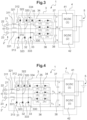
- Charger 1 is identical to that of the picture 3 , except for the modifications indicated below.
- the charger 1 comprises in the power factor correction stage 3 a first additional switch Q1 installed between the controlled switch assemblies 34, 35, 36 and the output midpoint M of the power factor correction stage .
- the charger 1 also includes in the power factor correction stage 3 a second additional switch Q2 mounted between the controlled switch assemblies 34, 35, 36 and the negative output terminal N.
- the charger can recharge the battery from the three-phase electrical network 2 ', in the same way as a charger comprising a Vienna rectifier of the prior art.
- the charger 1 can then operate in energy restitution, by transferring the electrical current accumulated in the battery 5 to the three-phase electrical network 2' using the two DC-DC 41, 42 of the DC-DC conversion stage 4.
- the DC-DC 41 (42) controls the voltage at the terminals of the capacitor 37 (28) to a voltage greater than half the peak voltage between phases of the electrical network 2'.
- the bidirectional MOSFETs 312, 322, 334 and the controlled switches 34, 35, 36 form a three-phase bridge inverter (DC/AC converter) controlled in pulse width modulation (PWM) known to those skilled in the art.
- the charger 1 can be operated in restitution mode with the same power as that available in charging mode, for example at powers of 22 kW.
- Such a charger 1 comprising the two additional switches Q1, Q2 could be adapted to the charger of the figure 2 , connected to a single-phase electrical network 2, by positioning the two additional switches Q1 and Q2 at the same locations in the power factor correction stage 3.
Landscapes
- Engineering & Computer Science (AREA)
- Power Engineering (AREA)
- Transportation (AREA)
- Mechanical Engineering (AREA)
- Charge And Discharge Circuits For Batteries Or The Like (AREA)
- Rectifiers (AREA)
Claims (7)
- Ladegerät (1) für einen elektrischen Akkumulator (5) für ein Elektrokraftfahrzeug, das dazu fähig ist, eine elektrische Wechselspannung zu empfangen und diese in eine Gleichspannung zum Wiederaufladen des Akkumulators (5) umzuwandeln, wobei das Ladegerät (1) eine Leistungsfaktor-Korrekturstufe (3) und eine Gleichstrom-Gleichstrom-Umwandlungsstufe (4) beinhaltet, wobei die Leistungsfaktor-Korrekturstufe (3) einen Vienna-Gleichrichter (3) beinhaltet, der mindestens drei Brückenarme (31, 32, 33) umfasst, die sich jeweils zwischen zwei Ausgangsanschlüssen (P, N) der Leistungsfaktor-Korrekturstufe (3) erstrecken,wobei jeder Brückenarm (31, 32, 33) dazu fähig ist, an einem Mittelpunkt (310, 320, 330) über eine Induktivität (311, 321, 331) mit einer Phase (21, 22, 23) eines elektrischen Netzes (2) verbunden zu sein,wobei der Vienna-Gleichrichter (3) für jeden Brückenarm (31, 32, 33) eine Anordnung gesteuerter Schalter (34, 35, 36) beinhaltet, die einerseits mit dem Mittelpunkt (310, 320, 330) des entsprechenden Brückenarms (31, 32, 33) und andererseits mit einem Ausgangsmittelpunkt (M) der Leistungsfaktor-Korrekturstufe (3) verbunden ist;wobei für jeden Ausgangsanschluss (P, N) der Leistungsfaktor-Korrekturstufe (3) ein Ausgangskondensator (37, 38) zwischen den entsprechenden Ausgangsanschluss (P, N) und den Ausgangsmittelpunkt (M) der Leistungsfaktor-Korrekturstufe (3) geschaltet ist, dadurch gekennzeichnet, dass mindestens zwei Brückenarme (31, 32) des Vienna-Gleichrichters (3) jeweils einen einzelnen bidirektionalen Isolierschicht-Feldeffekttransistor (312, 322, 334) und eine Diode (313, 323, 333) beinhalten, die zu beiden Seiten des Mittelpunkts (310, 320) des entsprechenden Brückenarms (31, 32) geschaltet sind; und dass die Gleichstrom-Gleichstrom-Umwandlungsstufe (4) zwei Gleichstrom-Gleichstrom-Umwandlungsvorrichtungen (41, 42) beinhaltet, die jeweils am Eingang parallel zu einem der Ausgangskondensatoren (37, 38) der Leistungsfaktor-Korrekturstufe (3) und am Ausgang mit den Anschlüssen des Akkumulators (5) verbunden sind, sodass das Ladegerät (1) dazu fähig ist, das Fließen eines elektrischen Stroms von dem Akkumulator (5) zu dem elektrischen Netz (2) zu gestatten, und dass es einen zusätzlichen ersten Schalter (Q1), der zwischen den Anordnungen gesteuerter Schalter (34, 35, 36) und dem Ausgangsmittelpunkt (M) der Leistungsfaktor-Korrekturstufe (3) installiert ist, und einen zusätzlichen zweiten Schalter (Q2), der zwischen die Anordnungen gesteuerter Schalter (34, 35, 36) und einen Ausgangsanschluss (N) der Leistungsfaktor-Korrekturstufe (3) geschaltet ist, beinhaltet, sodass, wenn der zusätzliche erste Schalter (Q1) geschlossen ist und der zusätzliche zweite Schalter (Q2) geöffnet ist, das Ladegerät (1) dazu fähig ist, den Akkumulator (5) von dem elektrischen Netz (2, 2') aus wiederaufzuladen, und, wenn der zusätzliche erste Schalter (Q1) geöffnet ist und der zusätzliche zweite Schalter (Q2) geschlossen ist, das Ladegerät (1) dazu fähig ist, die in dem Akkumulator (5) gespeicherte Energie an das elektrische Netz (2, 2') zu übertragen, unter Verwendung der zwei Gleichstrom-Gleichstrom-Wandler (41, 42) der Gleichstrom-Gleichstrom-Umwandlungsstufe (4).
- Ladegerät (1) für einen Akkumulator (5) nach Anspruch 1, dadurch gekennzeichnet, dass zwei Brückenarme (31, 32) dazu bestimmt sind, mit einer Phase (21) eines einphasigen elektrischen Netzes (2) verbunden zu sein, wobei nur die zwei Brückenarme (31, 32) einen Isolierschicht-Feldeffekttransistor (312, 322) und eine Diode (313, 323) beinhalten, die zu beiden Seiten des Mittelpunkts (310, 320) des entsprechenden Brückenarms (31, 32) geschaltet sind.
- Ladegerät (1) für einen Akkumulator (5) nach Anspruch 1 oder 2, dadurch gekennzeichnet, dass drei Brückenarme (31, 32, 33) dazu bestimmt sind, jeweils mit einer Phase (21, 22, 23) eines dreiphasigen elektrischen Netzes (2') verbunden zu sein, wobei jeder der drei Brückenarme (31, 32, 33) einen Isolierschicht-Feldeffekttransistor (312, 322, 334) und eine Diode (313, 323, 333) beinhaltet, die zu beiden Seiten des Mittelpunkts (310, 320, 330) des entsprechenden Brückenarms (31, 32, 33) geschaltet sind.
- Ladegerät (1) für einen Akkumulator (5) nach Anspruch 1, dadurch gekennzeichnet, dass mindestens ein bidirektionaler Isolierschicht-Feldeffekttransistor (312, 322, 334) einen bidirektionalen Metall-Oxid-Feldeffekttransistor (MOSFET) beinhaltet.
- Ladegerät (1) für einen Akkumulator (5) nach Anspruch 1 oder 2, dadurch gekennzeichnet, dass die Anordnungen gesteuerter Schalter (34, 35, 36) jeweils zwei Leistungs-Metall-Oxid-Feldeffekttransistoren (MOSFET) beinhalten, die mit zueinander entgegengesetzter Polarität geschaltet sind.
- Ladegerät (1) für einen Akkumulator (5) nach einem beliebigen der Ansprüche 1 bis 5, dadurch gekennzeichnet, dass mindestens ein Gleichstrom-Gleichstrom-Wandler (41, 42) so ausgelegt ist, dass er mit einer Leistung von 11 kW arbeiten kann.
- Elektrokraftfahrzeug, das einen elektrischen Akkumulator (5) und ein Ladegerät (1) für einen Akkumulator (5) nach einem beliebigen der Ansprüche 1 bis 6 beinhaltet.
Applications Claiming Priority (2)
| Application Number | Priority Date | Filing Date | Title |
|---|---|---|---|
| FR1750251A FR3061819B1 (fr) | 2017-01-12 | 2017-01-12 | Chargeur de batterie d'accumulateurs electriques bidirectionnel. |
| PCT/FR2018/050042 WO2018130773A1 (fr) | 2017-01-12 | 2018-01-09 | Chargeur de batterie d'accumulateurs électriques bidirectionnel |
Publications (2)
| Publication Number | Publication Date |
|---|---|
| EP3568905A1 EP3568905A1 (de) | 2019-11-20 |
| EP3568905B1 true EP3568905B1 (de) | 2023-03-08 |
Family
ID=58669942
Family Applications (1)
| Application Number | Title | Priority Date | Filing Date |
|---|---|---|---|
| EP18703046.5A Active EP3568905B1 (de) | 2017-01-12 | 2018-01-09 | Bidirektionales ladegerät für elektrischen akkumulator |
Country Status (4)
| Country | Link |
|---|---|
| EP (1) | EP3568905B1 (de) |
| CN (1) | CN110612658B (de) |
| FR (1) | FR3061819B1 (de) |
| WO (1) | WO2018130773A1 (de) |
Cited By (2)
| Publication number | Priority date | Publication date | Assignee | Title |
|---|---|---|---|---|
| WO2025114074A1 (de) * | 2023-11-29 | 2025-06-05 | Zf Friedrichshafen Ag | Ladeschaltung für ein elektrisch antreibbares kraftfahrzeug |
| US12489361B2 (en) | 2023-04-17 | 2025-12-02 | Nxp B.V. | Bidirectional power converter with phase leg fault detection for charging a battery that powers a multiphase load |
Families Citing this family (19)
| Publication number | Priority date | Publication date | Assignee | Title |
|---|---|---|---|---|
| EP3648322A1 (de) * | 2018-10-30 | 2020-05-06 | Mahle International GmbH | Bordladegeräte (obc) |
| FR3089721B1 (fr) | 2018-12-07 | 2021-09-17 | Renault Sas | Dispositif de charge réversible pour véhicule automobile |
| KR102682808B1 (ko) * | 2019-03-26 | 2024-07-10 | 현대자동차주식회사 | 양방향 완속 충전기 및 그 제어 방법 |
| NL2022950B1 (en) * | 2019-04-15 | 2020-10-22 | Prodrive Tech Bv | Electrical Converter |
| WO2020221807A1 (en) * | 2019-05-02 | 2020-11-05 | Prodrive Technologies B.V. | Electrical converter |
| NL2023292B1 (en) * | 2019-06-12 | 2021-01-21 | Prodrive Tech Bv | Electrical Converter |
| CN113412566B (zh) | 2019-05-24 | 2024-06-04 | 华为数字能源技术有限公司 | 包括变压器和多电平功率变换器的集成充电和电机控制系统 |
| CN110350796B (zh) * | 2019-06-25 | 2020-11-06 | 华为技术有限公司 | 一种功率转换模块、车载充电机和电动汽车 |
| CN110356268B (zh) * | 2019-06-25 | 2021-08-03 | 华为技术有限公司 | 一种车载充放电装置和系统 |
| AT523199B1 (de) * | 2019-12-12 | 2022-09-15 | Avl List Gmbh | Stromrichtervorrichtung, Testsystem, sowie Verfahren zum Ansteuern einer Stromrichtervorrichtung |
| CN114337332B (zh) * | 2020-09-30 | 2023-12-22 | 重庆美的制冷设备有限公司 | 三相电源变换电路、电路控制方法、线路板及空调器 |
| CN115250075B (zh) * | 2021-04-26 | 2025-05-27 | 佛山市顺德区美的电子科技有限公司 | 一种三相电源变换电路、家电设备、控制方法及装置 |
| CN113991794B (zh) * | 2021-11-08 | 2024-12-10 | 苏州汇川联合动力系统股份有限公司 | 电池充电电路及方法 |
| FR3138589A1 (fr) | 2022-08-01 | 2024-02-02 | Renault S.A.S | Procédé de commande d’un chargeur électrique bidirectionnel |
| FI131169B1 (en) * | 2022-08-09 | 2024-11-15 | Lappeenrannan Lahden Teknillinen Yliopisto Lut | System and method of an electrochemical process |
| CN117977945A (zh) * | 2022-10-25 | 2024-05-03 | 邯郸美的制冷设备有限公司 | 三相电源变换电路的控制方法、装置、设备和存储介质 |
| TWI862211B (zh) * | 2023-10-12 | 2024-11-11 | 台達電子工業股份有限公司 | 功率因數校正轉換器 |
| DE102023210505A1 (de) * | 2023-10-25 | 2025-04-30 | Volkswagen Aktiengesellschaft | Traktionsnetz für ein Kraftfahrzeug |
| DE102023212363B3 (de) | 2023-12-07 | 2024-12-05 | Volkswagen Aktiengesellschaft | Traktionsnetz für ein Kraftfahrzeug |
Family Cites Families (3)
| Publication number | Priority date | Publication date | Assignee | Title |
|---|---|---|---|---|
| CN102739100B (zh) * | 2012-06-11 | 2014-09-10 | 合肥工业大学 | 三电平三相四桥臂变流器 |
| CN102891611B (zh) * | 2012-06-30 | 2014-10-08 | 华为技术有限公司 | 五电平功率变换器及其控制方法、控制装置 |
| CN105762919A (zh) * | 2016-04-22 | 2016-07-13 | 刘昊洋 | 一种基于光伏的充电系统 |
-
2017
- 2017-01-12 FR FR1750251A patent/FR3061819B1/fr not_active Expired - Fee Related
-
2018
- 2018-01-09 EP EP18703046.5A patent/EP3568905B1/de active Active
- 2018-01-09 CN CN201880006757.8A patent/CN110612658B/zh active Active
- 2018-01-09 WO PCT/FR2018/050042 patent/WO2018130773A1/fr not_active Ceased
Non-Patent Citations (1)
| Title |
|---|
| YU FANG ET AL: "Study on bidirectional-charger for electric vehicle applied to power dispatching in smart grid", 2016 IEEE 8TH INTERNATIONAL POWER ELECTRONICS AND MOTION CONTROL CONFERENCE (IPEMC-ECCE ASIA), IEEE, 22 May 2016 (2016-05-22), pages 2709 - 2713, XP032924713, DOI: 10.1109/IPEMC.2016.7512726 * |
Cited By (2)
| Publication number | Priority date | Publication date | Assignee | Title |
|---|---|---|---|---|
| US12489361B2 (en) | 2023-04-17 | 2025-12-02 | Nxp B.V. | Bidirectional power converter with phase leg fault detection for charging a battery that powers a multiphase load |
| WO2025114074A1 (de) * | 2023-11-29 | 2025-06-05 | Zf Friedrichshafen Ag | Ladeschaltung für ein elektrisch antreibbares kraftfahrzeug |
Also Published As
| Publication number | Publication date |
|---|---|
| CN110612658A (zh) | 2019-12-24 |
| WO2018130773A1 (fr) | 2018-07-19 |
| EP3568905A1 (de) | 2019-11-20 |
| CN110612658B (zh) | 2022-12-09 |
| FR3061819A1 (fr) | 2018-07-13 |
| FR3061819B1 (fr) | 2021-06-18 |
Similar Documents
| Publication | Publication Date | Title |
|---|---|---|
| EP3568905B1 (de) | Bidirektionales ladegerät für elektrischen akkumulator | |
| EP3554887B1 (de) | Steuerungsverfahren einer in einem elektrischen oder hybriden fahrzeug eingebetteten ladevorrichtung | |
| EP3607644B1 (de) | Verfahren zur steuerung einer aufladevorrichtung an bord eines elektro- oder hybridfahrzeugs | |
| EP3386087B1 (de) | Einphasiges und dreiphasiges elektrisches ladesystem für ein elektro- oder hybridfahrzeug | |
| WO2015101594A2 (fr) | Convertisseur d'energie multi-sorties a commande par dephasage | |
| EP3602767A1 (de) | Gleichspannungswandler | |
| WO2022214745A1 (fr) | Dispositif de creation d'un bus de tension continue pour un systeme electrique polyphase, vehicule automobile et generateur a energie renouvelable comprenant un tel dispositif | |
| EP3515749A1 (de) | Umwandlungsvorrichtung, zugehöriges steuerungsverfahren und zugehöriges fahrzeug | |
| EP3171505B1 (de) | Ladevorrichtung für eine zugbatterie eines kraftfahrzeugs mit einem zumindest teilweise elektrischen antrieb | |
| FR3089721A1 (fr) | Dispositif de charge réversible pour véhicule automobile | |
| FR3036864A1 (fr) | Dispositif electrique multifonction | |
| FR3026242A1 (fr) | Dispositif combine de charge d'une batterie et d'alimentation electrique d'une machine electrique | |
| FR3074984A1 (fr) | Convertisseur continu-continu avec pre-charge d’un premier reseau electrique a partir d’un deuxieme reseau electrique | |
| EP3707800B1 (de) | Verfahren zur steuerung eines batterieladegerätes für elektrische akkumulatoren | |
| EP3685485B1 (de) | Verfahren zur steuerung eines ladesystems einer traktionbatterie | |
| FR3001843A1 (fr) | Dispositif et procede correspondant de gestion de batteries de vehicule automobile, en particulier une batterie basse tension et une batterie haute tension | |
| EP3276810B1 (de) | Isolierter dc-dc-wandler und elektrische batterie, die einen solchen isolierten dc-dc-wandler umfasst | |
| FR3078212A1 (fr) | Convertisseur dc-dc pour chargeur bidirectionnel. | |
| EP3966922B1 (de) | Mehrstufiger spannungswandler mit optimierter zusätzlicher energiespeicherung | |
| FR3089076A1 (fr) | Convertisseur courant continu - courant continu résonant de type LLC | |
| EP3276812B1 (de) | Isolierter dc-dc-wandler und elektrische batterie, die einen solchen isolierten dc-dc-wandler umfasst | |
| FR3082683A1 (fr) | Convertisseur bidirectionnel pour vehicule electrique ou hybride | |
| WO2023094701A1 (fr) | Convertisseur de puissance présentant un module de découplage | |
| FR3029715B1 (fr) | Convertisseur electrique continu-continu comprenant un circuit limiteur de tension | |
| WO2024115185A1 (fr) | Systeme electrique d'alimentation pour vehicule |
Legal Events
| Date | Code | Title | Description |
|---|---|---|---|
| STAA | Information on the status of an ep patent application or granted ep patent |
Free format text: STATUS: UNKNOWN |
|
| STAA | Information on the status of an ep patent application or granted ep patent |
Free format text: STATUS: THE INTERNATIONAL PUBLICATION HAS BEEN MADE |
|
| PUAI | Public reference made under article 153(3) epc to a published international application that has entered the european phase |
Free format text: ORIGINAL CODE: 0009012 |
|
| STAA | Information on the status of an ep patent application or granted ep patent |
Free format text: STATUS: REQUEST FOR EXAMINATION WAS MADE |
|
| 17P | Request for examination filed |
Effective date: 20190711 |
|
| AK | Designated contracting states |
Kind code of ref document: A1 Designated state(s): AL AT BE BG CH CY CZ DE DK EE ES FI FR GB GR HR HU IE IS IT LI LT LU LV MC MK MT NL NO PL PT RO RS SE SI SK SM TR |
|
| AX | Request for extension of the european patent |
Extension state: BA ME |
|
| DAV | Request for validation of the european patent (deleted) | ||
| DAX | Request for extension of the european patent (deleted) | ||
| STAA | Information on the status of an ep patent application or granted ep patent |
Free format text: STATUS: EXAMINATION IS IN PROGRESS |
|
| 17Q | First examination report despatched |
Effective date: 20200604 |
|
| RAP3 | Party data changed (applicant data changed or rights of an application transferred) |
Owner name: NISSAN MOTOR CO., LTD. Owner name: RENAULT S.A.S |
|
| RAP3 | Party data changed (applicant data changed or rights of an application transferred) |
Owner name: NISSAN MOTOR CO., LTD. Owner name: RENAULT S.A.S |
|
| REG | Reference to a national code |
Ref country code: DE Ref legal event code: R079 Ref document number: 602018046930 Country of ref document: DE Free format text: PREVIOUS MAIN CLASS: H02M0001420000 Ipc: H02M0007487000 |
|
| GRAP | Despatch of communication of intention to grant a patent |
Free format text: ORIGINAL CODE: EPIDOSNIGR1 |
|
| STAA | Information on the status of an ep patent application or granted ep patent |
Free format text: STATUS: GRANT OF PATENT IS INTENDED |
|
| RIC1 | Information provided on ipc code assigned before grant |
Ipc: H02J 7/02 20160101ALI20220906BHEP Ipc: H02M 7/219 20060101ALI20220906BHEP Ipc: H02M 7/797 20060101ALI20220906BHEP Ipc: H02M 1/42 20070101ALI20220906BHEP Ipc: B60L 55/00 20190101ALI20220906BHEP Ipc: B60L 53/22 20190101ALI20220906BHEP Ipc: B60L 1/00 20060101ALI20220906BHEP Ipc: H02M 7/487 20070101AFI20220906BHEP |
|
| INTG | Intention to grant announced |
Effective date: 20220922 |
|
| GRAS | Grant fee paid |
Free format text: ORIGINAL CODE: EPIDOSNIGR3 |
|
| GRAA | (expected) grant |
Free format text: ORIGINAL CODE: 0009210 |
|
| STAA | Information on the status of an ep patent application or granted ep patent |
Free format text: STATUS: THE PATENT HAS BEEN GRANTED |
|
| AK | Designated contracting states |
Kind code of ref document: B1 Designated state(s): AL AT BE BG CH CY CZ DE DK EE ES FI FR GB GR HR HU IE IS IT LI LT LU LV MC MK MT NL NO PL PT RO RS SE SI SK SM TR |
|
| REG | Reference to a national code |
Ref country code: CH Ref legal event code: EP Ref country code: AT Ref legal event code: REF Ref document number: 1553268 Country of ref document: AT Kind code of ref document: T Effective date: 20230315 |
|
| REG | Reference to a national code |
Ref country code: DE Ref legal event code: R096 Ref document number: 602018046930 Country of ref document: DE |
|
| REG | Reference to a national code |
Ref country code: IE Ref legal event code: FG4D Free format text: LANGUAGE OF EP DOCUMENT: FRENCH |
|
| REG | Reference to a national code |
Ref country code: LT Ref legal event code: MG9D |
|
| REG | Reference to a national code |
Ref country code: NL Ref legal event code: MP Effective date: 20230308 |
|
| PG25 | Lapsed in a contracting state [announced via postgrant information from national office to epo] |
Ref country code: RS Free format text: LAPSE BECAUSE OF FAILURE TO SUBMIT A TRANSLATION OF THE DESCRIPTION OR TO PAY THE FEE WITHIN THE PRESCRIBED TIME-LIMIT Effective date: 20230308 Ref country code: NO Free format text: LAPSE BECAUSE OF FAILURE TO SUBMIT A TRANSLATION OF THE DESCRIPTION OR TO PAY THE FEE WITHIN THE PRESCRIBED TIME-LIMIT Effective date: 20230608 Ref country code: LV Free format text: LAPSE BECAUSE OF FAILURE TO SUBMIT A TRANSLATION OF THE DESCRIPTION OR TO PAY THE FEE WITHIN THE PRESCRIBED TIME-LIMIT Effective date: 20230308 Ref country code: LT Free format text: LAPSE BECAUSE OF FAILURE TO SUBMIT A TRANSLATION OF THE DESCRIPTION OR TO PAY THE FEE WITHIN THE PRESCRIBED TIME-LIMIT Effective date: 20230308 Ref country code: HR Free format text: LAPSE BECAUSE OF FAILURE TO SUBMIT A TRANSLATION OF THE DESCRIPTION OR TO PAY THE FEE WITHIN THE PRESCRIBED TIME-LIMIT Effective date: 20230308 Ref country code: ES Free format text: LAPSE BECAUSE OF FAILURE TO SUBMIT A TRANSLATION OF THE DESCRIPTION OR TO PAY THE FEE WITHIN THE PRESCRIBED TIME-LIMIT Effective date: 20230308 |
|
| REG | Reference to a national code |
Ref country code: AT Ref legal event code: MK05 Ref document number: 1553268 Country of ref document: AT Kind code of ref document: T Effective date: 20230308 |
|
| PG25 | Lapsed in a contracting state [announced via postgrant information from national office to epo] |
Ref country code: SE Free format text: LAPSE BECAUSE OF FAILURE TO SUBMIT A TRANSLATION OF THE DESCRIPTION OR TO PAY THE FEE WITHIN THE PRESCRIBED TIME-LIMIT Effective date: 20230308 Ref country code: NL Free format text: LAPSE BECAUSE OF FAILURE TO SUBMIT A TRANSLATION OF THE DESCRIPTION OR TO PAY THE FEE WITHIN THE PRESCRIBED TIME-LIMIT Effective date: 20230308 Ref country code: GR Free format text: LAPSE BECAUSE OF FAILURE TO SUBMIT A TRANSLATION OF THE DESCRIPTION OR TO PAY THE FEE WITHIN THE PRESCRIBED TIME-LIMIT Effective date: 20230609 Ref country code: FI Free format text: LAPSE BECAUSE OF FAILURE TO SUBMIT A TRANSLATION OF THE DESCRIPTION OR TO PAY THE FEE WITHIN THE PRESCRIBED TIME-LIMIT Effective date: 20230308 |
|
| PG25 | Lapsed in a contracting state [announced via postgrant information from national office to epo] |
Ref country code: SM Free format text: LAPSE BECAUSE OF FAILURE TO SUBMIT A TRANSLATION OF THE DESCRIPTION OR TO PAY THE FEE WITHIN THE PRESCRIBED TIME-LIMIT Effective date: 20230308 Ref country code: RO Free format text: LAPSE BECAUSE OF FAILURE TO SUBMIT A TRANSLATION OF THE DESCRIPTION OR TO PAY THE FEE WITHIN THE PRESCRIBED TIME-LIMIT Effective date: 20230308 Ref country code: PT Free format text: LAPSE BECAUSE OF FAILURE TO SUBMIT A TRANSLATION OF THE DESCRIPTION OR TO PAY THE FEE WITHIN THE PRESCRIBED TIME-LIMIT Effective date: 20230710 Ref country code: EE Free format text: LAPSE BECAUSE OF FAILURE TO SUBMIT A TRANSLATION OF THE DESCRIPTION OR TO PAY THE FEE WITHIN THE PRESCRIBED TIME-LIMIT Effective date: 20230308 Ref country code: CZ Free format text: LAPSE BECAUSE OF FAILURE TO SUBMIT A TRANSLATION OF THE DESCRIPTION OR TO PAY THE FEE WITHIN THE PRESCRIBED TIME-LIMIT Effective date: 20230308 Ref country code: AT Free format text: LAPSE BECAUSE OF FAILURE TO SUBMIT A TRANSLATION OF THE DESCRIPTION OR TO PAY THE FEE WITHIN THE PRESCRIBED TIME-LIMIT Effective date: 20230308 |
|
| PG25 | Lapsed in a contracting state [announced via postgrant information from national office to epo] |
Ref country code: SK Free format text: LAPSE BECAUSE OF FAILURE TO SUBMIT A TRANSLATION OF THE DESCRIPTION OR TO PAY THE FEE WITHIN THE PRESCRIBED TIME-LIMIT Effective date: 20230308 Ref country code: PL Free format text: LAPSE BECAUSE OF FAILURE TO SUBMIT A TRANSLATION OF THE DESCRIPTION OR TO PAY THE FEE WITHIN THE PRESCRIBED TIME-LIMIT Effective date: 20230308 Ref country code: IS Free format text: LAPSE BECAUSE OF FAILURE TO SUBMIT A TRANSLATION OF THE DESCRIPTION OR TO PAY THE FEE WITHIN THE PRESCRIBED TIME-LIMIT Effective date: 20230708 |
|
| REG | Reference to a national code |
Ref country code: DE Ref legal event code: R097 Ref document number: 602018046930 Country of ref document: DE |
|
| PLBE | No opposition filed within time limit |
Free format text: ORIGINAL CODE: 0009261 |
|
| STAA | Information on the status of an ep patent application or granted ep patent |
Free format text: STATUS: NO OPPOSITION FILED WITHIN TIME LIMIT |
|
| PG25 | Lapsed in a contracting state [announced via postgrant information from national office to epo] |
Ref country code: SI Free format text: LAPSE BECAUSE OF FAILURE TO SUBMIT A TRANSLATION OF THE DESCRIPTION OR TO PAY THE FEE WITHIN THE PRESCRIBED TIME-LIMIT Effective date: 20230308 Ref country code: DK Free format text: LAPSE BECAUSE OF FAILURE TO SUBMIT A TRANSLATION OF THE DESCRIPTION OR TO PAY THE FEE WITHIN THE PRESCRIBED TIME-LIMIT Effective date: 20230308 |
|
| 26N | No opposition filed |
Effective date: 20231211 |
|
| PG25 | Lapsed in a contracting state [announced via postgrant information from national office to epo] |
Ref country code: IT Free format text: LAPSE BECAUSE OF FAILURE TO SUBMIT A TRANSLATION OF THE DESCRIPTION OR TO PAY THE FEE WITHIN THE PRESCRIBED TIME-LIMIT Effective date: 20230308 |
|
| REG | Reference to a national code |
Ref country code: DE Ref legal event code: R081 Ref document number: 602018046930 Country of ref document: DE Owner name: NISSAN MOTOR CO., LTD., YOKOHAMA-SHI, JP Free format text: FORMER OWNERS: NISSAN MOTOR CO., LTD., YOKOHAMA-SHI, KANAGAWA, JP; RENAULT S.A.S., BOULOGNE BILLANCOURT, FR Ref country code: DE Ref legal event code: R081 Ref document number: 602018046930 Country of ref document: DE Owner name: AMPERE S.A.S., FR Free format text: FORMER OWNERS: NISSAN MOTOR CO., LTD., YOKOHAMA-SHI, KANAGAWA, JP; RENAULT S.A.S., BOULOGNE BILLANCOURT, FR |
|
| PG25 | Lapsed in a contracting state [announced via postgrant information from national office to epo] |
Ref country code: MC Free format text: LAPSE BECAUSE OF FAILURE TO SUBMIT A TRANSLATION OF THE DESCRIPTION OR TO PAY THE FEE WITHIN THE PRESCRIBED TIME-LIMIT Effective date: 20230308 |
|
| PG25 | Lapsed in a contracting state [announced via postgrant information from national office to epo] |
Ref country code: MC Free format text: LAPSE BECAUSE OF FAILURE TO SUBMIT A TRANSLATION OF THE DESCRIPTION OR TO PAY THE FEE WITHIN THE PRESCRIBED TIME-LIMIT Effective date: 20230308 |
|
| REG | Reference to a national code |
Ref country code: CH Ref legal event code: PL |
|
| PG25 | Lapsed in a contracting state [announced via postgrant information from national office to epo] |
Ref country code: LU Free format text: LAPSE BECAUSE OF NON-PAYMENT OF DUE FEES Effective date: 20240109 |
|
| PG25 | Lapsed in a contracting state [announced via postgrant information from national office to epo] |
Ref country code: LU Free format text: LAPSE BECAUSE OF NON-PAYMENT OF DUE FEES Effective date: 20240109 |
|
| PG25 | Lapsed in a contracting state [announced via postgrant information from national office to epo] |
Ref country code: BE Free format text: LAPSE BECAUSE OF NON-PAYMENT OF DUE FEES Effective date: 20240131 |
|
| PG25 | Lapsed in a contracting state [announced via postgrant information from national office to epo] |
Ref country code: CH Free format text: LAPSE BECAUSE OF NON-PAYMENT OF DUE FEES Effective date: 20240131 |
|
| PG25 | Lapsed in a contracting state [announced via postgrant information from national office to epo] |
Ref country code: CH Free format text: LAPSE BECAUSE OF NON-PAYMENT OF DUE FEES Effective date: 20240131 Ref country code: BE Free format text: LAPSE BECAUSE OF NON-PAYMENT OF DUE FEES Effective date: 20240131 |
|
| REG | Reference to a national code |
Ref country code: BE Ref legal event code: MM Effective date: 20240131 |
|
| PG25 | Lapsed in a contracting state [announced via postgrant information from national office to epo] |
Ref country code: BG Free format text: LAPSE BECAUSE OF FAILURE TO SUBMIT A TRANSLATION OF THE DESCRIPTION OR TO PAY THE FEE WITHIN THE PRESCRIBED TIME-LIMIT Effective date: 20230308 |
|
| PG25 | Lapsed in a contracting state [announced via postgrant information from national office to epo] |
Ref country code: BG Free format text: LAPSE BECAUSE OF FAILURE TO SUBMIT A TRANSLATION OF THE DESCRIPTION OR TO PAY THE FEE WITHIN THE PRESCRIBED TIME-LIMIT Effective date: 20230308 |
|
| PG25 | Lapsed in a contracting state [announced via postgrant information from national office to epo] |
Ref country code: IE Free format text: LAPSE BECAUSE OF NON-PAYMENT OF DUE FEES Effective date: 20240109 |
|
| PG25 | Lapsed in a contracting state [announced via postgrant information from national office to epo] |
Ref country code: IE Free format text: LAPSE BECAUSE OF NON-PAYMENT OF DUE FEES Effective date: 20240109 |
|
| REG | Reference to a national code |
Ref country code: GB Ref legal event code: 732E Free format text: REGISTERED BETWEEN 20250501 AND 20250507 |
|
| PG25 | Lapsed in a contracting state [announced via postgrant information from national office to epo] |
Ref country code: CY Free format text: LAPSE BECAUSE OF FAILURE TO SUBMIT A TRANSLATION OF THE DESCRIPTION OR TO PAY THE FEE WITHIN THE PRESCRIBED TIME-LIMIT; INVALID AB INITIO Effective date: 20180109 |
|
| PG25 | Lapsed in a contracting state [announced via postgrant information from national office to epo] |
Ref country code: HU Free format text: LAPSE BECAUSE OF FAILURE TO SUBMIT A TRANSLATION OF THE DESCRIPTION OR TO PAY THE FEE WITHIN THE PRESCRIBED TIME-LIMIT; INVALID AB INITIO Effective date: 20180109 |
|
| PG25 | Lapsed in a contracting state [announced via postgrant information from national office to epo] |
Ref country code: TR Free format text: LAPSE BECAUSE OF FAILURE TO SUBMIT A TRANSLATION OF THE DESCRIPTION OR TO PAY THE FEE WITHIN THE PRESCRIBED TIME-LIMIT Effective date: 20230308 |
|
| PGFP | Annual fee paid to national office [announced via postgrant information from national office to epo] |
Ref country code: GB Payment date: 20260123 Year of fee payment: 9 |
|
| PGFP | Annual fee paid to national office [announced via postgrant information from national office to epo] |
Ref country code: DE Payment date: 20260121 Year of fee payment: 9 |
|
| PGFP | Annual fee paid to national office [announced via postgrant information from national office to epo] |
Ref country code: FR Payment date: 20260123 Year of fee payment: 9 |