EP3568702B1 - Verfahren und system zur durchführung der erkennung auf, oder charakterisierung einer probe - Google Patents
Verfahren und system zur durchführung der erkennung auf, oder charakterisierung einer probe Download PDFInfo
- Publication number
- EP3568702B1 EP3568702B1 EP18702348.6A EP18702348A EP3568702B1 EP 3568702 B1 EP3568702 B1 EP 3568702B1 EP 18702348 A EP18702348 A EP 18702348A EP 3568702 B1 EP3568702 B1 EP 3568702B1
- Authority
- EP
- European Patent Office
- Prior art keywords
- sample
- probe
- atomic force
- vibration
- modulation
- Prior art date
- Legal status (The legal status is an assumption and is not a legal conclusion. Google has not performed a legal analysis and makes no representation as to the accuracy of the status listed.)
- Active
Links
Images




Classifications
-
- G—PHYSICS
- G01—MEASURING; TESTING
- G01N—INVESTIGATING OR ANALYSING MATERIALS BY DETERMINING THEIR CHEMICAL OR PHYSICAL PROPERTIES
- G01N29/00—Investigating or analysing materials by the use of ultrasonic, sonic or infrasonic waves; Visualisation of the interior of objects by transmitting ultrasonic or sonic waves through the object
- G01N29/04—Analysing solids
- G01N29/06—Visualisation of the interior, e.g. acoustic microscopy
- G01N29/0654—Imaging
- G01N29/0681—Imaging by acoustic microscopy, e.g. scanning acoustic microscopy
-
- G—PHYSICS
- G01—MEASURING; TESTING
- G01Q—SCANNING-PROBE TECHNIQUES OR APPARATUS; APPLICATIONS OF SCANNING-PROBE TECHNIQUES, e.g. SCANNING PROBE MICROSCOPY [SPM]
- G01Q60/00—Particular types of SPM [Scanning Probe Microscopy] or microscopes; Essential components thereof
- G01Q60/24—AFM [Atomic Force Microscopy] or apparatus therefor, e.g. AFM probes
- G01Q60/32—AC mode
-
- G—PHYSICS
- G01—MEASURING; TESTING
- G01N—INVESTIGATING OR ANALYSING MATERIALS BY DETERMINING THEIR CHEMICAL OR PHYSICAL PROPERTIES
- G01N21/00—Investigating or analysing materials by the use of optical means, i.e. using sub-millimetre waves, infrared, visible or ultraviolet light
- G01N21/17—Systems in which incident light is modified in accordance with the properties of the material investigated
- G01N21/1702—Systems in which incident light is modified in accordance with the properties of the material investigated with opto-acoustic detection, e.g. for gases or analysing solids
-
- G—PHYSICS
- G01—MEASURING; TESTING
- G01N—INVESTIGATING OR ANALYSING MATERIALS BY DETERMINING THEIR CHEMICAL OR PHYSICAL PROPERTIES
- G01N29/00—Investigating or analysing materials by the use of ultrasonic, sonic or infrasonic waves; Visualisation of the interior of objects by transmitting ultrasonic or sonic waves through the object
- G01N29/04—Analysing solids
- G01N29/041—Analysing solids on the surface of the material, e.g. using Lamb, Rayleigh or shear waves
-
- G—PHYSICS
- G01—MEASURING; TESTING
- G01N—INVESTIGATING OR ANALYSING MATERIALS BY DETERMINING THEIR CHEMICAL OR PHYSICAL PROPERTIES
- G01N29/00—Investigating or analysing materials by the use of ultrasonic, sonic or infrasonic waves; Visualisation of the interior of objects by transmitting ultrasonic or sonic waves through the object
- G01N29/22—Details, e.g. general constructional or apparatus details
- G01N29/24—Probes
- G01N29/2418—Probes using optoacoustic interaction with the material, e.g. laser radiation, photoacoustics
-
- G—PHYSICS
- G01—MEASURING; TESTING
- G01N—INVESTIGATING OR ANALYSING MATERIALS BY DETERMINING THEIR CHEMICAL OR PHYSICAL PROPERTIES
- G01N29/00—Investigating or analysing materials by the use of ultrasonic, sonic or infrasonic waves; Visualisation of the interior of objects by transmitting ultrasonic or sonic waves through the object
- G01N29/22—Details, e.g. general constructional or apparatus details
- G01N29/26—Arrangements for orientation or scanning by relative movement of the head and the sensor
- G01N29/265—Arrangements for orientation or scanning by relative movement of the head and the sensor by moving the sensor relative to a stationary material
-
- G—PHYSICS
- G01—MEASURING; TESTING
- G01Q—SCANNING-PROBE TECHNIQUES OR APPARATUS; APPLICATIONS OF SCANNING-PROBE TECHNIQUES, e.g. SCANNING PROBE MICROSCOPY [SPM]
- G01Q60/00—Particular types of SPM [Scanning Probe Microscopy] or microscopes; Essential components thereof
- G01Q60/24—AFM [Atomic Force Microscopy] or apparatus therefor, e.g. AFM probes
- G01Q60/38—Probes, their manufacture, or their related instrumentation, e.g. holders
-
- G—PHYSICS
- G01—MEASURING; TESTING
- G01N—INVESTIGATING OR ANALYSING MATERIALS BY DETERMINING THEIR CHEMICAL OR PHYSICAL PROPERTIES
- G01N2291/00—Indexing codes associated with group G01N29/00
- G01N2291/26—Scanned objects
- G01N2291/263—Surfaces
Definitions
- the present invention is directed at a method for mapping surface and subsurface characteristics of a sample.
- the invention is further directed at a method for performing atomic force microscopy, and at an atomic force microscopy system.
- subsurface probe microscopy also known as subsurface AFM
- Subsurface AFM is typically operated in contact-mode feedback wherein a topography image is obtained using contact-mode feedback of the low-frequency ( ⁇ 2 kHz) portion of the cantilever deflection signal, while simultaneously recording a subsurface image from the high frequency amplitude and phase at modulation frequency.
- the subsurface AFM Since the subsurface AFM is operated in the contact mode, it has the disadvantages that it can damage the sample, especially since higher force application is needed to get high signal to noise ratios.
- Nonlinear detection of ultrasonic vibration of AFM cantilevers in and out of contact with the sample relates to ultrasonic force microscopy.
- Publication US6305226B1 describes a method and apparatus for imaging acoustic fields in high-frequency acoustic resonators.
- Publication " Mapping nanoscale domain patterns in ferroelectric ceramics by atomic force acoustic microscopy and piezoresponse force microscopy” by Zhou et al. (DOI: 10.1063/1.4801976 ) describes techniques for determining properties of ferroelectric ceramics.
- an atomic force microscope comprising: a probe comprising a probe tip configured to sense a sample disposed proximate to the probe tip, a detector to detect a deflection of the probe tip, an actuator coupled to the probe and configured to move the probe in a sense state with the sample at a predetermined force set point and an acoustic vibrator in communication with the sample to provide a vibration to the sample, the vibration comprising a modulation frequency, wherein the acoustic vibrator is configured to provide the vibration in a modulation period after an initial sense for carrying out a measurement without modulation and wherein the probe is moved during or after said modulation period to a successive sample position over said sample while moving the probe in a non-contact state.
- a method for performing atomic force microscopy comprising providing an atomic force microscope comprising a probe configured to sense a sample disposed proximate to the probe, a sample disposed proximate to the probe, and a vibrator in communication with the sample to provide a vibration to the sample, the vibration comprising a modulation frequency, subjecting the sample to the vibration and modulating the sample at the modulation frequency to perform atomic force microscopy, wherein the vibration is provided in a modulation period after an initial sense period for carrying out a measurement without modulation and wherein the probe is moved during or after said modulation period to a successive sample position over said sample while moving the probe in a non-contact state.
- a non-resonant cantilever probe that first reaches a surface with a defined set point force, carries out a measurement in an initial sense period without modulation and subsequently after capturing the topography information, collecting subsurface information in a modulation period of the vibrator subsequent to the initial sense period.
- the initial sense period the surface topology is measured at a fixed set point force in either contact or non-contact region (see Figure 2 ), by lowering the cantilever probe from a fixed z- height.
- subsurface measurements can be carried out with vibrations in MHz range, to measure viscoelastic contract mechanism. This modulation period can be measured at a second contact force afterwards but is in the contact region. Normally, for reasons of efficiency both topography and subsurface will be measured at the same set point force (in a repulsive, contact region).
- Subsurface measurements carried out in GHz range to measure a wave propagation contrast mechanism can be carried out in the non-contact region. For efficiency preferably at the same force as the topography measurement.
- the cantilever In between the phases, where the probe is moved to a new successive sample position, the cantilever is retracted to the fixed z-height.
- Approaching and retraction can be carried out with conventional means, eg. a piezo element or by direct actuation on the cantilever (electrostatically or thermally). Such methods may have a smaller z-range however, this need not be limiting in this application.
- This method may have the following advantages: during a sub-surface measurement the probe is positioned near the surface and requires a certain measurement time at a pixel. In this phase a continuous amplitude/frequency modulation is not suitable. Also contact-mode AFM is not suitable, because it damages the surface while moving laterally. In contrast to the prior art, the deformation forces on the sample are now minimized. In particular, shear forces are minimized, as the sample is not moved during the time the tip is in contact - so shear forces are substantially zero. Deformation in z can still be large (may be needed for viscoelastic subsurface imaging) but can be well controlled to be below damaging threshold. When a large step is encountered in the profile of a sample, e.g.
- the required scanning volume in amplitude/frequency modulation mode can be high. Therefore the mode requires a measurement frequency below the resonant frequency, or a combination between 'slow' approach and small amplitude frequency/amplitude modulation.
- corrections can be carried out during a single approach curve.
- Conventional peak force tapping in contrast only does feedback in between curves based on 'peak force' during a previous curve.
- this new mode correction is done for the current measurement pixel and not only for the next measurement pixel as in conventional peak-force tapping mode.
- the present invention provides an atomic force microscopy (AFM) method with an ultrasonic force microscopy (UFM), or a heterodyne force microscopy (HFM), or other atomic force acoustic microscopy method to simultaneously perform binding strength measurements and surface topography mapping.
- AFM atomic force microscopy
- UFM ultrasonic force microscopy
- HFM heterodyne force microscopy
- the present invention performs AFM by scanning the surface of the element with a probe, while additionally applying an acoustic vibration signal to the semiconductor element using a transducer.
- the present detection method enables to provide a stiffness map of the sample, a surface topography of the sample, or a combination. It can provide a three-dimensional stiffness or visco elasticity of the sample.
- the method may be performed at high throughput.
- the step of monitoring the probe tip motion for mapping the surface of the semiconductor element comprises at least one of: using a first fraction of the output signal, wherein the first fraction of the output signal at least includes output signal components having a frequency below a first frequency; or using a feedback signal indicative of height corrections of the probe tip relative to the surface of the sample; or obtaining, using a z-level sensor, height measurements of the height of the probe tip relative to the samplesurface.
- an analyzer system or control system analyzes a first fraction of the output signal which includes low frequency (and also DC or static) signal components, to obtain the required information for performing surface topography mapping.
- Such information may be obtained from a feedback signal that controls the height of the scan head or the probe above the surface and from which height corrections may be obtained.
- Another option is to use an additional z-level sensor to measure the height of the probe or the height corrections.
- the acoustic vibration signal comprises a carrier wave signal having a carrier frequency and a modulation signal having a modulation frequency.
- the modulation frequency may be controlled such as to optimize an output signal strength of the output signal. This may be performed optionally in combination with the tuning of the setpoint force value as explained above.
- the tuning of the modulation frequency to the setpoint force is based on the insight that by changing the setpoint force value, the contact resonance frequency also changes.
- the contact resonance frequency at a certain setpoint may for example be found by sweeping the modulation frequency across a plurality of modulation frequency values, and monitoring the demodulation amplitude or demodulation phase of the output signal.
- the optimal modulation frequency associated with each setpoint force value may be found.
- the method further comprises, at one or more positions of the probe tip relative to the semiconductor element, the steps of controlling a setpoint force such as to consecutively set the setpoint force at a plurality of setpoint force values, and performing, at each setpoint force value, a frequency sweep of the modulation frequency across a plurality of frequencies in a frequency range for associating an optimal modulation frequency with each setpoint force value.
- UFM ultrasonic force microscopy
- the set point force is controlled such as to set the measurement depth to an interface region between the self assembled monolayer and a lower portion or layer of the semiconductor element, to enable simultaneous detection of surface defect and binding strength of the monolayer.
- the semiconductor element comprises at least one of a substrate or one or more device layers, wherein an upper layer of the semiconductor element is provided by the self-assembled monolayer, and wherein the method is performed to simultaneously detect surface defects in the self-assembled monolayer and map a position dependent contact stiffness indicative of a binding strength of the self-assembled monolayer to the semiconductor device.
- FIG. 1 schematically illustrates an atomic force microscopy system (AFM) 1, suitable for use in a method of the present invention and in accordance with an embodiment of the present invention.
- the system 1 comprises a probe 3 having a cantilever 4 and a probe tip 5.
- the probe tip 5 is brought in contact with a surface of a sample 12.
- a light source 7, typically a laser, provides an optical signal beam 8 that is incident on the back of the probe tip 5.
- a reflected optical beam 9 is received by an optical sensor 10. Any vibration of the probe tip 5 perpendicular to the surface sample 12 will result in a deflection of the reflected optical beam 9. This deflection can be accurately determined by means of optical sensor 10 which provides an (electrical) output signal 39 for further analysis.
- the detection method of the present invention applies, in addition to performing surface topography measurements, an acoustic vibration signal to the sample 12, which results in acoustic vibrations at its surface. These vibrations may be sensed by the probe tip 5 with great accuracy.
- a vibrator 20 is arranged underneath the sample 12.
- a coupling medium 21 e.g. a liquid, an oil or grease (e.g. vaseline)
- the vibrator 20 for applying the acoustic vibration signal may be located elsewhere relative to the semiconductor element 12, enabling the acoustic vibration signal to be applied from any desired direction (e.g. above, below, from aside, or even through another part or entity).
- the acoustic vibration signal 50 to be provided via the transducer 20 to the semiconductor element 12 consists of a high frequency component f 1 and a low frequency component f 2 , and is created as follows.
- One or more signal generators comprise at least first frequency generator 25, a second frequency generator 26, and a signal mixer 28.
- a high frequency input signal component f 1 25 and a low frequency input signal component f 2 26 are mixed by mixer 28 and provided to the transducer 20.
- the transducer 20, via the coupling medium 21 (which in the present example may be Vaseline), sends the acoustic vibration signal into the sample 12.
- the sensor signal from optical sensor 10 is provided to a low-pass filter 30 for contact mode feedback, and the output of the low-pass filter 30 is sent to the feedback control system 31.
- the low pass filter 30 has a cutoff frequency of, for example, around 2 kHz. This is fast enough with respect to the scanning speed, but only slightly higher than the sampling rate (e.g. 1024 pixels in 1 second corresponds to a sampling rate of 1.024 kHz).
- Feedback control system 31 uses the feedback signal to maintain the AFM system fixed at its setpoint force.
- the output signal 39 from the optical sensor 10 is further provided to a high-pass filter 34.
- the high pass filter 34 also has a cutoff frequency of, for example, around 2 kHz, thus thereby transmitting the second fraction of the output signal 39 including the high frequency ultrasound signal (i.e. including component f 1 ) and the low frequency modulation signal (i.e. including component f 2 ) to the demodulator 35.
- the demodulator 35 further receives the low frequency input signal f 2 26 as a reference signal from the signal generator 29.
- An output signal of the demodulator 35 is provided to analysis system 38 which allows to analyze the location dependent ultrasound output signal to obtain the subsurface measurement information on the contact stiffness, for enabling binding strength analysis.
- Frequency generators 25 and 26, mixer 28, demodulator 35, and optionally analysis system 38 may form an integral system.
- Figure 2 shows in more detail the typical force diagram that is registered by the cantilever probe tip 5 in approaching sample 12.
- the attractive force approaches zero.
- the probe tip registers an attractive force, that disappears in the contact region.
- the force becomes repulsive and substantially increases.
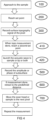
- a new subsurface AFM mode is proposed as following in Figure 3 .
- the probe tip 5 is not resonating and approaches the sample.
- it has a predefined distance from the sample and it approaches the sample until it reaches a set point force 200. Accordingly the height difference is then recorded as the topography information of that pixel.
- the sample is not moving as it stands still.
- an acoustic wave is launched either to sample or tip or both to capture a subsurface signal of the said pixel, which is recorded in a step 500.
- the cantilever retracts in the next step 600 to the predefined initial distance and the sample or the head moves in step 700 to a next pixel. This process is repeated for as many pixels as need be recorded.
- steps 100-300 are identical. Instead of launching the acoustic wave at the designated set point reached in step 200, another set point is reached in step 410. This second set point can be at a higher or lower force set point than the initial first force set point. Subsequently an acoustic wave is launched to the sample or tip or both, in step 420. Subsequently steps 500 -700 are identical to steps in Figure 3 .
- Figure 5 a further variation is shown.
- the measurement steps 430, 440 and 500 are repeated at another set point force.
- This set point force may be higher or lower than the second set point force.
- steps of Figure 3 and 5 are combined, for example, a first measurement is carried out at a set point force (step 430) identical to the surface topography recording step 200.
- FIG 6 a trace diagram is shown for a calculated subsurface mode according to the above steps (for convenience, only this mode is shown).
- the assumptions are that a measurement cycle is about 1 ms.
- the controller 31 moves the cantilever probe tip over a height of 30nm towards the sample on a new pixel position.
- the tip thus moves (at zero force) away from the surface by 30nm, i.e. in this period the force is 0nN.
- the feedback Upon hitting the sample, the feedback has an overshoot, to -300nN before reaching the setpoint at -100nN.
- the force changes from about 100 nN to zero N when in the subsurface phase with a peak force of less than 300 nN (nano Newton).
- a sub surface measurement is performed in phase 500.
- the controller 31 moves the cantilever probe tip of 30nm.
- the vibrator is provided by an acoustic piezo transducer coupled to the sample.
- the cantilever tip can be vibrated.
- the corresponding dynamic model parameters for the model are
Landscapes
- Physics & Mathematics (AREA)
- General Physics & Mathematics (AREA)
- Health & Medical Sciences (AREA)
- General Health & Medical Sciences (AREA)
- Chemical & Material Sciences (AREA)
- Analytical Chemistry (AREA)
- Biochemistry (AREA)
- Life Sciences & Earth Sciences (AREA)
- Immunology (AREA)
- Pathology (AREA)
- Acoustics & Sound (AREA)
- Nuclear Medicine, Radiotherapy & Molecular Imaging (AREA)
- Radiology & Medical Imaging (AREA)
- Optics & Photonics (AREA)
- Engineering & Computer Science (AREA)
- Power Engineering (AREA)
- Investigating Or Analyzing Materials By The Use Of Ultrasonic Waves (AREA)
- Analysing Materials By The Use Of Radiation (AREA)
Claims (12)
- Rasterkraftmikroskop (1), umfassend:- eine Sonde (3) mit einer Sondenspitze (5), die so konfiguriert ist, dass sie eine Probe (12) abtastet, die in der Nähe der Sondenspitze (5) angeordnet ist; einen Detektor zur Erfassung einer Auslenkung der Sondenspitze (5);- einen Aktuator, der mit der Sonde (3) gekoppelt und so konfiguriert ist, dass er die Sonde (3) in einem Abtastzustand mit der Probe bei einem ersten vorbestimmten Kraftsollwert bewegt; und- einen akustischen Vibrator (20), der mit der Probe (12) in Verbindung steht, um die Probe (12) in Schwingung zu versetzen, wobei die Schwingung eine Modulationsfrequenz umfasst,- wobei der akustische Vibrator (20) so konfiguriert ist, dass er die Vibration in einer Modulationsperiode bereitstellt, wobei die Modulationsperiode auf eine anfängliche Abtastperiode zur Durchführung einer Messung ohne Modulation folgt; und- wobei das Rasterkraftmikroskop (1) so konfiguriert ist, dass es die Sonde (3) während oder nach der Modulationsperiode zu einer aufeinanderfolgenden Probenposition über die besagte Probe (12) bewegt, während die Sonde (3) in einem berührungslosen Zustand bewegt wird.
- Rasterkraftmikroskop nach Anspruch 1, wobei der Aktuator so konfiguriert ist, dass er die Sonde (3) in einem Abtastzustand mit der Probe (12) bei einem zweiten Kraftsollwert, der sich vom ersten Sollwert unterscheidet, in der Modulationsperiode hält.
- Rasterkraftmikroskop nach Anspruch 1, wobei der akustische Vibrator (20) einen mechanischen Wandler (20) umfasst.
- Rasterkraftmikroskop nach Anspruch 2, wobei der mechanische Wandler (20) einen piezoelektrischen Wandler (20) umfasst.
- Rasterkraftmikroskop nach Anspruch 1, wobei das Rasterkraftmikroskop (1) so konfiguriert ist, dass es die Probe (12) in einer zweidimensionalen Ebene verschiebt.
- Rasterkraftmikroskop nach Anspruch 1, wobei das Rasterkraftmikroskop (1) so konfiguriert ist, dass es eine Steifigkeitskarte der Probe (12), eine Oberflächentopographie der Probe (12) oder eine Kombination, die mindestens eines der vorgenannten Elemente umfasst, bereitstellt.
- Rasterkraftmikroskop nach Anspruch 1, wobei das Rasterkraftmikroskop (1) so konfiguriert ist, dass es eine dreidimensionale Steifigkeit oder Viskoelastizität der Probe (12) bereitstellt.
- Verfahren zur Durchführung von Rasterkraftmikroskopie, wobei das Verfahren umfasst:- Bereitstellung eines Rasterkraftmikroskops (1), das Folgendes umfasst: eine Sonde (3), die so konfiguriert ist, dass sie eine in der Nähe der Sonde (3) angeordnete Probe (12) bei einem ersten Kraftsollwert abtastet; eine Probe (12), die in der Nähe der Sonde (3) angeordnet ist; und einen Vibrator (20) in Verbindung mit der Probe (12), um die Probe (12) in Schwingung zu versetzen, wobei die Schwingung eine Modulationsfrequenz umfasst,- Abtasten der Probe (12) durch die besagte Sonde (3) am ersten Kraftsollwert in einer anfänglichen Abtastperiode, um eine Messung ohne Modulation durchzuführen;- Aussetzen der Probe (12) der Vibration in einer Modulationsperiode nach der anfänglichen Abtastperiode ohne Modulation; wodurch die Probe (12) mit der Modulationsfrequenz moduliert wird, um eine Charakterisierung der Oberfläche oder des Untergrunds der Probe (12) durchzuführen,- wobei die Sonde (3) während oder nach der Modulationsperiode zu einer aufeinanderfolgenden Probenposition über die Probe (12) bewegt wird, während die Sonde (3) in einem Nicht-Kontaktzustand bewegt wird.
- Verfahren nach Anspruch 8, wobei die Probe (12) einer Vibration ausgesetzt wird, während die Probe (12), die sich in der Nähe der Sonde (3) befindet, am ersten Kraftsollwert abgetastet wird.
- Verfahren nach Anspruch 8, wobei die Probe (12) einer Vibration ausgesetzt wird, während die Probe (12), die sich in der Nähe der Sonde (3) befindet, bei einem anderen Kraftsollwert, der sich von dem ersten Sollwert unterscheidet, gemessen wird.
- Verfahren nach Anspruch 8, wobei der Schritt des Abtastens der Auslenkung der Sondenspitze (5) mindestens einen der folgenden Schritte umfasst:- Verwendung eines Bruchteils eines Detektorausgangssignals; oder- Verwendung eines Rückkopplungssignals, das Höhenkorrekturen der Sondenspitze (5) relativ zur Oberfläche des Halbleiterelements (12) anzeigt; oder- Erlangung von Höhenmessungen der Höhe der Sondenspitze (5) relativ zur Oberfläche des Halbleiterelements (12) mit Hilfe eines Z-Level-Sensors.
- Verfahren nach einem der vorhergehenden Ansprüche, wobei der Schritt des Anwendens der Vibration auf die Probe (12) durch Anwenden eines akustischen Vibrationssignals durch den Vibrator (20) direkt auf die Probe (12) durchgeführt wird, wie beispielsweise über mindestens einen der folgenden Schritte: eine Kontaktfläche unterhalb der Probe (12), eine Oberseite der Probe (12), oder die Seite der Probe (12).
Applications Claiming Priority (2)
| Application Number | Priority Date | Filing Date | Title |
|---|---|---|---|
| EP17151429.2A EP3349019A1 (de) | 2017-01-13 | 2017-01-13 | Verfahren und system zur durchführung der erkennung auf, oder charakterisierung einer probe |
| PCT/NL2018/050020 WO2018132005A1 (en) | 2017-01-13 | 2018-01-11 | Method of and system for performing detection on or characterization of a sample |
Publications (2)
| Publication Number | Publication Date |
|---|---|
| EP3568702A1 EP3568702A1 (de) | 2019-11-20 |
| EP3568702B1 true EP3568702B1 (de) | 2024-01-10 |
Family
ID=57796255
Family Applications (2)
| Application Number | Title | Priority Date | Filing Date |
|---|---|---|---|
| EP17151429.2A Withdrawn EP3349019A1 (de) | 2017-01-13 | 2017-01-13 | Verfahren und system zur durchführung der erkennung auf, oder charakterisierung einer probe |
| EP18702348.6A Active EP3568702B1 (de) | 2017-01-13 | 2018-01-11 | Verfahren und system zur durchführung der erkennung auf, oder charakterisierung einer probe |
Family Applications Before (1)
| Application Number | Title | Priority Date | Filing Date |
|---|---|---|---|
| EP17151429.2A Withdrawn EP3349019A1 (de) | 2017-01-13 | 2017-01-13 | Verfahren und system zur durchführung der erkennung auf, oder charakterisierung einer probe |
Country Status (5)
| Country | Link |
|---|---|
| US (1) | US10948458B2 (de) |
| EP (2) | EP3349019A1 (de) |
| KR (1) | KR102577416B1 (de) |
| TW (1) | TWI812608B (de) |
| WO (1) | WO2018132005A1 (de) |
Families Citing this family (6)
| Publication number | Priority date | Publication date | Assignee | Title |
|---|---|---|---|---|
| EP3404424A1 (de) * | 2017-05-15 | 2018-11-21 | Nederlandse Organisatie voor toegepast- natuurwetenschappelijk onderzoek TNO | Rastersondenmikroskopiesystem und verfahren zur abbildung von nanostrukturen auf der oberfläche einer probe |
| FR3098918B1 (fr) * | 2019-07-16 | 2022-01-21 | Paris Sciences Lettres Quartier Latin | Microscope a force atomique |
| WO2021145034A1 (ja) * | 2020-01-17 | 2021-07-22 | 株式会社島津製作所 | 欠陥検査装置および欠陥検査方法 |
| JP7529350B2 (ja) * | 2020-09-24 | 2024-08-06 | パーク システムズ コーポレーション | 可変的なセットポイント設定を使用して測定装置により測定対象の表面の特性を測定する方法、この方法が遂行されるための原子顕微鏡及びこの方法が遂行されるために格納媒体に格納されたコンピュータプログラム |
| KR102761512B1 (ko) * | 2020-09-24 | 2025-02-04 | 파크시스템스 주식회사 | 가변적인 셋포인트 설정을 사용하여 측정 장치에 의해 측정 대상의 표면의 특성을 측정하는 방법, 이 방법이 수행되기 위한 원자 현미경 및 이 방법이 수행되기 위해 저장 매체에 저장된 컴퓨터 프로그램 |
| WO2026018229A1 (en) * | 2024-07-16 | 2026-01-22 | Shilps Sciences Private Limited | A method for enhancement of a signal in acoustic assisted afm imaging |
Family Cites Families (9)
| Publication number | Priority date | Publication date | Assignee | Title |
|---|---|---|---|---|
| DE4324983C2 (de) * | 1993-07-26 | 1996-07-11 | Fraunhofer Ges Forschung | Akustisches Mikroskop |
| US6075585A (en) * | 1994-04-12 | 2000-06-13 | The Board Of Trustees Of The Leland Stanford, Jr. University | Vibrating probe for a scanning probe microscope |
| US5948972A (en) * | 1994-12-22 | 1999-09-07 | Kla-Tencor Corporation | Dual stage instrument for scanning a specimen |
| US6305226B1 (en) * | 1999-08-30 | 2001-10-23 | Agere Systems Guardian Corp. | Method and apparatus for imaging acoustic fields in high-frequency acoustic resonators |
| KR101112505B1 (ko) * | 2010-05-17 | 2012-02-14 | 서울과학기술대학교 산학협력단 | 초음파 원자현미경장치 |
| US8895923B2 (en) * | 2012-11-20 | 2014-11-25 | Dcg Systems, Inc. | System and method for non-contact microscopy for three-dimensional pre-characterization of a sample for fast and non-destructive on sample navigation during nanoprobing |
| TWI515434B (zh) * | 2013-03-21 | 2016-01-01 | 國立清華大學 | 帶電探針及其電場量測方法 |
| US9535085B2 (en) | 2014-08-05 | 2017-01-03 | The United States Of America, As Represented By The Secretary Of Commerce | Intermittent contact resonance atomic force microscope and process for intermittent contact resonance atomic force microscopy |
| WO2016205257A1 (en) * | 2015-06-15 | 2016-12-22 | Dcg Systems, Inc. | Diamond delayering for electrical probing |
-
2017
- 2017-01-13 EP EP17151429.2A patent/EP3349019A1/de not_active Withdrawn
-
2018
- 2018-01-11 KR KR1020197022714A patent/KR102577416B1/ko active Active
- 2018-01-11 US US16/477,280 patent/US10948458B2/en active Active
- 2018-01-11 EP EP18702348.6A patent/EP3568702B1/de active Active
- 2018-01-11 WO PCT/NL2018/050020 patent/WO2018132005A1/en not_active Ceased
- 2018-01-12 TW TW107101281A patent/TWI812608B/zh active
Also Published As
| Publication number | Publication date |
|---|---|
| EP3568702A1 (de) | 2019-11-20 |
| WO2018132005A1 (en) | 2018-07-19 |
| KR20190107049A (ko) | 2019-09-18 |
| US20190383774A1 (en) | 2019-12-19 |
| TW201831910A (zh) | 2018-09-01 |
| EP3349019A1 (de) | 2018-07-18 |
| TWI812608B (zh) | 2023-08-21 |
| US10948458B2 (en) | 2021-03-16 |
| KR102577416B1 (ko) | 2023-09-12 |
Similar Documents
| Publication | Publication Date | Title |
|---|---|---|
| US10948458B2 (en) | Method of and system for performing detection on or characterization of a sample | |
| US7055378B2 (en) | System for wide frequency dynamic nanomechanical analysis | |
| US7373806B2 (en) | Scanning probe microscope and scanning method | |
| EP0839312B1 (de) | Tapping-modus-atomkraftmikroskop mit phasen- oder frequenzdetektion | |
| USRE36488E (en) | Tapping atomic force microscope with phase or frequency detection | |
| US20160313367A1 (en) | Method and Apparatus of Operating a Scanning Probe Microscope | |
| JP2003227788A (ja) | 走査型プローブ顕微鏡及び試料の表面構造測定方法 | |
| RU2005102703A (ru) | Сканирующий зондовый микроскоп | |
| JPH0626855A (ja) | 原子間力顕微鏡 | |
| US9535085B2 (en) | Intermittent contact resonance atomic force microscope and process for intermittent contact resonance atomic force microscopy | |
| JP4496350B2 (ja) | 原子間力顕微鏡 | |
| JP2010210609A (ja) | 走査型プローブ顕微鏡における探針とサンプルの近接方法 | |
| EP3443363B1 (de) | Verfahren zur abstimmung von parametereinstellungen zum ausführen von akustischer rastersondenmikroskopie zur abbildung von unteroberflächenformationen, rastersondenmikroskopiesystem und computerprogrammprodukt | |
| KR102405671B1 (ko) | 반도체 소자 또는 반가공 반도체 소자의 레이어의 결함 탐지 또는 특성화를 수행하는 방법 및 시스템 | |
| EP2776851B1 (de) | Verfahren und vorrichtung zur einstellung eines rastersondenmikroskops | |
| CN104155477A (zh) | 一种原子力声学显微镜探针接触谐振频率追踪方法 | |
| CN102575975B (zh) | 扫描探针显微镜以及利用扫描探针显微镜扫描材料表面的方法 | |
| CN101317138A (zh) | 图像处理设备、计算机程序产品以及图像处理方法 | |
| US11774381B2 (en) | Method for measuring damage of a substrate caused by an electron beam | |
| US10895584B2 (en) | Method of controlling a probe using constant command signals | |
| JP5553926B2 (ja) | 走査型プローブ顕微鏡における探針とサンプルの近接方法 | |
| EP3422104A1 (de) | Verfahren, atomkraftmikroskopiesystem und computerprogrammprodukt | |
| Marinello et al. | Elastic-properties measurement at high temperatures through contact resonance atomic force microscopy | |
| JP2000329675A (ja) | 走査型プローブ顕微鏡 | |
| JPH09281118A (ja) | 走査型プローブ顕微鏡 |
Legal Events
| Date | Code | Title | Description |
|---|---|---|---|
| STAA | Information on the status of an ep patent application or granted ep patent |
Free format text: STATUS: UNKNOWN |
|
| STAA | Information on the status of an ep patent application or granted ep patent |
Free format text: STATUS: THE INTERNATIONAL PUBLICATION HAS BEEN MADE |
|
| PUAI | Public reference made under article 153(3) epc to a published international application that has entered the european phase |
Free format text: ORIGINAL CODE: 0009012 |
|
| STAA | Information on the status of an ep patent application or granted ep patent |
Free format text: STATUS: REQUEST FOR EXAMINATION WAS MADE |
|
| 17P | Request for examination filed |
Effective date: 20190801 |
|
| AK | Designated contracting states |
Kind code of ref document: A1 Designated state(s): AL AT BE BG CH CY CZ DE DK EE ES FI FR GB GR HR HU IE IS IT LI LT LU LV MC MK MT NL NO PL PT RO RS SE SI SK SM TR |
|
| AX | Request for extension of the european patent |
Extension state: BA ME |
|
| DAV | Request for validation of the european patent (deleted) | ||
| DAX | Request for extension of the european patent (deleted) | ||
| STAA | Information on the status of an ep patent application or granted ep patent |
Free format text: STATUS: EXAMINATION IS IN PROGRESS |
|
| 17Q | First examination report despatched |
Effective date: 20210630 |
|
| P01 | Opt-out of the competence of the unified patent court (upc) registered |
Effective date: 20230522 |
|
| GRAP | Despatch of communication of intention to grant a patent |
Free format text: ORIGINAL CODE: EPIDOSNIGR1 |
|
| STAA | Information on the status of an ep patent application or granted ep patent |
Free format text: STATUS: GRANT OF PATENT IS INTENDED |
|
| INTG | Intention to grant announced |
Effective date: 20230725 |
|
| GRAS | Grant fee paid |
Free format text: ORIGINAL CODE: EPIDOSNIGR3 |
|
| GRAA | (expected) grant |
Free format text: ORIGINAL CODE: 0009210 |
|
| STAA | Information on the status of an ep patent application or granted ep patent |
Free format text: STATUS: THE PATENT HAS BEEN GRANTED |
|
| AK | Designated contracting states |
Kind code of ref document: B1 Designated state(s): AL AT BE BG CH CY CZ DE DK EE ES FI FR GB GR HR HU IE IS IT LI LT LU LV MC MK MT NL NO PL PT RO RS SE SI SK SM TR |
|
| REG | Reference to a national code |
Ref country code: GB Ref legal event code: FG4D |
|
| REG | Reference to a national code |
Ref country code: CH Ref legal event code: EP |
|
| REG | Reference to a national code |
Ref country code: DE Ref legal event code: R096 Ref document number: 602018063928 Country of ref document: DE |
|
| REG | Reference to a national code |
Ref country code: IE Ref legal event code: FG4D |
|
| REG | Reference to a national code |
Ref country code: NL Ref legal event code: FP |
|
| REG | Reference to a national code |
Ref country code: LT Ref legal event code: MG9D |
|
| REG | Reference to a national code |
Ref country code: AT Ref legal event code: MK05 Ref document number: 1649305 Country of ref document: AT Kind code of ref document: T Effective date: 20240110 |
|
| PG25 | Lapsed in a contracting state [announced via postgrant information from national office to epo] |
Ref country code: IS Free format text: LAPSE BECAUSE OF FAILURE TO SUBMIT A TRANSLATION OF THE DESCRIPTION OR TO PAY THE FEE WITHIN THE PRESCRIBED TIME-LIMIT Effective date: 20240510 |
|
| PG25 | Lapsed in a contracting state [announced via postgrant information from national office to epo] |
Ref country code: LT Free format text: LAPSE BECAUSE OF FAILURE TO SUBMIT A TRANSLATION OF THE DESCRIPTION OR TO PAY THE FEE WITHIN THE PRESCRIBED TIME-LIMIT Effective date: 20240110 |
|
| PG25 | Lapsed in a contracting state [announced via postgrant information from national office to epo] |
Ref country code: GR Free format text: LAPSE BECAUSE OF FAILURE TO SUBMIT A TRANSLATION OF THE DESCRIPTION OR TO PAY THE FEE WITHIN THE PRESCRIBED TIME-LIMIT Effective date: 20240411 |
|
| PG25 | Lapsed in a contracting state [announced via postgrant information from national office to epo] |
Ref country code: RS Free format text: LAPSE BECAUSE OF FAILURE TO SUBMIT A TRANSLATION OF THE DESCRIPTION OR TO PAY THE FEE WITHIN THE PRESCRIBED TIME-LIMIT Effective date: 20240410 Ref country code: HR Free format text: LAPSE BECAUSE OF FAILURE TO SUBMIT A TRANSLATION OF THE DESCRIPTION OR TO PAY THE FEE WITHIN THE PRESCRIBED TIME-LIMIT Effective date: 20240110 |
|
| PG25 | Lapsed in a contracting state [announced via postgrant information from national office to epo] |
Ref country code: ES Free format text: LAPSE BECAUSE OF FAILURE TO SUBMIT A TRANSLATION OF THE DESCRIPTION OR TO PAY THE FEE WITHIN THE PRESCRIBED TIME-LIMIT Effective date: 20240110 |
|
| PG25 | Lapsed in a contracting state [announced via postgrant information from national office to epo] |
Ref country code: AT Free format text: LAPSE BECAUSE OF FAILURE TO SUBMIT A TRANSLATION OF THE DESCRIPTION OR TO PAY THE FEE WITHIN THE PRESCRIBED TIME-LIMIT Effective date: 20240110 |
|
| PG25 | Lapsed in a contracting state [announced via postgrant information from national office to epo] |
Ref country code: RS Free format text: LAPSE BECAUSE OF FAILURE TO SUBMIT A TRANSLATION OF THE DESCRIPTION OR TO PAY THE FEE WITHIN THE PRESCRIBED TIME-LIMIT Effective date: 20240410 Ref country code: NO Free format text: LAPSE BECAUSE OF FAILURE TO SUBMIT A TRANSLATION OF THE DESCRIPTION OR TO PAY THE FEE WITHIN THE PRESCRIBED TIME-LIMIT Effective date: 20240410 Ref country code: LT Free format text: LAPSE BECAUSE OF FAILURE TO SUBMIT A TRANSLATION OF THE DESCRIPTION OR TO PAY THE FEE WITHIN THE PRESCRIBED TIME-LIMIT Effective date: 20240110 Ref country code: IS Free format text: LAPSE BECAUSE OF FAILURE TO SUBMIT A TRANSLATION OF THE DESCRIPTION OR TO PAY THE FEE WITHIN THE PRESCRIBED TIME-LIMIT Effective date: 20240510 Ref country code: HR Free format text: LAPSE BECAUSE OF FAILURE TO SUBMIT A TRANSLATION OF THE DESCRIPTION OR TO PAY THE FEE WITHIN THE PRESCRIBED TIME-LIMIT Effective date: 20240110 Ref country code: GR Free format text: LAPSE BECAUSE OF FAILURE TO SUBMIT A TRANSLATION OF THE DESCRIPTION OR TO PAY THE FEE WITHIN THE PRESCRIBED TIME-LIMIT Effective date: 20240411 Ref country code: ES Free format text: LAPSE BECAUSE OF FAILURE TO SUBMIT A TRANSLATION OF THE DESCRIPTION OR TO PAY THE FEE WITHIN THE PRESCRIBED TIME-LIMIT Effective date: 20240110 Ref country code: BG Free format text: LAPSE BECAUSE OF FAILURE TO SUBMIT A TRANSLATION OF THE DESCRIPTION OR TO PAY THE FEE WITHIN THE PRESCRIBED TIME-LIMIT Effective date: 20240110 Ref country code: AT Free format text: LAPSE BECAUSE OF FAILURE TO SUBMIT A TRANSLATION OF THE DESCRIPTION OR TO PAY THE FEE WITHIN THE PRESCRIBED TIME-LIMIT Effective date: 20240110 |
|
| PG25 | Lapsed in a contracting state [announced via postgrant information from national office to epo] |
Ref country code: PL Free format text: LAPSE BECAUSE OF FAILURE TO SUBMIT A TRANSLATION OF THE DESCRIPTION OR TO PAY THE FEE WITHIN THE PRESCRIBED TIME-LIMIT Effective date: 20240110 Ref country code: PT Free format text: LAPSE BECAUSE OF FAILURE TO SUBMIT A TRANSLATION OF THE DESCRIPTION OR TO PAY THE FEE WITHIN THE PRESCRIBED TIME-LIMIT Effective date: 20240510 |
|
| PG25 | Lapsed in a contracting state [announced via postgrant information from national office to epo] |
Ref country code: SE Free format text: LAPSE BECAUSE OF FAILURE TO SUBMIT A TRANSLATION OF THE DESCRIPTION OR TO PAY THE FEE WITHIN THE PRESCRIBED TIME-LIMIT Effective date: 20240110 Ref country code: PT Free format text: LAPSE BECAUSE OF FAILURE TO SUBMIT A TRANSLATION OF THE DESCRIPTION OR TO PAY THE FEE WITHIN THE PRESCRIBED TIME-LIMIT Effective date: 20240510 Ref country code: PL Free format text: LAPSE BECAUSE OF FAILURE TO SUBMIT A TRANSLATION OF THE DESCRIPTION OR TO PAY THE FEE WITHIN THE PRESCRIBED TIME-LIMIT Effective date: 20240110 Ref country code: LV Free format text: LAPSE BECAUSE OF FAILURE TO SUBMIT A TRANSLATION OF THE DESCRIPTION OR TO PAY THE FEE WITHIN THE PRESCRIBED TIME-LIMIT Effective date: 20240110 |
|
| REG | Reference to a national code |
Ref country code: CH Ref legal event code: PL |
|
| PG25 | Lapsed in a contracting state [announced via postgrant information from national office to epo] |
Ref country code: LU Free format text: LAPSE BECAUSE OF NON-PAYMENT OF DUE FEES Effective date: 20240111 |
|
| PG25 | Lapsed in a contracting state [announced via postgrant information from national office to epo] |
Ref country code: LU Free format text: LAPSE BECAUSE OF NON-PAYMENT OF DUE FEES Effective date: 20240111 |
|
| PG25 | Lapsed in a contracting state [announced via postgrant information from national office to epo] |
Ref country code: DK Free format text: LAPSE BECAUSE OF FAILURE TO SUBMIT A TRANSLATION OF THE DESCRIPTION OR TO PAY THE FEE WITHIN THE PRESCRIBED TIME-LIMIT Effective date: 20240110 |
|
| REG | Reference to a national code |
Ref country code: DE Ref legal event code: R097 Ref document number: 602018063928 Country of ref document: DE |
|
| PG25 | Lapsed in a contracting state [announced via postgrant information from national office to epo] |
Ref country code: SM Free format text: LAPSE BECAUSE OF FAILURE TO SUBMIT A TRANSLATION OF THE DESCRIPTION OR TO PAY THE FEE WITHIN THE PRESCRIBED TIME-LIMIT Effective date: 20240110 |
|
| PG25 | Lapsed in a contracting state [announced via postgrant information from national office to epo] |
Ref country code: BE Free format text: LAPSE BECAUSE OF NON-PAYMENT OF DUE FEES Effective date: 20240131 |
|
| PG25 | Lapsed in a contracting state [announced via postgrant information from national office to epo] |
Ref country code: CH Free format text: LAPSE BECAUSE OF NON-PAYMENT OF DUE FEES Effective date: 20240131 |
|
| PG25 | Lapsed in a contracting state [announced via postgrant information from national office to epo] |
Ref country code: EE Free format text: LAPSE BECAUSE OF FAILURE TO SUBMIT A TRANSLATION OF THE DESCRIPTION OR TO PAY THE FEE WITHIN THE PRESCRIBED TIME-LIMIT Effective date: 20240110 Ref country code: CZ Free format text: LAPSE BECAUSE OF FAILURE TO SUBMIT A TRANSLATION OF THE DESCRIPTION OR TO PAY THE FEE WITHIN THE PRESCRIBED TIME-LIMIT Effective date: 20240110 |
|
| PG25 | Lapsed in a contracting state [announced via postgrant information from national office to epo] |
Ref country code: SK Free format text: LAPSE BECAUSE OF FAILURE TO SUBMIT A TRANSLATION OF THE DESCRIPTION OR TO PAY THE FEE WITHIN THE PRESCRIBED TIME-LIMIT Effective date: 20240110 |
|
| PG25 | Lapsed in a contracting state [announced via postgrant information from national office to epo] |
Ref country code: SM Free format text: LAPSE BECAUSE OF FAILURE TO SUBMIT A TRANSLATION OF THE DESCRIPTION OR TO PAY THE FEE WITHIN THE PRESCRIBED TIME-LIMIT Effective date: 20240110 Ref country code: SK Free format text: LAPSE BECAUSE OF FAILURE TO SUBMIT A TRANSLATION OF THE DESCRIPTION OR TO PAY THE FEE WITHIN THE PRESCRIBED TIME-LIMIT Effective date: 20240110 Ref country code: RO Free format text: LAPSE BECAUSE OF FAILURE TO SUBMIT A TRANSLATION OF THE DESCRIPTION OR TO PAY THE FEE WITHIN THE PRESCRIBED TIME-LIMIT Effective date: 20240110 Ref country code: EE Free format text: LAPSE BECAUSE OF FAILURE TO SUBMIT A TRANSLATION OF THE DESCRIPTION OR TO PAY THE FEE WITHIN THE PRESCRIBED TIME-LIMIT Effective date: 20240110 Ref country code: DK Free format text: LAPSE BECAUSE OF FAILURE TO SUBMIT A TRANSLATION OF THE DESCRIPTION OR TO PAY THE FEE WITHIN THE PRESCRIBED TIME-LIMIT Effective date: 20240110 Ref country code: CZ Free format text: LAPSE BECAUSE OF FAILURE TO SUBMIT A TRANSLATION OF THE DESCRIPTION OR TO PAY THE FEE WITHIN THE PRESCRIBED TIME-LIMIT Effective date: 20240110 Ref country code: CH Free format text: LAPSE BECAUSE OF NON-PAYMENT OF DUE FEES Effective date: 20240131 Ref country code: BE Free format text: LAPSE BECAUSE OF NON-PAYMENT OF DUE FEES Effective date: 20240131 |
|
| REG | Reference to a national code |
Ref country code: BE Ref legal event code: MM Effective date: 20240131 |
|
| PG25 | Lapsed in a contracting state [announced via postgrant information from national office to epo] |
Ref country code: MC Free format text: LAPSE BECAUSE OF FAILURE TO SUBMIT A TRANSLATION OF THE DESCRIPTION OR TO PAY THE FEE WITHIN THE PRESCRIBED TIME-LIMIT Effective date: 20240110 |
|
| PLBE | No opposition filed within time limit |
Free format text: ORIGINAL CODE: 0009261 |
|
| STAA | Information on the status of an ep patent application or granted ep patent |
Free format text: STATUS: NO OPPOSITION FILED WITHIN TIME LIMIT |
|
| PG25 | Lapsed in a contracting state [announced via postgrant information from national office to epo] |
Ref country code: MC Free format text: LAPSE BECAUSE OF FAILURE TO SUBMIT A TRANSLATION OF THE DESCRIPTION OR TO PAY THE FEE WITHIN THE PRESCRIBED TIME-LIMIT Effective date: 20240110 |
|
| PG25 | Lapsed in a contracting state [announced via postgrant information from national office to epo] |
Ref country code: IT Free format text: LAPSE BECAUSE OF FAILURE TO SUBMIT A TRANSLATION OF THE DESCRIPTION OR TO PAY THE FEE WITHIN THE PRESCRIBED TIME-LIMIT Effective date: 20240110 |
|
| 26N | No opposition filed |
Effective date: 20241011 |
|
| GBPC | Gb: european patent ceased through non-payment of renewal fee |
Effective date: 20240410 |
|
| PG25 | Lapsed in a contracting state [announced via postgrant information from national office to epo] |
Ref country code: IT Free format text: LAPSE BECAUSE OF FAILURE TO SUBMIT A TRANSLATION OF THE DESCRIPTION OR TO PAY THE FEE WITHIN THE PRESCRIBED TIME-LIMIT Effective date: 20240110 |
|
| PG25 | Lapsed in a contracting state [announced via postgrant information from national office to epo] |
Ref country code: GB Free format text: LAPSE BECAUSE OF NON-PAYMENT OF DUE FEES Effective date: 20240410 |
|
| PG25 | Lapsed in a contracting state [announced via postgrant information from national office to epo] |
Ref country code: GB Free format text: LAPSE BECAUSE OF NON-PAYMENT OF DUE FEES Effective date: 20240410 |
|
| PG25 | Lapsed in a contracting state [announced via postgrant information from national office to epo] |
Ref country code: SI Free format text: LAPSE BECAUSE OF FAILURE TO SUBMIT A TRANSLATION OF THE DESCRIPTION OR TO PAY THE FEE WITHIN THE PRESCRIBED TIME-LIMIT Effective date: 20240110 |
|
| PG25 | Lapsed in a contracting state [announced via postgrant information from national office to epo] |
Ref country code: CY Free format text: LAPSE BECAUSE OF FAILURE TO SUBMIT A TRANSLATION OF THE DESCRIPTION OR TO PAY THE FEE WITHIN THE PRESCRIBED TIME-LIMIT; INVALID AB INITIO Effective date: 20180111 |
|
| PG25 | Lapsed in a contracting state [announced via postgrant information from national office to epo] |
Ref country code: HU Free format text: LAPSE BECAUSE OF FAILURE TO SUBMIT A TRANSLATION OF THE DESCRIPTION OR TO PAY THE FEE WITHIN THE PRESCRIBED TIME-LIMIT; INVALID AB INITIO Effective date: 20180111 |
|
| PG25 | Lapsed in a contracting state [announced via postgrant information from national office to epo] |
Ref country code: FI Free format text: LAPSE BECAUSE OF FAILURE TO SUBMIT A TRANSLATION OF THE DESCRIPTION OR TO PAY THE FEE WITHIN THE PRESCRIBED TIME-LIMIT Effective date: 20240110 |
|
| PG25 | Lapsed in a contracting state [announced via postgrant information from national office to epo] |
Ref country code: TR Free format text: LAPSE BECAUSE OF FAILURE TO SUBMIT A TRANSLATION OF THE DESCRIPTION OR TO PAY THE FEE WITHIN THE PRESCRIBED TIME-LIMIT Effective date: 20240110 |
|
| PGFP | Annual fee paid to national office [announced via postgrant information from national office to epo] |
Ref country code: NL Payment date: 20260121 Year of fee payment: 9 |
|
| PGFP | Annual fee paid to national office [announced via postgrant information from national office to epo] |
Ref country code: DE Payment date: 20260121 Year of fee payment: 9 Ref country code: IE Payment date: 20260122 Year of fee payment: 9 |
|
| PGFP | Annual fee paid to national office [announced via postgrant information from national office to epo] |
Ref country code: FR Payment date: 20260123 Year of fee payment: 9 |