EP3567705B1 - Stator for electrical machine and method for producing same - Google Patents
Stator for electrical machine and method for producing same Download PDFInfo
- Publication number
- EP3567705B1 EP3567705B1 EP19167759.0A EP19167759A EP3567705B1 EP 3567705 B1 EP3567705 B1 EP 3567705B1 EP 19167759 A EP19167759 A EP 19167759A EP 3567705 B1 EP3567705 B1 EP 3567705B1
- Authority
- EP
- European Patent Office
- Prior art keywords
- stator
- thermally conductive
- temperature sensor
- conductive element
- coil
- Prior art date
- Legal status (The legal status is an assumption and is not a legal conclusion. Google has not performed a legal analysis and makes no representation as to the accuracy of the status listed.)
- Active
Links
- 238000004519 manufacturing process Methods 0.000 title claims description 9
- 239000004020 conductor Substances 0.000 claims description 52
- 238000004804 winding Methods 0.000 claims description 49
- 238000003780 insertion Methods 0.000 claims description 24
- 230000037431 insertion Effects 0.000 claims description 24
- 230000007935 neutral effect Effects 0.000 claims description 6
- RYGMFSIKBFXOCR-UHFFFAOYSA-N Copper Chemical compound [Cu] RYGMFSIKBFXOCR-UHFFFAOYSA-N 0.000 claims description 4
- 229910052802 copper Inorganic materials 0.000 claims description 4
- 239000010949 copper Substances 0.000 claims description 4
- 238000003466 welding Methods 0.000 description 11
- 238000009529 body temperature measurement Methods 0.000 description 9
- 238000013461 design Methods 0.000 description 5
- 238000000034 method Methods 0.000 description 5
- 238000012546 transfer Methods 0.000 description 4
- 238000005304 joining Methods 0.000 description 3
- 238000005452 bending Methods 0.000 description 2
- 230000015572 biosynthetic process Effects 0.000 description 2
- 230000008878 coupling Effects 0.000 description 2
- 238000010168 coupling process Methods 0.000 description 2
- 238000005859 coupling reaction Methods 0.000 description 2
- 238000001514 detection method Methods 0.000 description 2
- 238000005470 impregnation Methods 0.000 description 2
- 230000003993 interaction Effects 0.000 description 2
- 238000012544 monitoring process Methods 0.000 description 2
- 238000013459 approach Methods 0.000 description 1
- 238000011161 development Methods 0.000 description 1
- 239000012777 electrically insulating material Substances 0.000 description 1
- 230000005611 electricity Effects 0.000 description 1
- 230000005670 electromagnetic radiation Effects 0.000 description 1
- 238000005259 measurement Methods 0.000 description 1
- 239000011347 resin Substances 0.000 description 1
- 229920005989 resin Polymers 0.000 description 1
- 230000000284 resting effect Effects 0.000 description 1
Images


Classifications
-
- H—ELECTRICITY
- H02—GENERATION; CONVERSION OR DISTRIBUTION OF ELECTRIC POWER
- H02K—DYNAMO-ELECTRIC MACHINES
- H02K11/00—Structural association of dynamo-electric machines with electric components or with devices for shielding, monitoring or protection
- H02K11/20—Structural association of dynamo-electric machines with electric components or with devices for shielding, monitoring or protection for measuring, monitoring, testing, protecting or switching
- H02K11/25—Devices for sensing temperature, or actuated thereby
-
- H—ELECTRICITY
- H02—GENERATION; CONVERSION OR DISTRIBUTION OF ELECTRIC POWER
- H02K—DYNAMO-ELECTRIC MACHINES
- H02K15/00—Methods or apparatus specially adapted for manufacturing, assembling, maintaining or repairing of dynamo-electric machines
- H02K15/02—Methods or apparatus specially adapted for manufacturing, assembling, maintaining or repairing of dynamo-electric machines of stator or rotor bodies
-
- H—ELECTRICITY
- H02—GENERATION; CONVERSION OR DISTRIBUTION OF ELECTRIC POWER
- H02K—DYNAMO-ELECTRIC MACHINES
- H02K2203/00—Specific aspects not provided for in the other groups of this subclass relating to the windings
- H02K2203/09—Machines characterised by wiring elements other than wires, e.g. bus rings, for connecting the winding terminations
Definitions
- the present invention relates to a stator for an electrical machine with a coil with a coil winding or a hairpin winding and a temperature sensor, the stator having a heat-conducting element, the temperature sensor being in direct thermal contact with the heat-conducting element is arranged.
- the present invention further relates to an electrical machine and a method for producing an electrical machine.
- Electric machines are used, among other things, in electric or hybrid vehicles. In addition, electrical machines are also used in many other devices and industries.
- An electric machine includes a rotor and a stator.
- the stator usually has a coil for generating an alternating magnetic field.
- the rotor is equipped with magnets and is rotatably mounted, with rotation of the rotor being generated by the interaction of the alternating magnetic field of the coil with the magnetic field of the rotor's magnets.
- a stator with an integrated temperature sensor is known, with a sensor head of the temperature sensor being positioned in a winding head of the electrical coil in order to detect a temperature of the winding head.
- To position the A sensor carrier is provided in the winding head of the sensor head, which a technician can insert into the winding head.
- the sensor is then inserted into a guide element of the sensor carrier.
- the sensor head and the sensor carrier are cast in the winding head using impregnation resin.
- a cover for an electric motor has a receiving space in which at least one temperature sensor is accommodated.
- the temperature sensors are arranged in the receiving space in such a way that, when the cover is in place, they lie between the winding heads of the stator winding and detect the temperature of the winding heads without contact.
- the DE 10 2016 216 933 A1 discloses an electric machine and a hybrid module with an electric machine.
- the electric machine has a stator carrier, a temperature sensor and a plug.
- a temperature sensor is placed between two stator windings, and a temperature sensor cable is connected to cable terminals of the connector.
- the shaped rod stator comprises a stator body which has a winding head, and shaped rods provided on the winding head for the electrical connection of the winding head to electrical connection elements which are intended for the electrical connection of the supply lines of the shaped rod stator.
- a positioning element made of electrically insulating material is attached to the winding head and serves as a positioning device for attaching the connection elements.
- a temperature sensor is arranged in a pocket of the positioning element.
- the DE 10 2015 110 399 A1 discloses a temperature monitoring arrangement for monitoring the windings of a motor, comprising at least one temperature sensor or thermal switch arranged outside and spaced from the windings of the motor, at least one heat-conducting component, which contacts from a first component section for thermal coupling and heat transfer to or adjacent to the windings to a second Component section for heat coupling and heat transfer extends to or adjacent to the temperature sensor.
- WO 2016/206857 A1 is an electric motor device, in particular a brushless DC motor device, known, with at least one winding unit, with at least one control electronics unit and with at least one temperature measuring unit, which has at least one temperature measuring element which is arranged on the control electronics unit, in particular on a circuit board of the control electronics unit, wherein the temperature measuring unit at least comprises a heat-conducting element designed differently than an air gap, which connects at least one winding element of the winding unit and the at least one temperature measuring element to one another.
- the DE 10 2014 215 916 A1 discloses a sensor device for determining the temperature of a stator of an electric motor, with a sensor housing with a sensor for detecting the temperature, the sensor being arranged in the sensor housing, the sensor housing having a base section with a base for resting on the stator in a detection direction and has a base section for fastening the sensor device, wherein the sensor detects the temperature via the floor, the floor section being arranged to be movable relative to the base section in the detection direction and wherein the sensor device is designed for use in a receiving opening of a flange of the electric motor.
- a stator for a rotating electrical machine which has a stator core, three-phase coils and a star point connection conductor.
- the three-phase coils are wound around the stator core.
- the star point connection conductor is connected to each of the three-phase coils.
- the star point connection conductor includes a curved conductor.
- a temperature sensor can be arranged on the conductor.
- a temperature sensor is bandaged onto a winding head of the stator coil or clipped onto the winding head.
- the temperature sensors are firmly connected to the stator and must be attached to the stator before impregnation. Handling the stators known from the prior art is also made more difficult by the fact that the temperature sensor cable has to be held during assembly.
- the present invention is based on the object of providing a stator for an electrical machine with a coil with a coil winding or a hairpin winding and a temperature sensor, the assembly of which is simple and easy to automate, which allows reliable temperature measurement and is inexpensive to produce.
- a stator for an electrical machine with a coil with a coil winding or a hairpin winding and a temperature sensor the stator having a heat-conducting element, the temperature sensor being arranged in direct thermal contact with the heat-conducting element, is proposed, with the heat-conducting element outside the coil is arranged and/or protrudes from the coil, the stator having a current conductor, the current conductor being a busbar, the heat-conducting element being formed out of the current conductor, the heat-conducting element being a portion of the current conductor, the portion consisting of an extension plane of the current conductor is bent out, and wherein a sensor holder is provided, wherein the sensor holder has a holding element with a receiving space, the temperature sensor and the heat-conducting element being arranged in the receiving space, so that the temperature sensor is in direct thermal contact with the heat-conducting element.
- the coil can have a conventional coil winding or a hairpin winding.
- hairpins are arranged on a coil carrier of the stator.
- the ends of the hairpins protruding from the stator are connected to one another, in particular welded.
- the heat-conducting element which is in direct thermal contact with the temperature sensor, is arranged outside the coil and/or protrudes from the coil.
- the heat-conducting element By arranging the heat-conducting element outside the coil or by protruding the heat-conducting element from the coil, thermal contact can be established between the heat-conducting element and the temperature sensor without complex assembly steps. In particular, the temperature sensor no longer needs to be inserted between the turns of the coil.
- the temperature sensor does not have to be attached before the stator is impregnated and does not have to be firmly connected to the stator.
- the heat-conducting element arranged outside the coil and/or protruding from the coil offers a simple thermal interface designed for contacting a temperature sensor, via which a reliable temperature measurement is made possible. In particular, with temperature sensors known from the prior art that are clipped or bandaged onto a winding head, such simple contacting and reliable temperature measurement cannot be achieved.
- the temperature sensor is preferably designed to determine a temperature of the coil and/or a current conductor via direct thermal contact with the heat-conducting element.
- the heat-conducting element is pin-shaped and/or wire-shaped and/or rod-shaped.
- a pin-shaped, wire-shaped or rod-shaped design of the heat-conducting element Through a pin-shaped, wire-shaped or rod-shaped design of the heat-conducting element, the location of the temperature measurement is precisely localized, which enables a reliable temperature measurement. Another advantage of a pin-shaped, wire-shaped or rod-shaped heat-conducting element is that thermal contacting with a temperature sensor is simplified.
- the heat-conducting element is a temperature lance, in particular a temperature lance made of copper.
- a temperature lance arranged outside the coil or protruding from the coil enables precise and reliable temperature measurement. Due to the design of the heat-conducting element as a temperature lance and its arrangement outside the coil or protruding from the coil, easy contact with the temperature sensor is made possible. Contact can be understood as direct contact. An indirect thermal contact is an option not according to the invention and can be designed as a contact-free relative arrangement of the temperature sensor and the heat-conducting element, such that thermal energy is transferred from the heat-conducting element to the temperature sensor via convection of a medium such as air or electromagnetic radiation.
- a copper temperature lance is particularly suitable for effective heat conduction and heat transfer.
- stator is a hairpin stator.
- heat-conducting element can be designed as an extended end section of a first hairpin,
- hairpins are inserted into the winding carrier of the stator. At the end, in an axial direction of the stator, the hairpins protrude from the stator.
- the end sections of at least a first hairpin and a second hairpin protruding from the stator are connected to one another by welding at a welding point.
- a first of the hairpins has an extended end section which projects beyond the coil head or the winding head.
- the connection between the first hairpin and the second hairpin is then established in such a way that the extended end portion of the first hairpin protrudes in an axial direction of the stator beyond the welding point and the end portion of the second hairpin.
- the extended end section of the first hairpin is then preferably designed as a free-standing end section.
- the extended end section of the first hairpin protruding from the coil, in particular the coil head of the coil can then be designed as a heat-conducting element with which the temperature sensor is thermally contacted. Since the extended end portion protrudes or protrudes from the coil or coil head, The temperature sensor can be thermally contacted with the heat-conducting element easily and in particular after the stator has been impregnated. In addition, assembly can be easily automated.
- the heat-conducting element protrudes from the coil, in particular from a coil head of the coil.
- the stator has a current conductor and that the heat-conducting element is formed from the current conductor. In this way, the electricity or
- Power supply to the coil of the stator can be realized by a star connection or a delta connection.
- the advantage of forming the heat element out of the current conductor is that the current conductors of the star connection or the delta connection can have a very high temperature as so-called "hotspots" due to the high current density. By measuring the temperature via a heat-conducting element formed from a power conductor, such hotspots can be monitored precisely and reliably.
- a further advantage of forming the heat-conducting element out of the current conductor is that the coil of the stator of an electrical machine can be impregnated before the temperature sensor is attached.
- the extended end section of the first hairpin protrudes beyond a connection point, in particular beyond a welding point, of the first hairpin with a second hairpin.
- the current conductor is a busbar, wherein the busbar is a star rail or a neutral conductor of a star connection.
- the star rail or the neutral conductor of a star connection in particular represents a hotspot.
- Heat-conducting element formed from a star rail or a neutral conductor of a star circuit.
- the heat-conducting element is a partial region of the current conductor, in particular the busbar, wherein the partial region is bent out of an extension plane of the current conductor, in particular the busbar.
- the heat-conducting element is preferably at an angle to the plane of extension of the current conductor, in particular the busbar.
- the busbar can be essentially flat and extend in an extension plane. Within the extension plane, the busbar can also be designed to be essentially arcuate.
- the arc shape can correspond to a full circle or just a partial section of a circle.
- the busbar has at least one partial area, such as an extension or a projection or the like.
- the partial area, the extension or the projection is or is bent out of the extension plane and forms the heat-conducting element.
- the heat-conducting element designed in this way is at an angle to the plane of extension of the current conductor, in particular the busbar. Since the busbar in the assembled state of the stator or the electrical machine can be arranged essentially in a plane perpendicular to the axial direction of the stator, by bending out the partial area of the current conductor or the busbar, the heat-conducting element thus formed is moved in the direction of the axial direction of the Stator bent. This simplifies assembly and thermal contacting of the temperature sensor on the heat-conducting element in the axial direction of the stator.
- the angle between the heat-conducting element and the current conductor or busbar can be between 45° and 90°, preferably between 80° and 90°, particularly preferably between 85° and 90°, very particularly preferably 90°.
- the heat-conducting element projects from the stator and/or the coil head in a radial direction of the stator or in an axial direction of the stator.
- the heat-conducting element projects in an axial direction of the stator, assembly is particularly simplified.
- the assembly of the temperature sensor on the stator or on the heat-conducting element is simplified, since the joining direction or assembly direction of the temperature sensor in this case can correspond to the assembly direction of the resolver or angle encoder of the stator.
- the heat-conducting element and/or the temperature sensor has a chamfer at the end.
- Providing a chamfer on the heat-conducting element and/or on the temperature sensor is particularly advantageous if the temperature sensor and heat-conducting means come into physical contact with one another when arranging the temperature sensor on the heat-conducting means.
- a chamfer also called an insertion bevel
- arranging these two elements together is simplified. In particular, there are no mutual blockages, and the temperature sensor and the heat-conducting element can be guided past each other in a sliding manner.
- the temperature sensor is arranged in a holding element into which the heat-conducting element is also inserted when arranging the temperature sensor on the stator, providing a chamfer on the heat-conducting means and/or on the temperature sensor is advantageous.
- the temperature sensor is not damaged, and the temperature sensor is also not pushed out of the holding element.
- a sensor holder is also provided, wherein the sensor holder has a holding element with a receiving space, the temperature sensor and the heat-conducting means being arranged in the receiving space, so that the temperature sensor is in direct thermal contact with the heat-conducting element.
- the arrangability or arrangement of the temperature sensor and heat-conducting element in a receiving space of a holding element provided for this purpose enables precise relative positioning of the heat-conducting element on the temperature sensor. This enables reliable temperature measurement.
- a further advantage of providing a holding element with a receiving space is that the assembly of the temperature sensor is further simplified.
- the sensor holder has a main part, the main part extending essentially in a plane of expansion, the main part preferably having a substantially arcuate configuration in the plane of expansion.
- the sensor holder By designing the sensor holder in an expansion plane, it can be arranged with particular advantage on an axial end face of the stator.
- the sensor holder can be arranged parallel to a busbar aligned in an extension plane and attached to the stator.
- the preferred sensor holder is arranged on an axial end face of the stator in such a way that the plane of expansion is formed essentially perpendicular to the axial direction of the stator.
- the sensor holder is preferably placed in the area of the winding head or the coil head on an edge surrounding the stator.
- a transmitter element for example for a rotation angle sensor, can also be arranged between the edge of the stator and the sensor holder.
- the holding element is formed or arranged on the main part of the sensor holder essentially perpendicular to the plane of expansion.
- the sensor holder Due to the vertical arrangement of the holding element on the main part, the sensor holder, preferably with the temperature sensor inserted, can be placed on the edge of the stator along the axial direction of the stator and/or in the joining direction of the resolver. With this measure, the holding element, which protrudes at a right angle from the main part, can be plugged onto the heat-conducting element which protrudes in the axial direction from the stator or the coil or is arranged outside the coil.
- the temperature sensor and the heat-conducting element are in the assembled state arranged on the holding element and aligned or arranged together with the holding element substantially perpendicular to the plane of extension of the sensor holder and/or to the plane of extension of the busbar.
- the holding element has an insertion opening for inserting the heat-conducting element, the receiving space being designed such that the heat-conducting element is guided through the insertion opening parallel to the temperature sensor when the heat-conducting element is inserted into the receiving space and can be arranged or arranged next to the temperature sensor .
- the parallel guidance of the heat-conducting element to the temperature sensor and the resulting parallel arrangement of the heat-conducting element with the temperature sensor provide a well-defined overlap area of the heat-conducting element and temperature sensor. This allows the heat transfer from the heat-conducting element to the temperature sensor and thus also the temperature measurement to be optimized.
- the temperature sensor and/or the heat-conducting element is flat or flat on at least one side.
- the direct thermal contact between the heat-conducting element and the temperature sensor can be optimized, so that the temperature measurement is improved.
- the insertion opening has a chamfer, wherein the chamfer is preferably designed to guide the heat-conducting element into the insertion opening when the heat-conducting element is inserted.
- the heat-conducting element when the heat-conducting element is inserted into the holding element, there is an interaction between the chamfer of the insertion opening and the Heat-conducting element, in particular the chamfer of the heat-conducting element, if present, so that the heat-conducting element can be inserted into the insertion opening and thus into the receiving space of the holding element in a largely error-free and automated manner.
- the chamfer represents an insertion bevel for the heat-conducting element, along which the heat-conducting element, in particular the tip of the heat-conducting element, is slidably guided into the insertion opening.
- the heat-conducting element when the heat-conducting element is inserted, the heat-conducting element is introduced into the receiving space of the holding element through the insertion opening of the holding element and comes to lie parallel to the temperature sensor.
- the sensor holder in particular the main part of the sensor holder, has a cable duct, the cable duct comprising a base and side walls, wherein a temperature sensor cable can be arranged or is arranged in the cable duct.
- This measure has the advantage that the temperature sensor cable does not have to be held by a technician during assembly of the temperature sensor or the sensor holder on the stator.
- the assembly of the stator can therefore be further simplified and automated.
- the side walls of the cable duct have projections, so that the temperature sensor cable arranged in the cable duct is held or locked in the cable duct by the projections.
- the projections can be designed as locking lugs, hooks or pins.
- the temperature sensor cable can be inserted into the cable duct before mounting the stator and preferably clipped in by pressure in such a way that the temperature sensor cable is held or locked by the projections in the cable duct.
- the sensor holder can be handled more easily in conjunction with the temperature sensor and can be attached to the stator without any problems.
- a further solution to the problem on which the invention is based is to provide a sensor holder for a temperature sensor for a stator described above.
- a yet further solution to the problem on which the invention is based is to provide an electrical machine with a stator as described above.
- a current conductor for example of a star or delta connection of the stator, in particular the neutral conductor or the star conductor of a star connection of the stator, represents a so-called "hotspot" with a very high temperature development due to the high current density occurring in the current conductor.
- the heat-conducting element projects from the stator in an axial direction and that the sensor holder is brought up to the stator along the axial direction for arrangement on the stator.
- the mounting direction of the sensor holder therefore corresponds to the mounting direction of a resolver or angle encoder of the stator. This mutual correspondence of the assembly directions favors automation of the production of a stator or an electrical machine.
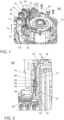
- Fig. 1 shows an exploded view of a stator 100 for an electrical machine with a coil 10.
- the coil 10 has a hairpin winding.
- a sensor holder 12 is shown in an axial direction 11 above the stator 100.
- the sensor holder 12 comprises a main part 13 and a holding element 14.
- the holding element 14 is arranged on the main part 13 essentially perpendicular to an expansion plane 15 of the main part 13.
- the holding element 14 includes a receiving space 16.
- a temperature sensor 17 is arranged in the receiving space 16.
- a temperature sensor cable 18 is led out of the holding element 14.
- the temperature sensor cable 18 runs in a cable duct 19 formed on the sensor holder 12.
- the cable duct 19 includes side walls 20, 21 and a base 22. Furthermore, the cable duct 19 has projections 23 with which the temperature sensor cable 18 guided in the cable duct 19 in the cable duct 19 is held and locked.
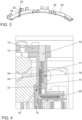
- Fig. 2 shows a cross-sectional section of a region of the stator 100 Fig. 1 .
- the holding element 14 includes a receiving space 16 in which the temperature sensor 17 and a heat-conducting element 24 are arranged.
- the heat-conducting element 24 is bent out of a busbar 25 and is essentially vertical, in particular in the Axial direction 11 of the stator 100 from the stator 100.
- the temperature sensor cable 18 is led out of the receiving space 16 of the holding element 14 and arranged in the cable duct 19 of the sensor holder 12.
- Temperature sensor 17 and heat-conducting element 24 have chamfers 28, 29 at the ends at tips 26, 27.
- the holding element 14 has an insertion opening 30 for introducing the heat-conducting element 24.
- the insertion opening 30 also has a chamfer 31.
- the heat-conducting element 24 with its tip 26 is introduced into the receiving space 16 through the insertion opening 30.
- the contact between the chamfer 28 at the tip 26 of the heat-conducting element 24 with the chamfer 31 of the insertion opening 30 and the chamfer 29 at the tip 27 of the temperature sensor 17 causes the heat-conducting element 24 to be inserted into the receiving space 16 parallel to the temperature sensor 17 and without blockages and that the temperature sensor 17 is not pushed out of the receiving space 16 of the holding element 14 in the axial direction 11.
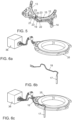
- Fig. 3 shows a busbar 25 with a heat-conducting element 24.
- the busbar 25 is designed to extend essentially in an extension plane 32 and has an approximately arcuate configuration in the extension plane 32.
- the busbar 25 includes a portion 33 that is bent out of the extension plane 32 and forms the heat-conducting element 24.
- the heat-conducting element 24 is designed in particular as a temperature lance 34 made of copper.
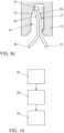
- Fig. 4 shows a further side view of the arrangement of temperature sensor 17 and heat-conducting element 24 in the holding element 14 of the sensor holder 12.
- the reference numbers correspond to those of Fig. 2 .
- a difference compared to the representation of the Fig. 2 is that the temperature sensor 17 and the heat-conducting element 24 have no end chamfers 28, 29.
- Fig. 5 shows a perspective view of the sensor holder 12.
- the sensor holder 12 has a main part 13 in an expansion plane 15.
- the holding element 14 projects approximately perpendicular to the main part 13 and the expansion plane 15.
- the cable duct 19 is clearly visible, comprising the base 22 and side walls 20, 21 for the temperature sensor cable 18.
- the side walls 20, 21 of the cable duct 19 have projections 23 with which the temperature sensor cable 18 is held in the cable duct 19.
- Fig. 6a to 6c show further possible elements of the stator 100.
- the stator 100 can designate an encoder module 35 for an angle encoder.
- the encoder module 35 and the temperature sensor cable 18 ( Fig. 6b ) are connected to a plug-in module 36, as in Fig. 6c shown.
- the temperature sensor 17 arranged at one end of the temperature sensor cable 18 is essentially flat and elongated.
- Fig. 7 shows the combination of sensor holder 12, temperature sensor 17 and encoder module 35 after assembly.
- encoder module 35, sensor holder 12 and temperature sensor 17 can be arranged as a unit on the stator.
- Fig. 8 corresponds to the arrangement Fig. 7 in an exploded view.
- a first hairpin 37 and a second hairpin 38 have end sections 39, 40 which protrude from the stator 100 in an axial direction 11. According to the state of the art Fig. 9a the end sections 39, 40 of the first hairpin 37 and the second hairpin 38 are welded together at a welding point 41.
- the first hairpin 37 has an extended end section 42 compared to the second hairpin 38.
- the first hairpin 37 and the second hairpin 38 are connected to one another in such a way that the extended end section 42 of the first hairpin 37 protrudes beyond the welding point 41 and over the end section 40 of the second hairpin 38 in the axial direction 11 of the stator 100.
- the extended end section 42 of the first hairpin 37 serves as a heat-conducting element 24.
- the holding element 14 of the sensor holder 12 has a receiving space 16 in which a flat temperature sensor 17 is arranged. The holding element 14 is placed with the temperature sensor 17 arranged therein in or against the axial direction 11 on the extended end section 42 of the first hairpin 37, which is designed as a heat-conducting element 24.
- Fig. 9c shows a further embodiment encompassed by the invention.
- the end sections 39, 40 of the first hairpin 37 and the second hairpin 38 are of the same length.
- the end sections 39, 40 can be extended, but it is also possible that the end sections 39, 40 of the first hairpin 37 and the second hairpin 38 are just as long as the end sections (not shown) of the other hairpins of the coil 10, which are not in thermal contact with the temperature sensor 17.
- the end sections 39, 40 of the first hairpin 37 and the second hairpin 38 are also welded together at a welding point 41.
- the hairpins 37, 38 are in the design of the Fig. 9c
- the hairpins 37, 38 are bent in their course, so that the end sections 39, 40 are angled at an obtuse angle.
- the end sections are angled or bent before the holding element 14 is attached and before or after the welding point 41 is produced.
- Both end sections 39, 40 are accommodated in the receiving space 16 of the holding element 14, with preferably only one end section 39 being in thermal contact with the temperature sensor 17. Because the end sections 39, 40 are angled, the welding point 41 does not come into contact with the temperature sensor 17 when the end sections 39, 40 are inserted into the receiving space 16 of the holding element 14 and cannot damage it.
- the upper region of the receiving space 16 has a chamfer 43.
- the hairpins 37, 38 By contacting the angled end sections 39, 40 with the chamfer 43, the hairpins 37, 38, in particular the first hairpin 37, are pressed against the temperature sensor 17.
- the advantage of this embodiment is that the current, in particular through the hairpins 37, 38, is conducted directly past the temperature sensor 17. Furthermore, no new welding process is necessary.
- the hairpins 37 and 38 can be connected or welded to one another like all other hairpins of the coil 10.
- a flowchart for a method for producing an electrical machine is shown.
- a stator 100 with a coil 10 with a coil winding or a hairpin winding is provided, the stator 100 having a heat-conducting element 24, the heat-conducting element 24 being arranged outside the coil 10 and/or protruding from the coil 10.
- a temperature sensor 17 is arranged in a receiving space 16 of a holding element 14 of a sensor holder 12.
- a third method step S3 the sensor holder 12 is arranged on the stator 100 in such a way that the heat-conducting element 24 is inserted into the receiving space 16 of the holding element 14, so that the temperature sensor 17 is in direct thermal contact with the heat-conducting element 24.
Description
Stator für eine elektrische Maschine und Verfahren zum Herstellen einer elektrischen Maschine Die vorliegende Erfindung betrifft einen Stator für eine elektrische Maschine mit einer Spule mit einer Spulenwicklung oder einer Hairpinwicklung und einem Temperatursensor, wobei der Stator ein Wärmeleitelement aufweist, wobei der Temperatursensor in direktem thermischen Kontakt mit dem Wärmeleitelement angeordnet ist. Ferner betrifft die vorliegende Erfindung eine elektrische Maschine und ein Verfahren zum Herstellen einer elektrischen Maschine.Stator for an electrical machine and method for producing an electrical machine The present invention relates to a stator for an electrical machine with a coil with a coil winding or a hairpin winding and a temperature sensor, the stator having a heat-conducting element, the temperature sensor being in direct thermal contact with the heat-conducting element is arranged. The present invention further relates to an electrical machine and a method for producing an electrical machine.
Elektrische Maschinen finden unter anderem Anwendung in Elektro- oder Hybridfahrzeugen. Darüber hinaus werden elektrische Maschinen auch in vielen weiteren Vorrichtungen und Industriezweigen verwendet.Electric machines are used, among other things, in electric or hybrid vehicles. In addition, electrical machines are also used in many other devices and industries.
Eine elektrische Maschine umfasst einen Rotor und einen Stator. Der Stator weist in der Regel eine Spule zur Erzeugung eines magnetischen Wechselfelds auf. Der Rotor ist mit Magneten ausgestattet und rotierbar gelagert, wobei eine Rotation des Rotors durch die Wechselwirkung des magnetischen Wechselfelds der Spule mit dem Magnetfeld der Magneten des Rotors erzeugt wird.An electric machine includes a rotor and a stator. The stator usually has a coil for generating an alternating magnetic field. The rotor is equipped with magnets and is rotatably mounted, with rotation of the rotor being generated by the interaction of the alternating magnetic field of the coil with the magnetic field of the rotor's magnets.
Insbesondere bei der Anwendung in Elektrofahrzeugen oder Hybridfahrzeugen werden hohe Anforderungen an die Leistung der elektrischen Maschine gestellt. Aufgrund der durch die Leistungsabgabe entstehenden Wärmeentwicklung muss die Temperatur der elektrischen Maschine, und insbesondere die der thermisch hoch belasteten Statorspule mittels Temperatursensoren überwacht werden.Particularly when used in electric vehicles or hybrid vehicles, high demands are placed on the performance of the electric machine. Due to the heat generated by the power output, the temperature of the electrical machine, and in particular that of the stator coil, which is subject to high thermal loads, must be monitored using temperature sensors.
Aus der
Aus der
Aus der
Die
Aus der
Die
Aus der
Die
Aus der
Bei anderen bekannten Konzepten wird ein Temperatursensor auf einen Wickelkopf der Spule des Stators bandagiert oder auf dem Wickelkopf angeclipst.In other known concepts, a temperature sensor is bandaged onto a winding head of the stator coil or clipped onto the winding head.
Aufgrund der aufwendigen, von einem Monteur vorzunehmenden Handgriffe zur Anordnung eines Temperatursensors an einem Stator sind die aus dem Stand der Technik bekannten Ansätze zur Bereitstellung eines Stators mit einem Temperatursensor nur schlecht automatisierbar.Due to the complex steps that a technician has to carry out to arrange a temperature sensor on a stator, the approaches known from the prior art for providing a stator with a temperature sensor are difficult to automate.
Ferner sind bei den bekannten Lösungen die Temperatursensoren fest mit dem Stator verbunden und müssen vor dem Imprägnieren am Stator angebracht werden. Die Handhabung der aus dem Stand der Technik bekannten Statoren wird zudem dadurch erschwert, dass während der Montage das Temperatursensorkabel gehalten werden muss.Furthermore, in the known solutions, the temperature sensors are firmly connected to the stator and must be attached to the stator before impregnation. Handling the stators known from the prior art is also made more difficult by the fact that the temperature sensor cable has to be held during assembly.
Der vorliegenden Erfindung liegt die Aufgabe zugrunde, einen Stator für eine elektrische Maschine mit einer Spule mit einer Spulenwicklung oder einer Hairpinwicklung und einem Temperatursensor bereitzustellen, dessen Montage einfach und leicht automatisierbar ist, welcher eine zuverlässige Temperaturmessung gestattet und kostengünstig herzustellen ist. Zur Lösung der Aufgabe wird ein Stator für eine elektrische Maschine mit einer Spule mit einer Spulenwicklung oder einer Hairpinwicklung und einem Temperatursensor, wobei der Stator ein Wärmeleitelement aufweist, wobei der Temperatursensor in direktem thermischen Kontakt mit dem Wärmeleitelement angeordnet ist, vorgeschlagen, wobei das Wärmeleitelement außerhalb der Spule angeordnet ist und/oder von der Spule absteht, wobei der Stator einen Stromleiter aufweist, wobei der Stromleiter eine Stromschiene ist, wobei das Wärmeleitelement aus dem Stromleiter herausgeformt ist, wobei das Wärmeleitelement ein Teilbereich des Stromleiters ist, wobei der Teilbereich aus einer Erstreckungsebene des Stromleiters herausgebogen ist, und wobei ein Sensorhalter vorgesehen ist, wobei der Sensorhalter ein Halteelement mit einem Aufnahmeraum aufweist, wobei der Temperatursensor und das Wärmeleitelement in dem Aufnahmeraum angeordnet sind, sodass der Temperatursensor in direktem thermischen Kontakt mit dem Wärmeleitelement steht.The present invention is based on the object of providing a stator for an electrical machine with a coil with a coil winding or a hairpin winding and a temperature sensor, the assembly of which is simple and easy to automate, which allows reliable temperature measurement and is inexpensive to produce. To solve the problem, a stator for an electrical machine with a coil with a coil winding or a hairpin winding and a temperature sensor, the stator having a heat-conducting element, the temperature sensor being arranged in direct thermal contact with the heat-conducting element, is proposed, with the heat-conducting element outside the coil is arranged and/or protrudes from the coil, the stator having a current conductor, the current conductor being a busbar, the heat-conducting element being formed out of the current conductor, the heat-conducting element being a portion of the current conductor, the portion consisting of an extension plane of the current conductor is bent out, and wherein a sensor holder is provided, wherein the sensor holder has a holding element with a receiving space, the temperature sensor and the heat-conducting element being arranged in the receiving space, so that the temperature sensor is in direct thermal contact with the heat-conducting element.
Die Spule kann eine herkömmliche Spulenwicklung oder eine Hairpinwicklung aufweisen.The coil can have a conventional coil winding or a hairpin winding.
Bei einer Hairpinwicklung werden sogenannte Hairpins an einem Spulenträger des Stators angeordnet. Die aus dem Stator hervorstehenden Enden der Hairpins werden miteinander verbunden, insbesondere verschweißt.In a hairpin winding, so-called hairpins are arranged on a coil carrier of the stator. The ends of the hairpins protruding from the stator are connected to one another, in particular welded.
Besonders vorteilhaft ist, dass das Wärmeleitelement, welches in direktem thermischen Kontakt mit dem Temperatursensor steht, außerhalb der Spule angeordnet ist und/oder von der Spule absteht.It is particularly advantageous that the heat-conducting element, which is in direct thermal contact with the temperature sensor, is arranged outside the coil and/or protrudes from the coil.
Durch die Anordnung des Wärmeleitelementes außerhalb der Spule oder durch das Abstehen des Wärmeleitelementes von der Spule ist eine Herstellung des thermischen Kontakts zwischen Wärmeleitelement und Temperatursensor ohne aufwendige Montageschritte durchführbar. Insbesondere muss der Temperatursensor nicht mehr zwischen die Windungen der Spule gesteckt werden. Hinzu kommt, dass der Temperatursensor durch Vorsehen eines außerhalb der Spule angeordneten oder von der Spule abstehenden Wärmeleitelements nicht vor dem Imprägnieren des Stators angebracht und nicht fest mit dem Stator verbunden werden muss. Das außerhalb der Spule angeordnete und/oder von der Spule abstehende Wärmeleitelement bietet eine einfache, zur Kontaktierung mit einem Temperatursensor ausgebildete Wärmeschnittstelle, über die eine zuverlässige Temperaturmessung ermöglicht wird. Insbesondere bei aus dem Stand der Technik bekannten, an einem Wickelkopf angeclipsten oder aufbandagierten Temperatursensoren lässt sich eine derartig einfache Kontaktierung und zuverlässige Temperaturmessung nicht erzielen.By arranging the heat-conducting element outside the coil or by protruding the heat-conducting element from the coil, thermal contact can be established between the heat-conducting element and the temperature sensor without complex assembly steps. In particular, the temperature sensor no longer needs to be inserted between the turns of the coil. In addition, by providing a heat-conducting element arranged outside the coil or protruding from the coil, the temperature sensor does not have to be attached before the stator is impregnated and does not have to be firmly connected to the stator. The heat-conducting element arranged outside the coil and/or protruding from the coil offers a simple thermal interface designed for contacting a temperature sensor, via which a reliable temperature measurement is made possible. In particular, with temperature sensors known from the prior art that are clipped or bandaged onto a winding head, such simple contacting and reliable temperature measurement cannot be achieved.
Bevorzugt ist der Temperatursensor ausgebildet, über den direkten thermischen Kontakt mit dem Wärmeleitelement eine Temperatur der Spule und/oder eines Stromleiters zu ermitteln.The temperature sensor is preferably designed to determine a temperature of the coil and/or a current conductor via direct thermal contact with the heat-conducting element.
Bevorzugt kann vorgesehen sein, dass das Wärmeleitelement stiftförmig und/oder drahtförmig und/oder stabförmig ist.It can preferably be provided that the heat-conducting element is pin-shaped and/or wire-shaped and/or rod-shaped.
Durch eine stiftförmige, drahtförmige oder stabförmige Ausgestaltung des Wärmeleitelementes wird der Ort der Temperaturmessung präzise lokalisiert, wodurch eine zuverlässige Temperaturmessung ermöglicht wird. Ein weiterer Vorteil eines stiftförmigen, drahtförmigen oder stabförmigen Wärmeleitelementes besteht darin, dass die thermische Kontaktierung mit einem Temperatursensor vereinfacht wird.Through a pin-shaped, wire-shaped or rod-shaped design of the heat-conducting element, the location of the temperature measurement is precisely localized, which enables a reliable temperature measurement. Another advantage of a pin-shaped, wire-shaped or rod-shaped heat-conducting element is that thermal contacting with a temperature sensor is simplified.
Weiter kann mit Vorteil vorgesehen sein, dass das Wärmeleitelement eine Temperaturlanze, insbesondere eine Temperaturlanze aus Kupfer, ist.Furthermore, it can advantageously be provided that the heat-conducting element is a temperature lance, in particular a temperature lance made of copper.
Eine außerhalb der Spule angeordnete oder von der Spule abstehende Temperaturlanze ermöglicht eine präzise und zuverlässige Temperaturmessung. Aufgrund der Ausgestaltung des Wärmeleitelementes als Temperaturlanze und deren Anordnung außerhalb der Spule oder abstehend von der Spule wird eine einfache Kontaktierung mit dem Temperatursensor ermöglicht. Unter einer Kontaktierung kann ein direkter Kontakt verstanden werden. Ein indirekter thermischer Kontakt ist eine nicht erfindungsgemäße Option, und kann als eine berührungsfreie relative Anordnung von Temperatursensor und Wärmeleitelement ausgebildet sein, derart, dass thermische Energie über Konvektion eines Mediums wie Luft oder elektromagnetische Strahlung von dem Wärmeleitelement an den Temperatursensor übertragen wird.A temperature lance arranged outside the coil or protruding from the coil enables precise and reliable temperature measurement. Due to the design of the heat-conducting element as a temperature lance and its arrangement outside the coil or protruding from the coil, easy contact with the temperature sensor is made possible. Contact can be understood as direct contact. An indirect thermal contact is an option not according to the invention and can be designed as a contact-free relative arrangement of the temperature sensor and the heat-conducting element, such that thermal energy is transferred from the heat-conducting element to the temperature sensor via convection of a medium such as air or electromagnetic radiation.
Eine Temperaturlanze aus Kupfer ist besonders für eine effektive Wärmeleitung und Wärmeübertragung geeignet.A copper temperature lance is particularly suitable for effective heat conduction and heat transfer.
Bevorzugt ist vorgesehen, dass der Stator ein Hairpin-Stator ist. In einer nicht von der Erfindung umfassten Ausführungsform kann das Wärmeleitelement als ein verlängerter Endabschnitt eines ersten Hairpins ausgebildet sein,It is preferably provided that the stator is a hairpin stator. In an embodiment not covered by the invention, the heat-conducting element can be designed as an extended end section of a first hairpin,
Bei einem Hairpinstator werden sogenannte Hairpins in den Wicklungsträger des Stators eingeführt. Endseitig, in einer Axialrichtung des Stators, ragen die Hairpins aus dem Stator hervor. Die aus dem Stator hervorragenden Endabschnitte von mindestens einem ersten Hairpin und einem zweiten Hairpin werden durch Verschweißen an einem Schweißpunkt miteinander verbunden. Die an ihren Endabschnitten miteinander verbundenen oder verschweißten Hairpins bilden den Spulen- oder Wickelkopf der Spule aus.In a hairpin stator, so-called hairpins are inserted into the winding carrier of the stator. At the end, in an axial direction of the stator, the hairpins protrude from the stator. The end sections of at least a first hairpin and a second hairpin protruding from the stator are connected to one another by welding at a welding point. The hairpins, which are connected or welded to one another at their end sections, form the coil or winding head of the coil.
Bevorzugt kann vorgesehen sein, dass ein erster der Hairpins einen verlängerten Endabschnitt aufweist, welcher über den Spulenkopf oder den Wickelkopf hinausragt. Die Verbindung zwischen dem ersten Hairpin und dem zweiten Hairpin wird dann in einer Weise hergestellt, dass der verlängerte Endabschnitt des ersten Hairpins in einer axialen Richtung des Stators über den Schweißpunkt und den Endabschnitt des zweiten Hairpins hinausragt. Der verlängerte Endabschnitt des ersten Hairpins ist dann bevorzugt als freistehender Endabschnitt ausgebildet. Der aus der Spule, insbesondere dem Spulenkopf der Spule, hervorstehende verlängerte Endabschnitt des ersten Hairpins kann dann als Wärmeleitelement ausgebildet sein, mit dem der Temperatursensor thermisch kontaktiert wird. Da der verlängerte Endabschnitt aus der Spule oder dem Spulenkopf herausragt oder von diesem hervorsteht, kann der Temperatursensor einfach und insbesondere nach dem Imprägnieren des Stators mit dem Wärmeleitelement thermisch kontaktiert werden. Zudem ist die Montage leicht automatisierbar.It can preferably be provided that a first of the hairpins has an extended end section which projects beyond the coil head or the winding head. The connection between the first hairpin and the second hairpin is then established in such a way that the extended end portion of the first hairpin protrudes in an axial direction of the stator beyond the welding point and the end portion of the second hairpin. The extended end section of the first hairpin is then preferably designed as a free-standing end section. The extended end section of the first hairpin protruding from the coil, in particular the coil head of the coil, can then be designed as a heat-conducting element with which the temperature sensor is thermally contacted. Since the extended end portion protrudes or protrudes from the coil or coil head, The temperature sensor can be thermally contacted with the heat-conducting element easily and in particular after the stator has been impregnated. In addition, assembly can be easily automated.
Bevorzugt ist vorgesehen, dass das Wärmeleitelement aus der Spule, insbesondere aus einem Spulenkopf der Spule, hervorsteht.It is preferably provided that the heat-conducting element protrudes from the coil, in particular from a coil head of the coil.
Erfindungsgemäß ist vorgesehen, dass der Stator einen Stromleiter aufweist und dass das Wärmeleitelement aus dem Stromleiter herausgeformt ist. So kann die Strom- bzw.According to the invention it is provided that the stator has a current conductor and that the heat-conducting element is formed from the current conductor. In this way, the electricity or
Leistungsversorgung der Spule des Stators durch eine Sternschaltung oder eine Dreiecksschaltung realisiert sein. Vorteilhaft an der Herausformung des Wärmeelementes aus dem Stromleiter ist, dass die Stromleiter der Sternschaltung oder der Dreiecksschaltung als sogenannte "Hotspots" aufgrund der hohen Stromdichte eine sehr hohe Temperatur aufweisen können. Durch die Messung der Temperatur über ein aus einem Stromleiter herausgeformtes Wärmeleitelement können derartige Hotspots präzise und zuverlässig überwacht werden. Ein weiterer Vorteil der Herausformung des Wärmeleitelementes aus dem Stromleiter besteht darin, dass die Spule des Stators einer elektrischen Maschine imprägniert werden kann, bevor der Temperatursensor angebracht wird.Power supply to the coil of the stator can be realized by a star connection or a delta connection. The advantage of forming the heat element out of the current conductor is that the current conductors of the star connection or the delta connection can have a very high temperature as so-called "hotspots" due to the high current density. By measuring the temperature via a heat-conducting element formed from a power conductor, such hotspots can be monitored precisely and reliably. A further advantage of forming the heat-conducting element out of the current conductor is that the coil of the stator of an electrical machine can be impregnated before the temperature sensor is attached.
Es kann vorgesehen sein, dass der verlängerte Endabschnitt des ersten Hairpins über einen Verbindungspunkt, insbesondere über einen Schweißpunkt, des ersten Hairpins mit einem zweiten Hairpin hinaussteht.It can be provided that the extended end section of the first hairpin protrudes beyond a connection point, in particular beyond a welding point, of the first hairpin with a second hairpin.
Insbesondere wenn der verlängerte Endabschnitt des ersten Hairpins über den Verbindungspunkt in einer Axialrichtung des Stators und somit über den Spulen- oder Wickelkopf der Spule des Stators hinausragt, kann eine einfache und sichere thermische Kontaktierung von Temperatursensor und Wärmeleitelement hergestellt werden. Erfindungsgemäß ist vorgesehen, dass der Stromleiter eine Stromschiene ist, wobei die Stromschiene eine Sternschiene oder ein Neutralleiter einer Sternschaltung ist.In particular, if the extended end section of the first hairpin protrudes beyond the connection point in an axial direction of the stator and thus beyond the coil or winding head of the coil of the stator, a simple and secure thermal contact between the temperature sensor and the heat-conducting element can be established. According to the invention it is provided that the current conductor is a busbar, wherein the busbar is a star rail or a neutral conductor of a star connection.
Aufgrund der hohen Stromdichte stellt insbesondere die Sternschiene oder der Neutralleiter einer Sternschaltung einen Hotspot dar. Erfindungsgemäß ist das Wärmeleitelement aus einer Sternschiene oder einem Neutralleiter einer Sternschaltung herausgeformt.Due to the high current density, the star rail or the neutral conductor of a star connection in particular represents a hotspot. This is according to the invention Heat-conducting element formed from a star rail or a neutral conductor of a star circuit.
Erfindungsgemäß ist ferner vorgesehen, dass das Wärmeleitelement ein Teilbereich des Stromleiters, insbesondere der Stromschiene, ist, wobei der Teilbereich aus einer Erstreckungsebene des Stromleiters, insbesondere der Stromschiene, herausgebogen ist. Bevorzugt steht das Wärmeleitelement in einem Winkel zu der Erstreckungsebene des Stromleiters, insbesondere der Stromschiene.According to the invention it is further provided that the heat-conducting element is a partial region of the current conductor, in particular the busbar, wherein the partial region is bent out of an extension plane of the current conductor, in particular the busbar. The heat-conducting element is preferably at an angle to the plane of extension of the current conductor, in particular the busbar.
Die Stromschiene kann dabei im Wesentlichen eben ausgebildet sein und sich in einer Erstreckungsebene erstrecken. Innerhalb der Erstreckungsebene kann die Stromschiene zudem im Wesentlichen bogenförmig ausgeführt sein. Die Bogenform kann dabei einem vollen Kreis oder auch nur einem Teilausschnitt eines Kreises entsprechen.The busbar can be essentially flat and extend in an extension plane. Within the extension plane, the busbar can also be designed to be essentially arcuate. The arc shape can correspond to a full circle or just a partial section of a circle.
Die Stromschiene weist mindestens einen Teilbereich, wie einen Fortsatz oder einen Vorsprung oder ähnliches, auf. Der Teilbereich, der Fortsatz oder der Vorsprung, ist oder wird aus der Erstreckungsebene herausgebogen und bildet das Wärmeleitelement. Besonders bevorzugt steht das derart ausgebildete Wärmeleitelement in einem Winkel zu der Erstreckungsebene des Stromleiters, insbesondere der Stromschiene. Da die Stromschiene im zusammengebauten Zustand des Stators, beziehungsweise der elektrischen Maschine, im Wesentlichen in einer Ebene senkrecht zu der Axialrichtung des Stators angeordnet werden kann, wird durch Herausbiegen des Teilbereiches des Stromleiters, beziehungsweise der Stromschiene, das so gebildete Wärmeleitelement in Richtung der Axialrichtung des Stators gebogen. Hierdurch vereinfacht sich eine Montage und thermische Kontaktierung des Temperatursensors an dem Wärmeleitelement in der Axialrichtung des Stators.The busbar has at least one partial area, such as an extension or a projection or the like. The partial area, the extension or the projection, is or is bent out of the extension plane and forms the heat-conducting element. Particularly preferably, the heat-conducting element designed in this way is at an angle to the plane of extension of the current conductor, in particular the busbar. Since the busbar in the assembled state of the stator or the electrical machine can be arranged essentially in a plane perpendicular to the axial direction of the stator, by bending out the partial area of the current conductor or the busbar, the heat-conducting element thus formed is moved in the direction of the axial direction of the Stator bent. This simplifies assembly and thermal contacting of the temperature sensor on the heat-conducting element in the axial direction of the stator.
Der Winkel zwischen Wärmeleitelement und Stromleiter beziehungsweise Stromschiene kann zwischen 45° und 90°, bevorzugt zwischen 80° und 90°, besonders bevorzugt zwischen 85° und 90°, ganz besonders bevorzugt 90°, betragen.The angle between the heat-conducting element and the current conductor or busbar can be between 45° and 90°, preferably between 80° and 90°, particularly preferably between 85° and 90°, very particularly preferably 90°.
Mit weiterem Vorteil kann vorgesehen sein, dass das Wärmeleitelement von dem Stator und/oder dem Spulenkopf in einer Radialrichtung des Stators oder in einer Axialrichtung des Stators absteht.With further advantage it can be provided that the heat-conducting element projects from the stator and/or the coil head in a radial direction of the stator or in an axial direction of the stator.
Wenn das Wärmeleitelement in einer Axialrichtung des Stators absteht, wird eine Montage besonders vereinfacht. Insbesondere wird die Montage des Temperatursensors an dem Stator beziehungsweise an dem Wärmeleitelement vereinfacht, da die Fügerichtung oder Montagerichtung des Temperatursensors in diesem Fall der Montagerichtung des Resolvers oder Winkelgebers des Stators entsprechen kann.If the heat-conducting element projects in an axial direction of the stator, assembly is particularly simplified. In particular, the assembly of the temperature sensor on the stator or on the heat-conducting element is simplified, since the joining direction or assembly direction of the temperature sensor in this case can correspond to the assembly direction of the resolver or angle encoder of the stator.
Mit weiterem Vorteil kann vorgesehen sein, dass das Wärmeleitelement und/oder der Temperatursensor endseitig eine Fase aufweist.With further advantage it can be provided that the heat-conducting element and/or the temperature sensor has a chamfer at the end.
Das Vorsehen einer Fase an dem Wärmeleitelement und/oder an dem Temperatursensor ist insbesondere dann vorteilhaft, wenn Temperatursensor und Wärmeleitmittel beim Anordnen des Temperatursensors an dem Wärmeleitmittel in physischen Kontakt miteinander kommen. Durch das Vorsehen einer Fase, auch Einführschräge genannt, endseitig, insbesondere an einer Spitze, des Wärmeleitmittels und/oder des Temperatursensors wird das aneinander Anordnen dieser beiden Elemente vereinfacht. Insbesondere kommt es zu keinen gegenseitigen Blockaden, und der Temperatursensor und das Wärmeleitelement können aneinander gleitend vorbeigeführt werden.Providing a chamfer on the heat-conducting element and/or on the temperature sensor is particularly advantageous if the temperature sensor and heat-conducting means come into physical contact with one another when arranging the temperature sensor on the heat-conducting means. By providing a chamfer, also called an insertion bevel, at the end, in particular at a tip, of the heat-conducting means and/or the temperature sensor, arranging these two elements together is simplified. In particular, there are no mutual blockages, and the temperature sensor and the heat-conducting element can be guided past each other in a sliding manner.
Wenn der Temperatursensor in einem Halteelement angeordnet ist, in welches das Wärmeleitelement beim Anordnen des Temperatursensors an den Stator ebenfalls eingeführt wird, ist das Vorsehen einer Fase an dem Wärmeleitmittel und/oder an dem Temperatursensor vorteilhaft. Beim Stecken des Wärmeleitmittels in das Haltelement wird der Temperatursensor nicht beschädigt, und der Temperatursensor wird zudem nicht aus dem Halteelement herausgedrückt.If the temperature sensor is arranged in a holding element into which the heat-conducting element is also inserted when arranging the temperature sensor on the stator, providing a chamfer on the heat-conducting means and/or on the temperature sensor is advantageous. When the heat-conducting medium is inserted into the holding element, the temperature sensor is not damaged, and the temperature sensor is also not pushed out of the holding element.
Gemäß der Erfindung ist zudem ein Sensorhalter vorgesehen, wobei der Sensorhalter ein Halteelement mit einem Aufnahmeraum aufweist, wobei der Temperatursensor und das Wärmeleitmittel in dem Aufnahmeraum angeordnet sind, sodass der Temperatursensor in direktem thermischen Kontakt mit dem Wärmeleitelement steht.According to the invention, a sensor holder is also provided, wherein the sensor holder has a holding element with a receiving space, the temperature sensor and the heat-conducting means being arranged in the receiving space, so that the temperature sensor is in direct thermal contact with the heat-conducting element.
Die Anordbarkeit oder die Anordnung von Temperatursensor und Wärmeleitelement in einem Aufnahmeraum eines dafür vorgesehenen Halteelements ermöglicht eine präzise relative Positionierung des Wärmeleitelements an dem Temperatursensor. Hierdurch wird eine zuverlässige Temperaturmessung ermöglicht.The arrangability or arrangement of the temperature sensor and heat-conducting element in a receiving space of a holding element provided for this purpose enables precise relative positioning of the heat-conducting element on the temperature sensor. This enables reliable temperature measurement.
Ein weiterer Vorteil des Vorsehens eines Halteelementes mit einem Aufnahmeraum besteht darin, dass die Montage des Temperatursensors weiter vereinfacht wird.A further advantage of providing a holding element with a receiving space is that the assembly of the temperature sensor is further simplified.
Mit weiterem Vorteil ist vorgesehen, dass der Sensorhalter einen Hauptteil aufweist, wobei der Hauptteil sich im Wesentlichen in einer Ausdehnungsebene erstreckt, wobei der Hauptteil in der Ausdehnungsebene bevorzugt eine im Wesentlichen bogenförmige Ausgestaltung aufweist.It is further advantageously provided that the sensor holder has a main part, the main part extending essentially in a plane of expansion, the main part preferably having a substantially arcuate configuration in the plane of expansion.
Durch die Ausbildung des Sensorhalters in einer Ausdehnungsebene kann dieser mit besonderem Vorteil auf einer axialen Stirnfläche des Stators angeordnet werden. Insbesondere kann der Sensorhalter parallel zu einer in einer Erstreckungsebene ausgerichteten und am Stator befestigten Stromschiene angeordnet werden.By designing the sensor holder in an expansion plane, it can be arranged with particular advantage on an axial end face of the stator. In particular, the sensor holder can be arranged parallel to a busbar aligned in an extension plane and attached to the stator.
Der bevorzugte Sensorhalter wird bei der Montage derart an einer axialen Stirnseite des Stators angeordnet, dass die Ausdehnungsebene im Wesentlichen senkrecht zur Axialrichtung des Stators ausgebildet ist. Insbesondere wird der Sensorhalter bevorzugt im Bereich des Wickelkopfes oder des Spulenkopfes auf einem den Stator umlaufenden Rand aufgesetzt. Zwischen dem Rand des Stators und dem Sensorhalter kann zudem ein Geberelement, beispielsweise für einen Drehwinkelsensor, angeordnet sein.During assembly, the preferred sensor holder is arranged on an axial end face of the stator in such a way that the plane of expansion is formed essentially perpendicular to the axial direction of the stator. In particular, the sensor holder is preferably placed in the area of the winding head or the coil head on an edge surrounding the stator. A transmitter element, for example for a rotation angle sensor, can also be arranged between the edge of the stator and the sensor holder.
Bevorzugt kann vorgesehen sein, dass das Halteelement im Wesentlichen senkrecht zu der Ausdehnungsebene an dem Hauptteil des Sensorhalters angeformt oder angeordnet ist.It can preferably be provided that the holding element is formed or arranged on the main part of the sensor holder essentially perpendicular to the plane of expansion.
Durch die senkrechte Anordnung des Halteelementes an dem Hauptteil kann der Sensorhalter, bevorzugt mit eingesetztem Temperatursensor, entlang der Axialrichtung des Stators und/oder in der Fügerichtung des Resolvers auf den Rand des Stators aufgesetzt werden. Mit dieser Maßnahme kann gleichzeitig das, in einem rechten Winkel von dem Hauptteil abstehende, Halteelement auf das in Axialrichtung aus dem Stator oder der Spule hervorstehende oder außerhalb der Spule angeordnete Wärmeleitelement aufgesteckt werden.Due to the vertical arrangement of the holding element on the main part, the sensor holder, preferably with the temperature sensor inserted, can be placed on the edge of the stator along the axial direction of the stator and/or in the joining direction of the resolver. With this measure, the holding element, which protrudes at a right angle from the main part, can be plugged onto the heat-conducting element which protrudes in the axial direction from the stator or the coil or is arranged outside the coil.
Der Temperatursensor und das Wärmeleitelement sind im montierten Zustand in dem Halteelement angeordnet und zusammen mit dem Halteelement im Wesentlichen senkrecht zu der Ausdehnungsebene des Sensorhalters und/oder zu der Erstreckungsebene der Stromschiene ausgerichtet oder angeordnet.The temperature sensor and the heat-conducting element are in the assembled state arranged on the holding element and aligned or arranged together with the holding element substantially perpendicular to the plane of extension of the sensor holder and/or to the plane of extension of the busbar.
Bevorzugt kann ferner vorgesehen sein, dass das Halteelement eine Einführöffnung zum Einführen des Wärmeleitelementes aufweist, wobei der Aufnahmeraum derart ausgebildet ist, dass das Wärmeleitelement beim Einführen des Wärmeleitelementes in den Aufnahmeraum durch die Einführöffnung parallel zum Temperatursensor geführt wird und neben dem Temperatursensor anordbar oder angeordnet ist.Preferably, it can further be provided that the holding element has an insertion opening for inserting the heat-conducting element, the receiving space being designed such that the heat-conducting element is guided through the insertion opening parallel to the temperature sensor when the heat-conducting element is inserted into the receiving space and can be arranged or arranged next to the temperature sensor .
Das Vorsehen einer Einführöffnung erleichtert das Einführen des Wärmeleitelementes in das Halteelement, sodass die Montage des Stators vereinfacht wird.Providing an insertion opening makes it easier to insert the heat-conducting element into the holding element, so that the assembly of the stator is simplified.
Ferner wird durch die parallele Führung des Wärmeleitelementes zum Temperatursensor und die sich daraus ergebende parallele Anordnung des Wärmeleitelementes mit dem Temperatursensor ein wohldefinierter Überlappungsbereich von Wärmeleitelement und Temperatursensor bereitgestellt. Hierdurch kann die Wärmeübertragung von dem Wärmeleitelement auf den Temperatursensor und somit auch die Temperaturmessung optimiert werden.Furthermore, the parallel guidance of the heat-conducting element to the temperature sensor and the resulting parallel arrangement of the heat-conducting element with the temperature sensor provide a well-defined overlap area of the heat-conducting element and temperature sensor. This allows the heat transfer from the heat-conducting element to the temperature sensor and thus also the temperature measurement to be optimized.
Besonders bevorzugt ist der Temperatursensor und/oder das Wärmeleitelement an zumindest einer Seite flach oder eben ausgebildet.Particularly preferably, the temperature sensor and/or the heat-conducting element is flat or flat on at least one side.
Durch die flache oder ebene Ausgestaltung mindestens einer Seite des Temperatursensor und/oder des Wärmeleitelements kann der direkte thermische Kontakt zwischen Wärmleitelement und Temperatursensor optimiert werden, sodass die Temperaturmessung verbessert wird.Due to the flat or flat design of at least one side of the temperature sensor and/or the heat-conducting element, the direct thermal contact between the heat-conducting element and the temperature sensor can be optimized, so that the temperature measurement is improved.
Ferner kann vorgesehen sein, dass die Einführöffnung eine Fase aufweist, wobei bevorzugt die Fase ausgebildet ist, das Wärmeleitelement beim Einführen des Wärmeleitelementes in die Einführöffnung zu führen.Furthermore, it can be provided that the insertion opening has a chamfer, wherein the chamfer is preferably designed to guide the heat-conducting element into the insertion opening when the heat-conducting element is inserted.
In besonders vorteilhafter Weise kommt es somit beim Einführen des Wärmeleitelementes in das Halteelement zu einer Wechselwirkung zwischen der Fase der Einführöffnung und dem Wärmeleitelement, insbesondere der gegebenenfalls vorhandenen Fase des Wärmeleitelementes, sodass das Wärmeleitelement weitestgehend fehlerunanfällig und automatisiert in die Einführöffnung und somit in den Aufnahmeraum des Halteelementes eingeführt werden kann. Die Fase stellt dabei eine Einführschräge für das Wärmeleitelement dar, entlang welcher das Wärmeleitelement, insbesondere die Spitze des Wärmeleitelements, gleitend in die Einführungsöffnung geführt wird. Insbesondere wird das Wärmeleitelement beim Einführen des Wärmeleitelements durch die Einführöffnung des Halteelementes in den Aufnahmeraum des Halteelementes eingeleitet und kommt parallel zu dem Temperatursensor zu liegen.In a particularly advantageous manner, when the heat-conducting element is inserted into the holding element, there is an interaction between the chamfer of the insertion opening and the Heat-conducting element, in particular the chamfer of the heat-conducting element, if present, so that the heat-conducting element can be inserted into the insertion opening and thus into the receiving space of the holding element in a largely error-free and automated manner. The chamfer represents an insertion bevel for the heat-conducting element, along which the heat-conducting element, in particular the tip of the heat-conducting element, is slidably guided into the insertion opening. In particular, when the heat-conducting element is inserted, the heat-conducting element is introduced into the receiving space of the holding element through the insertion opening of the holding element and comes to lie parallel to the temperature sensor.
Mit weiterem Vorteil kann vorgesehen sein, dass der Sensorhalter, insbesondere der Hauptteil des Sensorhalters, einen Kabelkanal aufweist, wobei der Kabelkanal einen Boden und Seitenwände umfasst, wobei ein Temperatursensorkabel in dem Kabelkanal anordbar oder angeordnet ist.With further advantage it can be provided that the sensor holder, in particular the main part of the sensor holder, has a cable duct, the cable duct comprising a base and side walls, wherein a temperature sensor cable can be arranged or is arranged in the cable duct.
Aus dieser Maßnahme ergibt sich der Vorteil, dass das Temperatursensorkabel während der Montage des Temperatursensor beziehungsweise des Sensorhalters am Stator nicht von einem Monteur gehalten werden muss. Die Montage des Stators kann daher weiter vereinfacht und automatisiert werden.This measure has the advantage that the temperature sensor cable does not have to be held by a technician during assembly of the temperature sensor or the sensor holder on the stator. The assembly of the stator can therefore be further simplified and automated.
Mit weiterem Vorteil kann vorgesehen sein, dass die Seitenwände des Kabelkanals Vorsprünge aufweisen, sodass das in dem Kabelkanal angeordnete Temperatursensorkabel von den Vorsprüngen in den Kabelkanal gehalten oder arretiert wird.With further advantage it can be provided that the side walls of the cable duct have projections, so that the temperature sensor cable arranged in the cable duct is held or locked in the cable duct by the projections.
Die Vorsprünge können dabei als Rastnasen, Haken oder Zapfen ausgebildet sein. Insbesondere kann das Temperatursensorkabel vor der Montage des Stators in den Kabelkanal eingesetzt und bevorzugt durch Druck derart eingeclipst werden, dass das Temperatursensorkabel von den Vorsprüngen in dem Kabelkanal gehalten oder arretiert wird. Der Sensorhalter kann in Einheit mit dem Temperatursensor leichter gehandhabt werden und ohne Probleme an dem Stator befestigt werden.The projections can be designed as locking lugs, hooks or pins. In particular, the temperature sensor cable can be inserted into the cable duct before mounting the stator and preferably clipped in by pressure in such a way that the temperature sensor cable is held or locked by the projections in the cable duct. The sensor holder can be handled more easily in conjunction with the temperature sensor and can be attached to the stator without any problems.
Eine weitere Lösung der der Erfindung zugrundeliegenden Aufgabe besteht in der Bereitstellung eines Sensorhalters für einen Temperatursensor für einen vorbeschriebenen Stator.A further solution to the problem on which the invention is based is to provide a sensor holder for a temperature sensor for a stator described above.
Eine noch weitere Lösung für die der Erfindung zugrundeliegenden Aufgabe besteht in der Bereitstellung einer elektrischen Maschine mit einem vorbeschriebenen Stator.A yet further solution to the problem on which the invention is based is to provide an electrical machine with a stator as described above.
Zudem wird eine Lösung für die der Erfindung zugrundeliegenden Aufgabe durch die Bereitstellung eines Verfahrens zum Herstellen einer vorbeschriebenen elektrischen Maschine bereitgestellt, umfassend die Schritte:
- Bereitstellen eines Stators mit einer Spule mit einer Spulenwicklung oder einer Hairpinwicklung, wobei der Stator ein Wärmeleitelement aufweist, wobei das Wärmeleitelement außerhalb der Spule angeordnet ist und/oder von der Spule absteht, wobei der Stator einen Stromleiter aufweist, wobei der Stromleiter eine Stromschiene ist, und wobei das Wärmeleitelement aus dem Stromleiter herausgeformt wird, wobei das Wärmeleitelement ein Teilbereich des Stromleiters ist, wobei der Teilbereich aus einer Erstreckungsebene des Stromleiters herausgebogen ist,
- Anordnen eines Temperatursensors in einem Aufnahmeraum eines Halteelementes eines Sensorhalters,
- Anordnen des Sensorhalters an dem Stator derart, dass das Wärmeleitelement in den Aufnahmeraum des Halteelementes eingeführt wird, sodass der Temperatursensor in direktem thermischen Kontakt mit dem Wärmeleitelement steht.
- Providing a stator with a coil with a coil winding or a hairpin winding, the stator having a heat-conducting element, the heat-conducting element being arranged outside the coil and/or protruding from the coil, the stator having a current conductor, the current conductor being a busbar, and wherein the heat-conducting element is formed out of the current conductor, the heat-conducting element being a partial region of the current conductor, the partial region being bent out of an extension plane of the current conductor,
- Arranging a temperature sensor in a receiving space of a holding element of a sensor holder,
- Arranging the sensor holder on the stator in such a way that the heat-conducting element is inserted into the receiving space of the holding element, so that the temperature sensor is in direct thermal contact with the heat-conducting element.
Mit dem erfindungsgemäßen Verfahren werden die Vorteile des vorbeschriebenen Stators und/oder der vorbeschriebenen elektrischen Maschine erhalten. Insbesondere ergibt sich eine vereinfachte und automatisierte Montage des Stators bzw. der elektrischen Maschine. Die für den vorbeschriebenen Stator offenbarten Merkmale sind in sinngemäßer Weise auf das Verfahren übertragbar.With the method according to the invention, the advantages of the above-described stator and/or the above-described electrical machine are obtained. In particular, this results in a simplified and automated assembly of the stator or the electrical machine. The features disclosed for the stator described above can be transferred to the method in a corresponding manner.
Bevorzugt umfasst der Schritt des Bereitstellens eines Stators den Schritt des:
- Ausbildens des Wärmeleitelementes aus einem verlängerten Endabschnitt eines ersten Hairpins und/oder Ausbildens des Wärmeleitelementes durch Herausbiegen eines Teilbereichs eines Stromleiters, insbesondere einer Stromschiene, aus einer Erstreckungsebene des Stromleiters.
- Forming the heat-conducting element from an extended end section of a first hairpin and/or forming the heat-conducting element by bending out a portion of a current conductor, in particular a busbar, from an extension plane of the current conductor.
Ein Stromleiter beispielsweise einer Stern- oder Dreieckschaltung des Stators, insbesondere der Neutralleiter oder der Sternleiter einer Sternschaltung des Stators, stellt aufgrund der hohen in dem Stromleiter auftretenden Stromdichte einen sogenannten "Hotspot" mit einer sehr hohen Temperaturentwicklung dar.A current conductor, for example of a star or delta connection of the stator, in particular the neutral conductor or the star conductor of a star connection of the stator, represents a so-called "hotspot" with a very high temperature development due to the high current density occurring in the current conductor.
Die Ausbildung des Wärmeleitelementes aus einem Teilbereich des Stromleiters, insbesondere der Stromschiene, ermöglicht somit eine Messung und Überwachung der Temperaturen in einem kritischen Bereich des Stators.The formation of the heat-conducting element from a portion of the current conductor, in particular the busbar, thus enables the temperatures in a critical area of the stator to be measured and monitored.
Weiter bevorzugt kann vorgesehen sein, dass das Wärmeleitelement in einer Axialrichtung von dem Stator absteht und dass der Sensorhalter zur Anordnung an dem Stator entlang der Axialrichtung an den Stator herangeführt wird.Further preferably, it can be provided that the heat-conducting element projects from the stator in an axial direction and that the sensor holder is brought up to the stator along the axial direction for arrangement on the stator.
Somit entspricht die Montagerichtung des Sensorhalters der Montagerichtung eines Resolvers oder Winkelgebers des Stators. Durch diese gegenseitige Entsprechung der Montagerichtungen wird eine Automatisierung der Herstellung eines Stators bzw. einer elektrischen Maschine bevorteilt.The mounting direction of the sensor holder therefore corresponds to the mounting direction of a resolver or angle encoder of the stator. This mutual correspondence of the assembly directions favors automation of the production of a stator or an electrical machine.
Die Erfindung wird nachstehend anhand der Figuren näher erläutert:The invention is explained in more detail below with reference to the figures:
Es zeigen
- Fig. 1
- eine perspektivische Ansicht eines Stators einer elektrischen Maschine mit einem Sensorhalter,
- Fig. 2
- eine Querschnittsansicht eines Stators einer elektrischen Maschine mit einem Sensorhalter,
- Fig. 3
- eine Stromschiene eines Stators,
- Fig. 4
- eine weitere Querschnittsansicht eines Stators einer elektrischen Maschine mit einem Sensorhalter,
- Fig. 5
- einen Sensorhalter mit Halteelement und Kabelkanal,
- Fig. 6a
- ein Gebermodul eines Winkelgebers für eine elektrische Maschine,
- Fig. 6b
- einen Temperatursensor mit einem Temperatursensorkabel,
- Fig. 6c
- ein Gebermodul mit einem Steckmodul,
- Fig. 7
- einen Zusammenbau von Sensorhalter, Temperatursensor, Gebermodul und Steckmodul,
- Fig. 8
- eine Explosionsdarstellung des Zusammenbaus der
Fig. 7 , - Fig. 9a
- eine schematische Darstellung einer bekannten Verbindung von Endabschnitten von Hairpins,
- Fig. 9b
- eine schematische Darstellung einer Verbindung eines verlängerten Endabschnitts eines ersten Hairpins mit einem Endabschnitt eines zweiten Hairpins,
- Fig. 9c
- eine weitere schematische Darstellung einer Verbindung eines Endabschnitts eines ersten Hairpins mit einem Endabschnitt eines zweiten Hairpins, und
- Fig. 10
- ein Ablaufdiagramm eines Verfahrens zur Herstellung einer elektrischen Maschine.
- Fig. 1
- a perspective view of a stator of an electrical machine with a sensor holder,
- Fig. 2
- a cross-sectional view of a stator of an electrical machine with a sensor holder,
- Fig. 3
- a busbar of a stator,
- Fig. 4
- a further cross-sectional view of a stator of an electrical machine with a sensor holder,
- Fig. 5
- a sensor holder with holding element and cable duct,
- Fig. 6a
- an encoder module of an angle encoder for an electrical machine,
- Fig. 6b
- a temperature sensor with a temperature sensor cable,
- Fig. 6c
- a sensor module with a plug-in module,
- Fig. 7
- an assembly of sensor holder, temperature sensor, encoder module and plug-in module,
- Fig. 8
- an exploded view of the assembly of the
Fig. 7 , - Fig. 9a
- a schematic representation of a known connection of end sections of hairpins,
- Fig. 9b
- a schematic representation of a connection of an extended end section of a first hairpin with an end section of a second hairpin,
- Fig. 9c
- a further schematic representation of a connection of an end section of a first hairpin to an end section of a second hairpin, and
- Fig. 10
- a flowchart of a method for producing an electrical machine.
In den
Dem gegenüber zeigt
In
- 100100
- Statorstator
- 1010
- SpuleKitchen sink
- 1111
- AxialrichtungAxial direction
- 1212
- SensorhalterSensor holder
- 1313
- HauptteilBulk
- 1414
- HalteelementHolding element
- 1515
- Ausdehnungsebeneexpansion plane
- 1616
- AufnahmeraumRecording room
- 1717
- TemperatursensorTemperature sensor
- 1818
- TemperatursensorkabelTemperature sensor cable
- 1919
- KabelkanalCabel Canal
- 2020
- SeitenwandSide wall
- 2121
- SeitenwandSide wall
- 2222
- BodenFloor
- 2323
- Vorsprunghead Start
- 2424
- WärmeleitelementHeat conducting element
- 2525
- Stromschienebusbar
- 2626
- Spitze des WärmeleitelementsTip of the heat conducting element
- 2727
- Spitze des TemperatursensorsTip of the temperature sensor
- 2828
- Fase des WärmeleitelementsChamfer of the heat conducting element
- 2929
- Fase des TemperatursensorsChamfer of the temperature sensor
- 3030
- EinführöffnungInsertion opening
- 3131
- Fase der EinführöffnungChamfer of the insertion opening
- 3232
- ErstreckungsebeneExtension plane
- 3333
- TeilbereichSub-area
- 3434
- TemperaturlanzeTemperature lance
- 3535
- GebermodulEncoder module
- 3636
- SteckmodulPlug-in module
- 3737
- Erster HairpinFirst hairpin
- 3838
- Zweiter HairpinSecond hairpin
- 3939
- EndabschnittEnd section
- 4040
- EndabschnittEnd section
- 4141
- SchweißpunktWelding point
- 4242
- verlängerter Endabschnittextended end section
- 4343
- Fasechamfer
Claims (6)
- Stator (100) for an electric machine having a coil (10) with a coil winding or a hairpin winding and a temperature sensor (17), wherein the stator has a thermally conductive element (24), wherein the temperature sensor (17) is arranged in direct thermal contact with the thermally conductive element (24), wherein the thermally conductive element (24) is arranged outside the coil (10) and/or protrudes from the coil (10), wherein the stator has a current conductor, wherein the current conductor is a busbar (25), wherein the thermally conductive element (24) is formed from the current conductor and protrudes from the stator in an axial direction (11) of the stator, wherein the thermally conductive element (24) is a subregion (33) of the current conductor, wherein the subregion (33) is bent out of a plane of extent (32) of the current conductor, characterized in that a sensor holder (12) is provided, wherein the sensor holder (12) has a holding element (14) with a receiving space (16), wherein the temperature sensor (17) and the thermally conductive element (24) are arranged in the receiving space (16), so that the temperature sensor (17) is in direct thermal contact with the thermally conductive element (24), wherein the busbar (25) is a star bar or a neutral conductor of a star circuit, in that the sensor holder (12) has a main part (13), wherein the main part (13) extends substantially in an plane of extent (15), in that the sensor holder (12) is arranged on an axial end surface of the stator, so that the plane of extent (15) is oriented substantially perpendicularly to the axial direction (11) of the stator, in that the holding element (14) is arranged substantially perpendicularly to the plane of extent (15) on the main part (13) of the sensor holder (12), in that the holding element (14) has an insertion opening (30) for inserting the thermally conductive element (24), wherein the receiving space (16) is formed in such a way that the thermally conductive element (24), when the thermally conductive element (24) is inserted into the receiving space (16), is guided through the insertion opening (30) parallel to the temperature sensor (17) and is arranged next to the temperature sensor (17), and in that the thermally conductive element (24) and the temperature sensor (17) have a chamfer (28, 29) at their end sides, so that the temperature sensor (17) and the thermally conductive element (24), when the thermally conductive element (24) is inserted into the receiving space (16), are guided past each other in a sliding manner through the insertion opening (30).
- Stator (100) according to Claim 1, characterized in that the thermally conductive element (24) is a temperature lance (34), in particular a temperature lance (34) composed of copper.
- Stator (100) according to Claim 1 or 2, characterized in that the stator is a hairpin stator, and in that the thermally conductive element (24) projects out of the coil (10), in particular out of a coil head of the coil (10).
- Stator (100) according to any of the preceding claims, characterized in that the thermally conductive element (24) extends at an angle in relation to a plane of extent (32) of the current conductor.
- Stator (100) according to any of the preceding claims, characterized in that the sensor holder (12), in particular the main part (13) of the sensor holder (12), has a cable duct (19), wherein the cable duct (19) has a base (22) and side walls (20, 21), wherein a temperature sensor cable (18) can be arranged or is arranged in the cable duct (19).
- Method for producing an electric machine according to any of the preceding claims, comprising the steps of:- S1: providing a stator (100) having a coil (10) with a coil winding or a hairpin winding, wherein the stator (100) has a thermally conductive element (24), wherein the thermally conductive element (24) is arranged outside the coil (10) and/or protrudes from the coil (10), wherein the stator has a current conductor, wherein the current conductor is a busbar (25), wherein the busbar (25) is a star bar or a neutral conductor of a star circuit, and wherein the thermally conductive element (24) is formed from the current conductor and protrudes from the stator in an axial direction (11) of the stator, wherein the thermally conductive element (24) is a subregion (33) of the current conductor, wherein the subregion (33) is bent out of a plane of extent (32) of the current conductor,- S2: arranging a temperature sensor (17) in a receiving space (16) of a holding element (14) of a sensor holder (12), wherein the sensor holder (12) has a main part (13), wherein the main part (13) extends substantially in an plane of extent (15), wherein the holding element (14) is arranged substantially perpendicularly to the plane of extent (15) on the main part (13) of the sensor holder (12), wherein the holding element (14) has an insertion opening (30) for inserting the thermally conductive element (24),- S3: arranging the sensor holder (12) on an axial end surface of the stator (100) in such a way that the plane of extent (15) is oriented substantially perpendicularly to the axial direction (11) of the stator, and in that the thermally conductive element (24) is inserted through the insertion opening (30) into the receiving space (16) of the holding element (14), so that the temperature sensor (17) is in direct thermal contact with the thermally conductive element (24), wherein the thermally conductive element (24), when the thermally conductive element (24) is inserted into the receiving space (16), is guided through the insertion opening (30) parallel to the temperature sensor (17) and is arranged next to the temperature sensor (17), wherein the thermally conductive element (24) and the temperature sensor (17) have a chamfer (28, 29) at their end sides, so that the temperature sensor (17) and the thermally conductive element (24), when the thermally conductive element (24) is inserted into the receiving space (16), are guided past each other in a sliding manner through the insertion opening (30).
Applications Claiming Priority (1)
| Application Number | Priority Date | Filing Date | Title |
|---|---|---|---|
| DE102018207229.9A DE102018207229A1 (en) | 2018-05-09 | 2018-05-09 | Stator for an electric machine and method for manufacturing an electric machine |
Publications (2)
| Publication Number | Publication Date |
|---|---|
| EP3567705A1 EP3567705A1 (en) | 2019-11-13 |
| EP3567705B1 true EP3567705B1 (en) | 2024-02-21 |
Family
ID=66102459
Family Applications (1)
| Application Number | Title | Priority Date | Filing Date |
|---|---|---|---|
| EP19167759.0A Active EP3567705B1 (en) | 2018-05-09 | 2019-04-08 | Stator for electrical machine and method for producing same |
Country Status (3)
| Country | Link |
|---|---|
| EP (1) | EP3567705B1 (en) |
| CN (1) | CN110474490B (en) |
| DE (1) | DE102018207229A1 (en) |
Families Citing this family (4)
| Publication number | Priority date | Publication date | Assignee | Title |
|---|---|---|---|---|
| EP3537579B1 (en) * | 2018-03-07 | 2022-05-11 | Vitesco Technologies GmbH | Isolation ring for isolating end windings of a stator generator for a hybrid electric vehicle |
| DE102020107863A1 (en) * | 2020-03-23 | 2021-09-23 | Schaeffler Technologies AG & Co. KG | Device for temperature detection in electrical machines and electrical machines with temperature detection |
| DE102020109282A1 (en) | 2020-04-02 | 2021-10-07 | Schaeffler Technologies AG & Co. KG | Electric machine and stator for an electric machine |
| DE102022113930A1 (en) | 2022-06-02 | 2023-12-07 | Schaeffler Technologies AG & Co. KG | Stator, electrical machine, method of making a stator and hairpin conductor |
Citations (5)
| Publication number | Priority date | Publication date | Assignee | Title |
|---|---|---|---|---|
| WO2015097528A2 (en) * | 2013-12-27 | 2015-07-02 | Toyota Jidosha Kabushiki Kaisha | Stator of rotary electric machine |
| EP2924854A1 (en) * | 2014-03-25 | 2015-09-30 | Valeo Equipements Electriques Moteur | Temperature sensor for stator of electric machine and electric machine containing such sensor |
| JP2016123155A (en) * | 2014-12-24 | 2016-07-07 | トヨタ自動車株式会社 | Stator for rotary electric machine |
| JP2017046415A (en) * | 2015-08-25 | 2017-03-02 | 日本電産コパル株式会社 | Dc motor with brush and vehicle |
| JP6282791B1 (en) * | 2017-04-11 | 2018-02-21 | 株式会社芝浦電子 | Temperature sensor |
Family Cites Families (10)
| Publication number | Priority date | Publication date | Assignee | Title |
|---|---|---|---|---|
| DE102012016913A1 (en) * | 2012-08-22 | 2014-03-13 | Ziehl-Abegg Ag | Cover for electromotor e.g. external rotor motor, has circuit board which is provided with transmitter layers and attached with temperature sensor |
| JP5693686B2 (en) * | 2013-09-09 | 2015-04-01 | 三菱電機株式会社 | Rotating electric machine |
| JP5726277B1 (en) * | 2013-11-29 | 2015-05-27 | 三菱電機株式会社 | Rotating electric machine, rotating electric machine stator, and method of manufacturing rotating electric machine stator |
| DE102014215916A1 (en) * | 2014-08-12 | 2016-02-18 | Schaeffler Technologies AG & Co. KG | Sensor device for an electric motor and electric motor with the sensor device |
| DE102015211580A1 (en) * | 2015-06-23 | 2016-12-29 | Robert Bosch Gmbh | The motor apparatus |
| DE102015110399A1 (en) * | 2015-06-29 | 2016-12-29 | Ebm-Papst Mulfingen Gmbh & Co. Kg | Motor temperature monitoring |
| DE102016216933A1 (en) * | 2015-09-16 | 2017-03-16 | Schaeffler Technologies AG & Co. KG | E-machine and hybrid module with electric machine |
| DE102015222720A1 (en) * | 2015-11-18 | 2017-05-18 | Robert Bosch Gmbh | Stator with integrated temperature sensor |
| DE102016213866A1 (en) * | 2016-07-28 | 2018-02-01 | Zf Friedrichshafen Ag | Arrangement for detecting the temperature of a stator winding of an electrical machine |
| DE102016219221A1 (en) * | 2016-10-04 | 2018-04-05 | Bayerische Motoren Werke Aktiengesellschaft | FORMSTABSTATOR AND METHOD FOR THE PRODUCTION OF THE ELECTRICAL SWITCHING |
-
2018
- 2018-05-09 DE DE102018207229.9A patent/DE102018207229A1/en not_active Withdrawn
-
2019
- 2019-04-08 EP EP19167759.0A patent/EP3567705B1/en active Active
- 2019-05-09 CN CN201910383607.5A patent/CN110474490B/en active Active
Patent Citations (6)
| Publication number | Priority date | Publication date | Assignee | Title |
|---|---|---|---|---|
| WO2015097528A2 (en) * | 2013-12-27 | 2015-07-02 | Toyota Jidosha Kabushiki Kaisha | Stator of rotary electric machine |
| EP2924854A1 (en) * | 2014-03-25 | 2015-09-30 | Valeo Equipements Electriques Moteur | Temperature sensor for stator of electric machine and electric machine containing such sensor |
| JP2016123155A (en) * | 2014-12-24 | 2016-07-07 | トヨタ自動車株式会社 | Stator for rotary electric machine |
| JP2017046415A (en) * | 2015-08-25 | 2017-03-02 | 日本電産コパル株式会社 | Dc motor with brush and vehicle |
| JP6282791B1 (en) * | 2017-04-11 | 2018-02-21 | 株式会社芝浦電子 | Temperature sensor |
| US20190267871A1 (en) * | 2017-04-11 | 2019-08-29 | Shibaura Electronics Co., Ltd. | Temperature sensor |
Also Published As
| Publication number | Publication date |
|---|---|
| CN110474490A (en) | 2019-11-19 |
| EP3567705A1 (en) | 2019-11-13 |
| CN110474490B (en) | 2022-04-08 |
| DE102018207229A1 (en) | 2019-11-14 |
Similar Documents
| Publication | Publication Date | Title |
|---|---|---|
| EP3567705B1 (en) | Stator for electrical machine and method for producing same | |
| DE112013006336B4 (en) | Connection terminal, connection terminal unit and motor | |
| EP1526628B1 (en) | Connection unit for a stator of an electric motor | |
| DE4037753C2 (en) | ||
| EP2091132B1 (en) | Electronically commutated motor | |
| EP2584672B1 (en) | Housing part for an electrical machine | |
| DE3105428C2 (en) | Wet-running motor for a pump | |
| EP3236564B1 (en) | Contact-making arrangement between a stator and a printed circuit board | |
| EP3935717B1 (en) | Circuit arrangement for a stator, temperature sensor device, and system for detecting a temperature | |
| WO2016124636A1 (en) | Electric motor and switching unit therefor | |
| DE102005001705A1 (en) | Method for the production of anchors, method for the production of electric motors and anchors | |
| EP3641105B1 (en) | Dc motor and method for the production thereof | |
| DE102012218847A1 (en) | Connection element for a drive arrangement and a drive arrangement with a connection part | |
| DE112012006066T5 (en) | Anchor for a rotating electrical machine | |
| DE102018130471A1 (en) | Rotor with a conductor for an electric motor | |
| EP1191665A1 (en) | Stator for an electric motor, especially for an asynchron motor | |
| WO2020216594A1 (en) | Stator of an electrical machine having a replaceable temperature sensor | |
| DE102021128073A1 (en) | Rotating electric machine and armature | |
| DE102011078025A1 (en) | Winding head support for a stator of an electrical machine | |
| DE19914942A1 (en) | Production method for producing stator winding has rotor with poles fastened to the shaft/wave while the stator is fastened coaxial within the housing and conductors arranged at the ends of the poles | |
| DE102016119841A1 (en) | Method for producing a stator provided for an electrical machine, stator and system for producing a stator | |
| DE102016225503A1 (en) | Stator for a rotary electric machine | |
| DE102019208076A1 (en) | Inverter unit | |
| DE3632646C2 (en) | ||
| DE102019111340A1 (en) | Stator and method of manufacturing a stator |
Legal Events
| Date | Code | Title | Description |
|---|---|---|---|
| PUAI | Public reference made under article 153(3) epc to a published international application that has entered the european phase |
Free format text: ORIGINAL CODE: 0009012 |
|
| STAA | Information on the status of an ep patent application or granted ep patent |
Free format text: STATUS: THE APPLICATION HAS BEEN PUBLISHED |
|
| AK | Designated contracting states |
Kind code of ref document: A1 Designated state(s): AL AT BE BG CH CY CZ DE DK EE ES FI FR GB GR HR HU IE IS IT LI LT LU LV MC MK MT NL NO PL PT RO RS SE SI SK SM TR |
|
| AX | Request for extension of the european patent |
Extension state: BA ME |
|
| STAA | Information on the status of an ep patent application or granted ep patent |
Free format text: STATUS: REQUEST FOR EXAMINATION WAS MADE |
|
| 17P | Request for examination filed |
Effective date: 20200513 |
|
| RBV | Designated contracting states (corrected) |
Designated state(s): AL AT BE BG CH CY CZ DE DK EE ES FI FR GB GR HR HU IE IS IT LI LT LU LV MC MK MT NL NO PL PT RO RS SE SI SK SM TR |
|
| STAA | Information on the status of an ep patent application or granted ep patent |
Free format text: STATUS: EXAMINATION IS IN PROGRESS |
|
| 17Q | First examination report despatched |
Effective date: 20210409 |
|
| GRAP | Despatch of communication of intention to grant a patent |
Free format text: ORIGINAL CODE: EPIDOSNIGR1 |
|
| STAA | Information on the status of an ep patent application or granted ep patent |
Free format text: STATUS: GRANT OF PATENT IS INTENDED |
|
| INTG | Intention to grant announced |
Effective date: 20231113 |
|
| GRAS | Grant fee paid |
Free format text: ORIGINAL CODE: EPIDOSNIGR3 |
|
| GRAA | (expected) grant |
Free format text: ORIGINAL CODE: 0009210 |
|
| STAA | Information on the status of an ep patent application or granted ep patent |
Free format text: STATUS: THE PATENT HAS BEEN GRANTED |
|
| AK | Designated contracting states |
Kind code of ref document: B1 Designated state(s): AL AT BE BG CH CY CZ DE DK EE ES FI FR GB GR HR HU IE IS IT LI LT LU LV MC MK MT NL NO PL PT RO RS SE SI SK SM TR |
|
| REG | Reference to a national code |
Ref country code: GB Ref legal event code: FG4D Free format text: NOT ENGLISH |
|
| REG | Reference to a national code |
Ref country code: CH Ref legal event code: EP |
|
| REG | Reference to a national code |
Ref country code: DE Ref legal event code: R096 Ref document number: 502019010609 Country of ref document: DE |
|
| REG | Reference to a national code |
Ref country code: IE Ref legal event code: FG4D Free format text: LANGUAGE OF EP DOCUMENT: GERMAN |
|
| P01 | Opt-out of the competence of the unified patent court (upc) registered |
Effective date: 20240227 |