JP2016123155A - Stator for rotary electric machine - Google Patents
Stator for rotary electric machine Download PDFInfo
- Publication number
- JP2016123155A JP2016123155A JP2014260365A JP2014260365A JP2016123155A JP 2016123155 A JP2016123155 A JP 2016123155A JP 2014260365 A JP2014260365 A JP 2014260365A JP 2014260365 A JP2014260365 A JP 2014260365A JP 2016123155 A JP2016123155 A JP 2016123155A
- Authority
- JP
- Japan
- Prior art keywords
- coil
- stator
- neutral point
- bus bar
- point bus
- Prior art date
- Legal status (The legal status is an assumption and is not a legal conclusion. Google has not performed a legal analysis and makes no representation as to the accuracy of the status listed.)
- Pending
Links
Images


Abstract
Description
本発明は、回転電機のステータに関し、特に、中性点バスバが温度センサを保持するステータに関する。 The present invention relates to a stator for a rotating electrical machine, and more particularly to a stator in which a neutral point bus bar holds a temperature sensor.
回転電機では、ステータに巻装されるコイルに電流が流れると、コイルに熱が発生し、コイル温度が上昇するので、コイルに冷媒を供給して冷却している。 In a rotating electrical machine, when a current flows through a coil wound around a stator, heat is generated in the coil and the coil temperature rises, so that a coolant is supplied to the coil to cool it.
また、コイルの温度を検出する温度センサを設けて、コイル温度に基づいてコイルに流れる電流の制御を行い、コイル温度が所定温度以上に上昇すると、ステータを構成する部品等が熱により損傷する可能性があるためにコイルへの電流を遮断する等の制御を行う場合がある。 In addition, a temperature sensor that detects the temperature of the coil is provided to control the current flowing in the coil based on the coil temperature, and if the coil temperature rises above a predetermined temperature, the components that make up the stator may be damaged by heat Therefore, there are cases where control such as cutting off the current to the coil is performed.
温度センサの取付けに関して、U相、V相、W相の各相コイルを電気的に接続する中性点バスバの端部をU字状に折り曲げて、このU字状の折り曲げ部に温度センサを挟み込んで保持する構成が知られている(例えば、特許文献1参照)。 Regarding the mounting of the temperature sensor, the end of the neutral point bus bar that electrically connects the U-phase, V-phase, and W-phase coils is bent into a U shape, and the temperature sensor is attached to the U-shaped bent portion. A configuration for sandwiching and holding is known (for example, see Patent Document 1).
特許文献1に記載の構成では、温度センサの位置と冷媒を供給する方向とを規定していないので、冷媒の供給の仕方によっては冷媒が温度センサに直接当たりやすくなってしまうことがある。温度センサに冷媒が当たりやすくなっていると、コイルよりも温度センサの温度が低下し、コイル温度の正確な検出が困難になる。 In the configuration described in Patent Document 1, since the position of the temperature sensor and the direction in which the refrigerant is supplied are not defined, the refrigerant may easily hit the temperature sensor depending on how the refrigerant is supplied. If the coolant is likely to hit the temperature sensor, the temperature of the temperature sensor will be lower than that of the coil, making it difficult to accurately detect the coil temperature.
そこで、本発明では、コイル温度を精度よく検出する回転電機のステータを提供することを目的とする。 Accordingly, an object of the present invention is to provide a stator for a rotating electrical machine that accurately detects a coil temperature.
本発明の回転電機のステータは、コイルエンドの外面に冷媒が供給される三相のコイルと、各相コイルの一端がそれぞれ接続される中性点バスバとを備える回転電機のステータであって、前記中性点バスバは、その一端に前記コイルの温度を検出する温度センサを保持するU字状に折り曲げられたクリップを備え、前記クリップのU字状に折り曲げられた箇所が前記冷媒の流れの上流側となるように前記コイルエンドの外面に取り付けられることを特徴とする。 A stator of a rotating electrical machine of the present invention is a stator of a rotating electrical machine including a three-phase coil in which a refrigerant is supplied to the outer surface of a coil end, and a neutral point bus bar to which one end of each phase coil is connected, The neutral point bus bar includes a U-shaped clip that holds a temperature sensor that detects the temperature of the coil at one end, and the U-shaped portion of the clip is the flow of the refrigerant. It is attached to the outer surface of the said coil end so that it may become an upstream.
本発明によれば、コイル温度を正確に検出することができる。 According to the present invention, the coil temperature can be accurately detected.
本実施形態における回転電機は、ハイブリッド車両のモータジェネレータに使用される。図1に示すように、回転電機のステータ1は、ステータコア2と、ステータコア2に巻装されたステータコイル3とを備えている。ステータコア2は、円環状のヨーク2aと、このヨーク2aの内周面に周方向に等間隔に設けられた複数のティースとを備えている。各ティースには、絶縁部材を介して導線が巻回されている。この絶縁部材は、ステータコイル3とステータコア2とを絶縁する。
The rotating electrical machine in the present embodiment is used for a motor generator of a hybrid vehicle. As shown in FIG. 1, a stator 1 of a rotating electrical machine includes a
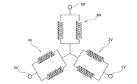
ステータコイル3は、平角線からなる導線を集中巻することで構成される。平角線の表面には、隣接する平角線間の絶縁を確保するためにエナメル加工が施されている。ステータコイル3は、W相のコイル3W、U相のコイル3U、V相のコイル3Vを有しており、各相コイル3W,3U,3Vは、単コイルW1〜W5、U1〜U5、V1〜V5から構成される。単コイルW1〜W5、U1〜U5、V1〜V5は、平角線からなる導線を一つのティースに巻回することで構成される。各単コイルW1〜W5、U1〜U5、V1〜V5は、周方向に繰り返し並ぶようにティースにそれぞれ配置されている。
The
複数の同相の単コイルW1〜W5、U1〜U5、V1〜V5を結線して構成される各相コイル3W,3U,3Vの各他端には、入力端子5W,5U,5Vがそれぞれ接続されている。入力端子5W,5U,5Vには、3相交流電力を出力する図示しないインバータが接続される。
図2に示すように、各相コイル3W,3U,3Vの各一端は、互いに接合されて中性点を構成する。各相コイル3W,3U,3Vは、入力端子5W,5U,5Vと中性点との間で並列接続されて2Y結線(並列スター結線)される。すなわち、W相のコイル3Wは、単コイルW1〜W5が2組に分割されて、各組が並列接続されている。単コイルW1〜W5を2組に分割するには、回転電機の仕様等に基づいて、例えば、単コイルW1〜W3を直列接続した組と単コイルW4,W5を直列接続した組とに分割する。または、単コイルW1〜W3を並列接続した組と単コイルW4,W5を並列接続した組とに分割する。他の単コイルU1〜U5、V1〜V5についても同様である。なお、コイルの個数は5つに限定されない。
As shown in FIG. 2, each one end of each
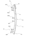
図3に示すように、コイルエンド3aの外周面には、各相コイル3W,3U,3Vの各一端がそれぞれ接続される中性点バスバ6が溶接によって固定される。図3、4に示すように、中性点バスバ6は、コイルエンド3aの外周面に沿う曲率で湾曲した帯状の本体部61と、この本体部61の長手方向の側面における一端部61a、中央部61b、他端部61cから屈曲して延出した複数の端子62と、本体部61の一端部61aにU字状に折り曲げられたクリップ63とを備えている。中性点バスバ6は、導電性及び熱伝導性に優れた金属、例えば、銅からなる平角導線により構成される。この平角導線を打抜き加工や曲げ加工することによって、本体部61、端子62、クリップ63が形成される。なお、クリップ63を中性点バスバ6と一体形成しているが、クリップ63を別体として中性点バスバ6に取り付けてもよい。
As shown in FIG. 3, a neutral
複数の端子62は、W相のコイル3Wが2分割された2組にそれぞれ対応する2つの端子62W1,62W2と、U相のコイル3Uが2分割された2組にそれぞれ対応する2つの端子62U1,62U2と、V相のコイル3Vが2分割された2組にそれぞれ対応する2つの端子62V1,62V2との合計6つの端子から構成される。本体部61は6つの端子62W1,62W2,62U1,62U2,62V1,62V2を備えるので、これら端子幅に対して本体部61の帯状部分は幅広く設定されて強度が保たれている。
The plurality of
クリップ63は、ステータコイル3の温度を検出する温度センサ7を挟み込んで保持している。クリップ63に温度センサ7を挟み込んだ際に、クリップ63と温度センサ7との間に隙間が生じた場合には樹脂を充填して温度センサ7を固定する。
The
温度センサ7は、中性点バスバ6を介してステータコイル3の温度を検出するサーミスタ素子7aと、サーミスタ素子7aから延出するリード線7bとを備えている。リード線7bは図示しない制御部に接続されており、サーミスタ素子7aによって検出されたステータコイル3の温度情報は制御部に送信されてステータコイル3への電流制御等に用いられる。
The
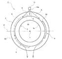
図5A、図5Bに示すように、ステータ1は、その回転軸線Lが略水平となるように車両に搭載されている。ステータ1の上方には、ステータコイル3に冷媒としての冷却オイルをコイルエンド3aに供給する冷却パイプ10が配置されている。冷却パイプ10のステータコイル3のコイルエンド3aに対向する位置には、コイルエンド3aの外周面に向けて冷却オイルを吐出する吐出口10aが設けられている。冷却パイプ10は、図示しない冷媒供給ポンプに接続されている。
As shown in FIGS. 5A and 5B, the stator 1 is mounted on the vehicle so that the rotation axis L thereof is substantially horizontal. Above the stator 1, a
冷媒供給ポンプによって冷却オイルが冷却パイプ10に圧送されると、図中矢印Aで示すように、冷却パイプ10の吐出口10aからコイルエンド3aに向けて、コイルエンド3aの上側外周面に冷却オイルが降り注ぐように供給される。冷却オイルはコイルエンド3aの内部や外周面を伝わってコイルエンド3aの下側外周面を流れて、図示しないオイルパンに流れ落ちる。
When the cooling oil is pumped to the
次に中性点バスバ6を固定する際のクリップ63の向きについて説明する。図5A、図5Bに示すように、中性点バスバ6は、回転軸線Lを通る水平面Hと、コイルエンド3aの外周面とが交差する位置に固定される。上述したように、ステータ1の上方からコイルエンド3aの外周面に冷却オイルが供給される場合には、クリップ63が、冷却オイルが供給される向き、すなわち、冷却オイルが流れてくる上流側を向くように、中性点バスバ6をコイルエンド3aの外周面に固定する。換言すると、冷却オイルがクリップ63のU字状に折り曲げられた箇所から降りかかるようにクリップ63の向きを規定して、中性点バスバ6をコイルエンド3aの外周面に固定する。
Next, the direction of the
また、図5Aにおいて、破線で示すように、中性点バスバ6が、回転軸線Lを通る水平面Hに対してコイルエンド3aの上側外周面に配置される場合も、クリップ63のU字状に折り曲げられた箇所が、冷却オイルが供給される向きを向くように中性点バスバ6を取り付ける。
5A, the neutral
さらに、図5Aにおいて、一点鎖線で示すように、中性点バスバ6が、回転軸線Lを通る水平面Hに対してコイルエンド3aの下側外周面に配置される場合においても、冷却オイルはコイルエンド3aの外周面や内部を伝わって、ステータコイル3の下方に流れることで冷却オイルが温度センサ7にあたるおそれがあるので、クリップ63のU字状に折り曲げられた箇所が、冷却オイルが流れてくる上流側を向くように中性点バスバ6を取り付ける。
Further, in FIG. 5A, as shown by the alternate long and short dash line, the cooling oil is coiled even when the neutral
以上、説明したように、コイルエンド3aの外周面に冷却オイルが供給されても、冷却オイルはクリップ63のU字状に折り曲げられた箇所に当たるようになり、温度センサ7へ直接当たることが抑制される。また、コイルエンド3aの外周面等を伝わる冷却オイルも温度センサ7に直接当たることが抑制される。よって、ステータコイル3や中性点バスバ6よりも温度センサ7の温度が低下することが抑制され、冷却オイルにより冷却されたステータコイル3や中性点バスバ6の温度を精度よく検出することができる。
As described above, even when the cooling oil is supplied to the outer peripheral surface of the
また、各相コイル3W,3U,3Vを2Y結線する場合、通常は1Y結線毎に中性点バスバを使用するが、上述した実施形態では、中性点バスバ6に、2Y結線する各相コイル3W,3U,3Vの各端子に対応する端子62U1,62U2,62V1,62V2,62W1,62W2を設けているので、1つの中性点バスバ6で対応することができ、また、この中性点バスバ6に保持される1つの温度センサ7で温度検出も可能になるので、小型化、低コストを図ることができる。
When each
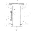
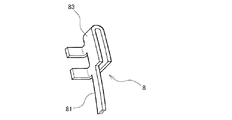
次に、中性点バスバの変形例について説明する。図6に示すように、中性点バスバ8のクリップ83が、帯状の本体部81の幅よりも広い幅広形状に形成される。クリップ83は、中性点バスバ8を形成する際に、幅広形状となるように打抜き加工して形成してもよいし、図4に示すクリップ63を形成した後に、このクリップ63をプレス加工によって押し伸ばして幅広形状としてもよい。このように、温度センサ7を保持するクリップ83を幅広形状とすることによって、温度センサ7への冷却オイルの降りかかりをより抑制することができる。
Next, a modified example of the neutral point bus bar will be described. As shown in FIG. 6, the
1 ステータ、2 ステータコア、2a ヨーク、3 ステータコイル、3W,3U,3V 各相コイル、3a コイルエンド、5W,5U,5V 入力端子、6,8 中性点バスバ、7 温度センサ、7a サーミスタ素子、7b リード線、10 冷却パイプ、10a 吐出口、61 本体部、61a 一端部、61b 中央部、61c 他端部、62 端子部、62U1,62U2,62V1,62V2,62W1,62W2 端子、63 ,83 クリップ。 1 stator, 2 stator core, 2a yoke, 3 stator coil, 3W, 3U, 3V phase coil, 3a coil end, 5W, 5U, 5V input terminal, 6, 8 neutral point bus bar, 7 temperature sensor, 7a thermistor element, 7b Lead wire, 10 Cooling pipe, 10a Discharge port, 61 Main body part, 61a One end part, 61b Center part, 61c Other end part, 62 terminal part, 62U1, 62U2, 62V1, 62V2, 62W1, 62W2 terminal, 63, 83 clips .
Claims (1)
前記中性点バスバは、その一端に前記コイルの温度を検出する温度センサを保持するU字状に折り曲げられたクリップを備え、前記クリップのU字状に折り曲げられた箇所が前記冷媒の流れの上流側となるように前記コイルエンドの外面に取り付けられることを特徴とする回転電機のステータ。 A stator of a rotating electrical machine including a three-phase coil to which a refrigerant is supplied to the outer surface of a coil end, and a neutral point bus bar to which one end of each phase coil is connected,
The neutral point bus bar includes a U-shaped clip that holds a temperature sensor that detects the temperature of the coil at one end, and the U-shaped portion of the clip is the flow of the refrigerant. A stator for a rotating electrical machine, wherein the stator is attached to an outer surface of the coil end so as to be on the upstream side.
Priority Applications (1)
| Application Number | Priority Date | Filing Date | Title |
|---|---|---|---|
| JP2014260365A JP2016123155A (en) | 2014-12-24 | 2014-12-24 | Stator for rotary electric machine |
Applications Claiming Priority (1)
| Application Number | Priority Date | Filing Date | Title |
|---|---|---|---|
| JP2014260365A JP2016123155A (en) | 2014-12-24 | 2014-12-24 | Stator for rotary electric machine |
Publications (1)
| Publication Number | Publication Date |
|---|---|
| JP2016123155A true JP2016123155A (en) | 2016-07-07 |
Family
ID=56329120
Family Applications (1)
| Application Number | Title | Priority Date | Filing Date |
|---|---|---|---|
| JP2014260365A Pending JP2016123155A (en) | 2014-12-24 | 2014-12-24 | Stator for rotary electric machine |
Country Status (1)
| Country | Link |
|---|---|
| JP (1) | JP2016123155A (en) |
Cited By (21)
| Publication number | Priority date | Publication date | Assignee | Title |
|---|---|---|---|---|
| JP2018007514A (en) * | 2016-07-08 | 2018-01-11 | トヨタ自動車株式会社 | Rotary electric machine |
| JP2018121389A (en) * | 2017-01-23 | 2018-08-02 | トヨタ自動車株式会社 | Stator of rotary electric machine |
| JP2019041440A (en) * | 2017-08-22 | 2019-03-14 | トヨタ自動車株式会社 | Stator for rotary electric machine |
| WO2019062923A1 (en) * | 2017-09-29 | 2019-04-04 | 比亚迪股份有限公司 | Stator assembly, and motor and vehicle having same |
| CN109586460A (en) * | 2017-09-29 | 2019-04-05 | 比亚迪股份有限公司 | Stator module and motor and vehicle with it |
| CN109586450A (en) * | 2017-09-29 | 2019-04-05 | 比亚迪股份有限公司 | Stator module and motor and vehicle with it |
| WO2019076540A1 (en) * | 2017-10-16 | 2019-04-25 | Robert Bosch Gmbh | Stator of an electric machine |
| EP3547508A1 (en) | 2018-03-28 | 2019-10-02 | Honda Motor Co., Ltd. | Rotary electric machine |
| DE102018208384A1 (en) * | 2018-05-28 | 2019-11-28 | Zf Friedrichshafen Ag | Stator of an electric machine with a temperature sensor and electric machine with such a stator |
| CN111009997A (en) * | 2018-10-05 | 2020-04-14 | 日本电产株式会社 | Motor and electric vehicle |
| WO2020216400A1 (en) * | 2019-04-26 | 2020-10-29 | Schaeffler Technologies AG & Co. KG | Electric machine |
| WO2021014067A1 (en) * | 2019-07-22 | 2021-01-28 | Nidec Psa Emotors | Electric machine provided with a temperature sensor |
| JP2021128010A (en) * | 2020-02-12 | 2021-09-02 | 三菱マテリアル株式会社 | Busbar module |
| WO2021191524A1 (en) * | 2020-03-25 | 2021-09-30 | Nidec Psa Emotors | Connection device for stator |
| WO2021192340A1 (en) * | 2020-03-27 | 2021-09-30 | 住友電装株式会社 | Busbar unit |
| CN113595331A (en) * | 2020-04-30 | 2021-11-02 | 丰田自动车株式会社 | Stator of rotating electric machine for vehicle |
| CN113924714A (en) * | 2019-06-06 | 2022-01-11 | 日本电产株式会社 | Stator unit and motor |
| US20220149691A1 (en) * | 2019-03-05 | 2022-05-12 | Zf Friedrichshafen Ag | Wiring configuration for a stator, temperature sensor device, and system for detecting a temperature |
| DE102022113230A1 (en) | 2021-05-28 | 2022-12-01 | Aisin Corporation | STATOR |
| EP3567705B1 (en) * | 2018-05-09 | 2024-02-21 | Volkswagen Aktiengesellschaft | Stator for electrical machine and method for producing same |
| JP7447551B2 (en) | 2020-03-02 | 2024-03-12 | 三菱マテリアル株式会社 | busbar module |
-
2014
- 2014-12-24 JP JP2014260365A patent/JP2016123155A/en active Pending
Cited By (32)
| Publication number | Priority date | Publication date | Assignee | Title |
|---|---|---|---|---|
| JP2018007514A (en) * | 2016-07-08 | 2018-01-11 | トヨタ自動車株式会社 | Rotary electric machine |
| JP2018121389A (en) * | 2017-01-23 | 2018-08-02 | トヨタ自動車株式会社 | Stator of rotary electric machine |
| JP2019041440A (en) * | 2017-08-22 | 2019-03-14 | トヨタ自動車株式会社 | Stator for rotary electric machine |
| WO2019062923A1 (en) * | 2017-09-29 | 2019-04-04 | 比亚迪股份有限公司 | Stator assembly, and motor and vehicle having same |
| CN109586460A (en) * | 2017-09-29 | 2019-04-05 | 比亚迪股份有限公司 | Stator module and motor and vehicle with it |
| CN109586450A (en) * | 2017-09-29 | 2019-04-05 | 比亚迪股份有限公司 | Stator module and motor and vehicle with it |
| CN109586450B (en) * | 2017-09-29 | 2022-01-07 | 比亚迪股份有限公司 | Stator assembly and motor and vehicle with same |
| CN109586460B (en) * | 2017-09-29 | 2021-12-07 | 比亚迪股份有限公司 | Stator assembly and motor and vehicle with same |
| WO2019076540A1 (en) * | 2017-10-16 | 2019-04-25 | Robert Bosch Gmbh | Stator of an electric machine |
| US20190305639A1 (en) * | 2018-03-28 | 2019-10-03 | Honda Motor Co., Ltd. | Rotary electric machine |
| CN110323855A (en) * | 2018-03-28 | 2019-10-11 | 本田技研工业株式会社 | Rotating electric machine |
| EP3547508A1 (en) | 2018-03-28 | 2019-10-02 | Honda Motor Co., Ltd. | Rotary electric machine |
| EP3567705B1 (en) * | 2018-05-09 | 2024-02-21 | Volkswagen Aktiengesellschaft | Stator for electrical machine and method for producing same |
| DE102018208384A1 (en) * | 2018-05-28 | 2019-11-28 | Zf Friedrichshafen Ag | Stator of an electric machine with a temperature sensor and electric machine with such a stator |
| CN111009997A (en) * | 2018-10-05 | 2020-04-14 | 日本电产株式会社 | Motor and electric vehicle |
| JP2020061814A (en) * | 2018-10-05 | 2020-04-16 | 日本電産株式会社 | Motor and electric vehicle |
| JP7326717B2 (en) | 2018-10-05 | 2023-08-16 | ニデック株式会社 | motors and electric vehicles |
| CN111009997B (en) * | 2018-10-05 | 2022-05-06 | 日本电产株式会社 | Motor and electric vehicle |
| US20220149691A1 (en) * | 2019-03-05 | 2022-05-12 | Zf Friedrichshafen Ag | Wiring configuration for a stator, temperature sensor device, and system for detecting a temperature |
| WO2020216400A1 (en) * | 2019-04-26 | 2020-10-29 | Schaeffler Technologies AG & Co. KG | Electric machine |
| CN113924714A (en) * | 2019-06-06 | 2022-01-11 | 日本电产株式会社 | Stator unit and motor |
| FR3099316A1 (en) * | 2019-07-22 | 2021-01-29 | Nidec Psa Emotors | Electric machine equipped with a temperature probe |
| WO2021014067A1 (en) * | 2019-07-22 | 2021-01-28 | Nidec Psa Emotors | Electric machine provided with a temperature sensor |
| JP2021128010A (en) * | 2020-02-12 | 2021-09-02 | 三菱マテリアル株式会社 | Busbar module |
| JP7434984B2 (en) | 2020-02-12 | 2024-02-21 | 三菱マテリアル株式会社 | busbar module |
| JP7447551B2 (en) | 2020-03-02 | 2024-03-12 | 三菱マテリアル株式会社 | busbar module |
| WO2021191524A1 (en) * | 2020-03-25 | 2021-09-30 | Nidec Psa Emotors | Connection device for stator |
| JP7396163B2 (en) | 2020-03-27 | 2023-12-12 | 住友電装株式会社 | busbar unit |
| WO2021192340A1 (en) * | 2020-03-27 | 2021-09-30 | 住友電装株式会社 | Busbar unit |
| CN113595331A (en) * | 2020-04-30 | 2021-11-02 | 丰田自动车株式会社 | Stator of rotating electric machine for vehicle |
| CN113595331B (en) * | 2020-04-30 | 2024-04-02 | 丰田自动车株式会社 | Stator for rotating electrical machine of vehicle |
| DE102022113230A1 (en) | 2021-05-28 | 2022-12-01 | Aisin Corporation | STATOR |
Similar Documents
| Publication | Publication Date | Title |
|---|---|---|
| JP2016123155A (en) | Stator for rotary electric machine | |
| US10263498B2 (en) | Cooled stator winding with temperature detection element configuration for improved accuracy | |
| JP6159483B2 (en) | Winding temperature estimation device for rotating electrical machine and winding temperature estimation method for rotating electrical machine | |
| US9887596B2 (en) | Rotating electric machine | |
| JP2013211945A (en) | On-vehicle motor and electric power steering device using the same | |
| US10038353B2 (en) | Dual-rotor electric rotating machine | |
| KR20160117547A (en) | Rotating electric machine | |
| JP2014090546A (en) | Dynamo-electric machine | |
| JP2019110676A (en) | Stator of rotary electric machine | |
| CN108141092A (en) | Motor | |
| JP6135774B2 (en) | Rotating electric machine | |
| CN110476331B (en) | Bus bar unit and motor having the same | |
| US20140102685A1 (en) | Device for cooling a component of an electrical machine using cooling coils | |
| JP5862970B2 (en) | Rotating electric machine | |
| JP2013219913A (en) | Rotary electric machine | |
| JP2015061465A (en) | Rotary electric machine stator | |
| JP2016129446A (en) | Rotary electric machine stator | |
| JP2019176626A (en) | Rotary electric machine | |
| JP2013223293A5 (en) | ||
| JP6443303B2 (en) | Rotating electrical machine stator | |
| JP2018061389A (en) | Stator of dynamo-electric machine | |
| JP2013055798A (en) | Weld structure of bus bar | |
| JP2017022820A (en) | Rotary electric machine | |
| JP2017034873A (en) | Electric motor | |
| JP2016032317A (en) | Rotary machine |