EP3567523B9 - Vermeidung von blinzeln und abgewendetem blick in fotografiebildern - Google Patents
Vermeidung von blinzeln und abgewendetem blick in fotografiebildern Download PDFInfo
- Publication number
- EP3567523B9 EP3567523B9 EP19182706.2A EP19182706A EP3567523B9 EP 3567523 B9 EP3567523 B9 EP 3567523B9 EP 19182706 A EP19182706 A EP 19182706A EP 3567523 B9 EP3567523 B9 EP 3567523B9
- Authority
- EP
- European Patent Office
- Prior art keywords
- images
- image
- camera
- subject
- blink
- Prior art date
- Legal status (The legal status is an assumption and is not a legal conclusion. Google has not performed a legal analysis and makes no representation as to the accuracy of the status listed.)
- Active
Links
Images


Classifications
-
- G—PHYSICS
- G06—COMPUTING OR CALCULATING; COUNTING
- G06V—IMAGE OR VIDEO RECOGNITION OR UNDERSTANDING
- G06V40/00—Recognition of biometric, human-related or animal-related patterns in image or video data
- G06V40/10—Human or animal bodies, e.g. vehicle occupants or pedestrians; Body parts, e.g. hands
- G06V40/18—Eye characteristics, e.g. of the iris
- G06V40/19—Sensors therefor
-
- H—ELECTRICITY
- H04—ELECTRIC COMMUNICATION TECHNIQUE
- H04N—PICTORIAL COMMUNICATION, e.g. TELEVISION
- H04N23/00—Cameras or camera modules comprising electronic image sensors; Control thereof
- H04N23/60—Control of cameras or camera modules
- H04N23/61—Control of cameras or camera modules based on recognised objects
- H04N23/611—Control of cameras or camera modules based on recognised objects where the recognised objects include parts of the human body
-
- H—ELECTRICITY
- H04—ELECTRIC COMMUNICATION TECHNIQUE
- H04N—PICTORIAL COMMUNICATION, e.g. TELEVISION
- H04N23/00—Cameras or camera modules comprising electronic image sensors; Control thereof
- H04N23/60—Control of cameras or camera modules
- H04N23/64—Computer-aided capture of images, e.g. transfer from script file into camera, check of taken image quality, advice or proposal for image composition or decision on when to take image
Definitions
- Certain aspects of the present disclosure generally relate to neural system engineering and, more particularly, to systems and methods for blink and averted gaze avoidance in photographic images.
- An artificial neural network which may comprise an interconnected group of artificial neurons (i.e., neuron models), is a computational device or represents a method to be performed by a computational device.
- Artificial neural networks may have corresponding structure and/or function in biological neural networks. Artificial neural networks, however, may provide innovative and useful computational techniques for certain applications in which traditional computational techniques are cumbersome, impractical, or inadequate. Because artificial neural networks can infer a function from observations, such networks are particularly useful in applications where the complexity of the task or data makes the design of the function by conventional techniques burdensome.
- a photograph may include a subject that is blinking and/or not looking at the camera. Accordingly, it is desirable to capture an image with each subject looking at the camera and also not blinking. Still, it may be difficult to capture a desired image when the image includes a large group of individuals, distracted individuals, young children, and/or individuals that may be actively avoiding the camera. Neural networking techniques may be employed to address these issues
- An example of related prior art is US 2004/170397 A1 (ONO SHUJI [JP]) 2 September 2004 ( 2004-09-02 ).
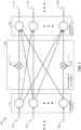
- FIGURE 1 illustrates an artificial neural system 100 with multiple levels of neurons in accordance with certain aspects of the present disclosure.
- the neural system 100 may have a level of neurons 102 coupled to another level of neurons 106 through a network of synaptic connections 104 (i.e., feed-forward connections).
- synaptic connections 104 i.e., feed-forward connections.
- FIGURE 1 illustrates an artificial neural system 100 with multiple levels of neurons in accordance with certain aspects of the present disclosure.
- the neural system 100 may have a level of neurons 102 coupled to another level of neurons 106 through a network of synaptic connections 104 (i.e., feed-forward connections).
- a network of synaptic connections 104 i.e., feed-forward connections.
- FIGURE 1 illustrates an artificial neural system 100 with multiple levels of neurons in accordance with certain aspects of the present disclosure.
- the neural system 100 may have a level of neurons 102 coupled to another level of neurons 106 through a network of synaptic connections 104 (i.e.,
- each neuron in the level 102 may receive an input signal 108 is generated by neurons of a previous level (not shown in FIGURE 1 ).
- the signal 108 may represent an input current of the level 102 neuron. This current may be accumulated on the neuron membrane to charge a membrane potential. When the membrane potential reaches its threshold value, the neuron may fire and generate an output spike that is transferred to the next level of neurons (e.g., the level 106). In some modeling approaches, the neuron may continuously transfer a signal to the next level of neurons. This signal is typically a function of the membrane potential. Such behavior can be simulated in hardware and/or software, including analog and digital implementations such as those described below.
- an action potential is the output spike that is generated when a neuron fires.
- This electrical signal is a relatively rapid, transient, nerve impulse, having an amplitude of roughly 100 mV and a duration of about 1 ms.
- every action potential has basically the same amplitude and duration, and thus, the information in the signal may be represented only by the frequency and number of spikes, or the time of spikes, rather than by the amplitude.
- the information carried by an action potential may be determined by the spike, the neuron that spiked, and the time of the spike relative to on other spike or spikes. The importance of the spike may be determined by a weight applied to a connection between neurons, as explained below.
- the transfer of spikes from one level of neurons to another may be achieved through a network of synaptic connections (or simply "synapses") 104, as illustrated in FIGURE 1 .
- neurons of level 102 may be considered presynaptic neurons and neurons of level 106 may be considered postsynaptic neurons.
- the synapses 104 may receive output signals (i.e., spikes) from the neurons of level 102 and scale those signals according to adjustable synaptic weights w 1 i , i + 1 , ... , w P i , i + 1 , where P is a total number of synaptic connections between the neurons of levels 102 and 106, and i is an indicator of the neuron level.
- i represents the neuron level 102
- i+1 represents the neuron level 106.
- the scaled signals may be combined as an input signal of each neuron in the level 106. Every neuron in the neuron level 106 may generate output spikes 110 based on the corresponding combined input signal.
- the output spikes 110 may be transferred to another level of neurons using another network of synaptic connections (not shown in FIGURE 1 ).
- Biological synapses can mediate either excitatory or inhibitory (hyperpolarizing) actions in postsynaptic neurons and can also serve to amplify neuronal signals.
- Excitatory signals depolarize the membrane potential (i.e., increase the membrane potential with respect to the resting potential). If enough excitatory signals are received within a certain time period to depolarize the membrane potential above a threshold, an action potential occurs in the postsynaptic neuron.
- inhibitory signals generally hyperpolarize (e.g., lower) the membrane potential.
- Inhibitory signals if strong enough, can counteract the sum of excitatory signals and prevent the membrane potential from reaching a threshold.
- synaptic inhibition can exert powerful control over spontaneously active neurons.
- a spontaneously active neuron refers to a neuron that spikes without further input, for example due to its dynamics or a feedback. By suppressing the spontaneous generation of action potentials in these neurons, synaptic inhibition can shape the pattern of firing in a neuron, which is generally referred to as sculpturing.
- the various synapses 104 may act as any combination of excitatory or inhibitory synapses, depending on the desired behavior.
- the neural system 100 may be simulated by a general purpose processor, a digital signal processor (DSP), an application specific integrated circuit (ASIC), a field programmable gate array (FPGA) or other programmable logic device (PLD), discrete gate or transistor logic, discrete hardware components, a software module executed by a processor, or any combination thereof.
- the neural system 100 may be utilized in a large range of applications, such as image and pattern recognition, machine learning, motor control, and the like.
- Each neuron in the neural system 100 may be implemented as a neuron circuit.
- the neuron membrane charged to the threshold value initiating the output spike may be implemented, for example, as a capacitor that integrates an electrical current flowing through it.
- the capacitor may be eliminated as the electrical current integrating device of the neuron circuit, and a smaller memory resistor (memristor) element may be used in its place.
- a smaller memory resistor (memristor) element may be used in its place.
- This approach may be applied in neuron circuits, as well as in various other applications where bulky capacitors are utilized as electrical current integrators.
- each of the synapses 104 may be implemented based on a memristor element, where synaptic weight changes may relate to changes of the memristor resistance. With nanometer feature-sized memristors, the area of a neuron circuit and synapses may be substantially reduced, which may make implementation of a large-scale neural system hardware implementation more practical.
- Functionality of a neural processor that emulates the neural system 100 may depend on weights of synaptic connections, which may control strengths of connections between neurons.
- the synaptic weights may be stored in a non-volatile memory in order to preserve functionality of the processor after being powered down.
- the synaptic weight memory may be implemented on a separate external chip from the main neural processor chip.
- the synaptic weight memory may be packaged separately from the neural processor chip as a replaceable memory card. This may provide diverse functionalities to the neural processor, where a particular functionality may be based on synaptic weights stored in a memory card currently attached to the neural processor.
- FIGURE 2 illustrates an exemplary diagram 200 of a processing unit (e.g., a neuron or neuron circuit) 202 of a computational network (e.g., a neural system or a neural network) in accordance with certain aspects of the present disclosure.
- the neuron 202 may correspond to any of the neurons of levels 102 and 106 from FIGURE 1 .
- the neuron 202 may receive multiple input signals 204 1 -204 N , which may be signals external to the neural system, or signals generated by other neurons of the same neural system, or both.
- the input signal may be a current, a conductance, a voltage, a real-valued, and/or a complex-valued.
- the input signal may comprise a numerical value with a fixed-point or a floating-point representation.
- These input signals may be delivered to the neuron 202 through synaptic connections that scale the signals according to adjustable synaptic weights 206 1 -206 N (W 1- W N ), where N may be a total number of input connections of the neuron 202.
- the neuron 202 may combine the scaled input signals and use the combined scaled inputs to generate an output signal 208 (i.e., a signal Y).
- the output signal 208 may be a current, a conductance, a voltage, a real-valued and/or a complex-valued.
- the output signal may be a numerical value with a fixed-point or a floating-point representation.
- the output signal 208 may be then transferred as an input signal to other neurons of the same neural system, or as an input signal to the same neuron 202, or as an output of the neural system.
- the processing unit (neuron) 202 may be emulated by an electrical circuit, and its input and output connections may be emulated by electrical connections with synaptic circuits.
- the processing unit 202 and its input and output connections may also be emulated by a software code.
- the processing unit 202 may also be emulated by an electric circuit, whereas its input and output connections may be emulated by a software code.
- the processing unit 202 in the computational network may be an analog electrical circuit.
- the processing unit 202 may be a digital electrical circuit.
- the processing unit 202 may be a mixed-signal electrical circuit with both analog and digital components.
- the computational network may include processing units in any of the aforementioned forms.
- the computational network (neural system or neural network) using such processing units may be utilized in a large range of applications, such as image and pattern recognition, machine learning, motor control, and the like.
- synaptic weights e.g., the weights w 1 i , i + 1 , ... , w P i , i + 1 from FIGURE 1 and/or the weights 206 1 -206 N from FIGURE 2
- the learning rule include, but are not limited to the spike-timing-dependent plasticity (STDP) learning rule, the Hebb rule, the Oja rule, the Bienenstock-Copper-Munro (BCM) rule, etc.
- STDP spike-timing-dependent plasticity
- BCM Bienenstock-Copper-Munro
- the weights may settle or converge to one of two values (i.e., a bimodal distribution of weights). This effect can be utilized to reduce the number of bits for each synaptic weight, increase the speed of reading and writing from/to a memory storing the synaptic weights, and to reduce power and/or processor consumption of the synaptic memory.
- synapse types may be non-plastic synapses (no changes of weight and delay), plastic synapses (weight may change), structural delay plastic synapses (weight and delay may change), fully plastic synapses (weight, delay and connectivity may change), and variations thereupon (e.g., delay may change, but no change in weight or connectivity).
- non-plastic synapses may not use plasticity functions to be executed (or waiting for such functions to complete).
- delay and weight plasticity may be subdivided into operations that may operate together or separately, in sequence or in parallel.
- Different types of synapses may have different lookup tables or formulas and parameters for each of the different plasticity types that apply. Thus, the methods would access the relevant tables, formulas, or parameters for the synapse's type.
- spike-timing dependent structural plasticity may be executed independently of synaptic plasticity.
- Structural plasticity may be executed even if there is no change to weight magnitude (e.g., if the weight has reached a minimum or maximum value, or it is not changed due to some other reason)
- s structural plasticity i.e., an amount of delay change
- structural plasticity may be set as a function of the weight change amount or based on conditions relating to bounds of the weights or weight changes. For example, a synapse delay may change only when a weight change occurs or if weights reach zero but not if they are at a maximum value.
- Plasticity is the capacity of neurons and neural networks in the brain to change their synaptic connections and behavior in response to new information, sensory stimulation, development, damage, or dysfunction. Plasticity is important to learning and memory in biology, as well as for computational neuroscience and neural networks. Various forms of plasticity have been studied, such as synaptic plasticity (e.g., according to the Hebbian theory), spike-timing-dependent plasticity (STDP), non-synaptic plasticity, activity-dependent plasticity, structural plasticity and homeostatic plasticity.
- synaptic plasticity e.g., according to the Hebbian theory
- STDP spike-timing-dependent plasticity
- non-synaptic plasticity non-synaptic plasticity
- activity-dependent plasticity e.g., structural plasticity and homeostatic plasticity.
- STDP is a learning process that adjusts the strength of synaptic connections between neurons.
- the connection strengths are adjusted based on the relative timing of a particular neuron's output and received input spikes (i.e., action potentials).
- LTP long-term potentiation
- LTD long-term depression
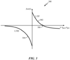
- FIGURE 3 illustrates an exemplary diagram 300 of a synaptic weight change as a function of relative timing of presynaptic and postsynaptic spikes in accordance with the STDP.
- a negative offset ⁇ may be applied to the LTP (causal) portion 302 of the STDP graph.
- the offset value ⁇ can be computed to reflect the frame boundary.
- a first input spike (pulse) in the frame may be considered to decay over time either as modeled by a postsynaptic potential directly or in terms of the effect on neural state.
- a second input spike (pulse) in the frame is considered correlated or relevant to a particular time frame
- the relevant times before and after the frame may be separated at that time frame boundary and treated differently in plasticity terms by offsetting one or more parts of the STDP curve such that the value in the relevant times may be different (e.g., negative for greater than one frame and positive for less than one frame).
- the negative offset ⁇ may be set to offset LTP such that the curve actually goes below zero at a pre-post time greater than the frame time and it is thus part of LTD instead of LTP.
- a good neuron model may have rich potential behavior in terms of two computational regimes: coincidence detection and functional computation. Moreover, a good neuron model should have two elements to allow temporal coding: arrival time of inputs affects output time and coincidence detection can have a narrow time window. Finally, to be computationally attractive, a good neuron model may have a closed-form solution in continuous time and stable behavior including near attractors and saddle points.
- a useful neuron model is one that is practical and that can be used to model rich, realistic and biologically-consistent behaviors, as well as be used to both engineer and reverse engineer neural circuits.
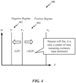
- the dynamics of the model 400 may be divided into two (or more) regimes. These regimes may be called the negative regime 402 (also interchangeably referred to as the leaky-integrate-and-fire (LIF) regime, not to be confused with the LIF neuron model) and the positive regime 404 (also interchangeably referred to as the anti-leaky-integrate-and-fire (ALIF) regime, not to be confused with the ALIF neuron model).
- the negative regime 402 the state tends toward rest ( v _ ) at the time of a future event.
- the model In this negative regime, the model generally exhibits temporal input detection properties and other sub-threshold behavior.
- the state tends toward a spiking event ( v s ).
- the model In this positive regime, the model exhibits computational properties, such as incurring a latency to spike depending on subsequent input events. Formulation of dynamics in terms of events and separation of the dynamics into these two regimes are fundamental characteristics of the model.
- An event update is an update where states are updated based on events or "event update” (at particular moments).
- a step update is an update when the model is updated at intervals (e.g., 1ms). This does not necessarily utilize iterative methods or Numerical methods.
- An event-based implementation is also possible at a limited time resolution in a step-based simulator by only updating the model if an event occurs at or between steps or by "step-event" update.
- aspects of the present disclosure are directed to mitigating blinks and averted gazes in captured images. Such processing is implemented with a neural network.
- a photograph may include a subject that is blinking and/or not looking at the camera. Accordingly, it is desirable to capture an image with each subject looking at the camera and also not blinking. Still, it may be difficult to capture a desired image when the image includes a large group of individuals, distracted individuals, young children, and/or individuals that may be actively avoiding the camera.
- a desired image refers to an image of one or more subjects that are not blinking and are also looking at the camera.
- aspects of the present application are not limited to an image in which all subjects are not blinking and looking at the camera.
- aspects are also contemplated for a threshold to capture an image when a number of subjects are not blinking and also looking at the camera. For example, in a group photograph, the image may be captured when a threshold percentage, such as eighty percent, of the subjects in the image are looking at the camera and not blinking.
- a photographer captures multiple images and manually searches the captured images to select one or more images with each subject looking towards the camera and also not blinking. Additionally, or alternatively, images with blinking subjects may be corrected with post-processing applications.
- some cameras include a burst mode for capturing multiple images in a short duration. Still, in a conventional camera, all of the images captured during the burst mode are stored in memory for post-processing or user selection. That is, conventional cameras capture multiple images that are post-processed and/or manually selected to obtain a desirable image including subjects that are not blinking and do not have an averted gaze.
- aspects of the present disclosure are directed to automatically determining whether a subject is blinking and/or has an averted gaze and adjusting the timing of the camera shutter to capture an image when a subject is looking at the camera without blinking.
- the determining of a blink or averted gaze is processed in real time.
- the time adjustment is based on an estimated time when a subject is looking at the camera without blinking.
- Neural networks may perform machine learning and object recognition. Specifically, neural networks may recognize facial features and perform iris detection to determine when a subject has a camera centered gaze and is also not blinking.
- the neural networks may include one or more feature extraction layers followed by a learning layer to enable blink and averted gaze avoidance in captured images.
- nodes, such as neurons, in each layer may encode features in the form of a temporal features pattern.
- aspects of the present disclosure are directed to blink avoidance and averted gaze avoidance in photographic images.
- the blink detection analysis and gaze direction analysis estimate a time to schedule the shutter of the camera so that a blink-free and camera-centered gaze is captured for the one or more subjects in a photo.
- the camera-centered gaze refers to the gaze of a subject that is looking towards the camera.
- facial detection may determine the presence and/or location of a face to initiate iris detection.
- Blink detection may be based on the iris detection and may determine whether two irises are detected in a face.
- gaze direction is determined by co-registering the face location and the iris location.
- the shutter actuates when a blink is not detected and the gaze is towards the camera.
- the shutter may be scheduled to actuate at an estimated time in the future to capture the image. The estimated time may be based on a time determined for an average blink and/or an average time of a diverted gaze.
- the camera determines if a blink and/or diverted gaze is/are present before capturing the image after the estimated time has lapsed. That is, before the shutter is scheduled to open, the blink detection may be executed to determine that a blink and/or diverted gaze is/are no longer present.
- the camera may periodically check for gaze direction. Additionally or alternatively, a future gaze direction may be predicted based on prior gaze location information so that the shutter is scheduled for an estimated time when the gaze will be towards the camera. Moreover, in some cases, time delays may not be desirable. Therefore, the camera may be configured to capture multiple images within a time period, such as in burst mode, when a blink and/or a gaze is/are detected. In one configuration, the burst mode is automatically activated without a user input for capturing multiple images within a time period. Furthermore, in one configuration, automatic face and iris detection is performed on the captured images to automatically delete temporarily stored images with blinks and/or averted gazes. That is, the camera may only save blink-free and camera-centered gaze images.
- aspects of the present disclosure are specified to capture and/or store blink-free and/or camera-centered gaze images based on real-time blink detection and/or gaze detection. Accordingly, aspects of the present disclosure mitigate storage of redundant images and improve the storage space for devices, such as smart phones.
- FIGURE 5 is a flow diagram illustrating a method 500 of blink avoidance and averted gaze avoidance in accordance with aspects of the present disclosure, not covered by the claimed invention.
- an input is received to actuate a shutter of a camera.
- the input may be an external input, such as a user input, or an internal input, such as a camera timer.
- facial detection and/or iris detection is/are initiated in response to the input received at block 510. For example, facial detection may be triggered to determine a facial location of the subjects in view of the camera. Additionally, iris detection may be performed in response to detection of the facial location.
- the device determines whether a blink and/or an averted gaze is/are detected.
- the blink and/or averted gaze may be detected based on the iris detection.
- the camera shutter is scheduled to actuate at a future time at block 516.
- the future time may be an estimated time period based on an estimated time when the gaze direction of the subjects is towards the camera and when the eyes of the each subject are open.
- the facial detection and iris detection of block 512 and/or blink or averted gaze detection of block 514 are performed until the subjects are not blinking and/or are also looking toward the camera. That is, the process of blocks 512, 514, and 516 are performed until a desirable image is captured. Accordingly, when a blink and averted gaze is not detected, the camera shutter is actuated to capture an image of the subjects at block 520. Furthermore, at block 522, the image is stored. In this configuration, the timing of the shutter actuation is adjusted in real-time to capture the moment when subjects are gazing at the camera without blinking.
- the shutter of the camera may be activated at block 520 to capture the image. That is, in this configuration, the camera does not perform a subsequent facial detection and iris detection prior to capturing the image. Furthermore, at block 522, the image is stored.
- a subject may be blinking even when their gaze is towards the camera. Therefore, actuation of the camera shutter may be delayed for an estimated time period so that the image is captured when the subject is not blinking.
- the estimated time period may be based on an estimated blink time and/or averted gaze time.
- the estimated times may be based on learned timing for the blink and/or averted gaze. For example, an average blink length may be eight-hundred milliseconds.
- the estimated time period may be set to time that is greater than eight-hundred milliseconds, such as one-thousand milliseconds.
- FIGURE 6 illustrates a method 600 of blink and averted gaze avoidance in photographic images in accordance with the claimed invention.
- an image capturing device determines whether a blink and an averted gaze of one or more subjects is detected.
- an image of the subjects is captured when the subjects are gazing at the camera without blinking.
- a camera shutter is actuated to capture multiple images of the subjects.
- desirable images are identified from the captured images.
- the desirable images are images with one or more subjects gazing at the camera without blinking.
- a neural network is trained to recognize features of an averted gaze as well as perform iris detection to identify the images in which the subjects are gazing at the camera without blinking.
- the desirable images are stored.
- images with subjects having an averted gaze and/or blinking eyes are deleted to reduce the storage of undesirable images.
- FIGURE 7 illustrates a method 700 for blink and averted gaze mitigation in stored images according to an aspect of the claimed invention.
- an input is received to actuate a shutter of a camera.
- the input may be an external input, such as a user input, or an internal input, such as a camera timer.
- facial detection and/or iris detection is/are initiated in response to the input received at block 710. For example, facial detection may be triggered to determine a facial location of the subjects in view of the camera. Moreover, iris detection may be performed in response to detection of the facial location. Additionally or alternatively, facial recognition and iris detection may be activated when facial movement of the subject is detected.
- the camera determines whether a blink and an averted gaze is/are detected.
- the blink and/or averted gaze may be detected based on the iris detection.
- a camera shutter is actuated N times to capture a burst of images of the subjects, at block 720.
- face and iris detection is performed to discard images so that desirable images can be identified from the captured burst of images at block 724.
- the desirable images are images with one or more subject(s) gazing at the camera without blinking.
- the desirable images are stored.
- the camera shutter is actuated at block 716 to capture an image.
- the image is stored at block 718.
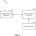
- FIGURE 8 illustrates an example implementation 800 of the aforementioned blink and averted gaze avoidance in photographic images using a general-purpose processor 802 in accordance with certain aspects of the present disclosure.
- Variables neural signals
- synaptic weights may be stored in a memory block 804
- instructions executed at the general-purpose processor 802 may be loaded from a program memory 806.
- the instructions loaded into the general-purpose processor 802 may comprise code for blink and averted gaze avoidance.
- FIGURE 9 illustrates an example implementation 900 of the aforementioned blink and averted gaze avoidance in photographic images
- a memory 902 can be interfaced via an interconnection network 904 with individual (distributed) processing units (neural processors) 909 of a computational network (neural network) in accordance with certain aspects of the present disclosure.
- Variables (neural signals), synaptic weights, system parameters associated with the computational network (neural network) delays, frequency bin information, and histogram information may be stored in the memory 902, and may be loaded from the memory 902 via connection(s) of the interconnection network 904 into each processing unit (neural processor) 909.
- the processing unit 909 may be configured to provide blink and averted gaze avoidance in photographic images.
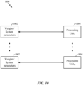
- FIGURE 10 illustrates an example implementation 1000 of the aforementioned blink and averted gaze avoidance in photographic images.
- one memory bank 1002 may be directly interfaced with one processing unit 1004 of a computational network (neural network).
- Each memory bank 1002 may store variables (neural signals), synaptic weights, and/or system parameters associated with a corresponding processing unit (neural processor) 1004 delays, frequency bin information, and histogram information.
- the processing unit 1004 may be configured to provide facial recognition and iris detection of a subject, and/or transform a subject representation to a canonical form based on a reference feature.
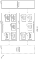
- FIGURE 11 illustrates an example implementation of a neural network 1100 configured to provide blink and averted gaze avoidance in photographic images in accordance with certain aspects of the present disclosure.
- the neural network 1100 may have multiple local processing units 1102 that may perform various operations of methods described herein.
- Each local processing unit 1102 may comprise a local state memory 1104 and a local parameter memory 1106 that store parameters of the neural network.
- the local processing unit 1102 may have a local (neuron) model program (LMP) memory 1110 for storing a local model program, a local learning program (LLP) memory 1110 for storing a local learning program, and a local connection memory 1112.
- LMP local (neuron) model program
- LLP local learning program
- each local processing unit 1102 may be interfaced with a configuration processor unit 1114 for providing configurations for local memories of the local processing unit, and with a routing connection processing unit 1116 that provide routing between the local processing units 1102.
- a neuron model is configured for blink and averted gaze avoidance in photographic images.
- the neuron model includes detecting means and scheduling means.
- the detecting means, and/or scheduling means may be the general-purpose processor 802, program memory 806, memory block 804, memory 902, interconnection network 904, processing units 909, processing unit 1004, local processing units 1102, and or the routing connection processing units 1116 configured to perform the functions recited.
- the aforementioned means may be any module or any apparatus configured to perform the functions recited by the aforementioned means.
- a neuron model is configured for blink and averted gaze avoidance in photograph images.
- the neuron model includes activating means and storing means.
- the activating means and/or the storing means may be the general-purpose processor 802, program memory 806, memory block 804, memory 902, interconnection network 904, processing units 909, processing unit 1004, local processing units 1102, and or the routing connection processing units 1116 configured to perform the functions recited.
- the aforementioned means may be any module or any apparatus configured to perform the functions recited by the aforementioned means.
- each local processing unit 1102 may be configured to determine parameters of the neural network based upon desired one or more functional features of the neural network, and develop the one or more functional features towards the desired functional features as the determined parameters are further adapted, tuned and updated.
- FIGURE 12 is a flow diagram illustrating a method 1200 of blink avoidance and averted gaze avoidance in accordance with aspects of the present disclosure, not covered by the claimed invention.
- a camera detects an averted gaze and/or one or more closed eyes of a subject in response to receiving an input to actuate a camera shutter.
- a neural network may be trained to provide facial recognition and iris detection to identify a blink or an averted gaze.
- the camera schedules an actuation of the camera shutter to a future estimated time period to capture an image of the subject when a gaze direction of the subject is centered and/or both eyes of the subject are open.
- the neural network may be trained to estimate the future time period in which the gaze direction of the subjects is towards the camera.
- the neural network may schedule the camera shutter to actuate during the approximated, future time period.
- the neural network may perform an additional blink and/or gaze check prior to capturing the image when the estimated future time has lapsed.
- delaying, during the future estimated time period may be delayed or adjusted if a subsequent blink and/or averted gaze is/are detected during the future estimated time period.
- FIGURE 13 is a flow diagram illustrating a method 1300 of blink avoidance and averted gaze avoidance in accordance with aspects of the present disclosure, not covered by the claimed invention.
- a camera actuates a shutter to capture a burst of images when the averted gaze of the subject is detected and/or one or more of the subject's eyes are closed.
- the averted gaze and/or closed eye detection may be performed after receiving an input to actuate the camera shutter and prior to capturing the image.
- the camera stores one or more one image from the burst of images having a gaze direction of the subject centered on the camera and having both eyes of the subject open.
- the various operations of methods described above may be performed by any suitable means capable of performing the corresponding functions.
- the means may include various hardware and/or software component(s) and/or module(s), including, but not limited to, a circuit, an application specific integrated circuit (ASIC), or processor.
- ASIC application specific integrated circuit
- determining encompasses a wide variety of actions. For example, “determining” may include calculating, computing, processing, deriving, investigating, looking up (e.g., looking up in a table, a database or another data structure), ascertaining and the like. Additionally, “determining” may include receiving (e.g., receiving information), accessing (e.g., accessing data in a memory) and the like. Furthermore, “determining” may include resolving, selecting, choosing, establishing and the like.
- a phrase referring to "at least one of" a list of items refers to any combination of those items, including single members.
- "at least one of: a, b, or c” is intended to cover: a, b, c, a-b, a-c, b-c, and a-b-c.
- DSP digital signal processor
- ASIC application specific integrated circuit
- FPGA field programmable gate array signal
- PLD programmable logic device
- a general-purpose processor may be a microprocessor, but in the alternative, the processor may be any commercially available processor, controller, microcontroller or state machine.
- a processor may also be implemented as a combination of computing devices, e.g., a combination of a DSP and a microprocessor, a plurality of microprocessors, one or more microprocessors in conjunction with a DSP core, or any other such configuration.
- a software module may reside in any form of storage medium that is known in the art. Some examples of storage media that may be used include random access memory (RAM), read only memory (ROM), flash memory, erasable programmable read-only memory (EPROM), electrically erasable programmable read-only memory (EEPROM), registers, a hard disk, a removable disk, a CD-ROM and so forth.
- RAM random access memory
- ROM read only memory
- EPROM erasable programmable read-only memory
- EEPROM electrically erasable programmable read-only memory
- registers a hard disk, a removable disk, a CD-ROM and so forth.
- a software module may comprise a single instruction, or many instructions, and may be distributed over several different code segments, among different programs, and across multiple storage media.
- a storage medium may be coupled to a processor such that the processor can read information from, and write information to, the storage medium. In the alternative, the storage medium may be integral to the processor.
- the methods disclosed herein comprise one or more steps or actions for achieving the described method.
- the method steps and/or actions may be interchanged with one another without departing from the scope of the claims.
- the order and/or use of specific steps and/or actions may be modified without departing from the scope of the claims.
- an example hardware configuration may comprise a processing system in a device.
- the processing system may be implemented with a bus architecture.
- the bus may include any number of interconnecting buses and bridges depending on the specific application of the processing system and the overall design constraints.
- the bus may link together various circuits including a processor, machine-readable media, and a bus interface.
- the bus interface may be used to connect a network adapter, among other things, to the processing system via the bus.
- the network adapter may be used to implement signal processing functions.
- a user interface e.g., keypad, display, mouse, joystick, etc.
- the bus may also link various other circuits such as timing sources, peripherals, voltage regulators, power management circuits, and the like, which are well known in the art, and therefore, will not be described any further.
- the processor may be responsible for managing the bus and general processing, including the execution of software stored on the machine-readable media.
- the processor may be implemented with one or more general-purpose and/or special-purpose processors. Examples include microprocessors, microcontrollers, DSP processors, and other circuitry that can execute software.
- Software shall be construed broadly to mean instructions, data, or any combination thereof, whether referred to as software, firmware, middleware, microcode, hardware description language, or otherwise.
- Machine-readable media may include, by way of example, random access memory (RAM), flash memory, read only memory (ROM), programmable read-only memory (PROM), erasable programmable read-only memory (EPROM), electrically erasable programmable Read-only memory (EEPROM), registers, magnetic disks, optical disks, hard drives, or any other suitable storage medium, or any combination thereof.
- RAM random access memory
- ROM read only memory
- PROM programmable read-only memory
- EPROM erasable programmable read-only memory
- EEPROM electrically erasable programmable Read-only memory
- registers magnetic disks, optical disks, hard drives, or any other suitable storage medium, or any combination thereof.
- the machine-readable media may be embodied in a computer-program product.
- the computer-program product may comprise packaging materials.
- the machine-readable media may be part of the processing system separate from the processor.
- the machine-readable media, or any portion thereof may be external to the processing system.
- the machine-readable media may include a transmission line, a carrier wave modulated by data, and/or a computer product separate from the device, all which may be accessed by the processor through the bus interface.
- the machine-readable media, or any portion thereof may be integrated into the processor, such as the case may be with cache and/or general register files.
- the various components discussed may be described as having a specific location, such as a local component, they may also be configured in various ways, such as certain components being configured as part of a distributed computing system.
- the processing system may be configured as a general-purpose processing system with one or more microprocessors providing the processor functionality and external memory providing at least a portion of the machine-readable media, all linked together with other supporting circuitry through an external bus architecture.
- the processing system may comprise one or more neuromorphic processors for implementing the neuron models and models of neural systems described herein.
- the processing system may be implemented with an application specific integrated circuit (ASIC) with the processor, the bus interface, the user interface, supporting circuitry, and at least a portion of the machine-readable media integrated into a single chip, or with one or more field programmable gate arrays (FPGAs), programmable logic devices (PLDs), controllers, state machines, gated logic, discrete hardware components, or any other suitable circuitry, or any combination of circuits that can perform the various functionality described throughout this disclosure.
- ASIC application specific integrated circuit
- FPGAs field programmable gate arrays
- PLDs programmable logic devices
- controllers state machines, gated logic, discrete hardware components, or any other suitable circuitry, or any combination of circuits that can perform the various functionality described throughout this disclosure.
- the machine-readable media may comprise a number of software modules.
- the software modules include instructions that, when executed by the processor, cause the processing system to perform various functions.
- the software modules may include a transmission module and a receiving module.
- Each software module may reside in a single storage device or be distributed across multiple storage devices.
- a software module may be loaded into RAM from a hard drive when a triggering event occurs.
- the processor may load some of the instructions into cache to increase access speed.
- One or more cache lines may then be loaded into a general register file for execution by the processor.
- Computer-readable media include both computer storage media and communication media including any medium that facilitates transfer of a computer program from one place to another.
- a storage medium may be any available medium that can be accessed by a computer.
- such computer-readable media can comprise RAM, ROM, EEPROM, CD-ROM or other optical disk storage, magnetic disk storage or other magnetic storage devices, or any other medium that can be used to carry or store desired program code in the form of instructions or data structures and that can be accessed by a computer.
- any connection is properly termed a computer-readable medium.
- Disk and disc include compact disc (CD), laser disc, optical disc, digital versatile disc (DVD), floppy disk, and Blu-ray ® disc where disks usually reproduce data magnetically, while discs reproduce data optically with lasers.
- computer-readable media may comprise non-transitory computer-readable media (e.g., tangible media).
- computer-readable media may comprise transitory computer- readable media (e.g., a signal). Combinations of the above should also be included within the scope of computer-readable media.
- certain aspects may comprise a computer program product for performing the operations presented herein.
- a computer program product may comprise a computer-readable medium having instructions stored (and/or encoded) thereon, the instructions being executable by one or more processors to perform the operations described herein.
- the computer program product may include packaging material.
- modules and/or other appropriate means for performing the methods and techniques described herein can be downloaded and/or otherwise obtained by a user terminal and/or base station as applicable.
- a user terminal and/or base station can be coupled to a server to facilitate the transfer of means for performing the methods described herein.
- various methods described herein can be provided via storage means (e.g., RAM, ROM, a physical storage medium such as a compact disc (CD) or floppy disk, etc.), such that a user terminal and/or base station can obtain the various methods upon coupling or providing the storage means to the device.
- storage means e.g., RAM, ROM, a physical storage medium such as a compact disc (CD) or floppy disk, etc.
- CD compact disc
- floppy disk etc.
- any other suitable technique for providing the methods and techniques described herein to a device can be utilized.
Landscapes
- Engineering & Computer Science (AREA)
- Multimedia (AREA)
- Signal Processing (AREA)
- Human Computer Interaction (AREA)
- General Health & Medical Sciences (AREA)
- Ophthalmology & Optometry (AREA)
- Health & Medical Sciences (AREA)
- Physics & Mathematics (AREA)
- General Physics & Mathematics (AREA)
- Theoretical Computer Science (AREA)
- Image Analysis (AREA)
- Details Of Cameras Including Film Mechanisms (AREA)
- Studio Devices (AREA)
Claims (15)
- Ein Verfahren zum Aufnehmen, mit einer Kamera, eines gewünschten Bilds aus mehreren Bildern einer Person, aufweisend:Bestimmen (610, 714), dass eine Person eines Bilds keine Blickrichtung zu einer Kamera mit einem geöffneten Auge aufweist, undin Antwort auf das Bestimmen, dass die Person des Bilds keine Blickrichtung zu der Kamera mit einem geöffneten Auge aufweist:Aufnehmen (614; 720) eines Bursts von Bildern der Person,Identifizieren (616; 724) wenigstens eines Bilds aus dem Burst von Bildern mit einem künstlichen neuronalen Netz, das für eine Blinzelerfassung und eine Abgewendeter-Blick-Erfassung trainiert ist, wobei das identifizierte wenigstens eine Bild die Person mit dem Auge in einem geöffneten Zustand und zu der die mehreren Bilder aufnehmenden Kamera blickend abbildet, undSpeichern (618; 718) des wenigstens einen Bilds.
- Verfahren nach Anspruch 1, wobei das künstliche neuronale Netz weiterhin für eine Iriserfassung trainiert ist.
- Verfahren nach Anspruch 1 oder 2, das weiterhin das Empfangen einer Benutzereingabe für das Aufnehmen eines Bilds aufweist.
- Verfahren nach einem der Ansprüche 1 bis 3, wobei der Burst von Bildern ohne eine Benutzereingabe für das Aufnehmen von mehreren Bildern aufgenommen wird.
- Verfahren nach Anspruch 4, wobei das künstliche neuronale Netz konfiguriert ist zum Erfassen von blinzelnden Augen in Echtzeit.
- Verfahren nach einem der Ansprüche 1 bis 5, das weiterhin das Löschen jedes Bilds aus dem Burst von Bildern, das das wenigstens ein Auge der Person in einem geschlossenen Zustand abbildet, aufweist.
- Verfahren nach einem der Ansprüche 1 bis 6, wobei der Burst von Bildern die Person mit einem abgewendeten Blick von einer die mehreren Bilder aufnehmenden Kamera abbildet.
- Eine Vorrichtung zum Aufnehmen, mit einer Kamera, eines gewünschten Bilds aus mehreren Bildern einer Person, aufweisend:Mittel, die konfiguriert sind zum Bestimmen (610, 714), ob eine Person eines Bilds keine Blickrichtung zu einer Kamera mit einem geöffneten Auge aufweist,Mittel, die konfiguriert sind zum Aufnehmen (614; 720), in Antwort auf das Bestimmen, dass die Person des Bilds keine Blickrichtung zu der Kamera mit einem geöffneten Auge aufweist, eines Bursts von Bildern der Person,ein künstliches neuronales Netz, das für eine Blinzelerfassung und eine Abgewendeter-Blick-Erfassung trainiert ist und konfiguriert ist zum Identifizieren (616; 724) wenigstens eines Bilds aus dem Burst von Bildern, wobei das identifizierte wenigstens eine Bild die Person mit dem Auge in einem geöffneten Zustand und zu der die mehreren Bilder aufnehmenden Kamera blickend abbildet, undMittel, die konfiguriert sind zum Speichern (618; 718) des wenigstens einen Bilds.
- Vorrichtung nach Anspruch 8, wobei das künstliche neuronale Netz weiterhin für eine Iriserfassung trainiert ist.
- Vorrichtung nach Anspruch 8 oder 9, die weiterhin Mittel, die konfiguriert sind zum Empfangen einer Benutzereingabe für das Aufnehmen eines Bilds, umfasst.
- Vorrichtung nach einem der Ansprüche 8 bis 10, wobei der Burst von Bildern ohne eine Benutzereingabe für das Aufnehmen von mehreren Bildern aufgenommen wird.
- Vorrichtung nach einem der Ansprüche 8 bis 11, wobei das künstliche neuronale Netz konfiguriert ist zum Erfassen von blinzelnden Augen in Echtzeit.
- Vorrichtung nach einem der Ansprüche 8 bis 12, das weiterhin Mittel, die konfiguriert sind zum Löschen jedes Bilds aus dem Burst von Bildern, das das wenigstens ein Auge der Person in einem geschlossenen Zustand abbildet, umfasst.
- Vorrichtung nach einem der Ansprüche 8 bis 13, wobei der Burst von Bildern die Person mit einem abgewendeten Blick von einer die mehreren Bilder aufnehmenden Kamera abbildet.
- Ein computerlesbares Medium mit computerausführbaren Befehlen, die die Vorrichtung von Anspruch 8 veranlassen zum Durchführen des Verfahrens eines der Ansprüche 1 bis 7.
Applications Claiming Priority (4)
| Application Number | Priority Date | Filing Date | Title |
|---|---|---|---|
| US201461950641P | 2014-03-10 | 2014-03-10 | |
| US14/520,710 US9549118B2 (en) | 2014-03-10 | 2014-10-22 | Blink and averted gaze avoidance in photographic images |
| EP15711349.9A EP3117368A1 (de) | 2014-03-10 | 2015-02-27 | Vermeidung von blinzeln und abgewendetem blick in fotografiebildern |
| PCT/US2015/018150 WO2015138169A1 (en) | 2014-03-10 | 2015-02-27 | Blink and averted gaze avoidance in photographic images |
Related Parent Applications (1)
| Application Number | Title | Priority Date | Filing Date |
|---|---|---|---|
| EP15711349.9A Division EP3117368A1 (de) | 2014-03-10 | 2015-02-27 | Vermeidung von blinzeln und abgewendetem blick in fotografiebildern |
Publications (4)
| Publication Number | Publication Date |
|---|---|
| EP3567523A1 EP3567523A1 (de) | 2019-11-13 |
| EP3567523B1 EP3567523B1 (de) | 2024-05-29 |
| EP3567523C0 EP3567523C0 (de) | 2024-05-29 |
| EP3567523B9 true EP3567523B9 (de) | 2024-11-20 |
Family
ID=54018690
Family Applications (2)
| Application Number | Title | Priority Date | Filing Date |
|---|---|---|---|
| EP15711349.9A Withdrawn EP3117368A1 (de) | 2014-03-10 | 2015-02-27 | Vermeidung von blinzeln und abgewendetem blick in fotografiebildern |
| EP19182706.2A Active EP3567523B9 (de) | 2014-03-10 | 2015-02-27 | Vermeidung von blinzeln und abgewendetem blick in fotografiebildern |
Family Applications Before (1)
| Application Number | Title | Priority Date | Filing Date |
|---|---|---|---|
| EP15711349.9A Withdrawn EP3117368A1 (de) | 2014-03-10 | 2015-02-27 | Vermeidung von blinzeln und abgewendetem blick in fotografiebildern |
Country Status (7)
| Country | Link |
|---|---|
| US (1) | US9549118B2 (de) |
| EP (2) | EP3117368A1 (de) |
| JP (1) | JP6142097B1 (de) |
| KR (1) | KR101819880B1 (de) |
| CN (2) | CN110110677B (de) |
| CA (1) | CA2938135A1 (de) |
| WO (1) | WO2015138169A1 (de) |
Families Citing this family (14)
| Publication number | Priority date | Publication date | Assignee | Title |
|---|---|---|---|---|
| US10068127B2 (en) * | 2014-12-19 | 2018-09-04 | Iris Id, Inc. | Automatic detection of face and thereby localize the eye region for iris recognition |
| US20170126966A1 (en) * | 2015-10-29 | 2017-05-04 | Mediatek Inc. | Photography method using gaze detection |
| KR20180006133A (ko) * | 2016-07-08 | 2018-01-17 | 삼성전자주식회사 | 전자 장치 및 그의 동작 방법 |
| US10321050B2 (en) * | 2016-11-29 | 2019-06-11 | International Business Machines Corporation | Determining optimal photograph capture timing based on data from wearable computer eyewear devices |
| CN108513074B (zh) * | 2018-04-13 | 2020-08-04 | 京东方科技集团股份有限公司 | 自拍控制方法及装置、电子设备 |
| US10684681B2 (en) * | 2018-06-11 | 2020-06-16 | Fotonation Limited | Neural network image processing apparatus |
| JP7166837B2 (ja) * | 2018-08-09 | 2022-11-08 | オリンパス株式会社 | 教師データ作成装置、教師データ作成方法、教師データ作成プログラム、学習装置及び撮像装置 |
| JP7276424B2 (ja) | 2019-02-18 | 2023-05-18 | 日本電気株式会社 | 撮像装置、方法、システム、及びプログラム |
| EP3929859A4 (de) * | 2019-02-18 | 2022-04-13 | NEC Corporation | Bildverarbeitungsvorrichtung, -verfahren und -system und computerlesbares medium |
| CN117499656A (zh) | 2019-04-16 | 2024-02-02 | 北京字节跳动网络技术有限公司 | 帧内编解码模式下的矩阵推导 |
| JP7424375B2 (ja) * | 2019-05-21 | 2024-01-30 | ソニーグループ株式会社 | 画像処理装置、および画像処理方法、並びにプログラム |
| KR102698314B1 (ko) | 2019-05-22 | 2024-08-26 | 베이징 바이트댄스 네트워크 테크놀로지 컴퍼니, 리미티드 | 업샘플링을 이용한 행렬 기반 인트라 예측 |
| CN112036311A (zh) * | 2020-08-31 | 2020-12-04 | 北京字节跳动网络技术有限公司 | 基于眼部状态检测的图像处理方法、装置及存储介质 |
| JP7686276B2 (ja) * | 2021-09-30 | 2025-06-02 | 株式会社シグマ | 撮影方法 |
Family Cites Families (32)
| Publication number | Priority date | Publication date | Assignee | Title |
|---|---|---|---|---|
| JP3226641B2 (ja) * | 1992-02-04 | 2001-11-05 | 富士写真フイルム株式会社 | パターン学習方法 |
| JP3361980B2 (ja) * | 1997-12-12 | 2003-01-07 | 株式会社東芝 | 視線検出装置及びその方法 |
| US6204828B1 (en) * | 1998-03-31 | 2001-03-20 | International Business Machines Corporation | Integrated gaze/manual cursor positioning system |
| JP2000347277A (ja) * | 1999-06-03 | 2000-12-15 | Fuji Photo Film Co Ltd | カメラ及び撮影方法 |
| US7248300B1 (en) | 1999-06-03 | 2007-07-24 | Fujifilm Corporation | Camera and method of photographing good image |
| US7792335B2 (en) | 2006-02-24 | 2010-09-07 | Fotonation Vision Limited | Method and apparatus for selective disqualification of digital images |
| CA2616030A1 (en) * | 2005-07-20 | 2007-01-25 | Lab Partners Associates, Inc. | Wireless photographic communication system and method |
| US7804983B2 (en) * | 2006-02-24 | 2010-09-28 | Fotonation Vision Limited | Digital image acquisition control and correction method and apparatus |
| JP4999570B2 (ja) * | 2007-06-18 | 2012-08-15 | キヤノン株式会社 | 表情認識装置及び方法、並びに撮像装置 |
| JP4885084B2 (ja) * | 2007-07-19 | 2012-02-29 | 富士フイルム株式会社 | 撮像装置、撮像方法、撮像プログラム |
| US8022982B2 (en) * | 2008-01-02 | 2011-09-20 | Sony Ericsson Mobile Communications Ab | Camera system and method for operating a camera system |
| JP2009182485A (ja) * | 2008-01-29 | 2009-08-13 | Toshiba Corp | 撮影装置、撮影方法 |
| KR20090086754A (ko) * | 2008-02-11 | 2009-08-14 | 삼성디지털이미징 주식회사 | 디지털 영상 처리 장치 및 그 제어 방법 |
| JP5055166B2 (ja) | 2008-02-29 | 2012-10-24 | キヤノン株式会社 | 眼の開閉度判定装置、方法及びプログラム、撮像装置 |
| KR101448536B1 (ko) * | 2008-03-21 | 2014-10-08 | 삼성전자주식회사 | 디지털 촬영장치, 그 제어방법 및 제어방법을 실행시키기위한 프로그램을 저장한 기록매체 |
| JP5153434B2 (ja) * | 2008-04-22 | 2013-02-27 | キヤノン株式会社 | 情報処理装置及び情報処理方法 |
| CN101620359A (zh) * | 2008-07-04 | 2010-01-06 | 华晶科技股份有限公司 | 眼睛视线判断的方法 |
| JP4957711B2 (ja) * | 2008-12-02 | 2012-06-20 | オムロン株式会社 | 検出装置および方法、並びに、プログラム |
| JP5359266B2 (ja) | 2008-12-26 | 2013-12-04 | 富士通株式会社 | 顔認識装置、顔認識方法及び顔認識プログラム |
| US7819525B2 (en) * | 2009-02-15 | 2010-10-26 | International Business Machines Corporation | Automatic direct gaze detection based on pupil symmetry |
| JP4748244B2 (ja) * | 2009-03-31 | 2011-08-17 | カシオ計算機株式会社 | 画像選択装置、画像選択方法及びプログラム |
| US8482626B2 (en) * | 2009-04-07 | 2013-07-09 | Mediatek Inc. | Digital camera and image capturing method |
| CN101943982B (zh) * | 2009-07-10 | 2012-12-12 | 北京大学 | 基于被跟踪的眼睛运动的图像操作 |
| KR101642402B1 (ko) | 2010-02-01 | 2016-07-25 | 삼성전자주식회사 | 촬영 구도를 유도하는 디지털 영상 촬영 장치 및 방법 |
| EP2360620A1 (de) * | 2010-02-24 | 2011-08-24 | Research In Motion Limited | Augenzwinkervermeidung beim Bilderhalt in einer mobilen Kommunikationsvorrichtung mit digitaler Kamerafunktion |
| US20110205383A1 (en) * | 2010-02-24 | 2011-08-25 | Research In Motion Limited | Eye blink avoidance during image acquisition in a mobile communications device with digital camera functionality |
| KR101728042B1 (ko) | 2010-10-01 | 2017-04-18 | 삼성전자주식회사 | 디지털 촬영 장치 및 이의 제어 방법 |
| US9766698B2 (en) * | 2011-05-05 | 2017-09-19 | Nokia Technologies Oy | Methods and apparatuses for defining the active channel in a stereoscopic view by using eye tracking |
| JP5915000B2 (ja) | 2011-06-13 | 2016-05-11 | ソニー株式会社 | 情報処理装置及びプログラム |
| ES2495425T3 (es) | 2011-07-11 | 2014-09-17 | Accenture Global Services Limited | Detección de vida |
| US9596398B2 (en) * | 2011-09-02 | 2017-03-14 | Microsoft Technology Licensing, Llc | Automatic image capture |
| JP5854861B2 (ja) * | 2012-01-27 | 2016-02-09 | キヤノン株式会社 | 撮像装置、その制御方法、および制御プログラム |
-
2014
- 2014-10-22 US US14/520,710 patent/US9549118B2/en active Active
-
2015
- 2015-02-27 WO PCT/US2015/018150 patent/WO2015138169A1/en not_active Ceased
- 2015-02-27 KR KR1020167025461A patent/KR101819880B1/ko active Active
- 2015-02-27 JP JP2016556273A patent/JP6142097B1/ja not_active Expired - Fee Related
- 2015-02-27 CN CN201910393021.7A patent/CN110110677B/zh active Active
- 2015-02-27 EP EP15711349.9A patent/EP3117368A1/de not_active Withdrawn
- 2015-02-27 CA CA2938135A patent/CA2938135A1/en not_active Abandoned
- 2015-02-27 EP EP19182706.2A patent/EP3567523B9/de active Active
- 2015-02-27 CN CN201580011720.0A patent/CN106104568B/zh active Active
Also Published As
| Publication number | Publication date |
|---|---|
| CN110110677B (zh) | 2024-10-22 |
| CN106104568A (zh) | 2016-11-09 |
| CN110110677A (zh) | 2019-08-09 |
| EP3567523A1 (de) | 2019-11-13 |
| EP3567523B1 (de) | 2024-05-29 |
| KR20160132032A (ko) | 2016-11-16 |
| JP2017517165A (ja) | 2017-06-22 |
| CN106104568B (zh) | 2019-06-04 |
| EP3567523C0 (de) | 2024-05-29 |
| KR101819880B1 (ko) | 2018-01-19 |
| JP6142097B1 (ja) | 2017-06-07 |
| US20150256741A1 (en) | 2015-09-10 |
| WO2015138169A1 (en) | 2015-09-17 |
| EP3117368A1 (de) | 2017-01-18 |
| US9549118B2 (en) | 2017-01-17 |
| CA2938135A1 (en) | 2015-09-17 |
Similar Documents
| Publication | Publication Date | Title |
|---|---|---|
| EP3567523B1 (de) | Vermeidung von blinzeln und abgewendetem blick in fotografiebildern | |
| US9558442B2 (en) | Monitoring neural networks with shadow networks | |
| US10140573B2 (en) | Neural network adaptation to current computational resources | |
| US20150242745A1 (en) | Event-based inference and learning for stochastic spiking bayesian networks | |
| AU2015289877A1 (en) | Decomposing convolution operation in neural networks | |
| WO2014189970A2 (en) | Efficient hardware implementation of spiking networks | |
| WO2015088774A2 (en) | Neuronal diversity in spiking neural networks and pattern classification | |
| WO2015156989A2 (en) | Modulating plasticity by global scalar values in a spiking neural network | |
| WO2015148369A2 (en) | Invariant object representation of images using spiking neural networks | |
| CA2924468A1 (en) | Congestion avoidance in networks of spiking neurons | |
| WO2015148210A2 (en) | Plastic synapse management | |
| WO2015123460A1 (en) | Auditory source separation in a spiking neural network | |
| US9342782B2 (en) | Stochastic delay plasticity | |
| CA2926034A1 (en) | Dynamically assigning and examining synaptic delay |
Legal Events
| Date | Code | Title | Description |
|---|---|---|---|
| PUAI | Public reference made under article 153(3) epc to a published international application that has entered the european phase |
Free format text: ORIGINAL CODE: 0009012 |
|
| STAA | Information on the status of an ep patent application or granted ep patent |
Free format text: STATUS: THE APPLICATION HAS BEEN PUBLISHED |
|
| AC | Divisional application: reference to earlier application |
Ref document number: 3117368 Country of ref document: EP Kind code of ref document: P |
|
| AK | Designated contracting states |
Kind code of ref document: A1 Designated state(s): AL AT BE BG CH CY CZ DE DK EE ES FI FR GB GR HR HU IE IS IT LI LT LU LV MC MK MT NL NO PL PT RO RS SE SI SK SM TR |
|
| STAA | Information on the status of an ep patent application or granted ep patent |
Free format text: STATUS: REQUEST FOR EXAMINATION WAS MADE |
|
| 17P | Request for examination filed |
Effective date: 20200521 |
|
| RBV | Designated contracting states (corrected) |
Designated state(s): AL AT BE BG CH CY CZ DE DK EE ES FI FR GB GR HR HU IE IS IT LI LT LU LV MC MK MT NL NO PL PT RO RS SE SI SK SM TR |
|
| STAA | Information on the status of an ep patent application or granted ep patent |
Free format text: STATUS: EXAMINATION IS IN PROGRESS |
|
| 17Q | First examination report despatched |
Effective date: 20210726 |
|
| REG | Reference to a national code |
Ipc: G06V0040180000 Ref country code: DE Ref legal event code: R079 Ref document number: 602015088875 Country of ref document: DE Free format text: PREVIOUS MAIN CLASS: G06K0009000000 Ipc: G06V0040180000 |
|
| GRAP | Despatch of communication of intention to grant a patent |
Free format text: ORIGINAL CODE: EPIDOSNIGR1 |
|
| STAA | Information on the status of an ep patent application or granted ep patent |
Free format text: STATUS: GRANT OF PATENT IS INTENDED |
|
| RIC1 | Information provided on ipc code assigned before grant |
Ipc: G06V 40/18 20220101AFI20231207BHEP |
|
| INTG | Intention to grant announced |
Effective date: 20231222 |
|
| GRAS | Grant fee paid |
Free format text: ORIGINAL CODE: EPIDOSNIGR3 |
|
| GRAA | (expected) grant |
Free format text: ORIGINAL CODE: 0009210 |
|
| STAA | Information on the status of an ep patent application or granted ep patent |
Free format text: STATUS: THE PATENT HAS BEEN GRANTED |
|
| AC | Divisional application: reference to earlier application |
Ref document number: 3117368 Country of ref document: EP Kind code of ref document: P |
|
| AK | Designated contracting states |
Kind code of ref document: B1 Designated state(s): AL AT BE BG CH CY CZ DE DK EE ES FI FR GB GR HR HU IE IS IT LI LT LU LV MC MK MT NL NO PL PT RO RS SE SI SK SM TR |
|
| REG | Reference to a national code |
Ref country code: CH Ref legal event code: EP |
|
| REG | Reference to a national code |
Ref country code: IE Ref legal event code: FG4D |
|
| REG | Reference to a national code |
Ref country code: DE Ref legal event code: R096 Ref document number: 602015088875 Country of ref document: DE |
|
| U01 | Request for unitary effect filed |
Effective date: 20240612 |
|
| U07 | Unitary effect registered |
Designated state(s): AT BE BG DE DK EE FI FR IT LT LU LV MT NL PT SE SI Effective date: 20240621 |
|
| PG25 | Lapsed in a contracting state [announced via postgrant information from national office to epo] |
Ref country code: IS Free format text: LAPSE BECAUSE OF FAILURE TO SUBMIT A TRANSLATION OF THE DESCRIPTION OR TO PAY THE FEE WITHIN THE PRESCRIBED TIME-LIMIT Effective date: 20240929 |
|
| PG25 | Lapsed in a contracting state [announced via postgrant information from national office to epo] |
Ref country code: HR Free format text: LAPSE BECAUSE OF FAILURE TO SUBMIT A TRANSLATION OF THE DESCRIPTION OR TO PAY THE FEE WITHIN THE PRESCRIBED TIME-LIMIT Effective date: 20240529 |
|
| PG25 | Lapsed in a contracting state [announced via postgrant information from national office to epo] |
Ref country code: GR Free format text: LAPSE BECAUSE OF FAILURE TO SUBMIT A TRANSLATION OF THE DESCRIPTION OR TO PAY THE FEE WITHIN THE PRESCRIBED TIME-LIMIT Effective date: 20240830 |
|
| PG25 | Lapsed in a contracting state [announced via postgrant information from national office to epo] |
Ref country code: ES Free format text: LAPSE BECAUSE OF FAILURE TO SUBMIT A TRANSLATION OF THE DESCRIPTION OR TO PAY THE FEE WITHIN THE PRESCRIBED TIME-LIMIT Effective date: 20240529 |
|
| PG25 | Lapsed in a contracting state [announced via postgrant information from national office to epo] |
Ref country code: PL Free format text: LAPSE BECAUSE OF FAILURE TO SUBMIT A TRANSLATION OF THE DESCRIPTION OR TO PAY THE FEE WITHIN THE PRESCRIBED TIME-LIMIT Effective date: 20240529 |
|
| PG25 | Lapsed in a contracting state [announced via postgrant information from national office to epo] |
Ref country code: PL Free format text: LAPSE BECAUSE OF FAILURE TO SUBMIT A TRANSLATION OF THE DESCRIPTION OR TO PAY THE FEE WITHIN THE PRESCRIBED TIME-LIMIT Effective date: 20240529 Ref country code: NO Free format text: LAPSE BECAUSE OF FAILURE TO SUBMIT A TRANSLATION OF THE DESCRIPTION OR TO PAY THE FEE WITHIN THE PRESCRIBED TIME-LIMIT Effective date: 20240829 Ref country code: IS Free format text: LAPSE BECAUSE OF FAILURE TO SUBMIT A TRANSLATION OF THE DESCRIPTION OR TO PAY THE FEE WITHIN THE PRESCRIBED TIME-LIMIT Effective date: 20240929 Ref country code: HR Free format text: LAPSE BECAUSE OF FAILURE TO SUBMIT A TRANSLATION OF THE DESCRIPTION OR TO PAY THE FEE WITHIN THE PRESCRIBED TIME-LIMIT Effective date: 20240529 Ref country code: GR Free format text: LAPSE BECAUSE OF FAILURE TO SUBMIT A TRANSLATION OF THE DESCRIPTION OR TO PAY THE FEE WITHIN THE PRESCRIBED TIME-LIMIT Effective date: 20240830 Ref country code: ES Free format text: LAPSE BECAUSE OF FAILURE TO SUBMIT A TRANSLATION OF THE DESCRIPTION OR TO PAY THE FEE WITHIN THE PRESCRIBED TIME-LIMIT Effective date: 20240529 Ref country code: RS Free format text: LAPSE BECAUSE OF FAILURE TO SUBMIT A TRANSLATION OF THE DESCRIPTION OR TO PAY THE FEE WITHIN THE PRESCRIBED TIME-LIMIT Effective date: 20240829 |
|
| REG | Reference to a national code |
Ref country code: CH Ref legal event code: PK Free format text: BERICHTIGUNG B9 |
|
| PG25 | Lapsed in a contracting state [announced via postgrant information from national office to epo] |
Ref country code: CZ Free format text: LAPSE BECAUSE OF FAILURE TO SUBMIT A TRANSLATION OF THE DESCRIPTION OR TO PAY THE FEE WITHIN THE PRESCRIBED TIME-LIMIT Effective date: 20240529 |
|
| PG25 | Lapsed in a contracting state [announced via postgrant information from national office to epo] |
Ref country code: SK Free format text: LAPSE BECAUSE OF FAILURE TO SUBMIT A TRANSLATION OF THE DESCRIPTION OR TO PAY THE FEE WITHIN THE PRESCRIBED TIME-LIMIT Effective date: 20240529 Ref country code: RO Free format text: LAPSE BECAUSE OF FAILURE TO SUBMIT A TRANSLATION OF THE DESCRIPTION OR TO PAY THE FEE WITHIN THE PRESCRIBED TIME-LIMIT Effective date: 20240529 |
|
| PG25 | Lapsed in a contracting state [announced via postgrant information from national office to epo] |
Ref country code: SM Free format text: LAPSE BECAUSE OF FAILURE TO SUBMIT A TRANSLATION OF THE DESCRIPTION OR TO PAY THE FEE WITHIN THE PRESCRIBED TIME-LIMIT Effective date: 20240529 |
|
| PG25 | Lapsed in a contracting state [announced via postgrant information from national office to epo] |
Ref country code: SM Free format text: LAPSE BECAUSE OF FAILURE TO SUBMIT A TRANSLATION OF THE DESCRIPTION OR TO PAY THE FEE WITHIN THE PRESCRIBED TIME-LIMIT Effective date: 20240529 Ref country code: SK Free format text: LAPSE BECAUSE OF FAILURE TO SUBMIT A TRANSLATION OF THE DESCRIPTION OR TO PAY THE FEE WITHIN THE PRESCRIBED TIME-LIMIT Effective date: 20240529 Ref country code: RO Free format text: LAPSE BECAUSE OF FAILURE TO SUBMIT A TRANSLATION OF THE DESCRIPTION OR TO PAY THE FEE WITHIN THE PRESCRIBED TIME-LIMIT Effective date: 20240529 Ref country code: CZ Free format text: LAPSE BECAUSE OF FAILURE TO SUBMIT A TRANSLATION OF THE DESCRIPTION OR TO PAY THE FEE WITHIN THE PRESCRIBED TIME-LIMIT Effective date: 20240529 |
|
| U20 | Renewal fee for the european patent with unitary effect paid |
Year of fee payment: 11 Effective date: 20250110 |
|
| PLBE | No opposition filed within time limit |
Free format text: ORIGINAL CODE: 0009261 |
|
| STAA | Information on the status of an ep patent application or granted ep patent |
Free format text: STATUS: NO OPPOSITION FILED WITHIN TIME LIMIT |
|
| 26N | No opposition filed |
Effective date: 20250303 |
|
| PG25 | Lapsed in a contracting state [announced via postgrant information from national office to epo] |
Ref country code: MC Free format text: LAPSE BECAUSE OF FAILURE TO SUBMIT A TRANSLATION OF THE DESCRIPTION OR TO PAY THE FEE WITHIN THE PRESCRIBED TIME-LIMIT Effective date: 20240529 |
|
| REG | Reference to a national code |
Ref country code: CH Ref legal event code: PL |
|
| PG25 | Lapsed in a contracting state [announced via postgrant information from national office to epo] |
Ref country code: CH Free format text: LAPSE BECAUSE OF NON-PAYMENT OF DUE FEES Effective date: 20250228 |
|
| U20 | Renewal fee for the european patent with unitary effect paid |
Year of fee payment: 12 Effective date: 20260112 |
|
| PGFP | Annual fee paid to national office [announced via postgrant information from national office to epo] |
Ref country code: GB Payment date: 20260113 Year of fee payment: 12 |
|
| PGFP | Annual fee paid to national office [announced via postgrant information from national office to epo] |
Ref country code: IE Payment date: 20260109 Year of fee payment: 12 |