EP3567334B1 - Trommelmagazinanordnung und verfahren - Google Patents
Trommelmagazinanordnung und verfahren Download PDFInfo
- Publication number
- EP3567334B1 EP3567334B1 EP19182510.8A EP19182510A EP3567334B1 EP 3567334 B1 EP3567334 B1 EP 3567334B1 EP 19182510 A EP19182510 A EP 19182510A EP 3567334 B1 EP3567334 B1 EP 3567334B1
- Authority
- EP
- European Patent Office
- Prior art keywords
- cartridge
- magazine
- assembly
- track
- cartridges
- Prior art date
- Legal status (The legal status is an assumption and is not a legal conclusion. Google has not performed a legal analysis and makes no representation as to the accuracy of the status listed.)
- Active
Links
Images


Classifications
-
- F—MECHANICAL ENGINEERING; LIGHTING; HEATING; WEAPONS; BLASTING
- F41—WEAPONS
- F41A—FUNCTIONAL FEATURES OR DETAILS COMMON TO BOTH SMALLARMS AND ORDNANCE, e.g. CANNONS; MOUNTINGS FOR SMALLARMS OR ORDNANCE
- F41A9/00—Feeding or loading of ammunition; Magazines; Guiding means for the extracting of cartridges
- F41A9/61—Magazines
- F41A9/64—Magazines for unbelted ammunition
- F41A9/73—Drum magazines
- F41A9/75—Drum magazines having a spiral cartridge channel
-
- F—MECHANICAL ENGINEERING; LIGHTING; HEATING; WEAPONS; BLASTING
- F41—WEAPONS
- F41A—FUNCTIONAL FEATURES OR DETAILS COMMON TO BOTH SMALLARMS AND ORDNANCE, e.g. CANNONS; MOUNTINGS FOR SMALLARMS OR ORDNANCE
- F41A9/00—Feeding or loading of ammunition; Magazines; Guiding means for the extracting of cartridges
- F41A9/61—Magazines
- F41A9/64—Magazines for unbelted ammunition
- F41A9/65—Box magazines having a cartridge follower
- F41A9/70—Arrangements thereon for discharging, e.g. cartridge followers or discharge throats
-
- F—MECHANICAL ENGINEERING; LIGHTING; HEATING; WEAPONS; BLASTING
- F41—WEAPONS
- F41A—FUNCTIONAL FEATURES OR DETAILS COMMON TO BOTH SMALLARMS AND ORDNANCE, e.g. CANNONS; MOUNTINGS FOR SMALLARMS OR ORDNANCE
- F41A9/00—Feeding or loading of ammunition; Magazines; Guiding means for the extracting of cartridges
- F41A9/61—Magazines
- F41A9/64—Magazines for unbelted ammunition
- F41A9/73—Drum magazines
Definitions
- the present invention relates to firearms, and, more specifically, magazines for firearms.
- the follower assembly and feed described above provide a kinetic chain for translating torsional force into a linear force when cartridges are moved from the drum body to the feed tower.
- a compression spring as opposed to a torsional spring, guides loaded cartridges through a curved track towards a feed portion.
- the track is necessarily limited to a large radius of curvature, resulting in a bulky magazine, as well as an exacerbation of frictional forces due to non-optimal cartridge stacking, and reduction in reliability.
- winding of the spring is necessary after loading, meaning the user carries a significant burden with respect to loading and storage.
- the user after loading, the user must remember to use a main winding key to wind a spring, such as about ten turns, even noting the number of turns as well as remember to not over-wind the spring.
- the cartridges may not feed correctly, requiring further winding by the user, potentially while in the field.
- the user plans to place a loaded drum magazine in storage the user must remember to wind the spring only partially to prevent setting, and then again remember to fully wind just prior to use.
- Prior drum magazines have been manufactured in many different configurations and of different materials.
- the friction of the cartridges inside the drum does not allow for the spring force to resist the natural tendency of the first cartridge to nose-dive, thus adversely affecting chambering reliability.
- This diving of the distal tip of a first cartridge may be particularly exacerbated when frictional forces between other cartridges in the magazine and the magazine itself are excessive; that is, the relative strength of the torsional spring relative to the cartridge to be loaded is further reduced.
- friction between the drum magazine and the loaded cartridges can cause jamming or delayed responses as the cartridges are moved through the drum magazine, thus reducing the reliability of the magazine and weapon and adversely affecting the feed rate responsiveness - i.e. the response rate of feeding to the rate of fire.
- drum magazines require the use of a "third hand" for loading. Specifically, two hands are required to actually load the magazine, meaning the user must prop the magazine against a wall, table, surface, other firm object, or the user's body, using the user's torso, elbow, leg, etc., to have both hands available for loading.
- inserting a loaded magazine into a weapon having a closed bolt may cause damage to the cartridges, or prevent the magazine from being inserted correctly, thereby causing misfeeds and/or complete loss or dropping of the magazine from the weapon.
- currently-available magazines exhibit an excessive tolerance in the spacing between the front and rear portions. Although the excessive tolerance is sometimes unintentional, it is often necessary in currently-available designs. For example, and using the .223 Remington cartridge as just one example, manufacturers of currently-available designs must allow for an overall variance in the cartridge length of 2.413 millimeters (0.095 inches), which results in less than ideal cartridge travel within the magazine, including excessive friction and indirectly causing excessive noise and rattling while in the field.
- the recoil causes the loaded cartridges to hit the front of the magazine.
- the front of the magazine begins to develop small craters in the same localized spots.
- These craters tend to exacerbate the friction between the cartridges and the track, because cartridges must not only overcome inherent friction in the system as designed, but also dig each and every bullet tip of each cartridge out of a corresponding crater.
- the craters may be even further exacerbated by the use of relatively hard tips, such as in enhanced penetrating or armor-piercing ammunition, as well as the excessive tolerance described above.
- US 4 689 907 A relates to a small arm magazine for small arms having a magazine well including a generally drum shaped housing portion and a projecting cartridge feed chute portion that projects outwardly from the drum shaped housing portion substantially tangentially to its outer circumferential portion.
- the interior of the generally drum shaped housing portion is shaped to guide cartridges in generally a curved spiral path.
- a large portion of the drum shaped housing portion is located to one side of the cartridge feed chute portion and a gap exists between the cartridge feed chute and the adjacent portion of the generally drum shaped housing portion to permit the cartridge feed chute portion to be readily inserted into the magazine well of the small arm.
- This configuration of the magazine permits the magazine to have a large capacity without having portions of the magazine project downward below the small arm and interfere with the use of the small arm when the magazine is located in place with its feed chute portion in the small arm.
- US 118916 refers to a cartridge magazine with chambers that are constructed such that the cartridges will stand radially in relation to some point in the axis.
- the present invention provides a magazine assembly for a firearm with the features of claim 1 and a method for using a firearm magazine assembly with the features of claim 13.
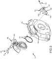
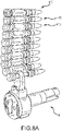
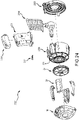
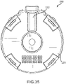
- FIG. 1 it illustrates an exploded view of an exemplary drum magazine assembly 1 according to one embodiment.
- the exemplary drum magazine assembly 1 has a front cover assembly 10, a wheel 20, a drum body and spring assembly 30, a follower assembly 40, a rear cover 50, and retainer clips 60.
- the terms “front” and “distal” shall refer to a side or direction associated with a direction of intended fire; for example, in FIG. 1 , the front or distal side is towards the left.
- distal shall refer to a section of the component that is distant from the pivot point
- proximal shall refer to a section of the component approaching the pivot point.
- the teeth 201 are at a distal region of the wheel 20.
- back, “rear”, or “proximal” shall be associated with the intended bracing of a weapon, or the intended pivot point of a pivoting or rotating component.
- the term "exemplary” is used herein to mean “serving as an example, instance, or illustration.” Any embodiment described herein as “exemplary” is not necessarily to be construed as preferred or advantageous over other embodiments.
- the term “cartridge” should be understood to include generally ammunition that is magazine-fed, such as, for example, shotgun cartridges, grenade cartridges, and any other ammunition packaging a bullet or shot, a propellant substance and a primer within a case that is made to fit within a firing chamber of a firearm.
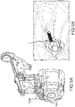
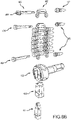
- FIG. 1 and FIG. 2 which illustrate an exploded view and a perspective view, respectively, of a drum magazine assembly 1 a feed tower assembly 70 may be coupled to a drum body 302, and retained by a front cover 10.
- a rear cover 50 may be connected to the drum body assembly 30 and retained thereon by retaining clips 60.
- the drum magazine assembly 1 may be configured to hold 50 to 100 or more cartridges, such as in a single-stack design having a generally spiraled stack configuration inside the drum body 302. It should also be understood that the maximum loading capacity of the drum magazine assembly 1 is dependent on the caliber of ammunition used. For larger sized cartridges, for example, and without limitation, the drum magazine assembly 1 may be configured to hold as little as 35 cartridges at maximum loading capacity. In still other embodiments, the drum magazine assembly 1 may be configured to hold as little as 10 cartridges at maximum loading capacity. These capacities should be considered exemplary only.
- the drum magazine 1 may have a viewing window on the rear cover 50, with the viewing window extending substantially from a central portion of the rear cover 50 to a distal portion of the rear cover 50.
- the viewing window need not necessarily include a transparent cover; instead, the viewing window may comprise an elongated opening in the rear cover 50, or a series of openings which may or may not be covered with a transparent material and/or semi-transparent material.
- the rear cover 50 may be manufactured of a transparent or semi-transparent material.
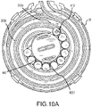
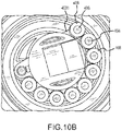
- the terms “spiral” and “generally spiraled”, when used in reference to the stack configuration and/or the winding of the spiral track 303 illustrated in FIG. 10A are not meant to limit the description to a perfect or near-perfect spiral, or curve that winds around a fixed point at a continuously increasing or decreasing distance.
- the terms “spiral” and “generally spiraled” may be used to reference a configuration wherein the track 303 winds around a fixed point at a discontinuously changing distance, as illustrated in FIG. 10A . More specifically, portions 303a of the track 303 may be approximately in a straight line, while other portions 303b of the track 303 may more closely approximate a concentric circular winding.
- the various components of the drum magazine assembly 1 may be manufactured of suitable polymeric materials, high-strength synthetic materials, composites, ceramics, various metals including aluminum, stainless steel or alloys, or any other material suitable for the intended use with a firearm, and the components may have one or more surface finishes suitable to minimizing friction between certain moving parts, which will be discussed in further detail below, as well as an external profile suitable for handling.
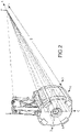
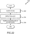
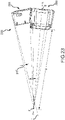
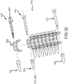
- the drum magazine assembly 1 is designed such that a focal point of each cartridge substantially converges at a single point P at a distance D from the drum magazine assembly 1.
- substantial convergence should be understood to mean bringing the convergence within reasonable manufacturing tolerances. This substantial convergence allows for more optimal stacking of the cartridges, thus distributing forces across each cartridge case, and improving stack consistency and feeding. Moreover, the substantial convergence allows the cartridges to pass more smoothly through the drum magazine assembly 1 to the loading chamber as compared to a drum assembly not having the substantially converging focal point.
- the point P is defined by the conical apex of the multiple cartridges, or the length of taper of each cartridge case; that is, the distance D would be greater for cartridges designed with a slight taper than for cartridges designed with a more extreme taper.
- FIGS. 1-2 Also shown in FIGS. 1-2 is a first pivot axis A of an embodiment. As will be more apparent with brief reference to FIG. 8B and FIG. 1 , axis A is approximately defined by the spindle 403 of the follower assembly 40. The wheel 20 and arm 106 may also be configured to pivot about axis A.
- the front cover assembly 10 may be included to provide an advancing mechanism, which may include a lever 104, an arm 106, and a pawl 108 assembly configured to enable a user to retract a spring 301 while loading cartridges.
- an advancing mechanism or process may include the components and steps required to extend or rotate a lever 104 to increase a moment arm, turn a wheel 20, load cartridges, and release a lever 104 while returning. Rotating the lever 104 also adds the advantage that one can hold the lever 104, and thus reduce spring pressure, while loading cartridges.
- the arm return spring 110 may be provided to ensure the arm 106 is returned to and/or remains biased towards a starting position after each advancing motion.
- the lever lock 1043 may be configured to prevent the lever 104 from being opened when the drum magazine assembly 1 is installed in a weapon. This lever lock 1043 prevents accidental activation of the lever 104, especially when the magazine 1 is being used as a weapon-stabilizing support, or is being used in an environment in which branches, debris, load bearing equipment, or the operator could inadvertently entangle or push on the lever 104.
- the follower assembly 40 may retract enough to allow two or more cartridges to be loaded. Particularly when the follower assembly 40 is near a fully extended position, more cartridges may be loaded after a single advancing motion. When the follower assembly 40 is or moves closer to a fully retracted position, fewer cartridges may be inserted. Upon release of the lever 104, the follower assembly 40 resumes the bias towards the feed lip.
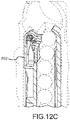
- FIG. 12B it can be seen that, as cartridges are inserted, overcoming the opposing forces of the cartridge gate spring 704, the gate tab 7051 is deflected out of the way, to allow the cartridges to be inserted.
- the follower assembly 40 maintains the leading follower dummy/roller 406, 407 biased towards the feed lip 7011 of the feed tower 701.
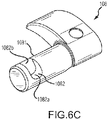
- the feed mechanism 801 may also be a magazine, such as a stick type magazine assembly.
- the feed mechanism 801 embodied as a stick type magazine may be particularly suitable for very high capacity magazines, which, particularly at maximum loading capacity, begin to exhibit similar problems with nose-diving as seen in drum magazines.
- the feed mechanism 801 may be configured to house cartridges having a caliber of 7 millimeters, or greater, or less, such as 4.7 millimeters.
- the feed mechanism 801 may be configured to house cartridges having a caliber of 8.5 millimeters or greater.
- the feed mechanism 801 may be configured to house cartridges having a caliber of 12.7 millimeters or greater.
- the feed mechanism 801 may be configured to house cartridges having a caliber of 25 millimeters or greater.
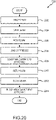
- FIG. 20 a method 2000 of loading a magazine is illustrated.
- the method 2000 includes bracing a drum magazine 2002, opening a lever 2004, rotating an arm 2006, loading at least one cartridge 2008, returning the arm 2010, and closing the lever 2012.
- opening a lever 2004 need not necessarily include rotating a lever about an axis, such as described with reference to FIGS. 1-19 ; instead, as just one example, opening a lever 2004 may include causing a lever to extend relative to a central pivot axis, to increase an advancing moment arm, such as by using a telescoping feature and motion.
- Rotating the arm 2006 may include applying a force on the lever to cause the arm to rotate about a central axis.
- Loading at least one cartridge 2008 includes placing at least one cartridge in the magazine while the arm is held in an advanced or rotated state.
- Loading at least one cartridge 2008 may include loading a plurality of cartridges into a magazine assembly for a weapon, which may be a drum magazine assembly 1 such as that described with reference to FIGS. 1-17 , such that a focal point of each of the one or more cartridges substantially converges a point P at a distance D from the magazine assembly, regardless of where in the magazine assembly each of the cartridges is located.
- Loading at least one cartridge 2008 may include causing a magazine follower, which may be configured like the follower assembly 40 previously described with reference to FIG.
- the method 2000 may also include holding the arm in an advanced or rotated state relative to a start position by applying a force to a lever using a hand, the hand being the same hand used for bracing the drum magazine.
- Closing the lever 2012 includes allowing a biasing force to rotate the lever relative to the arm. Closing the lever 2012 may also include causing a pawl, operatively coupled to the lever, to disengage from a wheel.
- the method 2000 may optionally include blocking arm advancement 2014.
- Blocking arm advancement 2014 may include causing an advancement lock feature to prevent advancement of the arm if the lever is not rotated.
- Blocking arm advancement 2014 may be achieved using, for example, the advancement lock feature having a groove 1042 and lever lock 1043 previously described in this document with reference to FIG. 3 .
- the method 2000 may also include constraining a cartridge 2009.
- Constraining a cartridge 2009 includes preventing the bullet tip and/or a majority of the back end of the cartridge from sliding against any portion of the magazine assembly.
- Constraining a cartridge 2009 may be accomplished using a spiral track 303 configured like the one previously discussed with reference to FIG. 7 .
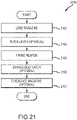
- Blocking a lever 2104 includes causing the weapon to block the lever at a lever lock on the lever, thereby preventing the lever from being opened. Blocking a lever 2104 may be achieved using, for example, a lever 104 as described with reference to any one of FIGS. 1-19 .
- the method 2100 may also include engaging a bolt catch 2108.
- Engaging a bolt catch 2108 includes causing a bolt catch engagement feature, such as a tab 4061 on a leading portion of a follower assembly, to engage a bolt catch on a weapon after a final cartridge is fired, thus simplifying loading of a subsequent loaded magazine.
- Engaging a bolt catch 2108 may be achieved using components similar to those discussed with reference to FIGS. 8 and 14A-B .
- the method 2100 may further include disengaging the magazine 2110 from a weapon, and may be achieved using any means, components, or actions known to those skilled in the art.
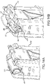
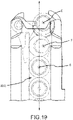
- Positioning a dummy cartridge or a second cartridge 2206 includes positioning one of a first dummy cartridge and another of the one or more cartridges such that a central axis of the one of a first dummy cartridge and another of the one or more cartridges does not converge with the focal axis and is not parallel to the focal axis. More specifically, positioning 2206 may include positioning a dummy cartridge or a second cartridge such that the central axis does not converge with the focal axis E as illustrated in FIGS. 18-19 .
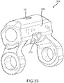
- the angle ⁇ may be about 5 degrees less than an angle suitable for causing a focal axis of the leading cartridge to intersect with a focal point of cartridges in the drum assembly 2330 (compare FIG. 2 with FIG. 23 ). That is, an angle ⁇ between a line from the leading cartridge to the point P and the focal axis F may be about 5 degrees in some embodiments.
- angle ⁇ will vary according to the number and type of cartridges being housed, as well as other design choices, including, without limitation, the cartridge type being housed, the center of mass of the cartridge(s), friction in the design of the assembly, and the capacity of the magazine.
- the angle ⁇ is selected in some embodiments so as to balance the pressure exerted by the spring 301 on the leading cartridge to prevent undesirable diving of the leading cartridge prior to or as it is being fed to the weapon (see also FIGS. 24-25 ).
- a number of related factors should be considered to prevent undesirable diving of the leading cartridge, including overall weakened spring pressure due to friction, spring pressure that is improperly balanced on the leading cartridge, causing the leading cartridge to tend to spin about the pitch axis (see FIG. 12A ) of the leading cartridge, the angle ⁇ between the tower assembly 2370 and the drum assembly 2330, various tolerance stack-up considerations, and/or a deformed or deformable cartridge casing.
- an angled tower assembly 2370 is provided to compensate for a nearly or generally straight feed tower as illustrated in FIG. 23 , necessitated by the geometry of the firearm. That is, since the feed tower assembly 2370 diverges from the ideal focal point geometry, the assembly 2370 causes pressure on the rear of the cartridge(s) to increase, resulting in a nose-down presentation of the cartridge(s). Angling the tower assembly 2370 forward (compare FIG. 23 with FIG. 2 ) rebalances the cartridge pressure and forces the cartridge(s) to present properly.
- an angle ⁇ of between about 0 degrees and 15 degrees in some embodiments, or between about 0 degrees and about 7 degrees, between about 5 degrees and about 7 degrees, or 7 degrees may be suitable for ensuring enough force is placed on the front portion of the leading cartridge to prevent diving without inadvertently causing the leading cartridge to deform, thereby maximizing the feeding reliability.
- angle ⁇ Other factors that affect the selection of the angle ⁇ include is the limitations of the firearm itself, and the geometry into which the firearm forces the magazine 2300. That is, angling the tower assembly 2300 is, in some embodiments, a solution for correcting divergent geometry, and may be a primary design factor over other design factors such as the number and type of cartridges, friction, deformation of cartridges, etc.
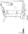
- the drum magazine assembly 2300 may have some features that are substantially identical to the assembly 1, such as a cover 10, retaining clips 60, a wheel 20, and some features that are similar to the assembly 1, such as a drum assembly 2330, a follower assembly 2340, a rear cover assembly 2350, a feed tower assembly 2370 with a fastener 2371 such as a screw, and a protective cap 2390. It should be understood that, where a description of particular features or functions in the drum magazine assembly 2300 is omitted in this disclosure, the features or functions of the assembly 1 should be understood as applicable or suitable.
- the retaining clips 60 may be configured to allow for disassembly by a user using a basic tool that is typically expected to be available to a user in the field.
- the basic tool may in some embodiments be a flathead screwdriver, a knife, or, in some cases, a cartridge tip itself.
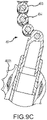
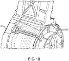
- the follower assembly 2340 may be provided with a spindle 2343 (see FIG. 25 ) that does not have teeth for engaging follower links (compare to spindle teeth 4031 in FIG. 9C ), to decrease the overall amount of friction in the system.
- a bushing 2303 made from or coated by a suitably strong and lubricious material may be provided between the drum body 2302 and the spindle 2343 so as to further reduce friction without adversely impacting performance.
- the bushing 2303 can be made from or coated by a material that is more lubricious than other materials in the system 2300.
- the drum body 2302, spindle 2343, and/or other components may be made of a less lubricious but more durable polymer and/or a reinforced polymer, while the bushing 2303 may be made of a more lubricious material, molybdenum disulfide-filled polymer (MDS) nylon, Acetal, PTFE, etc., to provide overall enhanced strength to the system 2300 while selectively reducing friction in specific areas and/or maintaining impact resistance.
- MDS molybdenum disulfide-filled polymer
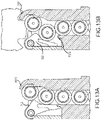
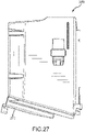
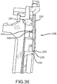
- a feed tower assembly 2370 is provided.
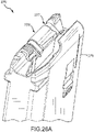
- the feed tower assembly 2370 is similar to the feed tower assembly 70 or feed mechanism 801 previously disclosed herein, and includes a drum assembly interface 2372 and a feed tower body 2379 (see FIG. 26A ) for guiding cartridges from the drum assembly 2330 (see FIG. 24 ) towards a feed position to the firearm, as well a cartridge guide 2377 and a cartridge gate 2378 that function substantially as described with reference to the feed tower assembly 70.
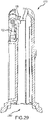
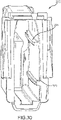
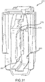
- the feed tower assembly 2370 may exclude a timed cartridge alignment. That is, the feed tower body 2379 may be configured to guide the cartridges in a linear or straight path through the feed tower body 2379, without the jog seen in feed tower 701 or feed mechanism 801. Said another way, the feed tower body 2379 may be configured to maintain the focal axes of cartridges therein substantially in a single plane when the cartridges are between the tower entry 2380 and the tower exit 2381 (see FIG. 29 ), using fore and aft guides 2376, 2375 and fore and aft rails 2374, 237, most clearly seen in FIGS. 30-31 (contrast with the align element 8016 and diverge element 8017 illustrated in FIG. 18 ).
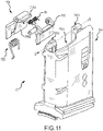
- the cartridge guide 702 and gate 705 can be embodied in any number of shapes or forms.
- the cartridge guide 702 may be configured to shift a leading cartridge (not illustrated towards a side of the feed tower assembly 2370 into a feed-ready position.
- the gate 705 may be configured to perform this shifting function.
- the gate 705 and guide 702 may be configured to perform this function together and/or each of the gate 705 and guide 702 may be configured to perform a portion of this shifting function.
- these embodiments of the gate 705 and guide 702 may be included in the feed tower assembly 70 illustrated in FIG. 11 .
- aspects of the feed tower 2370 can be applied to box magazines as well as the herein described drum magazines.
- a feed mechanism such as a box magazine for a firearm may be provided, having the exit features and guides or rails 2376, 2375, 2374, 2373 as illustrated with the feed tower assembly 2370, without an interface 2372 to a drum assembly.
- the feed tower assembly 2370 may include any floor (not illustrated) known in the art.
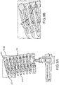
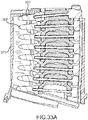
- the follower assembly 3200 comprises a plurality of dummy cartridges, each comprised of a dummy roller 3204 or leading dummy roller 3206 and a follower dummy 3205 or leading follower dummy 3207.
- a plurality of links 3208 may couple the dummy cartridges together, as illustrated in FIG. 32 , and to the spindle 2343, as illustrated in FIG. 25 .
- the follower assembly 3200 functions in a manner substantially similar to the follower assembly 40 illustrated in FIG. 8A .
- the follower assembly 3200 may have one or a plurality of dummy cartridges that freely rotate relative to an associated link, such as by spinning about a roll axis of the respective dummy cartridge comprising the dummy roller 3204 and dummy 3205 (see FIG. 32 ).
- the follower assembly 3200 illustrated in FIG. 32 may include a leading dummy roller 3206 that does not spin relative to the leading link 3208 to provide a functioning bolt catch engagement feature 3261.
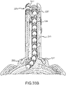
- the links 3208 may be configured to further reduce friction and/or contact with the drum body 2302 (see also FIG. 33B ) as compared to the links 408 illustrated in FIG. 8B .
- the links 3208 may include a recessed surface 3209 configured to prevent friction between the links 3208 and the drum body 2302 or feed tower body 2379. As illustrated in FIG. 33 , the links 3208 may also have a lower recess 3210 and/or an upper recess 3211 for providing clearance for other features in the interior of the magazine 2300.
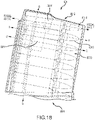
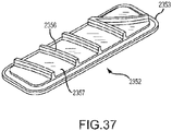
- the rear cover assembly 2350 may include a rear cover 2351 and a clear window 2352 to provide a user with a visual indication of the number of cartridges remaining in the drum magazine assembly 2300.
- the window 2352 may include a flange 2353 for engaging a recess 2354 in the rear cover 2351. See FIGS. 36-37 for various details of the window 2352 and the rear cover 2351.
- the rear cover 2351 may be over-molded on the window 2352 or a portion of the window 2352 (e.g., over-molded on the flange 2353) to provide a smooth track surface on which cartridges or dummy cartridges may travel. That is, as illustrated in FIG. 36 , the rear cover 2351 may have a track ridge 2355 that functions substantially as the track ridge 501, illustrated in FIGS. 7A-7C .
- the track ridge 2355 may be over-molded onto one or more protrusions 2356 in a viewing window 2352 and/or shaped to engage the protrusion(s) 2356 while maintaining a smooth path of travel for a cartridge or follower in the assembly 2300 (see FIG. 24 ).
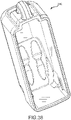
- a protective cap 2390 may be provided to protect the exit portion or feed end of the feed tower assembly 2370 during transportation or storage of the drum magazine assembly 2300 or feed tower assembly 2370 (see e.g. FIG. 24 ).
- the method 4000 includes providing 4002 a window, such as the viewing window 2352 illustrated in FIG. 37 , having at least one flange 2353 and at least one protrusion 2356.
- the flange 2353 may be a protrusion or ridge substantially parallel to a viewing pane 2357, and may provide enough surface area to which a recess 2354 (see e.g., FIG. 36 ) in the rear cover 2352 may reliably adhere.
- the protrusion 2356 may extend substantially perpendicularly from the viewing pane 2357.
- the method 4000 further includes molding 4004 a rear cover body onto the window in a configuration such that the protrusion extends towards an interior region of the rear cover body in an over-molding process, to provide a rear cover assembly, which may be substantially as illustrated in FIGS. 34-36 .
- the rear cover body may be made of a polymer, or a reinforced polymer, and/or the viewing window may be made of a clear polymer.
Landscapes
- Engineering & Computer Science (AREA)
- General Engineering & Computer Science (AREA)
- Portable Nailing Machines And Staplers (AREA)
- Automatic Tape Cassette Changers (AREA)
- Packaging Of Annular Or Rod-Shaped Articles, Wearing Apparel, Cassettes, Or The Like (AREA)
- Toys (AREA)
- Tyre Moulding (AREA)
Claims (14)
- Magazinanordnung (1) für eine Feuerwaffe, umfassend:ein Magazingehäuse, das eine Spur (303) definiert; undeine Folgeranordnung (40);wobei das Magazingehäuse einen proximalen Anschlagmechanismus mit proximalen äußeren und inneren Anschlagflächen (305a, 305b) auf gegenüberliegenden Seiten der Spur (303) und einer Spurkante (501) umfasst, wobei der proximale Anschlagmechanismus so konfiguriert ist, dass er eine Patrone (410) berührt und einschränkt, wenn die Patrone (410) innerhalb der Magazinanordnung (1) bewegt wird, so dass ein Großteil eines proximalen Oberflächenbereichs der Patrone (410) das Magazingehäuse nicht berührt, und so konfiguriert ist, dass sie die Patrone (410) an einem Brennpunkt (P) der Patrone festhält, so dass ein Brennpunkt (P) jeder Patrone, unabhängig davon, wo die Patronen in dem Magazingehäuse angeordnet sind, im Wesentlichen an einem einzigen Punkt (P) in einem Abstand (D) von der Magazinanordnung konvergiert, und wobei das Magazingehäuse so konfiguriert ist, dass es die Patrone festhält, wenn die Patrone in der Magazinanordnung bewegt wird, so dass eine distale Spitze der Patrone (410) das Magazingehäuse nicht berührt.
- Magazinanordnung (1) nach Anspruch 1, wobei:
das Magazin ein Trommelmagazin ist; und das Magazingehäuse einen Trommelkörper (302) und eine hintere Abdeckung (50) umfasst. - Magazinanordnung (1) nach Anspruch 2, wobei:
der Trommelkörper (302) und die hintere Abdeckung (50) miteinander gekoppelt sind, um die Spur (303) dazwischen zu definieren und um eine Kassette (410) dazwischen zu halten. - Magazinanordnung (1) nach Anspruch 1, die ferner Folgendes umfasst:
die Spurleiste (501), die an einer proximalen Fläche der Kassette (410) anliegt. - Magazinanordnung (1) nach Anspruch 4, wobei:
die Führungsrippe (501) so konfiguriert ist, dass sie an einer Minderheit eines proximalen Oberflächenbereichs der Patrone (410) anliegt. - Magazinanordnung (1) nach Anspruch 1, wobei:
das Magazingehäuse einen distalen Anschlag (304) umfasst, der so konfiguriert ist, dass er an einem Gehäuse der Patrone (410) anliegt, so dass die distale Spitze der Patrone (410) das Magazingehäuse nicht berührt. - Magazinanordnung (1) nach Anspruch 6, wobei:
der distale Anschlag (304) so konfiguriert ist, dass er verhindert, dass eine Spitze der Patrone (410) das Magazingehäuse berührt. - Magazinanordnung (1) nach Anspruch 7, wobei:
das distale Widerlager so konfiguriert ist, dass es einen Brennpunkt (P) der Patrone (410) einschränkt. - Magazinanordnung (1) nach Anspruch 1, die ferner umfasst ein Sichtfenster.
- Magazinanordnung (1) nach Anspruch 9, die ferner umfasst
mindestens eine transparente Abdeckung über dem Sichtfenster oder eine halbtransparente Abdeckung über dem Sichtfenster. - Magazinanordnung (1) nach Anspruch 1, wobei:
mindestens ein Teil des Magazingehäuses mindestens eines von einem transparenten Material und einem halbtransparenten Material umfasst. - Magazinanordnung (1) nach Anspruch 1, wobei:
die Spur (303) eine Spiralspur (303) ist, wobei sich die Spiralspur (303) um eine zentrale Achse windet mit(a) einer kontinuierlich ansteigenden Geschwindigkeit, oder(b) einer diskontinuierlich ansteigenden Rate, wobei die Spiralbahn optional Abschnitte aufweist, die sich mit einem konstanten Radius um die zentrale Achse winden. - Verfahren zum Einspannen einer Patrone (410) in einer Magazinanordnung (1) für eine Feuerwaffe, das die folgenden Schritte umfasst:Bereitstellen eines Magazingehäuses, das eine Spur (303) definiert;Bereitstellen einer Folger-Baugruppe (40);Einspannen der Patrone (410) mittels eines proximalen Anschlagmechanismus mit einer Spurkante (501) und proximalen äußeren und inneren Anschlagflächen (305a, 305b) des Magazingehäuses auf gegenüberliegenden Seiten der Spur (303), wobei der proximale Anschlagmechanismus die Patrone (410) berührt und an einem Brennpunkt (P) einspannt, wenn die Patrone (410) innerhalb der Magazinanordnung (1) bewegt wird, so dass:ein Großteil eines proximalen Oberflächenbereichs der Patrone das Magazingehäuse nicht berührt;ein Brennpunkt (P) jeder Patrone, unabhängig davon, wo die Patronen in dem Magazingehäuse angeordnet sind, im Wesentlichen in einem einzigen Punkt (P) in einem Abstand (D) von der Magazinanordnung konvergiert; undEinspannen der Patrone, so dass eine distale Spitze der Patrone (410) das Magazingehäuse nicht berührt.
- Verfahren nach Anspruch 13, das außerdem einen oder mehrere der folgenden Schritte umfasst:Einspannen der Patrone (410) in der Spur;Bewirken, dass der Spurrücken (501) an einer proximalen Fläche der Patrone (410) anliegt;Unterstützen einer Minderheit des proximalen Oberflächenbereichs der Patrone (410); undStützen einer Minderheit des proximalen Oberflächenbereichs der Patrone (410); und Anstoßen eines distalen Abschnitts eines Gehäuses der Patrone (410), so dass die distale Spitze der Patrone (410) nicht das Magazingehäuse berührt.
Priority Applications (2)
| Application Number | Priority Date | Filing Date | Title |
|---|---|---|---|
| EP24152519.5A EP4332493A3 (de) | 2014-10-14 | 2015-10-13 | Trommelmagazinanordnung und verfahren |
| EP22194032.3A EP4141374B1 (de) | 2014-10-14 | 2015-10-13 | Trommelmagazinanordnung und verfahren |
Applications Claiming Priority (3)
| Application Number | Priority Date | Filing Date | Title |
|---|---|---|---|
| US201462063546P | 2014-10-14 | 2014-10-14 | |
| PCT/US2015/055361 WO2016061122A2 (en) | 2014-10-14 | 2015-10-13 | Drum magazine assembly and methods |
| EP15850706.1A EP3105526B1 (de) | 2014-10-14 | 2015-10-13 | Trommelmagazinanordnung und verfahren |
Related Parent Applications (2)
| Application Number | Title | Priority Date | Filing Date |
|---|---|---|---|
| EP15850706.1A Division EP3105526B1 (de) | 2014-10-14 | 2015-10-13 | Trommelmagazinanordnung und verfahren |
| EP15850706.1A Division-Into EP3105526B1 (de) | 2014-10-14 | 2015-10-13 | Trommelmagazinanordnung und verfahren |
Related Child Applications (2)
| Application Number | Title | Priority Date | Filing Date |
|---|---|---|---|
| EP22194032.3A Division EP4141374B1 (de) | 2014-10-14 | 2015-10-13 | Trommelmagazinanordnung und verfahren |
| EP24152519.5A Division EP4332493A3 (de) | 2014-10-14 | 2015-10-13 | Trommelmagazinanordnung und verfahren |
Publications (2)
| Publication Number | Publication Date |
|---|---|
| EP3567334A1 EP3567334A1 (de) | 2019-11-13 |
| EP3567334B1 true EP3567334B1 (de) | 2022-09-07 |
Family
ID=55655214
Family Applications (4)
| Application Number | Title | Priority Date | Filing Date |
|---|---|---|---|
| EP15850706.1A Active EP3105526B1 (de) | 2014-10-14 | 2015-10-13 | Trommelmagazinanordnung und verfahren |
| EP19182510.8A Active EP3567334B1 (de) | 2014-10-14 | 2015-10-13 | Trommelmagazinanordnung und verfahren |
| EP22194032.3A Active EP4141374B1 (de) | 2014-10-14 | 2015-10-13 | Trommelmagazinanordnung und verfahren |
| EP24152519.5A Pending EP4332493A3 (de) | 2014-10-14 | 2015-10-13 | Trommelmagazinanordnung und verfahren |
Family Applications Before (1)
| Application Number | Title | Priority Date | Filing Date |
|---|---|---|---|
| EP15850706.1A Active EP3105526B1 (de) | 2014-10-14 | 2015-10-13 | Trommelmagazinanordnung und verfahren |
Family Applications After (2)
| Application Number | Title | Priority Date | Filing Date |
|---|---|---|---|
| EP22194032.3A Active EP4141374B1 (de) | 2014-10-14 | 2015-10-13 | Trommelmagazinanordnung und verfahren |
| EP24152519.5A Pending EP4332493A3 (de) | 2014-10-14 | 2015-10-13 | Trommelmagazinanordnung und verfahren |
Country Status (6)
| Country | Link |
|---|---|
| US (7) | US9528784B2 (de) |
| EP (4) | EP3105526B1 (de) |
| KR (2) | KR101922823B1 (de) |
| CN (2) | CN108007262B (de) |
| RU (1) | RU2708128C1 (de) |
| WO (1) | WO2016061122A2 (de) |
Families Citing this family (25)
| Publication number | Priority date | Publication date | Assignee | Title |
|---|---|---|---|---|
| EP3105526B1 (de) | 2014-10-14 | 2019-08-21 | Magpul Industries Corp. | Trommelmagazinanordnung und verfahren |
| US10378841B2 (en) * | 2015-04-23 | 2019-08-13 | Benjamin Jeffrey Vickers | Drum magazine bolt catch actuator |
| US10228202B2 (en) | 2016-04-22 | 2019-03-12 | Ra Brands, L.L.C. | Magazine with spacers for accommodating multiple caliber, size and/or length rounds |
| US10317153B2 (en) | 2016-07-11 | 2019-06-11 | Sagi Faifer | Apparatus and method for increasing capacity of an ammunition magazine |
| US10060691B2 (en) * | 2016-08-27 | 2018-08-28 | Joshua M. Kunz | Firearm magazine follower with enhanced stability and debris clearing features |
| KR101942186B1 (ko) * | 2017-05-31 | 2019-03-18 | 배교환 | 원통형 탄창 |
| US10345064B2 (en) | 2017-10-19 | 2019-07-09 | Smith & Wesson Corp. | Rotary magazine and bolt catch |
| US11067351B2 (en) * | 2018-04-09 | 2021-07-20 | James Matthew Underwood | Ratcheting magazine assembly |
| IL258680A (en) | 2018-04-12 | 2018-05-31 | Atias Eliran | Ammunition storage and feed system |
| US11236962B2 (en) | 2019-01-29 | 2022-02-01 | Mcp Ip, Llc | Crossbow arrow rest |
| USD892962S1 (en) * | 2019-03-04 | 2020-08-11 | Magpul Industries Corp. | Drum magazine |
| KR102659778B1 (ko) * | 2019-03-14 | 2024-04-22 | 맥펄 인더스트리즈 코프. | 탄창용 볼트 잠금 후면 시스템 |
| KR102274354B1 (ko) * | 2019-06-28 | 2021-07-06 | 맥펄 인더스트리즈 코프. | 슬라이드 잠금-백 종동자 어셈블리 |
| RU2725113C1 (ru) * | 2020-01-14 | 2020-06-29 | Максим Сергеевич Турлаков | Винтовка турлакова n 7 (галина) |
| KR102269704B1 (ko) * | 2020-06-09 | 2021-06-28 | 영 케이 리 | 드럼식 탄창용 탄알 안내장치 |
| US12188736B2 (en) | 2020-10-21 | 2025-01-07 | Tac-Clamp, LLC | Firearm positioning systems and methods |
| US11656050B2 (en) | 2020-10-21 | 2023-05-23 | Tac-Clamp, LLC | Firearm positioning systems and methods |
| EP4348152B1 (de) * | 2021-07-02 | 2025-08-27 | Magpul Industries Corp. | In einem zuführturm montierte blattfedern für magazine |
| US11940241B2 (en) * | 2021-09-14 | 2024-03-26 | Buzz Bee Toys, Inc. | Drum-fed toy projectile launcher with radially stacked projectiles in drum |
| DE102021004782B4 (de) * | 2021-09-22 | 2023-12-28 | Schmeisser Gmbh | Gehäuseabschnitt für ein Patronenmagazin für eine Handfeuerwaffe, Patronenmagazin mit Gehäuseabschnitt, Umrüstsatz, Verfahren zum Umbau eines Patronenmagazins, sowie Verfahren zum Betreiben einer Handfeuerwaffe |
| KR102408544B1 (ko) * | 2021-12-02 | 2022-06-13 | 김승호 | 드럼식 탄창 |
| US12422206B2 (en) * | 2022-12-28 | 2025-09-23 | Akdaş Silah Anonim Şirketi | Ammunition feeding system |
| US12422207B2 (en) * | 2023-06-12 | 2025-09-23 | Eight Holdings LLC | Detachable ammunition magazine |
| US12209837B1 (en) * | 2023-07-26 | 2025-01-28 | Christopher Madden | Automatically ejecting magazine device |
| CN118913016B (zh) * | 2024-07-19 | 2025-11-11 | 南京理工大学 | 一种恒力可靠大容量弹盘 |
Citations (1)
| Publication number | Priority date | Publication date | Assignee | Title |
|---|---|---|---|---|
| US118916A (en) * | 1871-09-12 | Improvement in cartridge-magazines |
Family Cites Families (75)
| Publication number | Priority date | Publication date | Assignee | Title |
|---|---|---|---|---|
| US627850A (en) | 1898-10-13 | 1899-06-27 | Fairbanks Morse & Co | Compression-controller. |
| US681151A (en) | 1901-07-05 | 1901-08-20 | Frank Theodore | Tire for vehicles. |
| US1042837A (en) | 1911-02-09 | 1912-10-29 | Johan Von Benko De Arkosi | Automatic cartridge-magazine for firearms. |
| US1118916A (en) | 1914-08-20 | 1914-12-01 | Us Mfg Company | Oil-burner. |
| US1333498A (en) * | 1916-05-16 | 1920-03-09 | Charles W Lang | Rapid-fire gun |
| US1451339A (en) * | 1918-08-16 | 1923-04-10 | Kottas Arthur | Magazine firearm |
| US1337893A (en) * | 1918-12-30 | 1920-04-20 | Farquhar Moubray Gore | Cartridge-magazine for rifles and machine-guns |
| FR571475A (fr) | 1923-10-04 | 1924-05-17 | Dansk Rekylriffel Syndikat As | Magasin à cartouches en forme de tambour pour mitrailleuses ou autres armes semblables |
| US1747546A (en) * | 1928-01-25 | 1930-02-18 | Janecek Frantisek | Machine gun |
| US1811093A (en) | 1930-03-21 | 1931-06-23 | Chester T Neal | Cartridge clip |
| US2064888A (en) | 1935-06-04 | 1936-12-22 | Fred A Dickinson | Spiral groove rifle magazine |
| US2321720A (en) * | 1941-05-13 | 1943-06-15 | Automatic Appliance Corp | Magazine for firearms |
| GB573211A (en) * | 1941-07-26 | 1945-11-12 | Josef Vesely | Improvements in or relating to magazines for fire arms |
| US2489428A (en) * | 1944-02-21 | 1949-11-29 | United Shoe Machinery Corp | Magazine for machine guns |
| US2448081A (en) | 1944-07-20 | 1948-08-31 | Woodville B Conway | Automatic ammunition feed for firearms |
| US2426517A (en) * | 1944-12-26 | 1947-08-26 | Cullen J Mcwhorter | Gun perforator |
| US3239959A (en) | 1964-03-24 | 1966-03-15 | Sturm Ruger & Co | Removable magazine for repeating gun |
| CH458133A (de) | 1964-04-08 | 1968-06-15 | Bofors Ab | Patronenmagazin an einem Geschütz |
| US3399480A (en) | 1966-08-24 | 1968-09-03 | Harrington & Richardson Inc | Plastic magazine for cartridges for firearms |
| US3507186A (en) | 1967-06-29 | 1970-04-21 | Vyzk Vyvojovy Ustav Vseobe | Magazine for automatic firearms |
| US4005633A (en) * | 1973-11-09 | 1977-02-01 | General Electric Company | Structure for article handling systems |
| DE2427974C3 (de) * | 1974-06-10 | 1978-11-30 | Industrie-Werke Karlsruhe Augsburg Ag, 7500 Karlsruhe | Feuerwaffe, insbesondere kurzbauende Handfeuerwaffe |
| US4138923A (en) | 1977-06-29 | 1979-02-13 | The United States Of America As Represented By The Secretary Of The Army | Drum cartridge - magazine |
| US4332097A (en) | 1979-10-01 | 1982-06-01 | Taylor Jr William J | Drum magazine for automatic pistol or the like |
| US4445418A (en) | 1980-12-11 | 1984-05-01 | Chartered Industries Of Singapore Private Limited | Drum magazine for a gun |
| US4384508A (en) * | 1980-12-11 | 1983-05-24 | Chartered Industries Of Singapore Private Ltd. | Drum magazine for a gun |
| KR810002378Y1 (ko) | 1980-12-16 | 1981-12-18 | 호남전기공업주식회사 | 건전지용 단자 고정판 |
| US4413546A (en) * | 1980-12-17 | 1983-11-08 | Taylor Jr William J | Drum magazine for carbines or the like |
| US4524673A (en) | 1982-09-29 | 1985-06-25 | Western Design Corporation | Gun powered ammunition magazine |
| US4524672A (en) | 1983-04-27 | 1985-06-25 | Walter Balsavage | Magazine and feed mechanism for firearms |
| US4509401A (en) | 1983-12-28 | 1985-04-09 | Wayne H. Coloney Company, Inc. | Portable ammunition handling and loading system |
| FR2579743B1 (fr) | 1985-03-26 | 1987-05-15 | France Etat Armement | Arme automatique a moteur externe |
| US4656623A (en) | 1985-05-03 | 1987-04-07 | American Telephone And Telegraph Company | Agent communication arrangements for telecommunication systems |
| US4632687A (en) | 1985-06-25 | 1986-12-30 | Ppg Industries, Inc. | Method of melting raw materials for glass or the like using solid fuels or fuel-batch mixtures |
| US4658700A (en) * | 1985-07-24 | 1987-04-21 | The Beta Company | Drum magazine |
| US4689907A (en) | 1986-05-14 | 1987-09-01 | Gwinn Jr Mack W | Small arm magazine |
| US4926742A (en) | 1986-10-16 | 1990-05-22 | Poly Technologies, Inc. | Spiral drum magazine with elongated magazine clip and single piece last round follower |
| IT1217017B (it) | 1987-04-14 | 1990-03-14 | Vecchieschi Gastone | Caricatore per armi da fuoco con dispositivo per caricamento rapido |
| DE3721527A1 (de) | 1987-06-30 | 1989-01-19 | Heckler & Koch Gmbh | Magazin mit gurtlosem patronen-zufuehrsystem |
| CN87212106U (zh) * | 1987-08-19 | 1988-07-13 | 国营西南仪器厂 | 5.56毫米120发弹鼓 |
| US5056252A (en) | 1989-07-05 | 1991-10-15 | Velezis George A | Firearm magazine |
| US5111729A (en) * | 1990-10-04 | 1992-05-12 | General Electric Company | Ammunition storage system |
| US5309660A (en) * | 1992-11-16 | 1994-05-10 | Blackamore James D | Cartridge magazine |
| US5502913A (en) | 1994-11-18 | 1996-04-02 | Butler Creek Corporation | Cartridge magazine for firearms having improved retainer |
| US5456153A (en) * | 1994-11-21 | 1995-10-10 | Bentley; James K. | Magazine for pump action shotgun |
| US5561258A (en) * | 1995-10-10 | 1996-10-01 | Bentley; James K. | Magazine for pump action shotgun |
| US5905224A (en) * | 1998-06-18 | 1999-05-18 | Paul William Jordan | Pulley belt magazine |
| US6502495B1 (en) | 2000-10-18 | 2003-01-07 | Joseph Alfred Beary | Rotary magazine for firearm with hold-open lever |
| US7343909B2 (en) | 2004-04-28 | 2008-03-18 | Kee Action Sports I Llc | Mechanical drive assist for active feed paintball loader |
| US7441491B2 (en) * | 2005-11-14 | 2008-10-28 | Annatac Industries, Incorporated | Drum magazine for firearm |
| US8156675B2 (en) | 2007-03-08 | 2012-04-17 | Browning | Firearm magazine |
| US7942091B2 (en) | 2007-05-08 | 2011-05-17 | Winge Michael L | Shotgun drum magazine |
| BE1018257A4 (fr) | 2007-06-05 | 2010-08-03 | Otero Y Alonso Gabriel | Chargeur camembert a haute capacite pour riotgun fait pour le systeme cats et tous les autres fusils. |
| CZ19479U1 (cs) | 2009-02-13 | 2009-03-30 | Adh Agency, S. R. O. | Bubnový zásobník |
| AU2010273587B2 (en) * | 2009-07-13 | 2014-07-10 | The Samuel Roberts Noble Foundation, Inc. | Plants with modified lignin content and methods for production thereof |
| CN101660886A (zh) * | 2009-09-13 | 2010-03-03 | 中北大学 | 无假弹弹鼓 |
| US8347774B2 (en) * | 2009-10-07 | 2013-01-08 | Kevin Wayne Rich | Magazine with cartridge gear |
| US8196327B2 (en) | 2009-10-07 | 2012-06-12 | Kevin Wayne Rich | Modular magazine assembly |
| USD627850S1 (en) | 2009-10-07 | 2010-11-23 | Kevin Wayne Rich | Firearm magazine |
| US8220377B2 (en) | 2009-11-09 | 2012-07-17 | Meninas Inc. | Ammunition feed system for firearm |
| US8448558B2 (en) | 2009-11-09 | 2013-05-28 | Meninas Inc. | Ammunition feed system for firearm |
| DE102010009186B4 (de) | 2010-02-24 | 2014-11-13 | German Sport Guns Gmbh | Magazin für eine Handfeuerwaffe |
| US8387296B2 (en) | 2010-04-08 | 2013-03-05 | 22 Evolution Llc | Drop bolt hold open actuator for use with AR-15/M16 type firearms and incorporating a modified and displaceable follower for engaging a bolt catch mechanism such as in conjunction with rimfire ammunition |
| WO2011155971A1 (en) | 2010-05-24 | 2011-12-15 | Meninas Inc. | Ammunition feed system for firearm |
| CN201837306U (zh) | 2010-10-22 | 2011-05-18 | 黄耀锋 | 一种弹鼓 |
| US8919022B2 (en) | 2010-11-04 | 2014-12-30 | Scott Ryan Chewning | High capacity firearm magazine feed mechanism |
| USD681151S1 (en) | 2012-01-12 | 2013-04-30 | Magpul Industries Corporation | Firearm magazine with window |
| KR101271650B1 (ko) * | 2012-08-31 | 2013-06-11 | 노태종 | 드럼식 탄창 |
| US20140096671A1 (en) * | 2012-10-07 | 2014-04-10 | Kenny Yueqing Jiang | Drum Magazine |
| WO2014120317A2 (en) * | 2012-11-15 | 2014-08-07 | Slide Fire Solutions, Lp | Belted ammunition feeding device |
| US8943727B2 (en) | 2012-12-04 | 2015-02-03 | Okay Industries, Inc. | Magazine for a firearm |
| US8966801B1 (en) | 2014-04-23 | 2015-03-03 | Adaptive Tactical Llc | Modular shotgun box magazine |
| EP3105526B1 (de) * | 2014-10-14 | 2019-08-21 | Magpul Industries Corp. | Trommelmagazinanordnung und verfahren |
| KR101501254B1 (ko) | 2014-10-30 | 2015-03-12 | 주식회사 경창산업 | 드럼식 탄창 |
| CN204478918U (zh) | 2015-02-13 | 2015-07-15 | 刘子杰 | 一种快装霰弹弹鼓 |
-
2015
- 2015-10-13 EP EP15850706.1A patent/EP3105526B1/de active Active
- 2015-10-13 US US14/882,151 patent/US9528784B2/en active Active
- 2015-10-13 KR KR1020177006021A patent/KR101922823B1/ko active Active
- 2015-10-13 WO PCT/US2015/055361 patent/WO2016061122A2/en not_active Ceased
- 2015-10-13 EP EP19182510.8A patent/EP3567334B1/de active Active
- 2015-10-13 RU RU2016129530A patent/RU2708128C1/ru active
- 2015-10-13 KR KR1020167020835A patent/KR101714544B1/ko active Active
- 2015-10-13 EP EP22194032.3A patent/EP4141374B1/de active Active
- 2015-10-13 CN CN201711271837.XA patent/CN108007262B/zh active Active
- 2015-10-13 EP EP24152519.5A patent/EP4332493A3/de active Pending
- 2015-10-13 CN CN201580024249.9A patent/CN106461359B/zh active Active
-
2016
- 2016-11-17 US US15/354,492 patent/US10184741B2/en active Active
-
2018
- 2018-11-27 US US16/200,978 patent/US10677550B2/en active Active
-
2020
- 2020-03-06 US US16/811,835 patent/US11085718B2/en active Active
-
2021
- 2021-07-07 US US17/369,608 patent/US11680763B2/en active Active
-
2023
- 2023-05-04 US US18/143,585 patent/US12140396B2/en active Active
-
2024
- 2024-10-07 US US18/908,365 patent/US20250027734A1/en active Pending
Patent Citations (1)
| Publication number | Priority date | Publication date | Assignee | Title |
|---|---|---|---|---|
| US118916A (en) * | 1871-09-12 | Improvement in cartridge-magazines |
Also Published As
Similar Documents
| Publication | Publication Date | Title |
|---|---|---|
| US12140396B2 (en) | Drum magazine assembly and methods | |
| US20150345882A1 (en) | Compact anti-tilt follower for an ammunition magazine | |
| EP3407002A1 (de) | Pelletladesystem | |
| DE102007034675A1 (de) | Verriegelungselement und Patronenzufuhrmechanismus für eine Waffe | |
| EP3004782B1 (de) | Mini-maschinengewehr mit verbesserter zugangsklappe | |
| EP4235081B1 (de) | Bolzenverriegelungssystem für ein magazin | |
| HK1231954A1 (en) | Drum magazine assembly and methods | |
| HK1252671B (zh) | 弹鼓组件和方法 | |
| HK1231954B (en) | Drum magazine assembly and methods | |
| DE102007034669A1 (de) | Griffeinheit für eine Waffe | |
| DE102007034672A1 (de) | Verschlussbauteil, Verschlussanordnung und Verriegelungseinrichtung für eine Waffe | |
| DE102007034667A1 (de) | Sicherungsanordnung für eine Waffe | |
| HK1223412B (en) | Minigun with improved access door |
Legal Events
| Date | Code | Title | Description |
|---|---|---|---|
| PUAI | Public reference made under article 153(3) epc to a published international application that has entered the european phase |
Free format text: ORIGINAL CODE: 0009012 |
|
| STAA | Information on the status of an ep patent application or granted ep patent |
Free format text: STATUS: THE APPLICATION HAS BEEN PUBLISHED |
|
| AC | Divisional application: reference to earlier application |
Ref document number: 3105526 Country of ref document: EP Kind code of ref document: P |
|
| AK | Designated contracting states |
Kind code of ref document: A1 Designated state(s): AL AT BE BG CH CY CZ DE DK EE ES FI FR GB GR HR HU IE IS IT LI LT LU LV MC MK MT NL NO PL PT RO RS SE SI SK SM TR |
|
| STAA | Information on the status of an ep patent application or granted ep patent |
Free format text: STATUS: REQUEST FOR EXAMINATION WAS MADE |
|
| 17P | Request for examination filed |
Effective date: 20200116 |
|
| RBV | Designated contracting states (corrected) |
Designated state(s): AL AT BE BG CH CY CZ DE DK EE ES FI FR GB GR HR HU IE IS IT LI LT LU LV MC MK MT NL NO PL PT RO RS SE SI SK SM TR |
|
| RIN1 | Information on inventor provided before grant (corrected) |
Inventor name: NAKAYAMA, ERIC Inventor name: NAKAYAMA, BRIAN L. Inventor name: ROBERTS, TIMOTHY ERIC Inventor name: FITZPATRICK, RICHARD M. Inventor name: BENNETT, WILLIAM BRADLEY Inventor name: MAYBERRY, MICHAEL T. |
|
| STAA | Information on the status of an ep patent application or granted ep patent |
Free format text: STATUS: EXAMINATION IS IN PROGRESS |
|
| 17Q | First examination report despatched |
Effective date: 20220506 |
|
| GRAP | Despatch of communication of intention to grant a patent |
Free format text: ORIGINAL CODE: EPIDOSNIGR1 |
|
| STAA | Information on the status of an ep patent application or granted ep patent |
Free format text: STATUS: GRANT OF PATENT IS INTENDED |
|
| INTG | Intention to grant announced |
Effective date: 20220623 |
|
| GRAS | Grant fee paid |
Free format text: ORIGINAL CODE: EPIDOSNIGR3 |
|
| GRAA | (expected) grant |
Free format text: ORIGINAL CODE: 0009210 |
|
| STAA | Information on the status of an ep patent application or granted ep patent |
Free format text: STATUS: THE PATENT HAS BEEN GRANTED |
|
| AC | Divisional application: reference to earlier application |
Ref document number: 3105526 Country of ref document: EP Kind code of ref document: P |
|
| AK | Designated contracting states |
Kind code of ref document: B1 Designated state(s): AL AT BE BG CH CY CZ DE DK EE ES FI FR GB GR HR HU IE IS IT LI LT LU LV MC MK MT NL NO PL PT RO RS SE SI SK SM TR |
|
| REG | Reference to a national code |
Ref country code: GB Ref legal event code: FG4D |
|
| REG | Reference to a national code |
Ref country code: CH Ref legal event code: EP Ref country code: AT Ref legal event code: REF Ref document number: 1517390 Country of ref document: AT Kind code of ref document: T Effective date: 20220915 |
|
| REG | Reference to a national code |
Ref country code: IE Ref legal event code: FG4D |
|
| REG | Reference to a national code |
Ref country code: DE Ref legal event code: R096 Ref document number: 602015080764 Country of ref document: DE |
|
| REG | Reference to a national code |
Ref country code: LT Ref legal event code: MG9D |
|
| REG | Reference to a national code |
Ref country code: NL Ref legal event code: MP Effective date: 20220907 |
|
| PG25 | Lapsed in a contracting state [announced via postgrant information from national office to epo] |
Ref country code: SE Free format text: LAPSE BECAUSE OF FAILURE TO SUBMIT A TRANSLATION OF THE DESCRIPTION OR TO PAY THE FEE WITHIN THE PRESCRIBED TIME-LIMIT Effective date: 20220907 Ref country code: RS Free format text: LAPSE BECAUSE OF FAILURE TO SUBMIT A TRANSLATION OF THE DESCRIPTION OR TO PAY THE FEE WITHIN THE PRESCRIBED TIME-LIMIT Effective date: 20220907 Ref country code: NO Free format text: LAPSE BECAUSE OF FAILURE TO SUBMIT A TRANSLATION OF THE DESCRIPTION OR TO PAY THE FEE WITHIN THE PRESCRIBED TIME-LIMIT Effective date: 20221207 Ref country code: LV Free format text: LAPSE BECAUSE OF FAILURE TO SUBMIT A TRANSLATION OF THE DESCRIPTION OR TO PAY THE FEE WITHIN THE PRESCRIBED TIME-LIMIT Effective date: 20220907 Ref country code: LT Free format text: LAPSE BECAUSE OF FAILURE TO SUBMIT A TRANSLATION OF THE DESCRIPTION OR TO PAY THE FEE WITHIN THE PRESCRIBED TIME-LIMIT Effective date: 20220907 Ref country code: FI Free format text: LAPSE BECAUSE OF FAILURE TO SUBMIT A TRANSLATION OF THE DESCRIPTION OR TO PAY THE FEE WITHIN THE PRESCRIBED TIME-LIMIT Effective date: 20220907 |
|
| REG | Reference to a national code |
Ref country code: AT Ref legal event code: MK05 Ref document number: 1517390 Country of ref document: AT Kind code of ref document: T Effective date: 20220907 |
|
| PG25 | Lapsed in a contracting state [announced via postgrant information from national office to epo] |
Ref country code: HR Free format text: LAPSE BECAUSE OF FAILURE TO SUBMIT A TRANSLATION OF THE DESCRIPTION OR TO PAY THE FEE WITHIN THE PRESCRIBED TIME-LIMIT Effective date: 20220907 Ref country code: GR Free format text: LAPSE BECAUSE OF FAILURE TO SUBMIT A TRANSLATION OF THE DESCRIPTION OR TO PAY THE FEE WITHIN THE PRESCRIBED TIME-LIMIT Effective date: 20221208 |
|
| PG25 | Lapsed in a contracting state [announced via postgrant information from national office to epo] |
Ref country code: SM Free format text: LAPSE BECAUSE OF FAILURE TO SUBMIT A TRANSLATION OF THE DESCRIPTION OR TO PAY THE FEE WITHIN THE PRESCRIBED TIME-LIMIT Effective date: 20220907 Ref country code: RO Free format text: LAPSE BECAUSE OF FAILURE TO SUBMIT A TRANSLATION OF THE DESCRIPTION OR TO PAY THE FEE WITHIN THE PRESCRIBED TIME-LIMIT Effective date: 20220907 Ref country code: PT Free format text: LAPSE BECAUSE OF FAILURE TO SUBMIT A TRANSLATION OF THE DESCRIPTION OR TO PAY THE FEE WITHIN THE PRESCRIBED TIME-LIMIT Effective date: 20230109 Ref country code: ES Free format text: LAPSE BECAUSE OF FAILURE TO SUBMIT A TRANSLATION OF THE DESCRIPTION OR TO PAY THE FEE WITHIN THE PRESCRIBED TIME-LIMIT Effective date: 20220907 Ref country code: AT Free format text: LAPSE BECAUSE OF FAILURE TO SUBMIT A TRANSLATION OF THE DESCRIPTION OR TO PAY THE FEE WITHIN THE PRESCRIBED TIME-LIMIT Effective date: 20220907 |
|
| PG25 | Lapsed in a contracting state [announced via postgrant information from national office to epo] |
Ref country code: SK Free format text: LAPSE BECAUSE OF FAILURE TO SUBMIT A TRANSLATION OF THE DESCRIPTION OR TO PAY THE FEE WITHIN THE PRESCRIBED TIME-LIMIT Effective date: 20220907 Ref country code: PL Free format text: LAPSE BECAUSE OF FAILURE TO SUBMIT A TRANSLATION OF THE DESCRIPTION OR TO PAY THE FEE WITHIN THE PRESCRIBED TIME-LIMIT Effective date: 20220907 Ref country code: IS Free format text: LAPSE BECAUSE OF FAILURE TO SUBMIT A TRANSLATION OF THE DESCRIPTION OR TO PAY THE FEE WITHIN THE PRESCRIBED TIME-LIMIT Effective date: 20230107 Ref country code: EE Free format text: LAPSE BECAUSE OF FAILURE TO SUBMIT A TRANSLATION OF THE DESCRIPTION OR TO PAY THE FEE WITHIN THE PRESCRIBED TIME-LIMIT Effective date: 20220907 |
|
| REG | Reference to a national code |
Ref country code: DE Ref legal event code: R097 Ref document number: 602015080764 Country of ref document: DE |
|
| PG25 | Lapsed in a contracting state [announced via postgrant information from national office to epo] |
Ref country code: NL Free format text: LAPSE BECAUSE OF FAILURE TO SUBMIT A TRANSLATION OF THE DESCRIPTION OR TO PAY THE FEE WITHIN THE PRESCRIBED TIME-LIMIT Effective date: 20220907 Ref country code: MC Free format text: LAPSE BECAUSE OF FAILURE TO SUBMIT A TRANSLATION OF THE DESCRIPTION OR TO PAY THE FEE WITHIN THE PRESCRIBED TIME-LIMIT Effective date: 20220907 Ref country code: LU Free format text: LAPSE BECAUSE OF NON-PAYMENT OF DUE FEES Effective date: 20221013 Ref country code: AL Free format text: LAPSE BECAUSE OF FAILURE TO SUBMIT A TRANSLATION OF THE DESCRIPTION OR TO PAY THE FEE WITHIN THE PRESCRIBED TIME-LIMIT Effective date: 20220907 |
|
| PLBE | No opposition filed within time limit |
Free format text: ORIGINAL CODE: 0009261 |
|
| STAA | Information on the status of an ep patent application or granted ep patent |
Free format text: STATUS: NO OPPOSITION FILED WITHIN TIME LIMIT |
|
| PG25 | Lapsed in a contracting state [announced via postgrant information from national office to epo] |
Ref country code: DK Free format text: LAPSE BECAUSE OF FAILURE TO SUBMIT A TRANSLATION OF THE DESCRIPTION OR TO PAY THE FEE WITHIN THE PRESCRIBED TIME-LIMIT Effective date: 20220907 |
|
| 26N | No opposition filed |
Effective date: 20230608 |
|
| GBPC | Gb: european patent ceased through non-payment of renewal fee |
Effective date: 20221207 |
|
| PG25 | Lapsed in a contracting state [announced via postgrant information from national office to epo] |
Ref country code: SI Free format text: LAPSE BECAUSE OF FAILURE TO SUBMIT A TRANSLATION OF THE DESCRIPTION OR TO PAY THE FEE WITHIN THE PRESCRIBED TIME-LIMIT Effective date: 20220907 |
|
| PG25 | Lapsed in a contracting state [announced via postgrant information from national office to epo] |
Ref country code: IE Free format text: LAPSE BECAUSE OF NON-PAYMENT OF DUE FEES Effective date: 20221013 Ref country code: GB Free format text: LAPSE BECAUSE OF NON-PAYMENT OF DUE FEES Effective date: 20221207 |
|
| PG25 | Lapsed in a contracting state [announced via postgrant information from national office to epo] |
Ref country code: HU Free format text: LAPSE BECAUSE OF FAILURE TO SUBMIT A TRANSLATION OF THE DESCRIPTION OR TO PAY THE FEE WITHIN THE PRESCRIBED TIME-LIMIT; INVALID AB INITIO Effective date: 20151013 |
|
| PG25 | Lapsed in a contracting state [announced via postgrant information from national office to epo] |
Ref country code: CY Free format text: LAPSE BECAUSE OF FAILURE TO SUBMIT A TRANSLATION OF THE DESCRIPTION OR TO PAY THE FEE WITHIN THE PRESCRIBED TIME-LIMIT Effective date: 20220907 |
|
| PG25 | Lapsed in a contracting state [announced via postgrant information from national office to epo] |
Ref country code: MK Free format text: LAPSE BECAUSE OF FAILURE TO SUBMIT A TRANSLATION OF THE DESCRIPTION OR TO PAY THE FEE WITHIN THE PRESCRIBED TIME-LIMIT Effective date: 20220907 |
|
| PG25 | Lapsed in a contracting state [announced via postgrant information from national office to epo] |
Ref country code: BG Free format text: LAPSE BECAUSE OF FAILURE TO SUBMIT A TRANSLATION OF THE DESCRIPTION OR TO PAY THE FEE WITHIN THE PRESCRIBED TIME-LIMIT Effective date: 20220907 |
|
| PG25 | Lapsed in a contracting state [announced via postgrant information from national office to epo] |
Ref country code: MT Free format text: LAPSE BECAUSE OF FAILURE TO SUBMIT A TRANSLATION OF THE DESCRIPTION OR TO PAY THE FEE WITHIN THE PRESCRIBED TIME-LIMIT Effective date: 20220907 |
|
| PGFP | Annual fee paid to national office [announced via postgrant information from national office to epo] |
Ref country code: BE Payment date: 20240909 Year of fee payment: 10 |
|
| PGFP | Annual fee paid to national office [announced via postgrant information from national office to epo] |
Ref country code: FR Payment date: 20240906 Year of fee payment: 10 |
|
| PGFP | Annual fee paid to national office [announced via postgrant information from national office to epo] |
Ref country code: TR Payment date: 20240909 Year of fee payment: 10 |
|
| PGFP | Annual fee paid to national office [announced via postgrant information from national office to epo] |
Ref country code: DE Payment date: 20240905 Year of fee payment: 10 |
|
| PGFP | Annual fee paid to national office [announced via postgrant information from national office to epo] |
Ref country code: CH Payment date: 20241101 Year of fee payment: 10 |
|
| PGFP | Annual fee paid to national office [announced via postgrant information from national office to epo] |
Ref country code: IT Payment date: 20250903 Year of fee payment: 11 |
|
| PGFP | Annual fee paid to national office [announced via postgrant information from national office to epo] |
Ref country code: CZ Payment date: 20250915 Year of fee payment: 11 |
|
| REG | Reference to a national code |
Ref country code: CH Ref legal event code: U11 Free format text: ST27 STATUS EVENT CODE: U-0-0-U10-U11 (AS PROVIDED BY THE NATIONAL OFFICE) Effective date: 20251101 |