EP3567331B1 - Échangeur de chaleur - Google Patents
Échangeur de chaleur Download PDFInfo
- Publication number
- EP3567331B1 EP3567331B1 EP18398005.1A EP18398005A EP3567331B1 EP 3567331 B1 EP3567331 B1 EP 3567331B1 EP 18398005 A EP18398005 A EP 18398005A EP 3567331 B1 EP3567331 B1 EP 3567331B1
- Authority
- EP
- European Patent Office
- Prior art keywords
- jacket
- fluid
- tubes
- heat exchanger
- wall
- Prior art date
- Legal status (The legal status is an assumption and is not a legal conclusion. Google has not performed a legal analysis and makes no representation as to the accuracy of the status listed.)
- Active
Links
- 239000012530 fluid Substances 0.000 claims description 46
- 239000002826 coolant Substances 0.000 claims description 6
- 239000007788 liquid Substances 0.000 claims description 3
- XLYOFNOQVPJJNP-UHFFFAOYSA-N water Substances O XLYOFNOQVPJJNP-UHFFFAOYSA-N 0.000 description 8
- 239000004411 aluminium Substances 0.000 description 4
- 229910052782 aluminium Inorganic materials 0.000 description 4
- XAGFODPZIPBFFR-UHFFFAOYSA-N aluminium Chemical compound [Al] XAGFODPZIPBFFR-UHFFFAOYSA-N 0.000 description 4
- 239000007769 metal material Substances 0.000 description 4
- 238000002485 combustion reaction Methods 0.000 description 3
- 239000000203 mixture Substances 0.000 description 3
- -1 for example Substances 0.000 description 2
- 239000008246 gaseous mixture Substances 0.000 description 2
- 239000002184 metal Substances 0.000 description 2
- 229910052751 metal Inorganic materials 0.000 description 2
- 238000005219 brazing Methods 0.000 description 1
- 230000003628 erosive effect Effects 0.000 description 1
- 238000000034 method Methods 0.000 description 1
- 238000004080 punching Methods 0.000 description 1
- 238000007789 sealing Methods 0.000 description 1
- 230000007704 transition Effects 0.000 description 1
Images


Classifications
-
- F—MECHANICAL ENGINEERING; LIGHTING; HEATING; WEAPONS; BLASTING
- F28—HEAT EXCHANGE IN GENERAL
- F28D—HEAT-EXCHANGE APPARATUS, NOT PROVIDED FOR IN ANOTHER SUBCLASS, IN WHICH THE HEAT-EXCHANGE MEDIA DO NOT COME INTO DIRECT CONTACT
- F28D7/00—Heat-exchange apparatus having stationary tubular conduit assemblies for both heat-exchange media, the media being in contact with different sides of a conduit wall
- F28D7/16—Heat-exchange apparatus having stationary tubular conduit assemblies for both heat-exchange media, the media being in contact with different sides of a conduit wall the conduits being arranged in parallel spaced relation
- F28D7/1684—Heat-exchange apparatus having stationary tubular conduit assemblies for both heat-exchange media, the media being in contact with different sides of a conduit wall the conduits being arranged in parallel spaced relation the conduits having a non-circular cross-section
-
- F—MECHANICAL ENGINEERING; LIGHTING; HEATING; WEAPONS; BLASTING
- F28—HEAT EXCHANGE IN GENERAL
- F28F—DETAILS OF HEAT-EXCHANGE AND HEAT-TRANSFER APPARATUS, OF GENERAL APPLICATION
- F28F9/00—Casings; Header boxes; Auxiliary supports for elements; Auxiliary members within casings
- F28F9/02—Header boxes; End plates
- F28F9/026—Header boxes; End plates with static flow control means, e.g. with means for uniformly distributing heat exchange media into conduits
- F28F9/027—Header boxes; End plates with static flow control means, e.g. with means for uniformly distributing heat exchange media into conduits in the form of distribution pipes
- F28F9/0275—Header boxes; End plates with static flow control means, e.g. with means for uniformly distributing heat exchange media into conduits in the form of distribution pipes with multiple branch pipes
-
- F—MECHANICAL ENGINEERING; LIGHTING; HEATING; WEAPONS; BLASTING
- F01—MACHINES OR ENGINES IN GENERAL; ENGINE PLANTS IN GENERAL; STEAM ENGINES
- F01P—COOLING OF MACHINES OR ENGINES IN GENERAL; COOLING OF INTERNAL-COMBUSTION ENGINES
- F01P11/00—Component parts, details, or accessories not provided for in, or of interest apart from, groups F01P1/00 - F01P9/00
-
- F—MECHANICAL ENGINEERING; LIGHTING; HEATING; WEAPONS; BLASTING
- F02—COMBUSTION ENGINES; HOT-GAS OR COMBUSTION-PRODUCT ENGINE PLANTS
- F02B—INTERNAL-COMBUSTION PISTON ENGINES; COMBUSTION ENGINES IN GENERAL
- F02B29/00—Engines characterised by provision for charging or scavenging not provided for in groups F02B25/00, F02B27/00 or F02B33/00 - F02B39/00; Details thereof
- F02B29/04—Cooling of air intake supply
- F02B29/045—Constructional details of the heat exchangers, e.g. pipes, plates, ribs, insulation, materials, or manufacturing and assembly
- F02B29/0462—Liquid cooled heat exchangers
-
- F—MECHANICAL ENGINEERING; LIGHTING; HEATING; WEAPONS; BLASTING
- F28—HEAT EXCHANGE IN GENERAL
- F28D—HEAT-EXCHANGE APPARATUS, NOT PROVIDED FOR IN ANOTHER SUBCLASS, IN WHICH THE HEAT-EXCHANGE MEDIA DO NOT COME INTO DIRECT CONTACT
- F28D7/00—Heat-exchange apparatus having stationary tubular conduit assemblies for both heat-exchange media, the media being in contact with different sides of a conduit wall
- F28D7/0008—Heat-exchange apparatus having stationary tubular conduit assemblies for both heat-exchange media, the media being in contact with different sides of a conduit wall the conduits for one medium being in heat conductive contact with the conduits for the other medium
- F28D7/0025—Heat-exchange apparatus having stationary tubular conduit assemblies for both heat-exchange media, the media being in contact with different sides of a conduit wall the conduits for one medium being in heat conductive contact with the conduits for the other medium the conduits for one medium or the conduits for both media being flat tubes or arrays of tubes
-
- F—MECHANICAL ENGINEERING; LIGHTING; HEATING; WEAPONS; BLASTING
- F28—HEAT EXCHANGE IN GENERAL
- F28D—HEAT-EXCHANGE APPARATUS, NOT PROVIDED FOR IN ANOTHER SUBCLASS, IN WHICH THE HEAT-EXCHANGE MEDIA DO NOT COME INTO DIRECT CONTACT
- F28D7/00—Heat-exchange apparatus having stationary tubular conduit assemblies for both heat-exchange media, the media being in contact with different sides of a conduit wall
- F28D7/16—Heat-exchange apparatus having stationary tubular conduit assemblies for both heat-exchange media, the media being in contact with different sides of a conduit wall the conduits being arranged in parallel spaced relation
-
- F—MECHANICAL ENGINEERING; LIGHTING; HEATING; WEAPONS; BLASTING
- F28—HEAT EXCHANGE IN GENERAL
- F28F—DETAILS OF HEAT-EXCHANGE AND HEAT-TRANSFER APPARATUS, OF GENERAL APPLICATION
- F28F1/00—Tubular elements; Assemblies of tubular elements
- F28F1/10—Tubular elements and assemblies thereof with means for increasing heat-transfer area, e.g. with fins, with projections, with recesses
- F28F1/12—Tubular elements and assemblies thereof with means for increasing heat-transfer area, e.g. with fins, with projections, with recesses the means being only outside the tubular element
- F28F1/14—Tubular elements and assemblies thereof with means for increasing heat-transfer area, e.g. with fins, with projections, with recesses the means being only outside the tubular element and extending longitudinally
-
- F—MECHANICAL ENGINEERING; LIGHTING; HEATING; WEAPONS; BLASTING
- F28—HEAT EXCHANGE IN GENERAL
- F28F—DETAILS OF HEAT-EXCHANGE AND HEAT-TRANSFER APPARATUS, OF GENERAL APPLICATION
- F28F19/00—Preventing the formation of deposits or corrosion, e.g. by using filters or scrapers
- F28F19/002—Preventing the formation of deposits or corrosion, e.g. by using filters or scrapers by using inserts or attachments
-
- F—MECHANICAL ENGINEERING; LIGHTING; HEATING; WEAPONS; BLASTING
- F28—HEAT EXCHANGE IN GENERAL
- F28F—DETAILS OF HEAT-EXCHANGE AND HEAT-TRANSFER APPARATUS, OF GENERAL APPLICATION
- F28F9/00—Casings; Header boxes; Auxiliary supports for elements; Auxiliary members within casings
- F28F9/001—Casings in the form of plate-like arrangements; Frames enclosing a heat exchange core
-
- F—MECHANICAL ENGINEERING; LIGHTING; HEATING; WEAPONS; BLASTING
- F28—HEAT EXCHANGE IN GENERAL
- F28F—DETAILS OF HEAT-EXCHANGE AND HEAT-TRANSFER APPARATUS, OF GENERAL APPLICATION
- F28F9/00—Casings; Header boxes; Auxiliary supports for elements; Auxiliary members within casings
- F28F9/005—Other auxiliary members within casings, e.g. internal filling means or sealing means
-
- F—MECHANICAL ENGINEERING; LIGHTING; HEATING; WEAPONS; BLASTING
- F28—HEAT EXCHANGE IN GENERAL
- F28F—DETAILS OF HEAT-EXCHANGE AND HEAT-TRANSFER APPARATUS, OF GENERAL APPLICATION
- F28F9/00—Casings; Header boxes; Auxiliary supports for elements; Auxiliary members within casings
- F28F9/02—Header boxes; End plates
- F28F9/0219—Arrangements for sealing end plates into casing or header box; Header box sub-elements
- F28F9/0224—Header boxes formed by sealing end plates into covers
- F28F9/0226—Header boxes formed by sealing end plates into covers with resilient gaskets
-
- F—MECHANICAL ENGINEERING; LIGHTING; HEATING; WEAPONS; BLASTING
- F28—HEAT EXCHANGE IN GENERAL
- F28F—DETAILS OF HEAT-EXCHANGE AND HEAT-TRANSFER APPARATUS, OF GENERAL APPLICATION
- F28F9/00—Casings; Header boxes; Auxiliary supports for elements; Auxiliary members within casings
- F28F9/02—Header boxes; End plates
- F28F9/026—Header boxes; End plates with static flow control means, e.g. with means for uniformly distributing heat exchange media into conduits
- F28F9/0263—Header boxes; End plates with static flow control means, e.g. with means for uniformly distributing heat exchange media into conduits by varying the geometry or cross-section of header box
-
- F—MECHANICAL ENGINEERING; LIGHTING; HEATING; WEAPONS; BLASTING
- F28—HEAT EXCHANGE IN GENERAL
- F28F—DETAILS OF HEAT-EXCHANGE AND HEAT-TRANSFER APPARATUS, OF GENERAL APPLICATION
- F28F9/00—Casings; Header boxes; Auxiliary supports for elements; Auxiliary members within casings
- F28F9/02—Header boxes; End plates
- F28F9/026—Header boxes; End plates with static flow control means, e.g. with means for uniformly distributing heat exchange media into conduits
- F28F9/0278—Header boxes; End plates with static flow control means, e.g. with means for uniformly distributing heat exchange media into conduits in the form of stacked distribution plates or perforated plates arranged over end plates
-
- F—MECHANICAL ENGINEERING; LIGHTING; HEATING; WEAPONS; BLASTING
- F28—HEAT EXCHANGE IN GENERAL
- F28D—HEAT-EXCHANGE APPARATUS, NOT PROVIDED FOR IN ANOTHER SUBCLASS, IN WHICH THE HEAT-EXCHANGE MEDIA DO NOT COME INTO DIRECT CONTACT
- F28D21/00—Heat-exchange apparatus not covered by any of the groups F28D1/00 - F28D20/00
- F28D2021/0019—Other heat exchangers for particular applications; Heat exchange systems not otherwise provided for
- F28D2021/008—Other heat exchangers for particular applications; Heat exchange systems not otherwise provided for for vehicles
- F28D2021/0082—Charged air coolers
-
- F—MECHANICAL ENGINEERING; LIGHTING; HEATING; WEAPONS; BLASTING
- F28—HEAT EXCHANGE IN GENERAL
- F28F—DETAILS OF HEAT-EXCHANGE AND HEAT-TRANSFER APPARATUS, OF GENERAL APPLICATION
- F28F9/00—Casings; Header boxes; Auxiliary supports for elements; Auxiliary members within casings
- F28F9/02—Header boxes; End plates
- F28F2009/0285—Other particular headers or end plates
- F28F2009/0297—Side headers, e.g. for radiators having conduits laterally connected to common header
-
- F—MECHANICAL ENGINEERING; LIGHTING; HEATING; WEAPONS; BLASTING
- F28—HEAT EXCHANGE IN GENERAL
- F28F—DETAILS OF HEAT-EXCHANGE AND HEAT-TRANSFER APPARATUS, OF GENERAL APPLICATION
- F28F2275/00—Fastening; Joining
- F28F2275/04—Fastening; Joining by brazing
-
- Y—GENERAL TAGGING OF NEW TECHNOLOGICAL DEVELOPMENTS; GENERAL TAGGING OF CROSS-SECTIONAL TECHNOLOGIES SPANNING OVER SEVERAL SECTIONS OF THE IPC; TECHNICAL SUBJECTS COVERED BY FORMER USPC CROSS-REFERENCE ART COLLECTIONS [XRACs] AND DIGESTS
- Y02—TECHNOLOGIES OR APPLICATIONS FOR MITIGATION OR ADAPTATION AGAINST CLIMATE CHANGE
- Y02T—CLIMATE CHANGE MITIGATION TECHNOLOGIES RELATED TO TRANSPORTATION
- Y02T10/00—Road transport of goods or passengers
- Y02T10/10—Internal combustion engine [ICE] based vehicles
- Y02T10/12—Improving ICE efficiencies
Definitions
- the present invention relates generally to heat exchangers, particularly for automotive applications.
- the present invention relates to a heat exchanger comprising:
- Heat exchangers of this type include, for example, water charge air coolers (WCAC) used in intake systems of internal combustion engines.
- WCAC water charge air coolers
- a water-based mixture is circulated through the jacket of the WCAC, which is connected to a water circuit.
- the water-based mixture passing through the jacket is used to cool down a gaseous fluid (air or gaseous mixture) conveyed by the tubes of the heat exchanger towards the intake system of the internal combustion engine.
- a week point of the water circuit is the inlet and outlet of the coolant side, i.e. at inlet and outlet openings formed through respective walls of the jacket.
- the stress level on the tubes is highest on the areas of the inlet and outlet openings where no jacket is covering the tubes. Furthermore, these areas where no jacket is covering the tube are exposed to coolant flow, which promotes the erosion of the tubes in these areas.
- An aim of the present invention is to provide a heat exchanger configuration which can overcome these drawbacks of the known heat exchangers.
- the invention proposes a heat exchanger of the type defined above, wherein the wall of the jacket comprises a plurality of tube covering extensions extending between opposite edges of said opening and defining a plurality of slots alternating with the tube covering extensions, each tube covering extension being joined to a respective sidewall of a respective tube.
- the jacket is covering the tubes in their entire length, including the inlet/outlet opening areas as well. This eliminates any transition between covered areas and non-covered areas of the tubes, which otherwise would lead to stress concentration. Furthermore, it is the jacket that will be preferably eroded, instead of the tubes, at the inlet/outlet opening areas. This increases the lifespan of the tubes, protecting against leaks between the coolant and the air circuit.
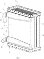
- a heat exchanger such as for example a water charge air cooler, is shown in the drawings.
- the heat exchanger comprises an inlet header plate 11 and an outlet header plate 21, both of metal material, such as for example aluminium.
- These header plates 11 and 21 are intended to be connected in a known way to an inlet header tank (not shown) and to an outlet header tank (not shown), respectively.
- Figure 2 also shows gaskets 13 and 23 for sealing connections between the header plates and the respective header tanks.
- the heat exchanger 1 further comprises a core 30 comprising a plurality of parallel flat tubes 31 extending between the header plates 11 and 21.
- the tubes 31 are of metal material, such as for example aluminium.
- Each tube 31 has opposite ends inserted into openings or slots formed in one or the other of the header plates 11, 21, respectively.
- Each tube 31 has an approximately rectangular cross-section, and comprises a pair of opposite long sidewalls and a pair of opposite short sidewalls which interconnect the long sidewalls and are shorter than the long sidewalls. In the drawings, only one of the short sidewalls is designated with a reference number, 31a.
- a first fluid particularly a gaseous fluid such as, for example, air or a gaseous mixture
- a gaseous fluid such as, for example, air or a gaseous mixture
- the heat exchanger can be connected to a fluid circuit for the first fluid (not shown), comprising for example an intake system of an internal combustion engine.
- a second fluid particularly a liquid coolant such as, for example, water or a water-based mixture, is designed to flow around the core 30 and through gaps between the tubes 31, and exchange heat with the first fluid flowing into the tubes 31.
- Finned plates 32 are arranged into the gaps between the tubes 31, as well as adjacent to tubes 31 at opposite ends of the core 30.
- the heat exchanger further comprises a jacket 40 of metal material, such as for example aluminium.
- the jacket 40 is connected to the header plates 11 and 21 in a fluid-tight manner and defines with the header plates 11 and 21 an inner volume for receiving/conveying the second fluid.
- the tubes 31 are placed within this inner volume formed by the jacket 40 and the header plates 11 and 21.
- the jacket 40 has a rectangular cross-section and comprises a pair of opposite first walls 41 and 42 and a pair of opposite second walls 43 and 44 interconnecting the first walls 41 and 42.
- the walls 41-44 are connected to each other and to the header plates 11, 21 in a conventional manner.
- the heat exchanger further comprises an inlet fluid channel 51 and an outlet fluid channel 61 for conveying the second fluid to and from the inner volume formed by the jacket 40 along with the header plates 11, 21.
- Both fluid channels 51, 61 are of metal material, such as for example aluminium.
- Each fluid channel 51, 61 is joined to a wall of the jacket 40.
- both fluid channels 51, 61 are joined to one of the first walls, 41, of the jacket 40.
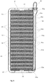
- each fluid channel 51, 61 is formed as an elongate, concave shell, whose rim 51a, 61a is joined to the wall 41 of the jacket 40 (see Figures 4 and 5 ). Therefore, the concave side of each fluid channel 51, 61 faces towards the wall 41 of the jacket 40.
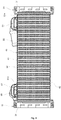
- Each fluid channel 51, 61 is in fluid communication with the inner volume of the jacket 40 through a respective opening 53, 63 formed through the wall 41 of the jacket 40.
- this wall 41 is, on an opposite side relative to the fluid channels 51 and 61, joined to the short sidewalls 31a of the tubes 31.
- all walls 41-44 of the jacket 40, particularly the first walls 41, 42, can be joined to sidewalls of the tubes 31, particularly to the short sidewalls of the tubes 31.
- Figure 2 also shows inlet and outlet fluid connectors, 55 and 65, which are fixed to the inlet fluid channel 51 and the outlet fluid channel 61, respectively, to connect the heat exchanger to a fluid circuit for the second fluid (not shown), such as for example a liquid coolant circuit.
- a fluid circuit for the second fluid such as for example a liquid coolant circuit.
- the tubes 31, header plates 11 and 21, and jacket 40 are joined to each other, fluid channels 51 and 61 are joined to the jacket 40, and connectors 55 and 65 are joined to the fluid channels 51 and 61 in a conventional manner, particularly by brazing.
- the first wall 41 of the jacket 40 through which the openings 53 and 63 are formed comprises, at each opening 53, 63, a plurality of tube covering extensions 41a, 41b, extending between opposite edges of the opening 53, 63. Therefore, at each opening 53, 63 the tube covering extensions 41a, 41b define a plurality of slots 53a, 63a alternating with the tube covering extensions 41a, 41b.
- Each tube covering extension 41a, 41b is joined to a respective sidewall 31a of a respective tube 31.
- each tube 31 is covered by the wall 41 of the jacket over its entire length comprised between the header plates 11, 21, including its portions at the openings 53 and 63 where the tube 31 is covered by the respective tube covering extensions 41a, 41b of the jacket 40.
- each tube covering extension 41a, 41b is brazed to the sidewall 31a of the respective tube 31 along with the whole jacket 40.
- each slot 53a, 63a is overlapping with a respective gap between adjacent tubes 31, or between a tube 31 and a second wall 43, 44 of the jacket 40, in order to allow fluid communication between the inner volume of the jacket 40 and the fluid channels 51, 61.
- the tube covering extensions 41a, 41b are formed in one piece with the wall 41 of the jacket 40. They can be obtained, for example, through a punching process applied to a metal sheet from which the wall 41 of the jacket 40 is to be formed, and through which metal sheet portions corresponding to the slots 53a and 63a are removed.
Landscapes
- Engineering & Computer Science (AREA)
- Physics & Mathematics (AREA)
- Mechanical Engineering (AREA)
- General Engineering & Computer Science (AREA)
- Thermal Sciences (AREA)
- Geometry (AREA)
- Chemical & Material Sciences (AREA)
- Combustion & Propulsion (AREA)
- Heat-Exchange Devices With Radiators And Conduit Assemblies (AREA)
- Details Of Heat-Exchange And Heat-Transfer (AREA)
Claims (5)
- Echangeur de chaleur comprenant :une pluralité de tuyaux (31) parallèles pour transporter un premier fluide,une paire de plaques de tête (11, 21), chacune ayant une pluralité d'ouvertures dans lesquelles des extrémités respectives des tuyaux sont insérées de façon étanche au fluide,une chemise (40) reliée aux plaques de tête (11, 21) de façon étanche au fluide et définissant avec les plaques de tête (11, 21) un volume intérieur pour recevoir un deuxième fluide, les tuyaux (31) étant placés à l'intérieur dudit volume, etun canal pour fluide (51, 61) attaché à une paroi (41) de la chemise (40), le canal pour fluide (51, 61) étant en liaison fluidique avec le volume intérieur par une ouverture (53, 63) formée à travers la paroi (41), la paroi (41) étant attachée, sur un côté opposé par rapport au canal pour fluide (51, 61), à des parois latérales (31a) des tuyaux (31),caractérisé en ce que la paroi (41) de la chemise (40) comprend une pluralité d'extensions de couverture de tuyau (41a, 41b) s'étendant entre des bords opposés de l'ouverture (53, 63) et définissant une pluralité de fentes (53a, 63a) en alternance avec les extensions de couverture de tuyau (41a, 41b), chaque extension de couverture de tuyau (41a, 41b) étant reliée à une paroi latérale (31a) respective d'un tuyau (31) respectif.
- Echangeur de chaleur selon la revendication 1, caractérisé en ce qu'une pluralité d'espaces sont définis en alternance avec les tuyaux (31), et chaque fente (53a, 63a) se chevauchant avec un espace respectif pour permettre une liaison fluidique entre le volume intérieur de la chemise (40) et le canal pour fluide (51, 61).
- Echangeur de chaleur selon la revendication 1 ou 2, caractérisé en ce que la paroi (41) de la chemise (40) et les extensions de couverture de tuyau (41a, 41b) sont soudées sur les parois latérales (31a) des tuyaux (31).
- Echangeur de chaleur selon l'une des revendications 1 à 3, caractérisé en ce que le canal pour fluide (51, 61) est soudé sur la paroi latérale (41) de la chemise (40).
- Echangeur de chaleur selon l'une des revendications précédentes, caractérisé en ce que les tuyaux (31) sont configurés pour transporter un fluide gazeux et en ce que la chemise (40) est configurée pour recevoir un réfrigérant liquide.
Priority Applications (4)
| Application Number | Priority Date | Filing Date | Title |
|---|---|---|---|
| EP18398005.1A EP3567331B1 (fr) | 2018-05-09 | 2018-05-09 | Échangeur de chaleur |
| JP2019080860A JP7411337B2 (ja) | 2018-05-09 | 2019-04-22 | 熱交換器 |
| US16/390,146 US10989487B2 (en) | 2018-05-09 | 2019-04-22 | Heat exchanger |
| CN201910378835.3A CN110470156A (zh) | 2018-05-09 | 2019-05-08 | 热交换器 |
Applications Claiming Priority (1)
| Application Number | Priority Date | Filing Date | Title |
|---|---|---|---|
| EP18398005.1A EP3567331B1 (fr) | 2018-05-09 | 2018-05-09 | Échangeur de chaleur |
Publications (2)
| Publication Number | Publication Date |
|---|---|
| EP3567331A1 EP3567331A1 (fr) | 2019-11-13 |
| EP3567331B1 true EP3567331B1 (fr) | 2021-12-29 |
Family
ID=62222570
Family Applications (1)
| Application Number | Title | Priority Date | Filing Date |
|---|---|---|---|
| EP18398005.1A Active EP3567331B1 (fr) | 2018-05-09 | 2018-05-09 | Échangeur de chaleur |
Country Status (4)
| Country | Link |
|---|---|
| US (1) | US10989487B2 (fr) |
| EP (1) | EP3567331B1 (fr) |
| JP (1) | JP7411337B2 (fr) |
| CN (1) | CN110470156A (fr) |
Families Citing this family (4)
| Publication number | Priority date | Publication date | Assignee | Title |
|---|---|---|---|---|
| FR3107344B1 (fr) * | 2019-12-13 | 2022-09-02 | Valeo Systemes Thermiques | Echangeur de chaleur avec collecteur rapporté. |
| GB2593929B (en) * | 2020-04-09 | 2024-04-03 | Denso Marston Ltd | Heat exchanger |
| FR3127562B1 (fr) * | 2021-09-24 | 2024-01-19 | Sogefi Air & Cooling | Dispositif de distribution de liquide caloporteur |
| FR3136277B1 (fr) * | 2022-06-01 | 2024-04-26 | Valeo Systemes Thermiques | Boîtier d’échangeur de chaleur à faisceau d’échange. |
Family Cites Families (6)
| Publication number | Priority date | Publication date | Assignee | Title |
|---|---|---|---|---|
| JP2002080203A (ja) | 2000-07-07 | 2002-03-19 | Nippon Soken Inc | 改質器 |
| JP5128908B2 (ja) | 2007-11-05 | 2013-01-23 | 東京ラヂエーター製造株式会社 | Egrクーラ |
| JP5988296B2 (ja) * | 2011-08-10 | 2016-09-07 | 臼井国際産業株式会社 | 多管式熱交換器 |
| US20150068715A1 (en) * | 2013-09-10 | 2015-03-12 | Ford Global Technologies, Llc | Heat exchanger |
| DE102014213718A1 (de) * | 2014-07-15 | 2016-01-21 | Mahle International Gmbh | Wärmeübertrager |
| EP3404247B1 (fr) * | 2016-01-12 | 2020-09-09 | T.RAD Co., Ltd. | Échangeur de chaleur de gaz d'échappement comprenant des tubes plats empilés |
-
2018
- 2018-05-09 EP EP18398005.1A patent/EP3567331B1/fr active Active
-
2019
- 2019-04-22 JP JP2019080860A patent/JP7411337B2/ja active Active
- 2019-04-22 US US16/390,146 patent/US10989487B2/en active Active
- 2019-05-08 CN CN201910378835.3A patent/CN110470156A/zh active Pending
Also Published As
| Publication number | Publication date |
|---|---|
| JP7411337B2 (ja) | 2024-01-11 |
| CN110470156A (zh) | 2019-11-19 |
| EP3567331A1 (fr) | 2019-11-13 |
| US10989487B2 (en) | 2021-04-27 |
| US20190346218A1 (en) | 2019-11-14 |
| JP2019207097A (ja) | 2019-12-05 |
Similar Documents
| Publication | Publication Date | Title |
|---|---|---|
| US10989487B2 (en) | Heat exchanger | |
| US6250380B1 (en) | Heat exchanger, especially for gases and fluids | |
| US6920918B2 (en) | Heat exchanger | |
| US9377252B2 (en) | Heat exchanger and casing for the heat exchanger | |
| US7303002B2 (en) | Fin structure, heat-transfer tube having the fin structure housed therein, and heat exchanger having the heat-transfer tube assembled therein | |
| GB2299397A (en) | Plate heat exchanger | |
| US7774937B2 (en) | Heat exchanger with divided coolant chamber | |
| EP3561426B1 (fr) | Dispositif d'échange de chaleur | |
| US20130087317A1 (en) | Internal heat exchanger with external manifolds | |
| US7073571B2 (en) | Integrated condenser oil cooler with a receiver/dryer | |
| EP3872435B1 (fr) | Échangeur de chaleur | |
| EP0628779A2 (fr) | Echangeur de chaleur | |
| EP2265882B1 (fr) | Plaque collectrice et échangeur de chaleur la comprenant | |
| EP3808954B1 (fr) | Échangeur de chaleur | |
| EP3722724B1 (fr) | Joint etanche pour echangeur de chaleur et echangeur de chaleur comprenant un tel joint. | |
| CN216205611U (zh) | 用于热交换器集管的适配器 | |
| EP3719431A2 (fr) | Refroidisseur d'air de suralimentation | |
| WO2021205169A1 (fr) | Échangeur de chaleur | |
| EP3809088B1 (fr) | Plaque d'échangeur de chaleur pour une meilleure distribution d'écoulement | |
| EP3517873B1 (fr) | Échangeur de chaleur et procédé de refroidissement d'un flux d'air chauffé | |
| EP4317889A1 (fr) | Faisceau tubulaire pour échangeur de chaleur | |
| EP3982075A1 (fr) | Échangeur de chaleur | |
| EP3809081A1 (fr) | Échangeur de chaleur | |
| CN118168358A (zh) | 换热器 | |
| CN112033186A (zh) | 集管箱、换热器及集管箱的制备方法 |
Legal Events
| Date | Code | Title | Description |
|---|---|---|---|
| PUAI | Public reference made under article 153(3) epc to a published international application that has entered the european phase |
Free format text: ORIGINAL CODE: 0009012 |
|
| STAA | Information on the status of an ep patent application or granted ep patent |
Free format text: STATUS: THE APPLICATION HAS BEEN PUBLISHED |
|
| AK | Designated contracting states |
Kind code of ref document: A1 Designated state(s): AL AT BE BG CH CY CZ DE DK EE ES FI FR GB GR HR HU IE IS IT LI LT LU LV MC MK MT NL NO PL PT RO RS SE SI SK SM TR |
|
| AX | Request for extension of the european patent |
Extension state: BA ME |
|
| STAA | Information on the status of an ep patent application or granted ep patent |
Free format text: STATUS: REQUEST FOR EXAMINATION WAS MADE |
|
| 17P | Request for examination filed |
Effective date: 20200508 |
|
| RAV | Requested validation state of the european patent: fee paid |
Extension state: MA Effective date: 20200508 |
|
| RBV | Designated contracting states (corrected) |
Designated state(s): AL AT BE BG CH CY CZ DE DK EE ES FI FR GB GR HR HU IE IS IT LI LT LU LV MC MK MT NL NO PL PT RO RS SE SI SK SM TR |
|
| REG | Reference to a national code |
Ref country code: DE Ref legal event code: R079 Ref document number: 602018028750 Country of ref document: DE Free format text: PREVIOUS MAIN CLASS: F28F0009020000 Ipc: F02B0029040000 |
|
| GRAP | Despatch of communication of intention to grant a patent |
Free format text: ORIGINAL CODE: EPIDOSNIGR1 |
|
| STAA | Information on the status of an ep patent application or granted ep patent |
Free format text: STATUS: GRANT OF PATENT IS INTENDED |
|
| RIC1 | Information provided on ipc code assigned before grant |
Ipc: F02B 29/04 20060101AFI20210616BHEP Ipc: F28F 9/02 20060101ALI20210616BHEP Ipc: F28D 21/00 20060101ALI20210616BHEP Ipc: F28D 7/16 20060101ALI20210616BHEP Ipc: F28F 9/00 20060101ALI20210616BHEP |
|
| INTG | Intention to grant announced |
Effective date: 20210715 |
|
| GRAS | Grant fee paid |
Free format text: ORIGINAL CODE: EPIDOSNIGR3 |
|
| GRAA | (expected) grant |
Free format text: ORIGINAL CODE: 0009210 |
|
| STAA | Information on the status of an ep patent application or granted ep patent |
Free format text: STATUS: THE PATENT HAS BEEN GRANTED |
|
| AK | Designated contracting states |
Kind code of ref document: B1 Designated state(s): AL AT BE BG CH CY CZ DE DK EE ES FI FR GB GR HR HU IE IS IT LI LT LU LV MC MK MT NL NO PL PT RO RS SE SI SK SM TR |
|
| REG | Reference to a national code |
Ref country code: GB Ref legal event code: FG4D |
|
| REG | Reference to a national code |
Ref country code: CH Ref legal event code: EP |
|
| REG | Reference to a national code |
Ref country code: AT Ref legal event code: REF Ref document number: 1458845 Country of ref document: AT Kind code of ref document: T Effective date: 20220115 |
|
| REG | Reference to a national code |
Ref country code: IE Ref legal event code: FG4D |
|
| REG | Reference to a national code |
Ref country code: DE Ref legal event code: R096 Ref document number: 602018028750 Country of ref document: DE |
|
| REG | Reference to a national code |
Ref country code: LT Ref legal event code: MG9D |
|
| PG25 | Lapsed in a contracting state [announced via postgrant information from national office to epo] |
Ref country code: RS Free format text: LAPSE BECAUSE OF FAILURE TO SUBMIT A TRANSLATION OF THE DESCRIPTION OR TO PAY THE FEE WITHIN THE PRESCRIBED TIME-LIMIT Effective date: 20211229 Ref country code: LT Free format text: LAPSE BECAUSE OF FAILURE TO SUBMIT A TRANSLATION OF THE DESCRIPTION OR TO PAY THE FEE WITHIN THE PRESCRIBED TIME-LIMIT Effective date: 20211229 Ref country code: FI Free format text: LAPSE BECAUSE OF FAILURE TO SUBMIT A TRANSLATION OF THE DESCRIPTION OR TO PAY THE FEE WITHIN THE PRESCRIBED TIME-LIMIT Effective date: 20211229 Ref country code: BG Free format text: LAPSE BECAUSE OF FAILURE TO SUBMIT A TRANSLATION OF THE DESCRIPTION OR TO PAY THE FEE WITHIN THE PRESCRIBED TIME-LIMIT Effective date: 20220329 |
|
| REG | Reference to a national code |
Ref country code: NL Ref legal event code: MP Effective date: 20211229 |
|
| REG | Reference to a national code |
Ref country code: AT Ref legal event code: MK05 Ref document number: 1458845 Country of ref document: AT Kind code of ref document: T Effective date: 20211229 |
|
| PG25 | Lapsed in a contracting state [announced via postgrant information from national office to epo] |
Ref country code: SE Free format text: LAPSE BECAUSE OF FAILURE TO SUBMIT A TRANSLATION OF THE DESCRIPTION OR TO PAY THE FEE WITHIN THE PRESCRIBED TIME-LIMIT Effective date: 20211229 Ref country code: NO Free format text: LAPSE BECAUSE OF FAILURE TO SUBMIT A TRANSLATION OF THE DESCRIPTION OR TO PAY THE FEE WITHIN THE PRESCRIBED TIME-LIMIT Effective date: 20220329 Ref country code: LV Free format text: LAPSE BECAUSE OF FAILURE TO SUBMIT A TRANSLATION OF THE DESCRIPTION OR TO PAY THE FEE WITHIN THE PRESCRIBED TIME-LIMIT Effective date: 20211229 Ref country code: HR Free format text: LAPSE BECAUSE OF FAILURE TO SUBMIT A TRANSLATION OF THE DESCRIPTION OR TO PAY THE FEE WITHIN THE PRESCRIBED TIME-LIMIT Effective date: 20211229 Ref country code: GR Free format text: LAPSE BECAUSE OF FAILURE TO SUBMIT A TRANSLATION OF THE DESCRIPTION OR TO PAY THE FEE WITHIN THE PRESCRIBED TIME-LIMIT Effective date: 20220330 |
|
| PG25 | Lapsed in a contracting state [announced via postgrant information from national office to epo] |
Ref country code: NL Free format text: LAPSE BECAUSE OF FAILURE TO SUBMIT A TRANSLATION OF THE DESCRIPTION OR TO PAY THE FEE WITHIN THE PRESCRIBED TIME-LIMIT Effective date: 20211229 |
|
| PG25 | Lapsed in a contracting state [announced via postgrant information from national office to epo] |
Ref country code: SM Free format text: LAPSE BECAUSE OF FAILURE TO SUBMIT A TRANSLATION OF THE DESCRIPTION OR TO PAY THE FEE WITHIN THE PRESCRIBED TIME-LIMIT Effective date: 20211229 Ref country code: SK Free format text: LAPSE BECAUSE OF FAILURE TO SUBMIT A TRANSLATION OF THE DESCRIPTION OR TO PAY THE FEE WITHIN THE PRESCRIBED TIME-LIMIT Effective date: 20211229 Ref country code: RO Free format text: LAPSE BECAUSE OF FAILURE TO SUBMIT A TRANSLATION OF THE DESCRIPTION OR TO PAY THE FEE WITHIN THE PRESCRIBED TIME-LIMIT Effective date: 20211229 Ref country code: PT Free format text: LAPSE BECAUSE OF FAILURE TO SUBMIT A TRANSLATION OF THE DESCRIPTION OR TO PAY THE FEE WITHIN THE PRESCRIBED TIME-LIMIT Effective date: 20220429 Ref country code: ES Free format text: LAPSE BECAUSE OF FAILURE TO SUBMIT A TRANSLATION OF THE DESCRIPTION OR TO PAY THE FEE WITHIN THE PRESCRIBED TIME-LIMIT Effective date: 20211229 Ref country code: EE Free format text: LAPSE BECAUSE OF FAILURE TO SUBMIT A TRANSLATION OF THE DESCRIPTION OR TO PAY THE FEE WITHIN THE PRESCRIBED TIME-LIMIT Effective date: 20211229 Ref country code: CZ Free format text: LAPSE BECAUSE OF FAILURE TO SUBMIT A TRANSLATION OF THE DESCRIPTION OR TO PAY THE FEE WITHIN THE PRESCRIBED TIME-LIMIT Effective date: 20211229 |
|
| PG25 | Lapsed in a contracting state [announced via postgrant information from national office to epo] |
Ref country code: PL Free format text: LAPSE BECAUSE OF FAILURE TO SUBMIT A TRANSLATION OF THE DESCRIPTION OR TO PAY THE FEE WITHIN THE PRESCRIBED TIME-LIMIT Effective date: 20211229 Ref country code: AT Free format text: LAPSE BECAUSE OF FAILURE TO SUBMIT A TRANSLATION OF THE DESCRIPTION OR TO PAY THE FEE WITHIN THE PRESCRIBED TIME-LIMIT Effective date: 20211229 |
|
| PG25 | Lapsed in a contracting state [announced via postgrant information from national office to epo] |
Ref country code: IS Free format text: LAPSE BECAUSE OF FAILURE TO SUBMIT A TRANSLATION OF THE DESCRIPTION OR TO PAY THE FEE WITHIN THE PRESCRIBED TIME-LIMIT Effective date: 20220429 |
|
| REG | Reference to a national code |
Ref country code: DE Ref legal event code: R097 Ref document number: 602018028750 Country of ref document: DE |
|
| PG25 | Lapsed in a contracting state [announced via postgrant information from national office to epo] |
Ref country code: DK Free format text: LAPSE BECAUSE OF FAILURE TO SUBMIT A TRANSLATION OF THE DESCRIPTION OR TO PAY THE FEE WITHIN THE PRESCRIBED TIME-LIMIT Effective date: 20211229 Ref country code: AL Free format text: LAPSE BECAUSE OF FAILURE TO SUBMIT A TRANSLATION OF THE DESCRIPTION OR TO PAY THE FEE WITHIN THE PRESCRIBED TIME-LIMIT Effective date: 20211229 |
|
| PLBE | No opposition filed within time limit |
Free format text: ORIGINAL CODE: 0009261 |
|
| STAA | Information on the status of an ep patent application or granted ep patent |
Free format text: STATUS: NO OPPOSITION FILED WITHIN TIME LIMIT |
|
| 26N | No opposition filed |
Effective date: 20220930 |
|
| REG | Reference to a national code |
Ref country code: CH Ref legal event code: PL |
|
| REG | Reference to a national code |
Ref country code: BE Ref legal event code: MM Effective date: 20220531 |
|
| GBPC | Gb: european patent ceased through non-payment of renewal fee |
Effective date: 20220509 |
|
| PG25 | Lapsed in a contracting state [announced via postgrant information from national office to epo] |
Ref country code: MC Free format text: LAPSE BECAUSE OF FAILURE TO SUBMIT A TRANSLATION OF THE DESCRIPTION OR TO PAY THE FEE WITHIN THE PRESCRIBED TIME-LIMIT Effective date: 20211229 Ref country code: LU Free format text: LAPSE BECAUSE OF NON-PAYMENT OF DUE FEES Effective date: 20220509 Ref country code: LI Free format text: LAPSE BECAUSE OF NON-PAYMENT OF DUE FEES Effective date: 20220531 Ref country code: CH Free format text: LAPSE BECAUSE OF NON-PAYMENT OF DUE FEES Effective date: 20220531 |
|
| PG25 | Lapsed in a contracting state [announced via postgrant information from national office to epo] |
Ref country code: SI Free format text: LAPSE BECAUSE OF FAILURE TO SUBMIT A TRANSLATION OF THE DESCRIPTION OR TO PAY THE FEE WITHIN THE PRESCRIBED TIME-LIMIT Effective date: 20211229 |
|
| PG25 | Lapsed in a contracting state [announced via postgrant information from national office to epo] |
Ref country code: IE Free format text: LAPSE BECAUSE OF NON-PAYMENT OF DUE FEES Effective date: 20220509 Ref country code: FR Free format text: LAPSE BECAUSE OF NON-PAYMENT OF DUE FEES Effective date: 20220531 |
|
| PG25 | Lapsed in a contracting state [announced via postgrant information from national office to epo] |
Ref country code: IT Free format text: LAPSE BECAUSE OF FAILURE TO SUBMIT A TRANSLATION OF THE DESCRIPTION OR TO PAY THE FEE WITHIN THE PRESCRIBED TIME-LIMIT Effective date: 20211229 Ref country code: GB Free format text: LAPSE BECAUSE OF NON-PAYMENT OF DUE FEES Effective date: 20220509 Ref country code: BE Free format text: LAPSE BECAUSE OF NON-PAYMENT OF DUE FEES Effective date: 20220531 |
|
| PG25 | Lapsed in a contracting state [announced via postgrant information from national office to epo] |
Ref country code: HU Free format text: LAPSE BECAUSE OF FAILURE TO SUBMIT A TRANSLATION OF THE DESCRIPTION OR TO PAY THE FEE WITHIN THE PRESCRIBED TIME-LIMIT; INVALID AB INITIO Effective date: 20180509 |
|
| PG25 | Lapsed in a contracting state [announced via postgrant information from national office to epo] |
Ref country code: MK Free format text: LAPSE BECAUSE OF FAILURE TO SUBMIT A TRANSLATION OF THE DESCRIPTION OR TO PAY THE FEE WITHIN THE PRESCRIBED TIME-LIMIT Effective date: 20211229 Ref country code: CY Free format text: LAPSE BECAUSE OF FAILURE TO SUBMIT A TRANSLATION OF THE DESCRIPTION OR TO PAY THE FEE WITHIN THE PRESCRIBED TIME-LIMIT Effective date: 20211229 |
|
| VS25 | Lapsed in a validation state [announced via postgrant information from nat. office to epo] |
Ref country code: MA Free format text: LAPSE BECAUSE OF FAILURE TO SUBMIT A TRANSLATION OF THE DESCRIPTION OR TO PAY THE FEE WITHIN THE PRESCRIBED TIME-LIMIT Effective date: 20211229 |
|
| PG25 | Lapsed in a contracting state [announced via postgrant information from national office to epo] |
Ref country code: TR Free format text: LAPSE BECAUSE OF FAILURE TO SUBMIT A TRANSLATION OF THE DESCRIPTION OR TO PAY THE FEE WITHIN THE PRESCRIBED TIME-LIMIT Effective date: 20211229 |
|
| PGFP | Annual fee paid to national office [announced via postgrant information from national office to epo] |
Ref country code: DE Payment date: 20240521 Year of fee payment: 7 |