EP3567173B1 - Alarm management module for a wastewater pumping station - Google Patents
Alarm management module for a wastewater pumping station Download PDFInfo
- Publication number
- EP3567173B1 EP3567173B1 EP18171930.3A EP18171930A EP3567173B1 EP 3567173 B1 EP3567173 B1 EP 3567173B1 EP 18171930 A EP18171930 A EP 18171930A EP 3567173 B1 EP3567173 B1 EP 3567173B1
- Authority
- EP
- European Patent Office
- Prior art keywords
- capacity
- variable
- pump
- wastewater
- level
- Prior art date
- Legal status (The legal status is an assumption and is not a legal conclusion. Google has not performed a legal analysis and makes no representation as to the accuracy of the status listed.)
- Active
Links
- 239000002351 wastewater Substances 0.000 title claims description 159
- 238000005086 pumping Methods 0.000 title claims description 88
- 238000000034 method Methods 0.000 claims description 47
- 230000004807 localization Effects 0.000 claims description 26
- 238000012545 processing Methods 0.000 claims description 10
- 230000001960 triggered effect Effects 0.000 description 18
- 101150054854 POU1F1 gene Proteins 0.000 description 15
- 238000010586 diagram Methods 0.000 description 7
- 238000012423 maintenance Methods 0.000 description 6
- 238000012544 monitoring process Methods 0.000 description 6
- 238000012986 modification Methods 0.000 description 3
- 230000004048 modification Effects 0.000 description 3
- 239000010865 sewage Substances 0.000 description 3
- 238000004065 wastewater treatment Methods 0.000 description 3
- 238000004140 cleaning Methods 0.000 description 2
- 238000004891 communication Methods 0.000 description 2
- 238000001514 detection method Methods 0.000 description 2
- 238000011161 development Methods 0.000 description 2
- 230000018109 developmental process Effects 0.000 description 2
- 230000005484 gravity Effects 0.000 description 2
- 230000002706 hydrostatic effect Effects 0.000 description 2
- 230000000630 rising effect Effects 0.000 description 2
- 238000006467 substitution reaction Methods 0.000 description 2
- 230000002159 abnormal effect Effects 0.000 description 1
- 230000006978 adaptation Effects 0.000 description 1
- 230000003139 buffering effect Effects 0.000 description 1
- 230000015556 catabolic process Effects 0.000 description 1
- 239000012141 concentrate Substances 0.000 description 1
- 238000006731 degradation reaction Methods 0.000 description 1
- 238000005516 engineering process Methods 0.000 description 1
- 230000007613 environmental effect Effects 0.000 description 1
- 239000012530 fluid Substances 0.000 description 1
- 230000000007 visual effect Effects 0.000 description 1
Images


Classifications
-
- G—PHYSICS
- G08—SIGNALLING
- G08B—SIGNALLING OR CALLING SYSTEMS; ORDER TELEGRAPHS; ALARM SYSTEMS
- G08B21/00—Alarms responsive to a single specified undesired or abnormal condition and not otherwise provided for
- G08B21/18—Status alarms
- G08B21/182—Level alarms, e.g. alarms responsive to variables exceeding a threshold
-
- E—FIXED CONSTRUCTIONS
- E03—WATER SUPPLY; SEWERAGE
- E03F—SEWERS; CESSPOOLS
- E03F5/00—Sewerage structures
- E03F5/22—Adaptations of pumping plants for lifting sewage
-
- F—MECHANICAL ENGINEERING; LIGHTING; HEATING; WEAPONS; BLASTING
- F04—POSITIVE - DISPLACEMENT MACHINES FOR LIQUIDS; PUMPS FOR LIQUIDS OR ELASTIC FLUIDS
- F04D—NON-POSITIVE-DISPLACEMENT PUMPS
- F04D15/00—Control, e.g. regulation, of pumps, pumping installations or systems
- F04D15/0088—Testing machines
Definitions
- the present disclosure relates in general to an alarm management module for a wastewater pumping station and to a method for operating a wastewater pumping station.
- Sewage or wastewater collection systems for wastewater treatment plants typically comprise one or more wastewater pits, wells or sumps for temporarily collecting and buffering wastewater.
- wastewater flows into such pits passively under gravity flow and/or actively driven through a force main.
- One, two or more pumps are usually installed in or at each pit to pump wastewater out of the pit. If the inflow of wastewater is larger than the outflow for a certain period of time, the wastewater pit, well or sump will eventually overflow. Such overflows should be prevented as much as possible to avoid environmental impact. Therefore, it is known to trigger an overflow alarm when a certain filling level of the pit is reached. Operators and/or maintenance staff are requested to intervene and take action upon such an overflow alarm.
- US 8,594,851 B1 describes a wastewater treatment system and a method for reducing energy used in operation of a wastewater treatment facility.
- GB 2460301 A describes a method of monitoring one or more sumps in order to predict an overflow condition.
- US 2007/0286737 A1 describes an apparatus, system and method for more accurately monitoring and determining pump failure.
- US 2002/0005220 A1 describes a network of sewage sumps having pumps and level detection equipment permitting controlled flow of sewage to a central treatment facility.
- US 4,369,438 B describes a sump pump detection a alarm system to indicate one or more abnormal conditions at the site of the pump to enable corrective measures to be taken before damage is done.
- US 2008/0031752 A1 describes a sump pump control system for monitoring and driving AC pumps.
- US 9,709,431 B1 describes monitoring technology and sensors for a sump pump.
- embodiments of the present disclosure trigger fewer alarms in total, but wherein a higher fraction of alarms is actually useful for operators and/or maintenance staff to intervene and take action.
- an alarm management module for a wastewater pumping station with at least one pump arranged for pumping wastewater out of a wastewater pit
- the alarm management module is configured to process at least one level variable indicative of a filling level of the wastewater pit and at least one capacity variable indicative of a pumping capacity of the wastewater pumping station, and wherein the alarm management module is configured to trigger an intervention alarm only if all of the following conditions are met:
- the at least one level variable may, for instance, be a filling height h and/or a hydrostatic pressure p h being indicative of a filling level of the wastewater pit.
- the pump(s) may be fixed-speed pump(s) or speed-controlled pump(s). In case of speed-controlled pump(s), the pumps(s) should be running at maximum speed when the at least one level variable is at or above the predetermined alarm level threshold.
- P 0 is not known, it may be approximated by 0.5 ⁇ P ref when the maximum power consumption is used as the reference power consumption.
- the capacity threshold may be a pre-defined percentage, e. g. 95%, or an absolute value.
- the capacity threshold may be adjusted and set by an operator and/or maintenance staff.
- An alarm in terms of operator intervention would be moot, for instance, if the first two above-mentioned conditions a) and b) were met, i.e. the at least one level variable is at or above a predetermined alarm level threshold and the at least one level variable is increasing, but the third above-mentioned condition c) were not met, i.e.
- the at least one capacity variable is at or above the capacity threshold.
- the inflow of wastewater into the wastewater pit is higher than the wastewater pumping station is able to pump out at maximum capacity.
- An overflow is thus inevitable and there is nothing an operator can do about it. Therefore, no intervention alarm is triggered in this case.
- the operator and/or maintenance staff who often operate a multitude of wastewater pits, can thus concentrate their efforts on those pits where an intervention alarm is actually triggered indicating that the operator can improve the situation by taking action, such as switching, repairing, exchanging, cleaning a pump or a non-return valve and/or cleaning an outflow pipe.
- the alarm management module may be further configured to trigger an information warning if all of the following conditions are met:
- the operator merely receives, in such a futile situation, an information warning instead of a moot alarm when an inevitable overflow is expected to happen.
- the capacity variable is determined relative to a statistically determined reference capacity.
- the reference capacity may, for instance, be a reference outflow q ref , a reference pressure ⁇ p ref , and/or a reference power consumption P ref , which may, for instance, be determined statistically by recording the highest value or an averaged or typical value over a defined past time period of normal faultless operation.
- the alarm management module may be configured to statistically determine the reference capacity during a time period when all of the following conditions are met:
- the at least one capacity variable may be based on
- the flow variable q may be measured by a flow meter at or downstream of an outlet of the pump(s) or estimated based on a pressure or power value.
- the power variable P may be measured by a sensor and/or based on an electrical power, voltage and/or current consumed by the pump(s).
- the electrical power consumption of the pump(s) may be used the power variable P indicative of a hydraulic power provided by the pump(s) when pumping wastewater out of the wastewater pit.
- the alarm management module may further be configured to process a plurality of pump specific capacity variables each of which is indicative of a pumping capacity of one of a plurality of pumps arranged for pumping wastewater out of the wastewater pit.
- pump specific capacity variables for each of a plurality of pumps allow monitoring the capacity of each pump constantly, regularly or sporadically during "normal" operation when the at least one level variable is below the predetermined alarm level threshold, i.e. the first condition a) for an intervention alarm is not fulfilled, and/or when the at least one level variable is not increasing, i.e. the second condition b) for an intervention alarm is not fulfilled.
- An operator may then be warned if the at least one capacity variable is below a capacity threshold, i.e. the third condition c) for an intervention alarm is fulfilled.
- An operator may decide to intervene and take action for restoring the capacity of the wastewater pumping station upon such a capacity warning.
- the pumps are preferably not operating simultaneously but in turns only one at a time.
- the total of operating hours of all pumps and associated wear are preferably evenly distributed among the pumps.
- a second, third or more pumps are preferably only switched on in addition to already running pump(s) if the wastewater level in the pit exceeds an according switch level (below the alarm level threshold).
- the second, third or more pumps that are running in addition to already running pump(s) are switched off again if the wastewater level in the pit falls below the according switch level.
- the alarm management module may be further configured to trigger a capacity warning including a problem localisation information, wherein the problem localisation information is based on whether:
- the pump specific capacity variables can be compared to add a problem localisation information to a capacity warning. For instance, if only one of the pump specific capacity variables is below the capacity threshold, a problem with the associated pump is indicated. On the other hand, if only one of the pump specific capacity variables is not below the capacity threshold, a backflow through the said pump is indicated, i.e. a non-return valve at the associated pump may be leaking. This means, that the other pump(s) are pumping wastewater back into the pit through said pump, which results in a degraded pump specific capacity variable for all other pumps.
- the alarm management module may be further configured to process a plurality of pairs of a first pump specific capacity variable and a second pump specific capacity variable, each pair being indicative of a pumping capacity of one of a plurality of pumps arranged for pumping wastewater out of the wastewater pit, and wherein the alarm management module is configured to trigger a capacity warning including a problem localisation information, wherein the problem localisation information is based on whether:
- the first pump specific capacity variable may be p i % and the second pump specific capacity variable may be C i % or P i %. It is advantageous to process a plurality of pairs of the first pump specific capacity variable and the second pump specific capacity variable in order to improve the reliability and elaborateness of the problem localisation information. For instance, when both the first pump specific capacity variable and a second pump specific capacity for each pump are processed, the redundant capacity information for each pump is more reliable, because a false capacity warning is less likely, for instance, when both the first pump specific capacity variable and the second pump specific capacity variable are below the capacity threshold. However, when the first pump specific capacity variable and the second pump specific capacity variable indicate differently, one of them may be given a higher weight for indicating a problem.
- a pipe clogging downstream of all the pumps is nevertheless indicated based on p i % weighted higher than C i % or P i % in this case.
- a simultaneous pipe clogging and problem with one pump may be indicated in the problem localisation information, when the first pump specific capacity variable p i % of all of the pumps except for said one pump are above an upper capacity threshold, e.g. 105%, and the second pump specific capacity variable C i % or P i % of all of the pumps except for said one pump are not below the capacity threshold.
- a method for operating a wastewater pumping station with at least one pump arranged for pumping wastewater out of a wastewater pit comprising:
- the method may further comprise:
- the capacity variable is determined relative to a statistically determined reference capacity.
- the reference capacity is statistically determined during a time period when all of the following conditions are met:
- the at least one capacity variable may be based on
- the at least one capacity variable may be based on at least one pressure signal or flow signal provided by at least one pressure sensor or flow sensor, respectively, at or downstream of an outlet of the at least one pump.
- the at least one capacity variable may be based on an electrical variable, such as power, voltage and/or current, consumed by the at least one pump.
- the at least one capacity variable may be based on a ratio between an actual pressure at or downstream of an outlet of the at least one pump when pumping wastewater out of the wastewater pit and a reference pressure determined during a time period when all of the following conditions are met:
- the method may further comprise:
- the method may further comprise:
- the method may further comprise:
- the alarm management module described above and/or some or all of the steps of the method described above may be implemented in form of compiled or uncompiled software code that is stored on a computer readable medium with instructions for executing the method.
- some or all method steps may be executed by software in a cloud-based system, in particular the alarm management module may be partly or in full implemented on a computer and/or in a cloud-based system.
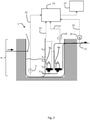
- Fig. 1 shows a wastewater pit 1 of a wastewater pumping station.
- the wastewater pit 1 has a certain height H and can be filled through an inflow port 3.
- the current level of wastewater is denoted as h and may be continuously or regularly monitored by means of a level sensor 5, e.g. a hydrostatic pressure sensor at the bottom of the wastewater pit 1 and/or an ultrasonic distance meter for determining the surface position of the wastewater in the pit 1 by detecting ultrasonic waves being reflected by the wastewater surface.
- the wastewater pit 1 may be equipped with one or more photoelectric sensors or other kind of sensors at one or more pre-defined levels for simply indicating whether the wastewater has reached the respective pre-defined level or not.
- the wastewater pumping station further comprises an outflow port 7 near the bottom of the wastewater pit 1, wherein the outflow port 7 is in fluid connection with a pump 9a for pumping wastewater out of the wastewater pit into a force main 11.
- a pump 9a for pumping wastewater out of the wastewater pit into a force main 11.
- an inlet of the pump 9a may be the outflow port 7.
- the pump 9a may be arranged, as shown in Figs. 1 and 2 , outside of the wastewater pit 1 or submerged at the bottom of the wastewater pit 1 in form of a submersible pump.
- An alarm management module 13 is signal connected with the level sensor 5 to receive a level signal indicative of a filling level of the wastewater pit 1 via wired or wireless signal connection 15.
- the alarm management module 13 is configured to process the level signal as a level variable h in order to monitor whether the level variable h is at or above a predetermined alarm level threshold h m .
- Figs. 1 and 2 show three options for a further signal connections of the alarm management module 13, any of which may be implemented alone or in combination with one or two of the other options.
- the first option is a wired or wireless signal connection 17 with a pressure sensor 19 at or downstream of the pump 9a.
- the second option is a wired or wireless signal connection 21 with power electronics of the pump 9a or a power sensor in the pump 9a.
- the third option is a wired or wireless signal connection 23 with a flow meter 25 at or downstream of the pump 9a.
- the signal connections 15, 17, 21, 23 may be separate communication channels or combined in a common communication channel or bus.
- the alarm management module 13 is configured to receive a respective pressure, power and/or flow signal via the signal connections 17, 21, 23 and to process a respective capacity variable, which is indicative of a pumping capacity of the wastewater pumping station.
- the pump(s) may be fixed-speed pump(s) or speed-controlled pump(s). In case of speed-controlled pump(s), the pumps(s) should be running at maximum speed when the at least one level variable is at or above the predetermined alarm level threshold.
- P 0 is not known, it may be approximated by 0.5 ⁇ P ref when the maximum power consumption is used as the reference power consumption.
- the flow meter 25 may be quite expensive and may require regular maintenance, it may be preferred to estimate the out-flow q.
- the flow q may be estimated by q ⁇ s ⁇ 0 ⁇ + s ⁇ 1 ⁇ ⁇ p + s ⁇ 2 ⁇ 2 P + s ⁇ 3 ⁇ , wherein s is the number of running pumps, ⁇ is the pump speed, ⁇ p is the measured pressure differential, P is the power consumption of the running pump(s), and ⁇ 0 , k 1 , ⁇ 2 and ⁇ 3 are pump parameters that may be known from the pump manufacturer or determined by calibration.
- the capacity variable may be determined relative to a predetermined or statistically determined reference capacity.
- the reference capacity may, for instance, be a reference outflow q ref , a reference pressure ⁇ p ref , and/or a reference power consumption P ref , respectively, which may, for instance, be determined statistically by recording the highest value or an averaged or typical value over a defined past time period of normal faultless operation.
- the reference outflow q ref , the reference pressure ⁇ p ref , and/or the reference power consumption P ref may be a fixed nominal value based on the layout of the wastewater pumping station and/or its pump(s).
- the alarm management module 13 is configured to trigger an intervention alarm based on both the level variable and the at least one the capacity variable for outputting the intervention alarm on an out-put device 27.
- the output device 27 may be a display and/or a loudspeaker on a mobile or stationary device for an operator to take notice of a visual and/or acoustic signal as the intervention alarm.
- An intervention alarm is only triggered by the alarm management module 13 if all of the following conditions are met:
- an intervention alarm is not triggered if only the first two conditions a) and b) are fulfilled, but not the third condition c).
- an information warning may be triggered. The operator may be informed about this situation, but not asked to intervene, because the capacity variable is high and indicates that an operator cannot significantly improve the situation by intervening anyway.
- Fig. 3 shows a chain of wastewater pumping stations being connected by respective force mains 11 through which a lower level wastewater pumping station is able to pump wastewater to the next higher level wastewater pumping station against gravity.
- the alarm management module 13 As each of the wastewater pumping stations is monitored by the alarm management module 13, it is most likely, e. g. at times of heavy rainfall, that all wastewater pumping stations would be simultaneously showing an alarm situation if the alarm management module 13 were not monitoring the at least one capacity variable p%, P% and/or C% for distinguishing between an intervention alarm and an information warning.
- the alarm management module 13 only triggers an intervention alarm for those wastewater pumping stations for which a low capacity variable p%, P% and/or C% indicates that the operator can improve the situation by intervening.
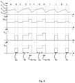
- Fig. 4 shows four diagrams of the level variable h and, according to the three options for the capacity variable, the pressure p, the power consumption P and/or the measured or estimated outflow q over time t during time periods A, B, C, D, ...,K and L of normal faultless pump cycles of the two-pump system as shown in Fig. 2 .
- Fig. 4 indicates four thresholds for the level variable h by horizontal dotted lines, i.e. a stop level threshold h 0 , a first start level threshold h 1 , a second start level threshold h 2 and an alarm level threshold h m .
- the wastewater level is increasing between the stop level threshold h 0 and the first start level threshold h 1 .
- No pump is running at this point. So, there is no outflow p and no power consumption P.
- the first one 9a of the two pumps 9a, 9b is started in the second time period B to drive an outflow q at a power consumption P generating a pressure p.
- the outflow q is higher than the inflow into the wastewater pit 1 and the level variable h drops.
- operating only one of two pumps of the wastewater pumping station means that the wastewater pumping station is running at half or less capacity.
- both pumps may be running at half speed, for instance.
- the first pump 9a stops when the level variable drops below the stop level threshold h 0 in order to prevent the pump 9a from running dry.
- the inflow is higher than during the first time period A.
- the second one 9b of the two pumps 9a, 9b is started in the fourth time period D to drive an outflow q at a power consumption P generating a pressure p.
- the pumps may be operated in alternating order to evenly distribute operating hours and corresponding wear among the pumps. This time, however, the outflow q is still lower than the inflow into the wastewater pit 1 so that the level variable h still rises during the fourth time period D.
- the first pump 9a is started in the fifth time period E in addition to the already running second pump 9b.
- the wastewater pumping station is now running at maximum capacity with all available pumps.
- the outflow close to q ref which is preferably a maximum outflow, generated together by both pumps 9a, 9b at the reference power consumption P ref , is higher than the inflow resulting in a dropping wastewater level h during the fifth time period E.
- Both pumps 9a, 9b stop when the level variable drops below the stop level threshold h 0 in order to prevent the pumps 9a, 9b from running dry.
- the time periods E and H, when the wastewater pumping station is running faultlessly at maximum capacity may be used to determine statistically the reference outflow q ref , the reference pressure ⁇ p ref , and/or the reference power consumption P ref . For instance, the highest values among several faultless pump cycles at maximum capacity may be recorded as the respective reference values. The following conditions are met during the time periods E and H:
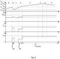
- Fig. 5 shows a situation in which the level variable h is above the alarm level threshold h m during time periods F and G. Since time period E, the level variable h is above the level threshold h 2 , so that both pumps 9a, 9b are running at maximum capacity during time periods E, F, G and H trying to reduce the wastewater level h. However, the inflow is so high that the maximum capacity of the wastewater pumping station does not suffice to prevent the level variable h from rising above the alarm level threshold h m . In time periods G and H, the inflow has reduced so that the pumps 9a, 9b can bring the wastewater level h below the alarm level threshold h m again. It is important to note that no intervention alarm is triggered by the alarm management module 13 during time periods F and G.
- the wastewater pumping station operates as pit as it gets and an operator would not be able to improve the situation by intervening.
- the problem localisation information indicates a problem with the second pump 9b. An operator is thus able to quickly intervene at the second pump 9b before or when the intervention alarm is triggered.
- Fig. 8 shows that it may be advantageous to process more than one capacity variable. This is not only because the redundancy may reduce errors, but also to gain further information about the cause of a problematic situation.
- Fig. 8 shows the three different scenarios I, II and III with a similar development of the wastewater level h over time, but different developments of the capacity variables.
- the first scenario I is caused by a clogging in one of pumps.
- the second scenario II is caused by a leakage flow back into the wastewater pit 1.
- the third scenario III is caused by a clogging of the pipe downstream of both pumps.
- the first scenario I of a problem with one of the pumps may be identified by processing a pair of capacity variables [p%, P%].
- pairs of a pump specific capacity variables [C i %, p i %], [C i %, P i %] and/or [p i %, P i %] may be processed to identify which of the pumps may be the cause of a problem.
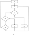
- Fig. 9 illustrates an example of method steps for the alarm handling in the wastewater pumping station.
- reference capacity values C ref , p ref and/or P ref may be determined statistically during faultless operation of the wastewater pumping station.
- the step 903 of processing the level and capacity variable may be performed before or during the step 901 of determining reference capacity values. In this case, predetermined reference capacity values may be used to start processing the capacity variables.
- step 905 If all conditions in step 905 are fulfilled, an intervention alarm is triggered in step 907. If not all conditions in step 905 are fulfilled, a further check 909 may follow, in which it is checked whether all of the following conditions are met:
- step 909 If all conditions in step 909 are fulfilled, an information warning is triggered in step 911. This means that an inevitable overflow is likely to happen and an operator's intervention would be futile. If not all conditions in step 909 are fulfilled, a further check 913 may follow, in which it is checked whether all of the following conditions are met:
- step 913 If all conditions in step 913 are fulfilled, the wastewater pumping station is properly working without any fault indication so that the first step 901 of determining reference capacity values may be performed again.
Landscapes
- Engineering & Computer Science (AREA)
- Health & Medical Sciences (AREA)
- Life Sciences & Earth Sciences (AREA)
- Hydrology & Water Resources (AREA)
- Public Health (AREA)
- Water Supply & Treatment (AREA)
- Business, Economics & Management (AREA)
- Emergency Management (AREA)
- Physics & Mathematics (AREA)
- General Physics & Mathematics (AREA)
- Mechanical Engineering (AREA)
- General Engineering & Computer Science (AREA)
- Control Of Positive-Displacement Pumps (AREA)
- Control Of Non-Positive-Displacement Pumps (AREA)
Priority Applications (7)
| Application Number | Priority Date | Filing Date | Title |
|---|---|---|---|
| EP18171930.3A EP3567173B1 (en) | 2018-05-11 | 2018-05-11 | Alarm management module for a wastewater pumping station |
| ES18171930T ES2908717T3 (es) | 2018-05-11 | 2018-05-11 | Módulo de gestión de alarmas para una estación de bombeo de aguas residuales |
| DK18171930.3T DK3567173T3 (da) | 2018-05-11 | 2018-05-11 | Alarmforvaltningsmodul for en spildevandspumpestation |
| PCT/EP2019/061211 WO2019215001A1 (en) | 2018-05-11 | 2019-05-02 | Alarm management module for a wastewater pumping station |
| US17/054,438 US11557190B2 (en) | 2018-05-11 | 2019-05-02 | Alarm management module for a wastewater pumping station |
| CN201980031809.1A CN112105788B (zh) | 2018-05-11 | 2019-05-02 | 废水泵送站的警报管理模块 |
| RU2020140632A RU2763295C1 (ru) | 2018-05-11 | 2019-05-02 | Модуль управления сигнализацией для насосной станции сточных вод |
Applications Claiming Priority (1)
| Application Number | Priority Date | Filing Date | Title |
|---|---|---|---|
| EP18171930.3A EP3567173B1 (en) | 2018-05-11 | 2018-05-11 | Alarm management module for a wastewater pumping station |
Publications (2)
| Publication Number | Publication Date |
|---|---|
| EP3567173A1 EP3567173A1 (en) | 2019-11-13 |
| EP3567173B1 true EP3567173B1 (en) | 2022-02-16 |
Family
ID=62167137
Family Applications (1)
| Application Number | Title | Priority Date | Filing Date |
|---|---|---|---|
| EP18171930.3A Active EP3567173B1 (en) | 2018-05-11 | 2018-05-11 | Alarm management module for a wastewater pumping station |
Country Status (7)
| Country | Link |
|---|---|
| US (1) | US11557190B2 (zh) |
| EP (1) | EP3567173B1 (zh) |
| CN (1) | CN112105788B (zh) |
| DK (1) | DK3567173T3 (zh) |
| ES (1) | ES2908717T3 (zh) |
| RU (1) | RU2763295C1 (zh) |
| WO (1) | WO2019215001A1 (zh) |
Families Citing this family (6)
| Publication number | Priority date | Publication date | Assignee | Title |
|---|---|---|---|---|
| US20200209112A1 (en) * | 2018-12-26 | 2020-07-02 | Intellihot, Inc. | Failure mode determination means |
| EP4001528A1 (en) | 2020-11-24 | 2022-05-25 | Xylem Europe GmbH | Method for monitoring the operation of a pump station |
| US20220268010A1 (en) * | 2021-02-23 | 2022-08-25 | Alderon Industries, Inc. | Septic system monitoring and control system |
| CN113057158B (zh) * | 2021-04-21 | 2022-07-05 | 成都大学 | 一种用于围墙底部的防刺猬挖穿结构 |
| IT202100026321A1 (it) * | 2021-10-14 | 2023-04-14 | Scova Impianti S R L | Sistema di controllo del prelievo di acqua da una riserva idrica. |
| CN117054676B (zh) * | 2023-10-13 | 2023-12-19 | 山西智合清浩环保技术服务有限公司 | 废水在线监测设备的运维智能控制系统 |
Family Cites Families (29)
| Publication number | Priority date | Publication date | Assignee | Title |
|---|---|---|---|---|
| SU413281A1 (zh) * | 1972-04-12 | 1974-01-30 | ||
| US4369438A (en) * | 1980-05-13 | 1983-01-18 | Wilhelmi Joseph R | Sump pump detection and alarm system |
| US5591010A (en) * | 1995-01-19 | 1997-01-07 | Milltronics Ltd. | Time shift control of wastewater pumping system |
| US5935449A (en) * | 1997-03-04 | 1999-08-10 | Jay R. Smith Manufacturing Co. | Automated separator of light fluids by specific gravity |
| US6378554B1 (en) * | 2000-01-14 | 2002-04-30 | Little Giant Pump Company | Controlled sewage sump network system |
| US6309539B1 (en) * | 2000-02-07 | 2001-10-30 | American Manufacturing Company, Inc. | Filtration and subsurface distribution system |
| US20020052201A1 (en) * | 2000-10-31 | 2002-05-02 | Leif Wilhelmsson | Method and system for dynamic carrier selection |
| US6578590B2 (en) * | 2001-03-21 | 2003-06-17 | Danny Leblond | Rotative cleaning and sanitizing device |
| JP4084694B2 (ja) * | 2003-04-22 | 2008-04-30 | シャープ株式会社 | 洗濯機 |
| US7221282B1 (en) * | 2004-02-24 | 2007-05-22 | Wireless Telematics Llc | Wireless wastewater system monitoring apparatus and method of use |
| US20080031752A1 (en) * | 2006-03-03 | 2008-02-07 | Littwin Kenneth M | Sump pump control system |
| US8297937B2 (en) * | 2006-06-12 | 2012-10-30 | Stak Enterprises, Inc. | Pump control apparatus, system and method |
| US7343250B1 (en) * | 2006-08-16 | 2008-03-11 | Force Flow | System and method for calculating chemical usage |
| US8594851B1 (en) | 2006-12-20 | 2013-11-26 | Data Flow Systems, Inc. | Wastewater collection flow management system and techniques |
| GB2460301A (en) * | 2008-05-30 | 2009-12-02 | Pulsar Process Measurement Ltd | Sump monitoring method and apparatus |
| US8066029B2 (en) * | 2008-06-20 | 2011-11-29 | Mcdonald William | Persuasive environmental recovery system |
| FR2936051B1 (fr) * | 2008-09-16 | 2011-08-05 | Sauermann Ind Sa | Dispositif de pilotage d'une pompe de relevage de condensats detecteur capacitif et systeme correspondants. |
| US20100122738A1 (en) * | 2008-11-17 | 2010-05-20 | David Williamson | Excess grey water disposal |
| CN202359647U (zh) * | 2011-07-28 | 2012-08-01 | 杭州聚川环保科技有限公司 | 一种用于重力流与真空结合式排水系统的污水提升器 |
| US8371821B1 (en) * | 2012-08-17 | 2013-02-12 | Nasser Fred Mehr | Green waste water pump station control system |
| US9885360B2 (en) * | 2012-10-25 | 2018-02-06 | Pentair Flow Technologies, Llc | Battery backup sump pump systems and methods |
| US9631356B2 (en) * | 2013-04-30 | 2017-04-25 | Globalfoundries Inc. | Combined sewer overflow warning and prevention system |
| US20160163175A1 (en) * | 2014-12-03 | 2016-06-09 | Bond Manufacturing Co., Inc. | Safety and fuel level communication system |
| US10602040B2 (en) * | 2015-02-27 | 2020-03-24 | I&Eye Enterprises, LLC | Wastewater monitoring system and method |
| US9709431B1 (en) * | 2015-04-14 | 2017-07-18 | Alarm.Com Incorporated | Water management sensing |
| US10967303B2 (en) * | 2018-03-08 | 2021-04-06 | Mark W. Romers | Filter backwash control system for a water or wastewater treatment system to conserve water during the filter backwash process |
| US10634133B2 (en) * | 2017-06-19 | 2020-04-28 | See Water, Inc. | Electronic systems for controlling submersible pumps |
| CN207130869U (zh) * | 2017-09-12 | 2018-03-23 | 江苏铭星供水设备有限公司 | 泵房溢水报警与保护系统 |
| US20190194928A1 (en) * | 2017-10-20 | 2019-06-27 | William Bret Boren | Distributed control system for a vacuum sewer system |
-
2018
- 2018-05-11 ES ES18171930T patent/ES2908717T3/es active Active
- 2018-05-11 EP EP18171930.3A patent/EP3567173B1/en active Active
- 2018-05-11 DK DK18171930.3T patent/DK3567173T3/da active
-
2019
- 2019-05-02 RU RU2020140632A patent/RU2763295C1/ru active
- 2019-05-02 US US17/054,438 patent/US11557190B2/en active Active
- 2019-05-02 CN CN201980031809.1A patent/CN112105788B/zh active Active
- 2019-05-02 WO PCT/EP2019/061211 patent/WO2019215001A1/en active Application Filing
Also Published As
| Publication number | Publication date |
|---|---|
| WO2019215001A1 (en) | 2019-11-14 |
| CN112105788A (zh) | 2020-12-18 |
| DK3567173T3 (da) | 2022-03-28 |
| EP3567173A1 (en) | 2019-11-13 |
| US20210233377A1 (en) | 2021-07-29 |
| US11557190B2 (en) | 2023-01-17 |
| RU2763295C1 (ru) | 2021-12-28 |
| CN112105788B (zh) | 2022-07-01 |
| ES2908717T3 (es) | 2022-05-03 |
Similar Documents
| Publication | Publication Date | Title |
|---|---|---|
| EP3567173B1 (en) | Alarm management module for a wastewater pumping station | |
| US11047392B2 (en) | System and method for determining a use condition for an appliance | |
| US12135033B2 (en) | Monitoring module and method for identifying an operating scenario in a wastewater pumping station | |
| US6721683B2 (en) | Pump motor diagnosis | |
| AU2009252910B2 (en) | Sump monitoring method and apparatus | |
| JP6234732B2 (ja) | 異常検出装置、汚水搬送ポンプ装置及び監視装置 | |
| US20130204546A1 (en) | On-line pump efficiency determining system and related method for determining pump efficiency | |
| JP2005330935A (ja) | 油圧機械、油圧機械の健康状態を監視するためのシステム及び方法 | |
| EP3259415B1 (en) | Pump station monitoring system and method | |
| US10927829B2 (en) | Pump monitoring method | |
| CN111537205A (zh) | 机械设备的诊断方法和机械设备的诊断装置 | |
| CN111247344B (zh) | 用于将泵送系统保持在运行状态的方法和装置 | |
| US20230176563A1 (en) | Method for monitoring and controlling the operation of a pump station | |
| JP6450348B2 (ja) | 真空式汚水収集装置のための中央監視装置、監視システムおよび監視方法 | |
| JP5968980B2 (ja) | 真空式汚水収集装置のための中央監視装置、監視システムおよび監視方法 | |
| US20220268010A1 (en) | Septic system monitoring and control system | |
| JP7581177B2 (ja) | 絶縁抵抗値の評価方法および電動機の診断方法 | |
| JPH07139023A (ja) | 下水道のポンプ監視システム | |
| EP4019779A1 (en) | A pump monitoring system and method for associating a current operating state of a pump system with one or more fault scenarios | |
| CN116547668A (zh) | 用于监测泵站的操作的方法 | |
| JP2019157788A (ja) | ポンプ設備及びポンプ設備の管理方法 | |
| JP2005291180A (ja) | ポンプ装置 |
Legal Events
| Date | Code | Title | Description |
|---|---|---|---|
| PUAI | Public reference made under article 153(3) epc to a published international application that has entered the european phase |
Free format text: ORIGINAL CODE: 0009012 |
|
| STAA | Information on the status of an ep patent application or granted ep patent |
Free format text: STATUS: THE APPLICATION HAS BEEN PUBLISHED |
|
| AK | Designated contracting states |
Kind code of ref document: A1 Designated state(s): AL AT BE BG CH CY CZ DE DK EE ES FI FR GB GR HR HU IE IS IT LI LT LU LV MC MK MT NL NO PL PT RO RS SE SI SK SM TR |
|
| AX | Request for extension of the european patent |
Extension state: BA ME |
|
| STAA | Information on the status of an ep patent application or granted ep patent |
Free format text: STATUS: REQUEST FOR EXAMINATION WAS MADE |
|
| 17P | Request for examination filed |
Effective date: 20200406 |
|
| RBV | Designated contracting states (corrected) |
Designated state(s): AL AT BE BG CH CY CZ DE DK EE ES FI FR GB GR HR HU IE IS IT LI LT LU LV MC MK MT NL NO PL PT RO RS SE SI SK SM TR |
|
| RIC1 | Information provided on ipc code assigned before grant |
Ipc: F04D 15/00 20060101ALI20210805BHEP Ipc: E03F 5/22 20060101AFI20210805BHEP |
|
| GRAP | Despatch of communication of intention to grant a patent |
Free format text: ORIGINAL CODE: EPIDOSNIGR1 |
|
| STAA | Information on the status of an ep patent application or granted ep patent |
Free format text: STATUS: GRANT OF PATENT IS INTENDED |
|
| INTG | Intention to grant announced |
Effective date: 20211001 |
|
| GRAS | Grant fee paid |
Free format text: ORIGINAL CODE: EPIDOSNIGR3 |
|
| GRAA | (expected) grant |
Free format text: ORIGINAL CODE: 0009210 |
|
| STAA | Information on the status of an ep patent application or granted ep patent |
Free format text: STATUS: THE PATENT HAS BEEN GRANTED |
|
| AK | Designated contracting states |
Kind code of ref document: B1 Designated state(s): AL AT BE BG CH CY CZ DE DK EE ES FI FR GB GR HR HU IE IS IT LI LT LU LV MC MK MT NL NO PL PT RO RS SE SI SK SM TR |
|
| REG | Reference to a national code |
Ref country code: GB Ref legal event code: FG4D |
|
| REG | Reference to a national code |
Ref country code: CH Ref legal event code: EP |
|
| REG | Reference to a national code |
Ref country code: DE Ref legal event code: R096 Ref document number: 602018030805 Country of ref document: DE |
|
| REG | Reference to a national code |
Ref country code: AT Ref legal event code: REF Ref document number: 1468956 Country of ref document: AT Kind code of ref document: T Effective date: 20220315 |
|
| REG | Reference to a national code |
Ref country code: IE Ref legal event code: FG4D |
|
| REG | Reference to a national code |
Ref country code: DK Ref legal event code: T3 Effective date: 20220324 |
|
| REG | Reference to a national code |
Ref country code: ES Ref legal event code: FG2A Ref document number: 2908717 Country of ref document: ES Kind code of ref document: T3 Effective date: 20220503 |
|
| REG | Reference to a national code |
Ref country code: LT Ref legal event code: MG9D |
|
| REG | Reference to a national code |
Ref country code: NL Ref legal event code: MP Effective date: 20220216 |
|
| REG | Reference to a national code |
Ref country code: AT Ref legal event code: MK05 Ref document number: 1468956 Country of ref document: AT Kind code of ref document: T Effective date: 20220216 |
|
| PG25 | Lapsed in a contracting state [announced via postgrant information from national office to epo] |
Ref country code: SE Free format text: LAPSE BECAUSE OF FAILURE TO SUBMIT A TRANSLATION OF THE DESCRIPTION OR TO PAY THE FEE WITHIN THE PRESCRIBED TIME-LIMIT Effective date: 20220216 Ref country code: RS Free format text: LAPSE BECAUSE OF FAILURE TO SUBMIT A TRANSLATION OF THE DESCRIPTION OR TO PAY THE FEE WITHIN THE PRESCRIBED TIME-LIMIT Effective date: 20220216 Ref country code: PT Free format text: LAPSE BECAUSE OF FAILURE TO SUBMIT A TRANSLATION OF THE DESCRIPTION OR TO PAY THE FEE WITHIN THE PRESCRIBED TIME-LIMIT Effective date: 20220616 Ref country code: NO Free format text: LAPSE BECAUSE OF FAILURE TO SUBMIT A TRANSLATION OF THE DESCRIPTION OR TO PAY THE FEE WITHIN THE PRESCRIBED TIME-LIMIT Effective date: 20220516 Ref country code: NL Free format text: LAPSE BECAUSE OF FAILURE TO SUBMIT A TRANSLATION OF THE DESCRIPTION OR TO PAY THE FEE WITHIN THE PRESCRIBED TIME-LIMIT Effective date: 20220216 Ref country code: LT Free format text: LAPSE BECAUSE OF FAILURE TO SUBMIT A TRANSLATION OF THE DESCRIPTION OR TO PAY THE FEE WITHIN THE PRESCRIBED TIME-LIMIT Effective date: 20220216 Ref country code: HR Free format text: LAPSE BECAUSE OF FAILURE TO SUBMIT A TRANSLATION OF THE DESCRIPTION OR TO PAY THE FEE WITHIN THE PRESCRIBED TIME-LIMIT Effective date: 20220216 Ref country code: BG Free format text: LAPSE BECAUSE OF FAILURE TO SUBMIT A TRANSLATION OF THE DESCRIPTION OR TO PAY THE FEE WITHIN THE PRESCRIBED TIME-LIMIT Effective date: 20220516 |
|
| PG25 | Lapsed in a contracting state [announced via postgrant information from national office to epo] |
Ref country code: PL Free format text: LAPSE BECAUSE OF FAILURE TO SUBMIT A TRANSLATION OF THE DESCRIPTION OR TO PAY THE FEE WITHIN THE PRESCRIBED TIME-LIMIT Effective date: 20220216 Ref country code: LV Free format text: LAPSE BECAUSE OF FAILURE TO SUBMIT A TRANSLATION OF THE DESCRIPTION OR TO PAY THE FEE WITHIN THE PRESCRIBED TIME-LIMIT Effective date: 20220216 Ref country code: GR Free format text: LAPSE BECAUSE OF FAILURE TO SUBMIT A TRANSLATION OF THE DESCRIPTION OR TO PAY THE FEE WITHIN THE PRESCRIBED TIME-LIMIT Effective date: 20220517 Ref country code: FI Free format text: LAPSE BECAUSE OF FAILURE TO SUBMIT A TRANSLATION OF THE DESCRIPTION OR TO PAY THE FEE WITHIN THE PRESCRIBED TIME-LIMIT Effective date: 20220216 Ref country code: AT Free format text: LAPSE BECAUSE OF FAILURE TO SUBMIT A TRANSLATION OF THE DESCRIPTION OR TO PAY THE FEE WITHIN THE PRESCRIBED TIME-LIMIT Effective date: 20220216 |
|
| PG25 | Lapsed in a contracting state [announced via postgrant information from national office to epo] |
Ref country code: IS Free format text: LAPSE BECAUSE OF FAILURE TO SUBMIT A TRANSLATION OF THE DESCRIPTION OR TO PAY THE FEE WITHIN THE PRESCRIBED TIME-LIMIT Effective date: 20220617 |
|
| REG | Reference to a national code |
Ref country code: DE Ref legal event code: R082 Ref document number: 602018030805 Country of ref document: DE |
|
| PG25 | Lapsed in a contracting state [announced via postgrant information from national office to epo] |
Ref country code: SM Free format text: LAPSE BECAUSE OF FAILURE TO SUBMIT A TRANSLATION OF THE DESCRIPTION OR TO PAY THE FEE WITHIN THE PRESCRIBED TIME-LIMIT Effective date: 20220216 Ref country code: SK Free format text: LAPSE BECAUSE OF FAILURE TO SUBMIT A TRANSLATION OF THE DESCRIPTION OR TO PAY THE FEE WITHIN THE PRESCRIBED TIME-LIMIT Effective date: 20220216 Ref country code: RO Free format text: LAPSE BECAUSE OF FAILURE TO SUBMIT A TRANSLATION OF THE DESCRIPTION OR TO PAY THE FEE WITHIN THE PRESCRIBED TIME-LIMIT Effective date: 20220216 Ref country code: EE Free format text: LAPSE BECAUSE OF FAILURE TO SUBMIT A TRANSLATION OF THE DESCRIPTION OR TO PAY THE FEE WITHIN THE PRESCRIBED TIME-LIMIT Effective date: 20220216 Ref country code: CZ Free format text: LAPSE BECAUSE OF FAILURE TO SUBMIT A TRANSLATION OF THE DESCRIPTION OR TO PAY THE FEE WITHIN THE PRESCRIBED TIME-LIMIT Effective date: 20220216 |
|
| REG | Reference to a national code |
Ref country code: DE Ref legal event code: R097 Ref document number: 602018030805 Country of ref document: DE |
|
| PG25 | Lapsed in a contracting state [announced via postgrant information from national office to epo] |
Ref country code: AL Free format text: LAPSE BECAUSE OF FAILURE TO SUBMIT A TRANSLATION OF THE DESCRIPTION OR TO PAY THE FEE WITHIN THE PRESCRIBED TIME-LIMIT Effective date: 20220216 |
|
| PLBE | No opposition filed within time limit |
Free format text: ORIGINAL CODE: 0009261 |
|
| STAA | Information on the status of an ep patent application or granted ep patent |
Free format text: STATUS: NO OPPOSITION FILED WITHIN TIME LIMIT |
|
| REG | Reference to a national code |
Ref country code: CH Ref legal event code: PL |
|
| REG | Reference to a national code |
Ref country code: BE Ref legal event code: MM Effective date: 20220531 |
|
| 26N | No opposition filed |
Effective date: 20221117 |
|
| PG25 | Lapsed in a contracting state [announced via postgrant information from national office to epo] |
Ref country code: MC Free format text: LAPSE BECAUSE OF FAILURE TO SUBMIT A TRANSLATION OF THE DESCRIPTION OR TO PAY THE FEE WITHIN THE PRESCRIBED TIME-LIMIT Effective date: 20220216 Ref country code: LU Free format text: LAPSE BECAUSE OF NON-PAYMENT OF DUE FEES Effective date: 20220511 Ref country code: LI Free format text: LAPSE BECAUSE OF NON-PAYMENT OF DUE FEES Effective date: 20220531 Ref country code: CH Free format text: LAPSE BECAUSE OF NON-PAYMENT OF DUE FEES Effective date: 20220531 |
|
| PG25 | Lapsed in a contracting state [announced via postgrant information from national office to epo] |
Ref country code: SI Free format text: LAPSE BECAUSE OF FAILURE TO SUBMIT A TRANSLATION OF THE DESCRIPTION OR TO PAY THE FEE WITHIN THE PRESCRIBED TIME-LIMIT Effective date: 20220216 |
|
| PG25 | Lapsed in a contracting state [announced via postgrant information from national office to epo] |
Ref country code: IE Free format text: LAPSE BECAUSE OF NON-PAYMENT OF DUE FEES Effective date: 20220511 Ref country code: FR Free format text: LAPSE BECAUSE OF NON-PAYMENT OF DUE FEES Effective date: 20220531 |
|
| PG25 | Lapsed in a contracting state [announced via postgrant information from national office to epo] |
Ref country code: BE Free format text: LAPSE BECAUSE OF NON-PAYMENT OF DUE FEES Effective date: 20220531 |
|
| PG25 | Lapsed in a contracting state [announced via postgrant information from national office to epo] |
Ref country code: IT Free format text: LAPSE BECAUSE OF FAILURE TO SUBMIT A TRANSLATION OF THE DESCRIPTION OR TO PAY THE FEE WITHIN THE PRESCRIBED TIME-LIMIT Effective date: 20220216 |
|
| PG25 | Lapsed in a contracting state [announced via postgrant information from national office to epo] |
Ref country code: HU Free format text: LAPSE BECAUSE OF FAILURE TO SUBMIT A TRANSLATION OF THE DESCRIPTION OR TO PAY THE FEE WITHIN THE PRESCRIBED TIME-LIMIT; INVALID AB INITIO Effective date: 20180511 |
|
| PG25 | Lapsed in a contracting state [announced via postgrant information from national office to epo] |
Ref country code: MK Free format text: LAPSE BECAUSE OF FAILURE TO SUBMIT A TRANSLATION OF THE DESCRIPTION OR TO PAY THE FEE WITHIN THE PRESCRIBED TIME-LIMIT Effective date: 20220216 Ref country code: CY Free format text: LAPSE BECAUSE OF FAILURE TO SUBMIT A TRANSLATION OF THE DESCRIPTION OR TO PAY THE FEE WITHIN THE PRESCRIBED TIME-LIMIT Effective date: 20220216 |
|
| PGFP | Annual fee paid to national office [announced via postgrant information from national office to epo] |
Ref country code: GB Payment date: 20240521 Year of fee payment: 7 |
|
| PGFP | Annual fee paid to national office [announced via postgrant information from national office to epo] |
Ref country code: DE Payment date: 20240521 Year of fee payment: 7 |
|
| PGFP | Annual fee paid to national office [announced via postgrant information from national office to epo] |
Ref country code: DK Payment date: 20240527 Year of fee payment: 7 |
|
| PGFP | Annual fee paid to national office [announced via postgrant information from national office to epo] |
Ref country code: ES Payment date: 20240627 Year of fee payment: 7 |
|
| PG25 | Lapsed in a contracting state [announced via postgrant information from national office to epo] |
Ref country code: MT Free format text: LAPSE BECAUSE OF FAILURE TO SUBMIT A TRANSLATION OF THE DESCRIPTION OR TO PAY THE FEE WITHIN THE PRESCRIBED TIME-LIMIT Effective date: 20220216 |