JP2005291180A - ポンプ装置 - Google Patents
ポンプ装置 Download PDFInfo
- Publication number
- JP2005291180A JP2005291180A JP2004111354A JP2004111354A JP2005291180A JP 2005291180 A JP2005291180 A JP 2005291180A JP 2004111354 A JP2004111354 A JP 2004111354A JP 2004111354 A JP2004111354 A JP 2004111354A JP 2005291180 A JP2005291180 A JP 2005291180A
- Authority
- JP
- Japan
- Prior art keywords
- pump
- temperature
- water
- pressure
- controller
- Prior art date
- Legal status (The legal status is an assumption and is not a legal conclusion. Google has not performed a legal analysis and makes no representation as to the accuracy of the status listed.)
- Pending
Links
- XLYOFNOQVPJJNP-UHFFFAOYSA-N water Substances O XLYOFNOQVPJJNP-UHFFFAOYSA-N 0.000 claims abstract description 80
- 238000007599 discharging Methods 0.000 claims abstract 2
- 230000007423 decrease Effects 0.000 claims description 19
- 239000012530 fluid Substances 0.000 claims description 2
- 238000005086 pumping Methods 0.000 claims 1
- 238000012423 maintenance Methods 0.000 abstract description 6
- 230000003247 decreasing effect Effects 0.000 abstract description 3
- 239000007788 liquid Substances 0.000 abstract 1
- 230000005856 abnormality Effects 0.000 description 11
- 238000001514 detection method Methods 0.000 description 9
- 238000007689 inspection Methods 0.000 description 6
- 238000013021 overheating Methods 0.000 description 6
- 238000000926 separation method Methods 0.000 description 6
- 239000000306 component Substances 0.000 description 4
- 230000004224 protection Effects 0.000 description 4
- 230000002159 abnormal effect Effects 0.000 description 3
- 238000010586 diagram Methods 0.000 description 3
- 230000000694 effects Effects 0.000 description 3
- 238000013461 design Methods 0.000 description 2
- 238000007710 freezing Methods 0.000 description 2
- 239000008400 supply water Substances 0.000 description 2
- 230000001360 synchronised effect Effects 0.000 description 2
- 239000002349 well water Substances 0.000 description 2
- 235000020681 well water Nutrition 0.000 description 2
- 230000002528 anti-freeze Effects 0.000 description 1
- 239000004020 conductor Substances 0.000 description 1
- 239000008358 core component Substances 0.000 description 1
- 230000006870 function Effects 0.000 description 1
- 230000006698 induction Effects 0.000 description 1
- 230000010354 integration Effects 0.000 description 1
- WABPQHHGFIMREM-UHFFFAOYSA-N lead(0) Chemical compound [Pb] WABPQHHGFIMREM-UHFFFAOYSA-N 0.000 description 1
- 230000007257 malfunction Effects 0.000 description 1
- 238000012986 modification Methods 0.000 description 1
- 230000004048 modification Effects 0.000 description 1
- 238000012544 monitoring process Methods 0.000 description 1
- 230000000149 penetrating effect Effects 0.000 description 1
- 230000002265 prevention Effects 0.000 description 1
- 238000012545 processing Methods 0.000 description 1
- 239000011347 resin Substances 0.000 description 1
- 229920005989 resin Polymers 0.000 description 1
- 230000000717 retained effect Effects 0.000 description 1
- 229910001220 stainless steel Inorganic materials 0.000 description 1
- 239000010935 stainless steel Substances 0.000 description 1
- 238000003756 stirring Methods 0.000 description 1
- 238000012546 transfer Methods 0.000 description 1
- 238000011144 upstream manufacturing Methods 0.000 description 1
Images
Landscapes
- Control Of Positive-Displacement Pumps (AREA)
- Control Of Non-Positive-Displacement Pumps (AREA)
Abstract
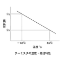
【解決手段】 流体を吐出するポンプ310と、ポンプ310中の水の温度を検出する温度検出器であって、温度上昇で抵抗値が低下し、温度低下で抵抗値が上昇する特性の温度検出器329と、温度検出器329で検出された温度が第1の所定の閾値を越えたらポンプ310の運転を停止する制御器230とを備え、制御器230は、温度検出器329で検出された温度が前記第1の所定の閾値よりも低い第2の所定の閾値を下回ったら、警報信号を出力するように構成されるポンプ装置。
【選択図】 図6
Description
また、制御器230が、温度検出器329で検出された温度が前記第2の所定の閾値を下回ったら、ポンプ310を所定の時間間隔で強制的に停止するように構成するときは、温度異常が生じたままポンプを長時間運転することがないポンプ装置を提供することが可能となる。
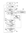
自動発停には、大きく分けて次の2種類がある:
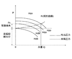
(1)流量・圧力に基づく運転・停止の切換(正常時の自動発停)
(2)異常時の保護のための停止及びリトライによる運転再開(異常時の自動発停)
(1)の場合は、DCBLコントローラ235への発停信号は運転状態のままとなっている。停止するときは、Ve=0とするだけで、発停信号は運転中の状態から変わらない。
(2)の場合は、一部の保護(例えばIPM232のエラー)では、DCBLコントローラ235への発停信号を停止状態とするとともに、Ve=0とするが、その他の保護では、Ve=0とするだけである。
異常に対するダブルチェック機能を残すために、サーミスタ329の抵抗値がΩ2を越えているか、言い換えればポンプ異常低温の現象が起こっているかを判断する(S8)。
またここでいう警報信号は、必ずしもランプ表示させたりする信号として用いるものに限らず、前記ポンプ一旦停止モードに入れるための信号として用いるものであってもよい。すなわち、ランプ表示させたりする信号とポンプ一旦停止モードに入れるための信号とを2つ出力してもよいし、一つの信号を両方の目的に用いてもよい。
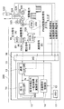
12 CPU
13 速度コントローラ部
14 圧力コントローラ部
15 推定末端圧力一定制御用演算部
16 自動発停制御部
17 メモリー
18 I/O
19 A/D
20 D/A
112 気水分離室
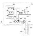
201 給水装置
210 電動機
211 電動機本体
230 インバータ装置
232 IPM素子
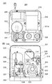
309 吸込管
310 ポンプ
311 羽根車
312 ポンプケーシング
313 ポンプケーシングカバー
321 チェッキ弁
322 圧力タンク
323 圧力センサ
324 フロースイッチ
325 吐出管
326 吸込口
327 吐出口
328 呼水栓
329 温度センサ
331 ユニットカバー
331a ユニットカバー開口(吸込側)
331b ユニットカバー開口(吐出側)
332 ユニットベース
333、334 凍結防止ヒータ
L レベル
S 地上
W 水
Well 井戸
Claims (3)
- 流体を吐出するポンプと;
前記ポンプ中の水の温度を検出する温度検出器であって、温度上昇で抵抗値が低下し、温度低下で抵抗値が上昇する特性の温度検出器と;
前記温度検出器で検出された温度が第1の所定の閾値を越えたら前記ポンプの運転を停止する制御器とを備え;
前記制御器は、前記温度検出器で検出された温度が前記第1の所定の閾値よりも低い第2の所定の閾値を下回ったら、警報信号を出力するように構成された;
ポンプ装置。 - 前記制御器は、前記温度検出器で検出された温度が前記第2の所定の閾値を下回ったら、前記ポンプを所定の時間間隔で強制的に停止するように構成された、請求項1に記載のポンプ装置。
- 前記制御器は、前記ポンプを、吐出側の圧力低下で始動するようするように構成された、請求項1又は請求項2に記載のポンプ装置。
Priority Applications (1)
| Application Number | Priority Date | Filing Date | Title |
|---|---|---|---|
| JP2004111354A JP2005291180A (ja) | 2004-04-05 | 2004-04-05 | ポンプ装置 |
Applications Claiming Priority (1)
| Application Number | Priority Date | Filing Date | Title |
|---|---|---|---|
| JP2004111354A JP2005291180A (ja) | 2004-04-05 | 2004-04-05 | ポンプ装置 |
Publications (1)
| Publication Number | Publication Date |
|---|---|
| JP2005291180A true JP2005291180A (ja) | 2005-10-20 |
Family
ID=35324378
Family Applications (1)
| Application Number | Title | Priority Date | Filing Date |
|---|---|---|---|
| JP2004111354A Pending JP2005291180A (ja) | 2004-04-05 | 2004-04-05 | ポンプ装置 |
Country Status (1)
| Country | Link |
|---|---|
| JP (1) | JP2005291180A (ja) |
Cited By (2)
| Publication number | Priority date | Publication date | Assignee | Title |
|---|---|---|---|---|
| JP2017137800A (ja) * | 2016-02-03 | 2017-08-10 | 株式会社荏原製作所 | 給水装置、および給水装置の運転方法 |
| JP2017137799A (ja) * | 2016-02-03 | 2017-08-10 | 株式会社荏原製作所 | 給水装置、および給水装置の運転方法 |
Citations (5)
| Publication number | Priority date | Publication date | Assignee | Title |
|---|---|---|---|---|
| JPS60170091U (ja) * | 1984-04-20 | 1985-11-11 | 三洋電機株式会社 | ポンプの凍結防止装置 |
| JPS6229795A (ja) * | 1985-07-31 | 1987-02-07 | Matsushita Electric Ind Co Ltd | ポンプの保護装置 |
| JPS62240487A (ja) * | 1986-04-11 | 1987-10-21 | Hitachi Ltd | 井戸ポンプ装置 |
| JPH11153098A (ja) * | 1997-09-19 | 1999-06-08 | Nikkiso Co Ltd | キャンドモータポンプ用凍結防止装置 |
| JP2001132657A (ja) * | 1999-11-04 | 2001-05-18 | Denso Corp | 密閉型電動圧縮機 |
-
2004
- 2004-04-05 JP JP2004111354A patent/JP2005291180A/ja active Pending
Patent Citations (5)
| Publication number | Priority date | Publication date | Assignee | Title |
|---|---|---|---|---|
| JPS60170091U (ja) * | 1984-04-20 | 1985-11-11 | 三洋電機株式会社 | ポンプの凍結防止装置 |
| JPS6229795A (ja) * | 1985-07-31 | 1987-02-07 | Matsushita Electric Ind Co Ltd | ポンプの保護装置 |
| JPS62240487A (ja) * | 1986-04-11 | 1987-10-21 | Hitachi Ltd | 井戸ポンプ装置 |
| JPH11153098A (ja) * | 1997-09-19 | 1999-06-08 | Nikkiso Co Ltd | キャンドモータポンプ用凍結防止装置 |
| JP2001132657A (ja) * | 1999-11-04 | 2001-05-18 | Denso Corp | 密閉型電動圧縮機 |
Cited By (2)
| Publication number | Priority date | Publication date | Assignee | Title |
|---|---|---|---|---|
| JP2017137800A (ja) * | 2016-02-03 | 2017-08-10 | 株式会社荏原製作所 | 給水装置、および給水装置の運転方法 |
| JP2017137799A (ja) * | 2016-02-03 | 2017-08-10 | 株式会社荏原製作所 | 給水装置、および給水装置の運転方法 |
Similar Documents
| Publication | Publication Date | Title |
|---|---|---|
| US6715996B2 (en) | Method for the operation of a centrifugal pump | |
| US8133034B2 (en) | Controller for a motor and a method of controlling the motor | |
| US8360736B2 (en) | Controller for a motor and a method of controlling the motor | |
| CN101203678B (zh) | 泵、操作该泵的方法与包含该泵的泵站 | |
| US20080095639A1 (en) | Controller for a motor and a method of controlling the motor | |
| US8354809B2 (en) | Controller for a motor and a method of controlling the motor | |
| CN111902634B (zh) | 泵-电机组件的故障保护 | |
| US20110002792A1 (en) | Controller for a motor and a method of controlling the motor | |
| US20080095638A1 (en) | Controller for a motor and a method of controlling the motor | |
| US20190301480A1 (en) | Pump apparatus | |
| WO2021012884A1 (zh) | 自动排空水泵的控制方法、装置相应设备及存储介质 | |
| US20230243357A1 (en) | Bilge pump systems | |
| WO2011031784A1 (en) | Fire-extinguishing system and method for operating servo motor-driven foam pump | |
| JP4812327B2 (ja) | 給水装置 | |
| JP7069559B2 (ja) | 真空ポンプのモータ異常検出装置および真空ポンプシステム | |
| JPWO2020066629A1 (ja) | 気体圧縮機 | |
| JP6316561B2 (ja) | 給液装置の運転装置、及び給液装置 | |
| JP2005291180A (ja) | ポンプ装置 | |
| JP2002257077A (ja) | 水中ポンプ | |
| JP6303043B1 (ja) | 水中ポンプ及び水中ポンプの制御方法 | |
| JP7627905B2 (ja) | 給水装置及び該給水装置の異常検出方法 | |
| JP4504705B2 (ja) | ポンプ装置 | |
| JP3979755B2 (ja) | 給水装置 | |
| JP4843385B2 (ja) | 自動給水装置のポンプ渇水保護装置 | |
| JP4589026B2 (ja) | ポンプ装置 |
Legal Events
| Date | Code | Title | Description |
|---|---|---|---|
| A621 | Written request for application examination |
Free format text: JAPANESE INTERMEDIATE CODE: A621 Effective date: 20070329 |
|
| A977 | Report on retrieval |
Free format text: JAPANESE INTERMEDIATE CODE: A971007 Effective date: 20100309 |
|
| A131 | Notification of reasons for refusal |
Free format text: JAPANESE INTERMEDIATE CODE: A131 Effective date: 20100323 |
|
| A521 | Written amendment |
Free format text: JAPANESE INTERMEDIATE CODE: A523 Effective date: 20100520 |
|
| A131 | Notification of reasons for refusal |
Free format text: JAPANESE INTERMEDIATE CODE: A131 Effective date: 20100831 |
|
| A02 | Decision of refusal |
Free format text: JAPANESE INTERMEDIATE CODE: A02 Effective date: 20110104 |