EP3566784B1 - Adjustable vibratory drive system - Google Patents
Adjustable vibratory drive system Download PDFInfo
- Publication number
- EP3566784B1 EP3566784B1 EP19171699.2A EP19171699A EP3566784B1 EP 3566784 B1 EP3566784 B1 EP 3566784B1 EP 19171699 A EP19171699 A EP 19171699A EP 3566784 B1 EP3566784 B1 EP 3566784B1
- Authority
- EP
- European Patent Office
- Prior art keywords
- drive
- drive shafts
- controller
- shafts
- angular position
- Prior art date
- Legal status (The legal status is an assumption and is not a legal conclusion. Google has not performed a legal analysis and makes no representation as to the accuracy of the status listed.)
- Active
Links
Images



Classifications
-
- B—PERFORMING OPERATIONS; TRANSPORTING
- B07—SEPARATING SOLIDS FROM SOLIDS; SORTING
- B07B—SEPARATING SOLIDS FROM SOLIDS BY SIEVING, SCREENING, SIFTING OR BY USING GAS CURRENTS; SEPARATING BY OTHER DRY METHODS APPLICABLE TO BULK MATERIAL, e.g. LOOSE ARTICLES FIT TO BE HANDLED LIKE BULK MATERIAL
- B07B1/00—Sieving, screening, sifting, or sorting solid materials using networks, gratings, grids, or the like
- B07B1/28—Moving screens not otherwise provided for, e.g. swinging, reciprocating, rocking, tilting or wobbling screens
- B07B1/284—Moving screens not otherwise provided for, e.g. swinging, reciprocating, rocking, tilting or wobbling screens with unbalanced weights
-
- B—PERFORMING OPERATIONS; TRANSPORTING
- B06—GENERATING OR TRANSMITTING MECHANICAL VIBRATIONS IN GENERAL
- B06B—METHODS OR APPARATUS FOR GENERATING OR TRANSMITTING MECHANICAL VIBRATIONS OF INFRASONIC, SONIC, OR ULTRASONIC FREQUENCY, e.g. FOR PERFORMING MECHANICAL WORK IN GENERAL
- B06B1/00—Methods or apparatus for generating mechanical vibrations of infrasonic, sonic, or ultrasonic frequency
- B06B1/10—Methods or apparatus for generating mechanical vibrations of infrasonic, sonic, or ultrasonic frequency making use of mechanical energy
- B06B1/16—Methods or apparatus for generating mechanical vibrations of infrasonic, sonic, or ultrasonic frequency making use of mechanical energy operating with systems involving rotary unbalanced masses
- B06B1/161—Adjustable systems, i.e. where amplitude or direction of frequency of vibration can be varied
- B06B1/166—Where the phase-angle of masses mounted on counter-rotating shafts can be varied, e.g. variation of the vibration phase
-
- B—PERFORMING OPERATIONS; TRANSPORTING
- B07—SEPARATING SOLIDS FROM SOLIDS; SORTING
- B07B—SEPARATING SOLIDS FROM SOLIDS BY SIEVING, SCREENING, SIFTING OR BY USING GAS CURRENTS; SEPARATING BY OTHER DRY METHODS APPLICABLE TO BULK MATERIAL, e.g. LOOSE ARTICLES FIT TO BE HANDLED LIKE BULK MATERIAL
- B07B1/00—Sieving, screening, sifting, or sorting solid materials using networks, gratings, grids, or the like
- B07B1/28—Moving screens not otherwise provided for, e.g. swinging, reciprocating, rocking, tilting or wobbling screens
- B07B1/36—Moving screens not otherwise provided for, e.g. swinging, reciprocating, rocking, tilting or wobbling screens jigging or moving to-and-fro in more than one direction
-
- B—PERFORMING OPERATIONS; TRANSPORTING
- B07—SEPARATING SOLIDS FROM SOLIDS; SORTING
- B07B—SEPARATING SOLIDS FROM SOLIDS BY SIEVING, SCREENING, SIFTING OR BY USING GAS CURRENTS; SEPARATING BY OTHER DRY METHODS APPLICABLE TO BULK MATERIAL, e.g. LOOSE ARTICLES FIT TO BE HANDLED LIKE BULK MATERIAL
- B07B1/00—Sieving, screening, sifting, or sorting solid materials using networks, gratings, grids, or the like
- B07B1/42—Drive mechanisms, regulating or controlling devices, or balancing devices, specially adapted for screens
-
- B—PERFORMING OPERATIONS; TRANSPORTING
- B65—CONVEYING; PACKING; STORING; HANDLING THIN OR FILAMENTARY MATERIAL
- B65G—TRANSPORT OR STORAGE DEVICES, e.g. CONVEYORS FOR LOADING OR TIPPING, SHOP CONVEYOR SYSTEMS OR PNEUMATIC TUBE CONVEYORS
- B65G27/00—Jigging conveyors
- B65G27/10—Applications of devices for generating or transmitting jigging movements
- B65G27/32—Applications of devices for generating or transmitting jigging movements with means for controlling direction, frequency or amplitude of vibration or shaking movement
-
- B—PERFORMING OPERATIONS; TRANSPORTING
- B07—SEPARATING SOLIDS FROM SOLIDS; SORTING
- B07B—SEPARATING SOLIDS FROM SOLIDS BY SIEVING, SCREENING, SIFTING OR BY USING GAS CURRENTS; SEPARATING BY OTHER DRY METHODS APPLICABLE TO BULK MATERIAL, e.g. LOOSE ARTICLES FIT TO BE HANDLED LIKE BULK MATERIAL
- B07B1/00—Sieving, screening, sifting, or sorting solid materials using networks, gratings, grids, or the like
- B07B1/005—Transportable screening plants
-
- B—PERFORMING OPERATIONS; TRANSPORTING
- B65—CONVEYING; PACKING; STORING; HANDLING THIN OR FILAMENTARY MATERIAL
- B65G—TRANSPORT OR STORAGE DEVICES, e.g. CONVEYORS FOR LOADING OR TIPPING, SHOP CONVEYOR SYSTEMS OR PNEUMATIC TUBE CONVEYORS
- B65G27/00—Jigging conveyors
- B65G27/10—Applications of devices for generating or transmitting jigging movements
- B65G27/16—Applications of devices for generating or transmitting jigging movements of vibrators, i.e. devices for producing movements of high frequency and small amplitude
- B65G27/18—Mechanical devices
- B65G27/20—Mechanical devices rotating unbalanced masses
-
- B—PERFORMING OPERATIONS; TRANSPORTING
- B65—CONVEYING; PACKING; STORING; HANDLING THIN OR FILAMENTARY MATERIAL
- B65G—TRANSPORT OR STORAGE DEVICES, e.g. CONVEYORS FOR LOADING OR TIPPING, SHOP CONVEYOR SYSTEMS OR PNEUMATIC TUBE CONVEYORS
- B65G2812/00—Indexing codes relating to the kind or type of conveyors
- B65G2812/03—Vibrating conveyors
Definitions
- This invention relates to vibratory drive systems.
- the invention relates particularly to vibratory drive systems for material processing apparatus.
- Vibratory drive systems may be used in many applications.
- vibratory drive systems may be used in screening apparatus and in some feeders and conveyors.
- mechanical screening which is usually just referred to as screening, involves separating particulate material, such as rocks, sand, or other aggregate material, by particle size. Screening is used in a variety of industries including mining, quarrying, mineral processing, agriculture and recycling.
- a conventional screening apparatus comprises a body that carries one or more decks of screen media.
- a vibratory drive system is provided for vibrating the body and decks.
- a known type of vibratory drive system includes multiple, eccentrically weighted, rotatable shafts, mechanically coupled together and driven by a common motor. Each shaft carries an eccentrically mounted mass, and the respective angular positions of the masses define a phase angle between shafts.
- the coupled shafts rotate in opposite directions and cause the screening apparatus to vibrate linearly or elliptically. The characteristics of the vibrations depend on the phase angle between the shafts.
- a problem with such drive systems is that the shafts are typically mechanically locked together by, for example, gears or timing belts. Adjusting the phase angle in order to adjust the vibration characteristics, requires significant down-time for the screening apparatus and any machine of which it is part, since the drive system must be stopped to allow an operator to make the necessary mechanical adjustments. Also, drive shafts that are mechanically coupled together are limited to the type of vibration that they can cause.
- GB2034437A discloses a feeder wherein each motor drives, via a belt transmission mounted in a protective casing and via flexible couplings, a shaft with out-of-balance weights pairwise rotatably journalled in the walls of the screening box.
- the present invention provides a material processing apparatus according claim 1.
- said controller is configured to adjust the rotational speed of at least one of said drive shafts to cause at least two of said drive shafts to rotate at different speeds until a desired relative angular position of the respective centres of mass is achieved, and then to cause said at least two drive shafts to rotate at the same speed.
- Said controller may be configured to adjust the rotational speed of said at least one drive shaft in response to a change in rotational speed of another of said drive shafts.
- Said controller may be configured to receive an input indicating at least one desired rotational speed for at least one of said drive shafts, and to adjust the rotational speed of said at least one drive shaft to match said at least one desired rotational speed.
- Said controller may be configured to receive an input indicating at least one desired relative angular position of at least two of said drive shafts, and is configured to adjust the rotational speed of at least one of said drive shafts to cause said at least two drive shafts to rotate at different speeds until said at least one desired relative angular position is achieved.
- At least one of, preferably all of, said drive mechanisms is operable to rotate the respective drive shaft in either one of two rotational directions, said controller being configured to cause said respective drive shaft to rotate in a desired rotational direction.
- Said controller may be configured to receive an input indicating at least one desired rotational direction for at least one of, and preferably all of, said drive shafts.
- said plurality of drive shafts comprise first and second drive shafts, said controller being configured to adjust the rotational speed of either one or both of said first and second drive shafts to adjust the relative angular position of the respective centre of mass of said first and second drive shafts.
- Said controller may be configured to determine an actual relative angular position between first and second of said drive shafts, and to adjust the rotational speed of either one or both of said first and second drive shafts to achieve a desired relative angular position between said first and second drive shafts.
- Said controller may be configured to determine an actual relative angular position between said at least two of said drive shafts, and to adjust the rotational speed of at least one of said drive shafts to adjust the relative angular position of the respective centre of mass of at least two of said drive shafts to achieve a desired relative angular position between said at least two drive shafts
- a respective angular position sensor is coupled to each of said drive shafts for detecting an angular position of the respective drive shaft, and communicating corresponding angular position information to the controller.
- Said controller is conveniently configured to determine said relative angular position from said angular position information for the respective drive shafts.
- said angular position sensor provides information indicative of the rotational speed of the respective drive shaft.
- a rotational speed sensor is coupled to each of said drive shafts for detecting the rotational speed the respective drive shaft, and communicating corresponding speed information to the controller.
- said at least one vibrating component comprises at least one screen.
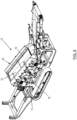
- a vibratory drive system of an embodiment of the invention is part of a material screening apparatus 10.
- the screening apparatus 10 is of a type suitable for use in separating particulate material, e.g. sand, stones, rocks or other aggregate material or recyclable material, according to size. It will be understood that drive systems embodying the invention are not limited to use with screening apparatus, and may alternatively be used in other applications, including with other material processing apparatus such as vibrating conveyors and vibrating feeders.
- the screening apparatus 10 comprises a body 14 for carrying one or more material screens.
- the screens are typically provided in one or more screening decks 12 between opposing side walls 16, 18 of the body 14.
- the body 14 is box-like in form, although it may comprise any supporting structure that is shaped and dimensioned to carry one or more screening decks 12.
- at least one end 20 of the body 14 is open to allow screened material to be removed from the screening apparatus 10, for example by a conveyor (not shown).
- the screens may take any conventional form, for example comprising bars, a mesh, a cloth or a grid.
- the screening apparatus 10 is mounted on a base 11, which may for example be part, e.g. the chassis, of a material processing system 13 of which the apparatus 10 is part.
- the screening apparatus 10 is mounted on the base 11 by a suspension system which, in the illustrated embodiment, comprises springs 22, to allow relative movement between the screening apparatus 10 and the base 11.
- the material processing system 13 may take various forms, for example including any one or more of: one or more conveyors for conveying material to or from the apparatus 10, a feeder, and/or other material processing apparatus. It will be understood that, in embodiments where the drive system 15 is incorporated into another type of material processing apparatus other than a screening apparatus, the material process apparatus may be similarly mounted on the base 11 by a suspension system.
- the vibratory drive system 15 for causes the screening apparatus 10 to vibrate.
- the drive system 15 is coupled to the body 14 in order to vibrate the body 14.
- the vibration causes the screen(s) (and/or other vibrating component(s) depending on the embodiment) carried by the body 14 to vibrate.
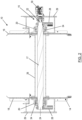
- the drive system 15 comprises at least two drive shafts 17, which are preferably but not necessarily parallel with each other.
- the screening apparatus 10 has two drive shafts 17A, 17B. In alternative embodiments (not illustrated) there may be three or more drive shafts.
- Each shaft 17 extends across the body 14, between the side walls 16, 18.
- the shafts 17 may be perpendicular with the walls 16, 18 but may alternatively be oblique with respect to the walls 16, 18.
- the shafts 17 may extend longitudinally of the body 14 (parallel or non-parallel with the walls 16, 18) for example being mounted between the ends of the body 14, or mounted on one or each side 16, 18 of the body 14.
- the shafts 17 are rotatable about their longitudinal axis, which typically is disposed transversely of the body 14.
- the shafts 17 are spaced apart in the longitudinal or transverse direction of the body 14 as applicable.
- the shafts 17 may be at the same horizontal level or at different horizontal levels.
- each shaft 17 is mounted on the body 14 by a respective bearing 20 at each end 22, 24 of the shaft 17.
- the ends 22, 24 of each shaft 17 pass through a respective aperture provided in the respective side wall 16, 18.
- the respective bearing 20 is conveniently mounted in the respective side wall 16, 18 and fits around the respective end 22, 24 of the shaft 17 to allow the shaft 17 to rotate axially.
- the portion of each shaft 17 that is located between the walls 16, 18 is located within an enclosure 26, which in the illustrated example comprises a tube.
- the enclosure 26 may be supported by the same structures that provide or include the bearing 20.
- each shaft 17 is eccentrically weighted, i.e. the mass of the shaft 17 (including any object carried by the shaft) is not evenly distributed around the shaft's rotational axis.
- each shaft 17 may be described as an "out-of-balance" rotatable shaft, in that its centre of mass (or inertia axis) is out of alignment with its centre of rotation (or geometric axis).
- each shaft 17 carries one or more mass 28 (or weight).
- the or each mass 28 is eccentrically located with respect to the rotational axis of the shaft 17 in order to unbalance the rotation of the shaft 17.
- each shaft 17 carries a respective mass 28 at each end 22, 24.
- the masses 28 are preferably angularly aligned with each other about the rotation axis of the shaft 17.
- one or more mass may be provided at one end of the shaft only.
- Simultaneous rotation of the eccentrically weighted shafts 17 causes the screening apparatus 10 to move (vibrate) with respect to the base 11.
- the respective rotational phase and rotational direction of the shafts 17 determine the type of vibratory movement that is caused (e.g. linear vibrations or orbital (e.g. circular or elliptical) vibrations).
- counter rotating shafts cause linear or elliptical vibration
- co-rotating shafts cause circular vibration.
- the relative rotating out of balance in a given rotational direction also influences vibratory movement. For example in a two shaft equal speed counter-rotating system, equal out of balance shafts results in a linear stroke, while dissimilar out of balance shafts results in an elliptical motion.
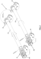
- first and second drive shafts 17A, 17B are shown schematically in end view with respective masses 28.
- the centre of mass (COM) of each shaft 17A, 17B is offset (linearly) from the respective rotational axis of the respective shaft 17A, 17B, causing each shaft to be rotationally out-of-balance.
- the angular position of the respective COM of each shaft 17A, 17B with respect to a reference angle may be referred to as the phase of the shaft 17A, 17B.
- shaft 17A is displaced by x° from the reference angle
- shaft 17B is displaced by y ° from the reference angle.
- the angle of displacement from the reference angle may be referred to as the phase angle.
- the difference between the respective phase angles of any two shafts may be referred to as the phase difference, or phase difference angle, between the shafts.
- the phase difference angle (which may also be referred to as the relative phase angle) between shafts 17A and 17B is y °- x°.
- the phase difference angle between any two or more shafts is maintained as long as the respective shafts 17 rotate at the same speed.
- the phase difference angle changes when the relative rotational speed of the respective shafts 17 changes.
- the phase difference between the shafts 17A, 17B affects the characteristics of the vibration caused by the drive system 15.
- the phase difference angle between the shafts 17A, 17B determines the size (amplitude) of the circular vibration.
- the phase difference angle determines the angle of the linear or elliptical vibration.
- the angle of linear/elliptical vibration is the angle of the major axis of the resulting screen motion relative to the screen coordinate system.
- the drive system 15 includes a respective drive mechanism for each drive shaft 17, each drive mechanism being configured to rotate a respective one of the drive shafts 17.
- each drive mechanism comprises a respective motor 30A, 30B coupled to the respective drive shaft 17A, 17B.
- the motors 30A, 30B are conveniently reversible hydraulic motors.
- Each motor 30A, 30B is mounted on the end 22 of the respective drive shaft 17A, 17B. As such, the motor 30A, 30B may be coupled to the respective shaft 17A, 17B to provide direct drive to the shaft, i.e. without any reductions as would be caused by a gear system.
- each drive mechanism comprises a reversible, variable speed motor.
- At least one but not necessarily all of the drive mechanisms are capable of rotating the respective drive shaft in both rotational directions, and are capable of rotating the respective drive shaft at variable speed. In some embodiments, all of the drive mechanism may be capable of rotating the respective drive shaft in one direction only.
- a respective housing 29 is provided for covering each end 22, 24 of each shaft 17A, 17B.
- the housings 29 cover the respective masses 28.
- each motor 30A, 30B is mounted on the outside of the respective housing 29 and is coupled to the respective shaft 17A, 17B through the housing 29.
- the drive system 15 further includes a controller 32 ( Figure 5 ) for controlling the operation of the motors 30A, 30B, or other drive mechanisms as applicable.
- the controller 32 may take any conventional form, for example comprising a suitably programmed microprocessor, microcontroller or other processor, and/or suitably configured electrical and/or electronic circuitry.
- the controller 32 is implemented as a programmable logic controller (PLC).
- PLC programmable logic controller
- the controller 32 is a proportional integral derivative (PID) controller.
- PLC programmable logic controller
- PID proportional integral derivative
- the controller 32 is programmed or otherwise configured to perform the functionality described herein.
- the preferred drive system 15 also includes an angular position sensor 34 (which may also be referred to as a shaft angle transducer) for each drive shaft 17.
- the angular positions sensors 34 may be of any conventional type, for example the potentiometer type, the encoder type (including magnetic or optical, absolute or incremental), or the resolver type.
- the respective angular position sensor 34 is coupled to, or otherwise co-operable with, the respective shaft 17 in any conventional manner.
- the coupling between the sensor 34 and the shaft 17 may involve mechanical contact with the shaft or may be contactless, and may be direct or indirect as is convenient.
- the sensors 34 may be physically connected to the shaft, or may be contactless, and may be provided as a separate component or incorporated into the motor as is convenient.
- the respective angular position sensor 34 detects the angular position of the respective shaft 17 and communicates angular position information to the controller 32.
- the angular position sensor 34 is able to, or its output may be used to, determine the rotational speed of the respective shaft 17.
- a separate respective rotational speed sensor may be provided for measuring the rotational speed of each shaft 17.
- the controller 32 receives, in use, information indicating the rotational speed of the respective shaft 17, or information from which it can determine the rotation speed of the respective shaft 17.
- the controller 32 may be located at any convenient location on the screening apparatus 10, or the material processing apparatus 13 of which the screening apparatus 10 is part, or may be located elsewhere, e.g. at a separate control station or mobile unit.
- the controller 32 may be connected to, or connectable to, the drive mechanisms and sensors by any convenient wired or wireless link for sending control signals and receiving output signals as applicable.
- the controller 32 is capable of controlling the respective drive mechanism to control rotation of each drive shaft 17 independently of the other drive shaft(s) 17.
- the controller 32 is capable of controlling the speed, and preferably also the direction, of the rotation of each drive shaft 17 by controlling the respective drive mechanism.
- at least one of, and optionally each of, the respective motors 30A, 30B is a bi-directional motor.
- each motor 30A, 30B is a variable speed motor.
- the motors 30A, 30B may be controlled by the controller 32 using any suitable control signal(s).
- the controller 32 is capable of controlling, via the respective drive mechanism, the rotation (speed and/or rotational direction) of at least one but not necessarily all of, the drive shafts 17. In any event, the controller advantageously adjusts the relative rotational speed of the drive shafts to adjust the relative angular position of their respective centre of mass.
- the controller 32 is configured to adjust the phase difference angle between shafts 17A, 17B (or any two or more shafts where there are more than two shafts) by causing the respective shafts 17A, 17B to be rotated at different speeds until a desired phase angle difference is achieved. This may be achieved by adjusting the speed of one or more of the respective shafts 17, as is convenient. Determining that the desired phase angle difference has been achieved may be performed by comparing the respective phase angle of the respective shafts 17 using the respective angular position information provided by the respective angular position sensors 34. After the desired phase angle difference is achieved, the controller 32 may cause the shafts 17A, 17B to be rotated at the same speed to maintain the desired phase angle difference.
- the input settings for rotation speed, rotation direction and/or phase difference angle may be provided as part of the programming of the controller 32 and/or may be provided by a user using any convenient user interface.
- the controller 32 receives input settings indicating any one or more of rotation direction, rotation speed, desired phase difference angle between any two or more shafts, and/or desired phase angle of any two or more shafts, and may set and/or adjust the rotation of one or more of the respective shafts 17 accordingly.
- the controller 32 may respond in real time to the input settings to set and/or adjust one or more rotation characteristic of the shaft(s) 17 accordingly.
- the controller 32 may set and/or adjust one or more rotation characteristics of the shaft(s) 17 in accordance with a pre-determined program.
- the rotation characteristics of the shaft(s) 17, including rotation speed, phase difference angle and/or rotation direction can be set and adjusted as desired without having to halt the screening process being performed by the screening apparatus 10. Accordingly the vibration characteristics of the screening apparatus 10 can be set and adjusted without having to halt the screening process.
- the controller 32 obtains desired input settings for the drive shafts 15 from a user interface or program represented in Figure 5 as 36.
- the settings may indicate any one or more of rotational speed for any one or more of the shafts 17, rotational direction for any one or more of the shafts 17 and/or phase difference angle for any two or more of the shafts 17, as applicable.
- the relevant parameter values may be provided directly as the input settings or indirectly in which case the settings may specify one or more desired vibration characteristics from which the relevant parameter values can be determined.
- the first drive shaft 17A is operated as a master drive shaft and the second drive shaft 17B is operated as a corresponding slave drive shaft.
- the controller 32 operates the drive mechanism (in this case the motor 30A) of the master drive shaft 17A to rotate the master drive shaft 17A at a desired rotational speed.
- the controller 32 obtains information from the sensor 34A of the master shaft 17A from which the rotational speed and phase angle of the master drive shaft 17A can be determined.
- the relevant information from the sensor 34A and the relevant input setting(s) can be used to facilitate controlling the master drive shaft 17A using any convenient feedback control technique, for example PID feedback control.
- the controller 32 obtains information from the sensor 34B of the slave shaft 17B indicating the phase angle of the slave drive shaft 17B.
- the rotational speed of the slave shaft 17B is typically also determined by the controller 32 from the sensor 34A (or other speed sensor as applicable).
- the controller 32 compares the phase angle of the slave drive shaft 17B and the phase angle of the master drive shaft 17A to determine the actual phase difference angle. If the measured phase difference angle is different than the desired phase difference angle (as indicated by the input settings), then the controller 32 adjusts the speed of the slave drive shaft 17B (such that it is different from the speed of the master drive shaft 17A) until the desired phase angle difference is achieved.
- the relevant information from the sensor 34B and the relevant input setting(s) can be used to facilitate controlling the master drive shaft 17B to achieve the desired phase difference angle using any convenient feedback control technique, for example PID feedback control.
- the controller 32 adjusts the speed of the slave drive 17B to match the speed of the master drive 17A in order to maintain the desired phase difference angle.
- the master drive shaft 17A may be uni-directional (i.e. driven in one direction only by a uni-directional or bi-directional motor), while the slave drive shaft 17B may be driven in either direction.
- the shafts 17 need not necessarily operate with a master-slave relationship.
- the controller 32 may continually or periodically monitor the actual phase difference angle and take corrective action (in this case by adjusting the speed of the slave drive shaft 17B as described above) to maintain the desired phase difference angle.
- the controller 32 may control the speed of the slave drive shaft 17B (such that it is different from the speed of the master drive shaft 17A) until the desired phase angle difference is achieved, as described above. Once the desired phase difference angle is achieved, the controller 32 adjusts the speed of the slave drive 17B to match the new speed of the master drive 17A in order to maintain the desired phase difference angle.
- the controller 32 may take the same action in response to a change in the desired phase difference angle (e.g. as a result of a change in the input settings).
- the controller 32 may also set or change the rotational direction of either one or both of the shafts 17A, 17B in accordance with the input settings. Adjusting the relative speed between the shafts 17 in order to create and maintain a desired phase angle difference may be performed, for example as described above, irrespective of the direction of rotation of the shafts 17.
Landscapes
- Engineering & Computer Science (AREA)
- Mechanical Engineering (AREA)
- Apparatuses For Generation Of Mechanical Vibrations (AREA)
- Combined Means For Separation Of Solids (AREA)
- Measuring Volume Flow (AREA)
- Vehicle Body Suspensions (AREA)
- Reciprocating, Oscillating Or Vibrating Motors (AREA)
Applications Claiming Priority (1)
| Application Number | Priority Date | Filing Date | Title |
|---|---|---|---|
| GB1807509.3A GB2573535B (en) | 2018-05-08 | 2018-05-08 | Adjustable vibratory drive system |
Publications (2)
| Publication Number | Publication Date |
|---|---|
| EP3566784A1 EP3566784A1 (en) | 2019-11-13 |
| EP3566784B1 true EP3566784B1 (en) | 2023-03-01 |
Family
ID=62598211
Family Applications (1)
| Application Number | Title | Priority Date | Filing Date |
|---|---|---|---|
| EP19171699.2A Active EP3566784B1 (en) | 2018-05-08 | 2019-04-29 | Adjustable vibratory drive system |
Country Status (9)
| Country | Link |
|---|---|
| US (1) | US11065647B2 (pl) |
| EP (1) | EP3566784B1 (pl) |
| AU (1) | AU2019203157B2 (pl) |
| CA (1) | CA3041718A1 (pl) |
| DK (1) | DK3566784T3 (pl) |
| ES (1) | ES2945164T3 (pl) |
| FI (1) | FI3566784T3 (pl) |
| GB (1) | GB2573535B (pl) |
| PL (1) | PL3566784T3 (pl) |
Families Citing this family (7)
| Publication number | Priority date | Publication date | Assignee | Title |
|---|---|---|---|---|
| US20230113969A1 (en) * | 2020-01-29 | 2023-04-13 | Sandvik Srp Ab | Wheel assembly for screening machine |
| CN111195586A (zh) * | 2020-02-11 | 2020-05-26 | 大连理工大学 | 一种输出力可控的小型偏心式激振器 |
| BR102020018291A2 (pt) * | 2020-09-08 | 2021-04-06 | Haver & Boecker Latinoamericana Máquinas Ltda | Sistema, equipamento e procedimento de monitoramento, manutenção preditiva e otimização operacional de peneiras vibratórias |
| CN117120176B (zh) | 2020-11-10 | 2026-07-10 | 欧力股份有限公司 | 用于振动机的电机-振动器组件 |
| JP7757662B2 (ja) * | 2021-08-27 | 2025-10-22 | セイコーエプソン株式会社 | 振動発生装置、振動発生装置の制御方法およびピックアップシステム |
| JP2024013850A (ja) * | 2022-07-21 | 2024-02-01 | セイコーエプソン株式会社 | 振動発生装置およびピックアップシステム |
| FI132084B1 (en) * | 2022-09-28 | 2026-05-28 | Metso Finland Oy | Electrical vibration apparatus for a device for treating mineral materials |
Citations (6)
| Publication number | Priority date | Publication date | Assignee | Title |
|---|---|---|---|---|
| US5010778A (en) * | 1988-03-03 | 1991-04-30 | Wacker-Werke Gmbh & Co. Kg | Vibrator |
| DE4000011A1 (de) * | 1989-12-20 | 1991-06-27 | Gedib Ingbuero Innovation | Vorrichtung zur schwingungserregung |
| US5911280A (en) * | 1994-07-21 | 1999-06-15 | Gedib Ingenieurburo Und Innovationsberatung Gmbh | Apparatus and method for reducing transverse vibrations in unbalanced-mass vibrators |
| WO2000055430A1 (en) * | 1999-03-18 | 2000-09-21 | Ulf Bertil Andersson | Device for generating mechanical vibration |
| EP1481739A1 (en) * | 2003-05-30 | 2004-12-01 | Kandt Special Crane Equipment B.V. | A vibrating device comprising two pairs of two eccentric weights |
| DE102006029241A1 (de) * | 2006-06-26 | 2007-12-27 | Gebr. Bellmer Gmbh Maschinenfabrik | Vorrichtung zum Erzeugen von Schwingungen |
Family Cites Families (13)
| Publication number | Priority date | Publication date | Assignee | Title |
|---|---|---|---|---|
| GB1374517A (en) * | 1972-03-23 | 1974-11-20 | Simonacco Ltd | Vibrating devices |
| DE2321761A1 (de) * | 1973-04-30 | 1974-11-07 | Wacker Werke Kg | Vibrationsplatte |
| SE445090B (sv) * | 1978-09-12 | 1986-06-02 | Morgaardshammar Ab | Sett att reglera kastvinkeln vid en vibrerande anordning |
| DE3245003A1 (de) * | 1981-12-10 | 1983-06-16 | Shikishima Tipton Manufacturing Co. Ltd., Nagoya, Aichi | Vibrationsbearbeitungsmaschine |
| US5392898A (en) * | 1994-06-06 | 1995-02-28 | Food Engineering Corporation | Dual drive conveyor system with vibrational control apparatus and method of determining optimum conveyance speed of a product therewith |
| US5615763A (en) * | 1995-08-18 | 1997-04-01 | Carrier Vibrating Equipment, Inc. | Vibratory conveyor system for adjusting the periodic resultant forces supplied to a conveyor trough |
| US5979640A (en) * | 1997-05-21 | 1999-11-09 | Carman Industries, Inc. | Vibrating conveyor drive with continuously adjustable stroke |
| US6024210A (en) * | 1997-12-04 | 2000-02-15 | Rosenstrom; Bo Richard | Electrically coupled multiple shaft drive system for vibrating equipment |
| US6269940B1 (en) * | 1999-04-27 | 2001-08-07 | Carrier Vibrating Equipment, Inc. | Reversing conveying brute force vibratory feeder |
| US6601695B1 (en) * | 2002-01-02 | 2003-08-05 | Carrier Vibrating Equipment, Inc. | Differential motion conveyor drive |
| US8091711B2 (en) * | 2009-06-24 | 2012-01-10 | Atomic Energy Council-Institute Of Nuclear Energy Research | Dynamically adaptive trommel screen system |
| CN202570608U (zh) * | 2012-04-26 | 2012-12-05 | 鞍钢集团矿业公司 | 用于同步振动器的振动调节装置 |
| CN203030507U (zh) * | 2012-12-30 | 2013-07-03 | 韶关市韶瑞重工有限公司 | 新型可变运动轨迹直线振动筛 |
-
2018
- 2018-05-08 GB GB1807509.3A patent/GB2573535B/en active Active
-
2019
- 2019-04-29 EP EP19171699.2A patent/EP3566784B1/en active Active
- 2019-04-29 PL PL19171699.2T patent/PL3566784T3/pl unknown
- 2019-04-29 FI FIEP19171699.2T patent/FI3566784T3/fi active
- 2019-04-29 ES ES19171699T patent/ES2945164T3/es active Active
- 2019-04-29 DK DK19171699.2T patent/DK3566784T3/da active
- 2019-04-30 CA CA3041718A patent/CA3041718A1/en active Pending
- 2019-05-06 AU AU2019203157A patent/AU2019203157B2/en active Active
- 2019-05-08 US US16/406,247 patent/US11065647B2/en active Active
Patent Citations (6)
| Publication number | Priority date | Publication date | Assignee | Title |
|---|---|---|---|---|
| US5010778A (en) * | 1988-03-03 | 1991-04-30 | Wacker-Werke Gmbh & Co. Kg | Vibrator |
| DE4000011A1 (de) * | 1989-12-20 | 1991-06-27 | Gedib Ingbuero Innovation | Vorrichtung zur schwingungserregung |
| US5911280A (en) * | 1994-07-21 | 1999-06-15 | Gedib Ingenieurburo Und Innovationsberatung Gmbh | Apparatus and method for reducing transverse vibrations in unbalanced-mass vibrators |
| WO2000055430A1 (en) * | 1999-03-18 | 2000-09-21 | Ulf Bertil Andersson | Device for generating mechanical vibration |
| EP1481739A1 (en) * | 2003-05-30 | 2004-12-01 | Kandt Special Crane Equipment B.V. | A vibrating device comprising two pairs of two eccentric weights |
| DE102006029241A1 (de) * | 2006-06-26 | 2007-12-27 | Gebr. Bellmer Gmbh Maschinenfabrik | Vorrichtung zum Erzeugen von Schwingungen |
Also Published As
| Publication number | Publication date |
|---|---|
| PL3566784T3 (pl) | 2023-06-12 |
| US11065647B2 (en) | 2021-07-20 |
| CA3041718A1 (en) | 2019-11-08 |
| GB201807509D0 (en) | 2018-06-20 |
| AU2019203157B2 (en) | 2025-03-20 |
| US20190344311A1 (en) | 2019-11-14 |
| FI3566784T3 (fi) | 2023-05-25 |
| GB2573535A (en) | 2019-11-13 |
| GB2573535B (en) | 2021-05-05 |
| AU2019203157A1 (en) | 2019-11-28 |
| ES2945164T3 (es) | 2023-06-28 |
| EP3566784A1 (en) | 2019-11-13 |
| DK3566784T3 (da) | 2023-05-30 |
Similar Documents
| Publication | Publication Date | Title |
|---|---|---|
| US11065647B2 (en) | Adjustable vibratory drive system | |
| EP3265246B1 (en) | A screening and/or feeder vibrator machine and corresponding method | |
| EP3581281B1 (en) | Mechanically adjustable vibratory drive system | |
| AU701015B2 (en) | Vibratory conveyor system for adjusting the periodic resultant forces supplied to a conveyor trough | |
| FI3902637T3 (fi) | Laite ja menetelmä ainakin yhden värähtelymuodon asettamiseksi ja säätämiseksi useiden epätasapaino-herätysyksiköiden avulla seulalaitteessa | |
| US5392898A (en) | Dual drive conveyor system with vibrational control apparatus and method of determining optimum conveyance speed of a product therewith | |
| WO2007014444A1 (en) | System for controlling the separation efficiency of vibrating screens | |
| JP2001524436A (ja) | 振動装置用の電気的に結合された多重シャフト駆動システム | |
| US5496132A (en) | Vibration controller designed in particular for vibrating, tamping and compacting equipment | |
| HK1221754A1 (zh) | 用於使具有移动部分且共同布置在一个支撑件上的机器运行的方法 | |
| EP4243995B1 (en) | Motor-vibrator assembly for a vibrating machine | |
| KR100193206B1 (ko) | 진동 발생 장치 및 방법 | |
| CN120202071A (zh) | 一种筛网 | |
| MXPA00004931A (en) | Electronically coupled multiple shaft drive system for vibrating equipment |
Legal Events
| Date | Code | Title | Description |
|---|---|---|---|
| PUAI | Public reference made under article 153(3) epc to a published international application that has entered the european phase |
Free format text: ORIGINAL CODE: 0009012 |
|
| STAA | Information on the status of an ep patent application or granted ep patent |
Free format text: STATUS: THE APPLICATION HAS BEEN PUBLISHED |
|
| AK | Designated contracting states |
Kind code of ref document: A1 Designated state(s): AL AT BE BG CH CY CZ DE DK EE ES FI FR GB GR HR HU IE IS IT LI LT LU LV MC MK MT NL NO PL PT RO RS SE SI SK SM TR |
|
| AX | Request for extension of the european patent |
Extension state: BA ME |
|
| STAA | Information on the status of an ep patent application or granted ep patent |
Free format text: STATUS: REQUEST FOR EXAMINATION WAS MADE |
|
| 17P | Request for examination filed |
Effective date: 20200513 |
|
| RBV | Designated contracting states (corrected) |
Designated state(s): AL AT BE BG CH CY CZ DE DK EE ES FI FR GB GR HR HU IE IS IT LI LT LU LV MC MK MT NL NO PL PT RO RS SE SI SK SM TR |
|
| STAA | Information on the status of an ep patent application or granted ep patent |
Free format text: STATUS: EXAMINATION IS IN PROGRESS |
|
| 17Q | First examination report despatched |
Effective date: 20200625 |
|
| GRAP | Despatch of communication of intention to grant a patent |
Free format text: ORIGINAL CODE: EPIDOSNIGR1 |
|
| STAA | Information on the status of an ep patent application or granted ep patent |
Free format text: STATUS: GRANT OF PATENT IS INTENDED |
|
| RIC1 | Information provided on ipc code assigned before grant |
Ipc: B65G 27/32 20060101ALN20220127BHEP Ipc: B65G 27/20 20060101ALN20220127BHEP Ipc: B07B 1/00 20060101ALN20220127BHEP Ipc: B07B 1/42 20060101ALI20220127BHEP Ipc: B06B 1/16 20060101AFI20220127BHEP |
|
| INTG | Intention to grant announced |
Effective date: 20220301 |
|
| GRAJ | Information related to disapproval of communication of intention to grant by the applicant or resumption of examination proceedings by the epo deleted |
Free format text: ORIGINAL CODE: EPIDOSDIGR1 |
|
| STAA | Information on the status of an ep patent application or granted ep patent |
Free format text: STATUS: EXAMINATION IS IN PROGRESS |
|
| INTC | Intention to grant announced (deleted) | ||
| RIC1 | Information provided on ipc code assigned before grant |
Ipc: B65G 27/32 20060101ALN20220804BHEP Ipc: B65G 27/20 20060101ALN20220804BHEP Ipc: B07B 1/00 20060101ALN20220804BHEP Ipc: B07B 1/42 20060101ALI20220804BHEP Ipc: B06B 1/16 20060101AFI20220804BHEP |
|
| GRAP | Despatch of communication of intention to grant a patent |
Free format text: ORIGINAL CODE: EPIDOSNIGR1 |
|
| STAA | Information on the status of an ep patent application or granted ep patent |
Free format text: STATUS: GRANT OF PATENT IS INTENDED |
|
| INTG | Intention to grant announced |
Effective date: 20220913 |
|
| GRAS | Grant fee paid |
Free format text: ORIGINAL CODE: EPIDOSNIGR3 |
|
| GRAA | (expected) grant |
Free format text: ORIGINAL CODE: 0009210 |
|
| STAA | Information on the status of an ep patent application or granted ep patent |
Free format text: STATUS: THE PATENT HAS BEEN GRANTED |
|
| RBV | Designated contracting states (corrected) |
Designated state(s): AL AT BE BG CH CY CZ DE DK EE ES FI FR GR HR HU IE IS IT LI LT LU LV MC MK MT NL NO PL PT RO RS SE SI SK SM TR |
|
| AK | Designated contracting states |
Kind code of ref document: B1 Designated state(s): AL AT BE BG CH CY CZ DE DK EE ES FI FR GR HR HU IE IS IT LI LT LU LV MC MK MT NL NO PL PT RO RS SE SI SK SM TR |
|
| REG | Reference to a national code |
Ref country code: CH Ref legal event code: EP Ref country code: AT Ref legal event code: REF Ref document number: 1550614 Country of ref document: AT Kind code of ref document: T Effective date: 20230315 |
|
| REG | Reference to a national code |
Ref country code: DE Ref legal event code: R096 Ref document number: 602019025738 Country of ref document: DE |
|
| REG | Reference to a national code |
Ref country code: IE Ref legal event code: FG4D |
|
| REG | Reference to a national code |
Ref country code: DK Ref legal event code: T3 Effective date: 20230524 |
|
| REG | Reference to a national code |
Ref country code: SE Ref legal event code: TRGR |
|
| REG | Reference to a national code |
Ref country code: LT Ref legal event code: MG9D |
|
| REG | Reference to a national code |
Ref country code: ES Ref legal event code: FG2A Ref document number: 2945164 Country of ref document: ES Kind code of ref document: T3 Effective date: 20230628 |
|
| REG | Reference to a national code |
Ref country code: NL Ref legal event code: MP Effective date: 20230301 |
|
| P01 | Opt-out of the competence of the unified patent court (upc) registered |
Effective date: 20230530 |
|
| PG25 | Lapsed in a contracting state [announced via postgrant information from national office to epo] |
Ref country code: RS Free format text: LAPSE BECAUSE OF FAILURE TO SUBMIT A TRANSLATION OF THE DESCRIPTION OR TO PAY THE FEE WITHIN THE PRESCRIBED TIME-LIMIT Effective date: 20230301 Ref country code: NO Free format text: LAPSE BECAUSE OF FAILURE TO SUBMIT A TRANSLATION OF THE DESCRIPTION OR TO PAY THE FEE WITHIN THE PRESCRIBED TIME-LIMIT Effective date: 20230601 Ref country code: LV Free format text: LAPSE BECAUSE OF FAILURE TO SUBMIT A TRANSLATION OF THE DESCRIPTION OR TO PAY THE FEE WITHIN THE PRESCRIBED TIME-LIMIT Effective date: 20230301 Ref country code: LT Free format text: LAPSE BECAUSE OF FAILURE TO SUBMIT A TRANSLATION OF THE DESCRIPTION OR TO PAY THE FEE WITHIN THE PRESCRIBED TIME-LIMIT Effective date: 20230301 Ref country code: HR Free format text: LAPSE BECAUSE OF FAILURE TO SUBMIT A TRANSLATION OF THE DESCRIPTION OR TO PAY THE FEE WITHIN THE PRESCRIBED TIME-LIMIT Effective date: 20230301 |
|
| PG25 | Lapsed in a contracting state [announced via postgrant information from national office to epo] |
Ref country code: NL Free format text: LAPSE BECAUSE OF FAILURE TO SUBMIT A TRANSLATION OF THE DESCRIPTION OR TO PAY THE FEE WITHIN THE PRESCRIBED TIME-LIMIT Effective date: 20230301 Ref country code: GR Free format text: LAPSE BECAUSE OF FAILURE TO SUBMIT A TRANSLATION OF THE DESCRIPTION OR TO PAY THE FEE WITHIN THE PRESCRIBED TIME-LIMIT Effective date: 20230602 |
|
| PG25 | Lapsed in a contracting state [announced via postgrant information from national office to epo] |
Ref country code: SM Free format text: LAPSE BECAUSE OF FAILURE TO SUBMIT A TRANSLATION OF THE DESCRIPTION OR TO PAY THE FEE WITHIN THE PRESCRIBED TIME-LIMIT Effective date: 20230301 Ref country code: RO Free format text: LAPSE BECAUSE OF FAILURE TO SUBMIT A TRANSLATION OF THE DESCRIPTION OR TO PAY THE FEE WITHIN THE PRESCRIBED TIME-LIMIT Effective date: 20230301 Ref country code: PT Free format text: LAPSE BECAUSE OF FAILURE TO SUBMIT A TRANSLATION OF THE DESCRIPTION OR TO PAY THE FEE WITHIN THE PRESCRIBED TIME-LIMIT Effective date: 20230703 Ref country code: EE Free format text: LAPSE BECAUSE OF FAILURE TO SUBMIT A TRANSLATION OF THE DESCRIPTION OR TO PAY THE FEE WITHIN THE PRESCRIBED TIME-LIMIT Effective date: 20230301 |
|
| PG25 | Lapsed in a contracting state [announced via postgrant information from national office to epo] |
Ref country code: SK Free format text: LAPSE BECAUSE OF FAILURE TO SUBMIT A TRANSLATION OF THE DESCRIPTION OR TO PAY THE FEE WITHIN THE PRESCRIBED TIME-LIMIT Effective date: 20230301 Ref country code: IS Free format text: LAPSE BECAUSE OF FAILURE TO SUBMIT A TRANSLATION OF THE DESCRIPTION OR TO PAY THE FEE WITHIN THE PRESCRIBED TIME-LIMIT Effective date: 20230701 |
|
| REG | Reference to a national code |
Ref country code: DE Ref legal event code: R097 Ref document number: 602019025738 Country of ref document: DE |
|
| PG25 | Lapsed in a contracting state [announced via postgrant information from national office to epo] |
Ref country code: LU Free format text: LAPSE BECAUSE OF NON-PAYMENT OF DUE FEES Effective date: 20230429 |
|
| PLBE | No opposition filed within time limit |
Free format text: ORIGINAL CODE: 0009261 |
|
| STAA | Information on the status of an ep patent application or granted ep patent |
Free format text: STATUS: NO OPPOSITION FILED WITHIN TIME LIMIT |
|
| PG25 | Lapsed in a contracting state [announced via postgrant information from national office to epo] |
Ref country code: MC Free format text: LAPSE BECAUSE OF FAILURE TO SUBMIT A TRANSLATION OF THE DESCRIPTION OR TO PAY THE FEE WITHIN THE PRESCRIBED TIME-LIMIT Effective date: 20230301 |
|
| PG25 | Lapsed in a contracting state [announced via postgrant information from national office to epo] |
Ref country code: SI Free format text: LAPSE BECAUSE OF FAILURE TO SUBMIT A TRANSLATION OF THE DESCRIPTION OR TO PAY THE FEE WITHIN THE PRESCRIBED TIME-LIMIT Effective date: 20230301 Ref country code: MC Free format text: LAPSE BECAUSE OF FAILURE TO SUBMIT A TRANSLATION OF THE DESCRIPTION OR TO PAY THE FEE WITHIN THE PRESCRIBED TIME-LIMIT Effective date: 20230301 |
|
| 26N | No opposition filed |
Effective date: 20231204 |
|
| REG | Reference to a national code |
Ref country code: AT Ref legal event code: UEP Ref document number: 1550614 Country of ref document: AT Kind code of ref document: T Effective date: 20230301 |
|
| PG25 | Lapsed in a contracting state [announced via postgrant information from national office to epo] |
Ref country code: BG Free format text: LAPSE BECAUSE OF FAILURE TO SUBMIT A TRANSLATION OF THE DESCRIPTION OR TO PAY THE FEE WITHIN THE PRESCRIBED TIME-LIMIT Effective date: 20230301 |
|
| PG25 | Lapsed in a contracting state [announced via postgrant information from national office to epo] |
Ref country code: BG Free format text: LAPSE BECAUSE OF FAILURE TO SUBMIT A TRANSLATION OF THE DESCRIPTION OR TO PAY THE FEE WITHIN THE PRESCRIBED TIME-LIMIT Effective date: 20230301 |
|
| PG25 | Lapsed in a contracting state [announced via postgrant information from national office to epo] |
Ref country code: CY Free format text: LAPSE BECAUSE OF FAILURE TO SUBMIT A TRANSLATION OF THE DESCRIPTION OR TO PAY THE FEE WITHIN THE PRESCRIBED TIME-LIMIT; INVALID AB INITIO Effective date: 20190429 |
|
| PG25 | Lapsed in a contracting state [announced via postgrant information from national office to epo] |
Ref country code: HU Free format text: LAPSE BECAUSE OF FAILURE TO SUBMIT A TRANSLATION OF THE DESCRIPTION OR TO PAY THE FEE WITHIN THE PRESCRIBED TIME-LIMIT; INVALID AB INITIO Effective date: 20190429 |
|
| PG25 | Lapsed in a contracting state [announced via postgrant information from national office to epo] |
Ref country code: TR Free format text: LAPSE BECAUSE OF FAILURE TO SUBMIT A TRANSLATION OF THE DESCRIPTION OR TO PAY THE FEE WITHIN THE PRESCRIBED TIME-LIMIT Effective date: 20230301 |
|
| PGFP | Annual fee paid to national office [announced via postgrant information from national office to epo] |
Ref country code: PL Payment date: 20260324 Year of fee payment: 8 |
|
| REG | Reference to a national code |
Ref country code: CH Ref legal event code: U11 Free format text: ST27 STATUS EVENT CODE: U-0-0-U10-U11 (AS PROVIDED BY THE NATIONAL OFFICE) Effective date: 20260501 |
|
| PGFP | Annual fee paid to national office [announced via postgrant information from national office to epo] |
Ref country code: ES Payment date: 20260615 Year of fee payment: 8 |
|
| PGFP | Annual fee paid to national office [announced via postgrant information from national office to epo] |
Ref country code: DK Payment date: 20260423 Year of fee payment: 8 |
|
| PGFP | Annual fee paid to national office [announced via postgrant information from national office to epo] |
Ref country code: IT Payment date: 20260427 Year of fee payment: 8 |
|
| PGFP | Annual fee paid to national office [announced via postgrant information from national office to epo] |
Ref country code: DE Payment date: 20260422 Year of fee payment: 8 |
|
| PGFP | Annual fee paid to national office [announced via postgrant information from national office to epo] |
Ref country code: FI Payment date: 20260430 Year of fee payment: 8 Ref country code: AT Payment date: 20260421 Year of fee payment: 8 Ref country code: SE Payment date: 20260420 Year of fee payment: 8 |
|
| PGFP | Annual fee paid to national office [announced via postgrant information from national office to epo] |
Ref country code: CH Payment date: 20260501 Year of fee payment: 8 Ref country code: IE Payment date: 20260420 Year of fee payment: 8 Ref country code: BE Payment date: 20260420 Year of fee payment: 8 |
|
| PGFP | Annual fee paid to national office [announced via postgrant information from national office to epo] |
Ref country code: CZ Payment date: 20260423 Year of fee payment: 8 |
|
| PGFP | Annual fee paid to national office [announced via postgrant information from national office to epo] |
Ref country code: FR Payment date: 20260420 Year of fee payment: 8 |