EP3566005B1 - Dampfbasierte künstliche feuerstätte - Google Patents
Dampfbasierte künstliche feuerstätte Download PDFInfo
- Publication number
- EP3566005B1 EP3566005B1 EP17801207.6A EP17801207A EP3566005B1 EP 3566005 B1 EP3566005 B1 EP 3566005B1 EP 17801207 A EP17801207 A EP 17801207A EP 3566005 B1 EP3566005 B1 EP 3566005B1
- Authority
- EP
- European Patent Office
- Prior art keywords
- manifold
- steam
- boiler
- fireplace
- conduit
- Prior art date
- Legal status (The legal status is an assumption and is not a legal conclusion. Google has not performed a legal analysis and makes no representation as to the accuracy of the status listed.)
- Active
Links
Images






Classifications
-
- F—MECHANICAL ENGINEERING; LIGHTING; HEATING; WEAPONS; BLASTING
- F24—HEATING; RANGES; VENTILATING
- F24D—DOMESTIC- OR SPACE-HEATING SYSTEMS, e.g. CENTRAL HEATING SYSTEMS; DOMESTIC HOT-WATER SUPPLY SYSTEMS; ELEMENTS OR COMPONENTS THEREFOR
- F24D13/00—Electric heating systems
- F24D13/04—Electric heating systems using electric heating of heat-transfer fluid in separate units of the system
-
- F—MECHANICAL ENGINEERING; LIGHTING; HEATING; WEAPONS; BLASTING
- F24—HEATING; RANGES; VENTILATING
- F24C—DOMESTIC STOVES OR RANGES ; DETAILS OF DOMESTIC STOVES OR RANGES, OF GENERAL APPLICATION
- F24C7/00—Stoves or ranges heated by electric energy
- F24C7/002—Stoves
- F24C7/004—Stoves simulating flames
-
- F—MECHANICAL ENGINEERING; LIGHTING; HEATING; WEAPONS; BLASTING
- F24—HEATING; RANGES; VENTILATING
- F24B—DOMESTIC STOVES OR RANGES FOR SOLID FUELS; IMPLEMENTS FOR USE IN CONNECTION WITH STOVES OR RANGES
- F24B1/00—Stoves or ranges
- F24B1/18—Stoves with open fires, e.g. fireplaces
- F24B1/183—Stoves with open fires, e.g. fireplaces with additional provisions for heating water
-
- F—MECHANICAL ENGINEERING; LIGHTING; HEATING; WEAPONS; BLASTING
- F21—LIGHTING
- F21S—NON-PORTABLE LIGHTING DEVICES; SYSTEMS THEREOF; VEHICLE LIGHTING DEVICES SPECIALLY ADAPTED FOR VEHICLE EXTERIORS
- F21S10/00—Lighting devices or systems producing a varying lighting effect
- F21S10/04—Lighting devices or systems producing a varying lighting effect simulating flames
-
- F—MECHANICAL ENGINEERING; LIGHTING; HEATING; WEAPONS; BLASTING
- F21—LIGHTING
- F21V—FUNCTIONAL FEATURES OR DETAILS OF LIGHTING DEVICES OR SYSTEMS THEREOF; STRUCTURAL COMBINATIONS OF LIGHTING DEVICES WITH OTHER ARTICLES, NOT OTHERWISE PROVIDED FOR
- F21V33/00—Structural combinations of lighting devices with other articles, not otherwise provided for
- F21V33/0004—Personal or domestic articles
-
- F—MECHANICAL ENGINEERING; LIGHTING; HEATING; WEAPONS; BLASTING
- F22—STEAM GENERATION
- F22B—METHODS OF STEAM GENERATION; STEAM BOILERS
- F22B1/00—Methods of steam generation characterised by form of heating method
- F22B1/28—Methods of steam generation characterised by form of heating method in boilers heated electrically
-
- F—MECHANICAL ENGINEERING; LIGHTING; HEATING; WEAPONS; BLASTING
- F21—LIGHTING
- F21Y—INDEXING SCHEME ASSOCIATED WITH SUBCLASSES F21K, F21L, F21S and F21V, RELATING TO THE FORM OR THE KIND OF THE LIGHT SOURCES OR OF THE COLOUR OF THE LIGHT EMITTED
- F21Y2115/00—Light-generating elements of semiconductor light sources
- F21Y2115/10—Light-emitting diodes [LED]
-
- F—MECHANICAL ENGINEERING; LIGHTING; HEATING; WEAPONS; BLASTING
- F24—HEATING; RANGES; VENTILATING
- F24B—DOMESTIC STOVES OR RANGES FOR SOLID FUELS; IMPLEMENTS FOR USE IN CONNECTION WITH STOVES OR RANGES
- F24B1/00—Stoves or ranges
- F24B1/18—Stoves with open fires, e.g. fireplaces
- F24B1/191—Component parts; Accessories
-
- F—MECHANICAL ENGINEERING; LIGHTING; HEATING; WEAPONS; BLASTING
- F24—HEATING; RANGES; VENTILATING
- F24B—DOMESTIC STOVES OR RANGES FOR SOLID FUELS; IMPLEMENTS FOR USE IN CONNECTION WITH STOVES OR RANGES
- F24B1/00—Stoves or ranges
- F24B1/18—Stoves with open fires, e.g. fireplaces
- F24B1/191—Component parts; Accessories
- F24B1/195—Fireboxes; Frames; Hoods; Heat reflectors
-
- F—MECHANICAL ENGINEERING; LIGHTING; HEATING; WEAPONS; BLASTING
- F24—HEATING; RANGES; VENTILATING
- F24D—DOMESTIC- OR SPACE-HEATING SYSTEMS, e.g. CENTRAL HEATING SYSTEMS; DOMESTIC HOT-WATER SUPPLY SYSTEMS; ELEMENTS OR COMPONENTS THEREFOR
- F24D2200/00—Heat sources or energy sources
- F24D2200/08—Electric heater
Definitions
- the present disclosure relates to faux fireplaces that generate realistic faux flames for homes, apartments and other confined locations.
- Faux fireplaces are commonly used in personal homes, condominiums, apartments and the like to generate a faux (synthetic or simulated) flame when a real wood burning fireplace is not allowable or preferred.
- Typical faux fireplaces include electric and gas burning fireplaces.
- Steam based faux fireplaces are known from GB2460453 .
- GB2436212 describes apparatus for providing a simulated fire effect using an ultrasonic transducer to generate water vapour.
- This disclosure includes a faux steam-based fireplace designed to eliminate the challenges and disadvantages commonly associated with gas fireplaces without compromising the realism of the flames.
- the steam fireplace of this disclosure delivers a 3-dimensional natural random flame appearance similar to a gas fireplace, but without the installation restrictions and heat issues.
- a steam-based faux fireplace comprising a boiler configured to receive a fluid and generate steam, and a manifold configured to receive the steam from the boiler and emit the steam to generate a steam plume at an output.
- the manifold has a conduit configured to receive fluid from a reservoir and route the fluid about the manifold to heat the fluid before being routed to the boiler.
- the manifold is already heated due to the emitted steam. This configuration pre-heats the fluid before being presented to the boiler, allowing a smaller low power boiler to be used because the manifold acts as a fluid pre-heater.
- a very realistic faux flame with a significant length is generated from the low power boiler.
- the manifold includes a deflector configured to receive the impinging steam from the output, causing the steam to lose some energy and billow about the deflector and then illuminated to create a realistically looking flame.
- the faux fireplace according to this disclosure is a viable alternative to both gas and electric fireplaces with the following marketplace advantages: Much more realistic faux flames in comparison to electric fireplaces.
- Location Flexibility - can be placed anywhere, as no venting or duct-work is required.
- the fireplace doesn't require an access route to a roof or outside wall as a gas fireplace does.
- Eco-friendly - Steam-based technology uses electricity and water instead of directly burning natural gas or propane, so it is perceived as better for the environment having no direct carbon emissions that gas fireplaces have.
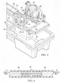
- FIG. 1 and Figure 2A depict the steam based self-contained faux fireplace at 10.
- Fireplace 10 is seen to have a generally elongated and rectangular housing 12 including a cavity 14 including a manifold 16 configured to generate a steam based illuminated faux flame.
- the manifold 16 is situated in the bottom of the cavity 14, and is fed steam by a boiler unit 18 disposed in one end of the fireplace 10 as shown.
- the boiler unit 18 has a low power boiler 20 controlled by control electronics 22.
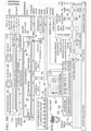
- Control electronics 22 includes a circuit board in boiler unit 18. and a main circuit board as shown (see Figure 9A-1 and 9A-2 ).
- the boiler 20 is a small pressure vessel configured to efficiently produce steam under computer controlled settings, and has reduced power requirements and water consumption. Details of the steam generation system and control electronics are shown in Figure 9A-1 and 9A-2 , and will be described in additional detail shortly.
- the fireplace 10 has a vent assembly 24 at the top of the cavity 14 and configured to selectively vent moisture from within the cavity 14.
- the vent assembly has a pair of fans 26 configured to draw moisture from above the manifold 16 and an outlet 28 thereover configured to vent the drawn moisture to the ambient.
- the fireplace 10 has a retractable glass panel 30 extending across a front side opening of housing 12, and which glass panel 30 can be retracted upward and into the cavity 14 like a garage door upon railings 31 formed in opposing sidewalls 32 to allow access to the manifold 16 and the control electronics 22.
- a rear panel 17 of housing 12 can comprise a solid panel comprised of metal or the like, and may include another glass panel if it is desired to have a see-through fireplace 10.
- a removable interior panel 19 allows access to the boiler unit 18 and boiler 20, control electronics 22, conduits, a water filter, water pump, and other features from within cavity 14.
- the fireplace 10 has a water reservoir 40 formed in the bottom of the housing 12 under the manifold 16 configured to hold water.
- a water pump 42 is configured to controllably draw water from the reservoir 40 via a flexible conduit 44 comprising tubing.
- a water level sensor 43 is positioned in reservoir 40 and provides water level information to control electronics 22 ( Figure 9A-1 and 9A-2 , 9B ).
- a replaceable water filter 45 may be in line with conduit 44 to filter particulates from the water, as shown in Figure 9A-1 and 9A-2 and Figure 9B .
- a conduit 47 routes the drawn water from pump 42 to a first conduit 46 that is integrally and rigidly formed in the elongated manifold 16 along the length of the manifold on a near side. This causes the water in the conduit 46 to heat up by the heated steam emitted by the manifold 16, as will be discussed shortly.
- a flexible conduit 50 receives the partially heated water at the far end of conduit 46, and routes the partially heated water back to a second conduit 52 that is also integrally formed in the elongated manifold 16 and extending along a back and lower side of the manifold 16. This causes the water to be further heated by the steam emitted by the manifold 16.
- a flexible conduit 54 receives the heated water, and routes the heated water via a check valve 56 to the boiler 20.
- the check valve 56 is configured to prevent water returning to the reservoir and maintain steam pressure in the boiler 20.
- the unique routing of the water from the pump 42 along both sides of the manifold forms a pre-heater that heats the water before the water is boiled in the boiler 20.
- This configuration reclaims steam energy from the emission used for the faux flame effect.
- the reclaimed heat increases efficiency, allowing a smaller, efficient boiler 20 to be used as less energy is required to heat the pre-heated water to a boiling temperature of 100 - 130 degrees C, depending on the boiler pressure setting.
- the boiler can be operated on standard 120 VAC, 20 amps as opposed to 240 VAC drawing larger current, and which is not readily available in homes, apartments and the like.
- the total power load of fireplace 10 at any given point in time does not exceed 1920 Watts at 120 VAC, or 1760 Watts at 110 VAC.
- the heated water is provided to the inlet of boiler 20 at a consistent temperature, thus minimizing temperature shock when water is added to the boiler 20. Without this feature, cold water provided to the boiler 20 shocks the boiler 20, knocking down the flame effect provided by manifold 16.
- this pre-heating provides a more consistent flame effect despite variations in water supply temperature.
- the boiler 20 is configured to route the boiled water to a manifold feeder conduit 60 via a flexible conduit 62 and an in-line orifice 64.
- the orifice 64 is configure to regulate and maintain a volume of steam delivered by the boiler 20, and causes the steam to be released at a higher velocity downstream.
- a larger orifice 64 having a larger opening is used when fireplace 10 operating in higher ambient temperatures, and an orifice with a smaller opening is used when operating fireplace 10 in colder ambient temperatures to generate a superior faux flame effect across varying temperatures.
- the orifice 64 can comprise a variable opening orifice controllable by control electronics 22.
- the manifold feeder conduit 60 and conduit 62 are angled slightly downward from the boiler 20 to a t-shaped connector 65 feeding a pair of steam distribution conduits 76.
- the angled conduit 62 directs any liquid in the conduit 62 downwardly such that liquid does not puddle in the conduits 60 and 62. Otherwise, liquid in these conduits could make undesirable sounds, such as a sound imitating a sparking sound.
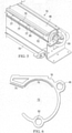
- FIG. 6 A vertical cross section of manifold 16 is shown in Figure 6 , illustrating the manifold 16 having an upper curved interior surface 70 formed over a manifold cavity 72, and extending to a lip 74.
- the pair of steam distribution conduits 76 are configured to loop around the manifold 16 and then extend down the middle of cavity 72, having a plurality of openings 77 configured to release and direct steam upwardly to impinge against the curved interior surface 70.
- Each conduit 76 terminates proximate the other in the middle of manifold 16.
- This curved interior surface 70 advantageously causes the impinging steam to deflect and lose some energy and velocity, and the deflected steam billows outwardly, around lip 74, upwardly.
- This billowing steam is then illuminated by a light source 78 to create a very realistic faux flame 79 in 3 dimensions.
- the light source may be a high intensity white LED light strip with LEDs positioned under a curved lens 84 and arranged to shine through color gel filters, or alternately, may be a multi-colored LED light strip having longitudinally extending orange LED lights 80 and red LED lights 82 positioned under the curved lens 84.
- a plurality of disc-like separators 86 are disposed about conduit 76 along the length of conduit 76, and are spaced to form adjacent pockets within manifold 16 to create a generally uniform release of steam along the length of the manifold 16. Any moisture that returns to the liquid state drips back into reservoir 40, to create a self-draining steam delivery network.
- the billowing steam emitted by the manifold 16 preheats the water circulating though integral conduits 46 and 52, thereby using reclaimed steam energy from steam emission used for the faux flame effect. The reclaimed heat increases efficiency, thus enabling a lower power solution operable from 120 VAC instead of 240 VAC.
- Fire bed media may be provided over manifold 16, and may include fire bed illumination.
- the fire bed illumination may include user adjustable RGB LED lighting for special effects illumination of the fire bed media.
- the fire bed lighting functions regardless of whether the fireplace 10 is on or off, to allow use as mood/ambience lighting.
- Fire bed media shall be lit completely and evenly in front and along both sides of the faux flame. No lighting is provided for the media bed area behind the faux flame 79.
- the LED light 78 running the length of the front and sides of the faux flame 79 provides the necessary illumination.
- Faux logs may be placed on top of the fire bed media, and/or over the manifold 16.
- Faux log lighting may be provided operating at approximately 5 Watts.
- Firmware controls automatically vary the intensity of the faux log lighting per a control algorithm to generate a realistic "glowing" effect when the faux flame 79 is active.
- the control electronics 22 determines the steam pressure in boiler 20 by first sensing the temperature of the boiler 20 housing using temperature sensor 85.
- Boiler unit 18 has a boiler auto-fill mechanism.
- the control electronics 22 on the steam subsystem circuit board 90 ( Figure 9A) utilizes a water level sensor to inject varying quantities of water into the boiler 20, via commands to the pump 42, minimizing the shock to the boiler 20 and thus maintaining a consistent faux flame 79 effect. Volume and timing of water injection into boiler 20 is determined based on calculated steam emission rate and the timing of the power applied to the boiler 20.
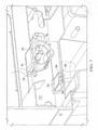
- a purge valve 86 is coupled to a bottom of the boiler 20, and is configured to purge water and steam from the boiler 20 upon receipt of a purge signal received from control electronics 22.
- the purge valve 86 may be a solenoid driven valve, although other types of controllable valves are acceptable.
- the purge valve 86 remove any particulates, such as sediment, that may build up on the bottom of the boiler 20 due to the violent release of water and steam and the reduction of pressure. This advantageously extends the mean time between failure (MTBF) of the boiler 20.
- the purge valve 86 also helps shut down the boiler quickly when controlled by the control electronics 22, and complete a shut down cycle.
- control electronics 22 is seen to comprise a steam subsystem circuit board 90 controlling the boiler unit 18 including boiler 20, and a main controller board 92 including a microcontroller 94 that controls fireplace 10, including the circuit board 90 via communications interface 96.
- the control electronics 22 controls various functions of the fireplace 10, and has a hardwired user interface 98 including a keypad and a display coupled to the control electronics 22 allowing a user to select functions and control the fireplace 10.
- a wireless remote control 100 ( Figure 2B and Figure 9B ) is configured to communicate with the microcontroller 94 via an infrared (IR) transceivers 102.
- the microcontroller 94 monitors fireplace 10 in real-time.
- the main controller (MC) circuit board 92 implements the user interface 98, supervisory functions, and wireless connectivity functions for the fireplace.
- the total power available to MC circuit board 92 is approximately 5 Watts, and includes sufficient non-volatile memory to allow saving of user settings.
- the MC circuit board 92 includes a real-time clock (RTC) function that allows tracking of accumulated runtime hours and water filter replacement scheduling.
- RTC real-time clock
- Microcontroller 94 controls the height of the faux flame 79 via circuit board 90 by sensing the housing temperature T of boiler 20 using thermostat 85 and controlling the power delivered to heater coils 104 formed in the bottom of the boiler 20 via conductors 106.
- the power is regulated by microcontroller 94 to vary pressure in the boiler 20, and thus the height of the faux flame 79.
- a preferred method is based on zero cross switching. More power creates higher boiler pressure and a higher faux flame 79, and less power creates a lower boiler pressure and a lower faux flame 79. Typical boiler operating pressures range between about 8-30 psi, and typically no greater than 25 psi.
- the user uses the user interface 98 or remote control 100 to command the microcontroller 94 to vary faux flame 79 height.
- the fans 26 create some upwardly directed air flow to help keep moisture from accumulating on the glass panel 30, even at the highest faux flame 79 level.
- Microcontroller 94 provides autosensing for automatic control and adjustment of the faux flame 79.
- Microcontroller 94 senses major variables that affect the quality of the faux flame 79, including ambient temperature via temperature probe 110, ambient humidity, and manifold temperature.
- the real-time microcontroller 94 provides for automatic adjustment of the pressurized boiler unit 18 for the faux fire effect, thus enabling a consistent faux flame 79 for varying conditions.
- Fireplace 10 includes an auxiliary heater 112 configured to generate heat and augment the heat produced by the steam emitted from manifold 16. Power to the heater 112 is provided via conductors 114 and is controlled by microcontroller 94, which is also controllable by the user via the user interface 98 and/or remote control 100.
- the auxiliary heater 112 uses a dedicated 20 Amp branch circuit separate from the rest of the fireplace 10 power, and the heater does not draw more than 16 Amps.
- the optional auxiliary heater assembly includes its own dedicated thermal safety cutoff switch located adjacent to the heater assembly.
- the thermal safety switch senses if the enclosure exceeds 162 degrees F (72 C).
- a thermal safety switch interrupts power to the auxiliary heater.
- the thermal switch is resettable type and serviceable.
- the fireplace has a water leak sensor 114.
- Sensor 114 is mounted in the bottom reservoir such that the unexpected presence of water triggers an audio alarm.
- the MC circuit board 92 enters Service Mode, displaying the "Contact Service” screen and the fault code associated with a leak.
- control electronics 22 including microcontroller 94 control and operate the fireplace 10 using the operational flowchart (algorithm) 120 shown.
- Warm-up time of fireplace 20 from a standby mode to a ready mode is 1-3 minutes depending on the power up conditions.
- the fireplace 10 provides as standard, a user display, a manual keypad interface and a wireless remote control interface 100.
- An industry standard form factor custom 4.3" LCD display 98 is mounted in a recessed location in the lower right hand corner in front of the glass firebox viewing window ( Figure 2B ).
- the user display 98 functions per the operational flowchart 120 ( Figure 11 ) with features as follows:
- a tact switch user interface keypad with the arrangement as shown in Figure 12 , is located at the bottom right of the Viewing Window frame.
- a simple custom Infrared-type remote 100 is provided.
- the remote control 100 implements the same functionality as the keypad and provides for wireless same room direct line-of-sight fireplace operation.
Landscapes
- Engineering & Computer Science (AREA)
- General Engineering & Computer Science (AREA)
- Chemical & Material Sciences (AREA)
- Combustion & Propulsion (AREA)
- Mechanical Engineering (AREA)
- Thermal Sciences (AREA)
- Physics & Mathematics (AREA)
- Sustainable Development (AREA)
- Sustainable Energy (AREA)
- Life Sciences & Earth Sciences (AREA)
- Drying Of Solid Materials (AREA)
- Steam Or Hot-Water Central Heating Systems (AREA)
- Control Of Steam Boilers And Waste-Gas Boilers (AREA)
- Electric Stoves And Ranges (AREA)
- Induction Heating Cooking Devices (AREA)
Claims (9)
- Kamin-Imitat (10) auf Dampfbasis, umfassend:ein Reservoir (40), das dazu konfiguriert ist, ein Fluid zu halten;einen Verteiler (16) mit einem ersten Eingang, der dazu konfiguriert ist, das Fluid von dem Reservoir (40) aufzunehmen, und einem ersten Ausgang, wobei der Verteiler eine erste Leitung (46) aufweist, die sich von dem ersten Eingang zu dem ersten Ausgang erstreckt, so dass Wärme von dem Verteiler (16) mit dem Fluid, das durch die erste Leitung (46) übertragen wird, gekoppelt wird;einen Erhitzer (20), der dazu konfiguriert ist, das Fluid von dem ersten Ausgang aufzunehmen, wobei der Erhitzer dazu konfiguriert ist, das Fluid zu erhitzen und Dampf zu erzeugen; undwobei der Verteiler (16) einen zweiten Eingang aufweist, der dazu konfiguriert ist, den Dampf von dem Erhitzer aufzunehmen, wobei der Verteiler eine zweite Leitung (52) aufweist, die sich von dem zweiten Eingang zu dem zweiten Ausgang erstreckt, wobei der zweite Ausgang dazu konfiguriert ist, den Dampf auszustoßen und zudem den ausgestoßenen Dampf zu lenken.
- Kamin-Imitat auf Dampfbasis nach Anspruch 1, wobei der Verteiler (16) länglich ist und die erste Leitung (46) sich entlang einer Länge des Verteilers erstreckt.
- Kamin-Imitat auf Dampfbasis nach Anspruch 2, wobei die erste Leitung (46) sich von einem ersten Ende des Verteilers zu einem entgegengesetzten zweiten Ende des Verteilers und dann zurück von dem zweiten Ende zu dem ersten Ende erstreckt.
- Kamin-Imitat auf Dampfbasis nach Anspruch 1, wobei der zweite Verteilereingang nahe einem Mittelteil des Verteilers ist, weiterhin umfassend einen ersten Durchtritt (76), der sich von dem zweiten Eingang zu einem ersten Verteilerende erstreckt, und einen zweiten Durchtritt (76), der sich von dem zweiten Eingang zu einem entgegengesetzten zweiten Ende des Verteilers erstreckt.
- Kamin-Imitat auf Dampfbasis nach Anspruch 4, weiterhin umfassend einen dritten Durchtritt (60, 62), der sich zwischen dem Erhitzer (20) und dem zweiten Verteilereingang erstreckt, wobei der dritte Durchtritt (60, 62) sich nach oben von dem zweiten Verteilereingang erstreckt, so dass Flüssigkeit sich nicht in dem dritten Durchtritt ansammelt.
- Kamin-Imitat auf Dampfbasis nach Anspruch 1, wobei der Verteiler (16) aus einem wärmeleitenden Material besteht.
- Kamin-Imitat auf Dampfbasis nach Anspruch 6, wobei die Leitung (46) integral mit dem Verteiler (16) ausgebildet ist.
- Kamin-Imitat auf Dampfbasis nach Anspruch 1, weiterhin umfassend einen Ableiter (70), der gegenüber dem zweiten Verteilerausgang positioniert ist und dazu konfiguriert ist, den gelenkten abgegebenen Dampf von dem Verteiler aufzunehmen, so dass der Dampf um den Ableiter wabert.
- Kamin-Imitat auf Dampfbasis nach Anspruch 8, wobei der Ableiter (70) physisch mit dem Verteiler verbunden ist.
Priority Applications (1)
| Application Number | Priority Date | Filing Date | Title |
|---|---|---|---|
| EP19194794.4A EP3614052A1 (de) | 2017-01-09 | 2017-11-06 | Falscher kamin auf dampfbasis |
Applications Claiming Priority (3)
| Application Number | Priority Date | Filing Date | Title |
|---|---|---|---|
| US201762444073P | 2017-01-09 | 2017-01-09 | |
| US15/497,694 US10393385B2 (en) | 2017-01-09 | 2017-04-26 | Steam based faux fireplace |
| PCT/US2017/060156 WO2018128700A1 (en) | 2017-01-09 | 2017-11-06 | Steam based faux fireplace |
Related Child Applications (2)
| Application Number | Title | Priority Date | Filing Date |
|---|---|---|---|
| EP19194794.4A Division-Into EP3614052A1 (de) | 2017-01-09 | 2017-11-06 | Falscher kamin auf dampfbasis |
| EP19194794.4A Division EP3614052A1 (de) | 2017-01-09 | 2017-11-06 | Falscher kamin auf dampfbasis |
Publications (2)
| Publication Number | Publication Date |
|---|---|
| EP3566005A1 EP3566005A1 (de) | 2019-11-13 |
| EP3566005B1 true EP3566005B1 (de) | 2022-01-19 |
Family
ID=62750236
Family Applications (2)
| Application Number | Title | Priority Date | Filing Date |
|---|---|---|---|
| EP17801207.6A Active EP3566005B1 (de) | 2017-01-09 | 2017-11-06 | Dampfbasierte künstliche feuerstätte |
| EP19194794.4A Withdrawn EP3614052A1 (de) | 2017-01-09 | 2017-11-06 | Falscher kamin auf dampfbasis |
Family Applications After (1)
| Application Number | Title | Priority Date | Filing Date |
|---|---|---|---|
| EP19194794.4A Withdrawn EP3614052A1 (de) | 2017-01-09 | 2017-11-06 | Falscher kamin auf dampfbasis |
Country Status (5)
| Country | Link |
|---|---|
| US (3) | US10393385B2 (de) |
| EP (2) | EP3566005B1 (de) |
| CN (2) | CN110657484B (de) |
| CA (2) | CA3073243C (de) |
| WO (1) | WO2018128700A1 (de) |
Families Citing this family (10)
| Publication number | Priority date | Publication date | Assignee | Title |
|---|---|---|---|---|
| US10994219B2 (en) * | 2017-11-13 | 2021-05-04 | Technifex, Inc. | Simulated fire effect using steam |
| CA3023901C (en) * | 2017-11-13 | 2021-01-12 | Technifex, Inc. | Apparatus for producing a fire special effect |
| JP7063460B2 (ja) * | 2018-08-30 | 2022-05-09 | 株式会社ひよ子 | 蒸気加温ユニット、蒸気加温方法、菓子製造装置及び菓子製造方法 |
| US11867409B2 (en) | 2019-09-24 | 2024-01-09 | Greentouch USA, Inc. | Modular assembly for electric fireplace |
| US11619390B2 (en) | 2019-09-24 | 2023-04-04 | Greentouch USA, Inc. | Modular assembly for electric fireplace |
| US12392494B2 (en) | 2019-09-24 | 2025-08-19 | Greentouch USA, Inc. | Modular assembly for electric fireplace |
| US20210204582A1 (en) * | 2020-01-06 | 2021-07-08 | Dennis Wysocki | Herbal decarboxylation and infusion system |
| US12491135B2 (en) * | 2020-01-06 | 2025-12-09 | Dennis Wysocki | Herbal decarboxylation and infusion system |
| CA3220336A1 (en) * | 2021-05-25 | 2022-12-01 | Matthew Alfred CROWE | Modular assembly for electric fireplace |
| USD1112663S1 (en) * | 2024-07-26 | 2026-02-10 | Min-Hsun Lu | Heater for electric fireplace |
Family Cites Families (33)
| Publication number | Priority date | Publication date | Assignee | Title |
|---|---|---|---|---|
| US3069794A (en) * | 1959-08-31 | 1962-12-25 | Stalcup Inc | Steam emitting sign apparatus |
| US3273542A (en) * | 1964-05-19 | 1966-09-20 | Riley Stoker Corp | Steam generating unit |
| US3432439A (en) * | 1967-01-09 | 1969-03-11 | Missouri Research Lab Inc | Smoke generating apparatus |
| US4058107A (en) * | 1976-07-01 | 1977-11-15 | Norwich Laboratory, Inc. | Combination isobaric steam-heater and enclosure for use with fireplaces |
| US4137896A (en) * | 1977-06-23 | 1979-02-06 | Sunbeam Corporation | Fireplace enclosure and heat-exchanger unit |
| NL8201276A (nl) * | 1982-03-26 | 1983-10-17 | Gerardus Hubertus Paulus Wilhe | Haardkachel. |
| FR2529995A1 (fr) * | 1982-07-12 | 1984-01-13 | Fabre Sar Fonderie | Chaudiere d'atre |
| US4439341A (en) * | 1983-03-21 | 1984-03-27 | The United States Of America As Represented By The Secretary Of The Navy | Smoke generator for use with water and smoke generant |
| FR2567625A1 (fr) * | 1984-07-13 | 1986-01-17 | Nardulli Gaetan | Recuperateur de chaleur a circulation d'eau |
| CA1219545A (en) * | 1984-12-06 | 1987-03-24 | Glen Sundquist | Water heater and distiller apparatus |
| US5989128A (en) * | 1998-01-08 | 1999-11-23 | Universal Studios, Inc. | Flame simulation |
| US6168531B1 (en) * | 1999-06-15 | 2001-01-02 | Sony Corporation | Soup bowl attraction |
| GB0202152D0 (en) | 2002-01-30 | 2002-03-20 | Valor Ltd | Smoke effect apparatus |
| US7762897B2 (en) * | 2002-04-04 | 2010-07-27 | Technifex, Inc. | Apparatus for producing a fire special effect |
| US6685574B2 (en) * | 2002-04-04 | 2004-02-03 | Technifex, Inc. | Apparatus for producing a fire special effect using steam |
| DE10330681B3 (de) * | 2003-03-26 | 2004-06-24 | Ionto-Comed Gmbh | Gerät zur Kräuterbedampfung |
| GB2418014B (en) * | 2004-09-10 | 2009-05-06 | Basic Holdings | Apparatus for producing an optical effect |
| GB0605001D0 (en) | 2006-03-13 | 2006-04-19 | Basic Holdings | Fuel and flame effect fires |
| GB0603314D0 (en) * | 2006-02-20 | 2006-03-29 | Sun Brian | Steam Generator |
| US7832364B2 (en) * | 2006-12-14 | 2010-11-16 | Texaco Inc. | Heat transfer unit for steam generation and gas preheating |
| GB0717770D0 (en) * | 2007-09-12 | 2007-10-24 | Basic Holdings | Electric fire |
| GB2455277B (en) | 2007-09-12 | 2013-01-23 | Basic Holdings | Electric fire |
| GB2460453B (en) * | 2008-05-30 | 2011-03-09 | Basic Holdings | Electric fire |
| US20100031543A1 (en) * | 2008-08-05 | 2010-02-11 | James Rice | Systems for faux wood burning heating apparatuses, faux wood burning heating apparatuses and inserts for faux wood burning heating apparatuses producing realistic looking faux fire effects, and methods of emulating a wood burning heating apparatus |
| US20100237156A1 (en) * | 2009-03-17 | 2010-09-23 | Minogue James D | Heating system and method using a fireplace |
| AU2011265435B2 (en) * | 2010-12-29 | 2014-04-24 | Bissell Inc. | Cleaning implement with mist generating system |
| ES2435615B1 (es) * | 2012-03-22 | 2014-09-10 | Luis RUIZ BARBERO | Tubo de evacuacion de humos y gases para estufas, calderas y chimeneas, con aprovechamiento del calor residual desprendido en la combustion |
| GB2502077B (en) * | 2012-05-15 | 2016-04-06 | Basic Holdings | A simulated flame effect fire |
| WO2014093810A2 (en) * | 2012-12-14 | 2014-06-19 | A & T Creative Workshop Inc. | Portable apparatus and method for producing a simulated flame effect |
| US20160195277A1 (en) * | 2015-01-07 | 2016-07-07 | Zhongshan City Shende Electrical Appliance Ltd. | Simulation electric fireplace having mist, humidifying and heating functions |
| CN104748199B (zh) | 2015-03-31 | 2018-11-09 | 东莞崧崴电子科技有限公司 | 具有喷雾观赏及加湿多功能的取暖器 |
| US20170095105A1 (en) * | 2015-10-05 | 2017-04-06 | Joseph R. Clark | Mini steam generator for cooking food, modular cooking appliance, and modular food preparation station |
| US9709282B1 (en) * | 2016-08-08 | 2017-07-18 | Afc (Alex Fireplace Company) Limited | Device for simulating a flame effect |
-
2017
- 2017-04-26 US US15/497,694 patent/US10393385B2/en active Active
- 2017-08-25 US US15/687,284 patent/US10018362B1/en active Active
- 2017-11-06 WO PCT/US2017/060156 patent/WO2018128700A1/en not_active Ceased
- 2017-11-06 EP EP17801207.6A patent/EP3566005B1/de active Active
- 2017-11-06 EP EP19194794.4A patent/EP3614052A1/de not_active Withdrawn
- 2017-11-06 CA CA3073243A patent/CA3073243C/en active Active
- 2017-11-06 CA CA3055173A patent/CA3055173C/en active Active
- 2017-12-04 CN CN201910977861.8A patent/CN110657484B/zh not_active Expired - Fee Related
- 2017-12-04 CN CN201711261053.9A patent/CN108286731B9/zh not_active Expired - Fee Related
-
2019
- 2019-08-23 US US16/549,159 patent/US11054141B2/en active Active
Non-Patent Citations (1)
| Title |
|---|
| None * |
Also Published As
| Publication number | Publication date |
|---|---|
| US10393385B2 (en) | 2019-08-27 |
| CN110657484B (zh) | 2021-02-02 |
| US20190376693A1 (en) | 2019-12-12 |
| US20180195731A1 (en) | 2018-07-12 |
| WO2018128700A1 (en) | 2018-07-12 |
| US20180195730A1 (en) | 2018-07-12 |
| CA3073243C (en) | 2020-07-14 |
| EP3566005A1 (de) | 2019-11-13 |
| CN108286731A (zh) | 2018-07-17 |
| CA3055173A1 (en) | 2018-07-12 |
| CN110657484A (zh) | 2020-01-07 |
| CA3055173C (en) | 2020-09-01 |
| US11054141B2 (en) | 2021-07-06 |
| CN108286731B (zh) | 2020-08-14 |
| CN108286731B9 (zh) | 2022-03-01 |
| CA3073243A1 (en) | 2018-07-12 |
| EP3614052A1 (de) | 2020-02-26 |
| US10018362B1 (en) | 2018-07-10 |
Similar Documents
| Publication | Publication Date | Title |
|---|---|---|
| US11054141B2 (en) | Steam based faux fireplace | |
| US10145562B1 (en) | Steam based faux fireplace | |
| US5738084A (en) | Ventless patio fireplace | |
| US5470018A (en) | Thermostatically controlled gas heater | |
| US10015655B2 (en) | Smart patio heater device | |
| US20210285661A1 (en) | Heating and cooling appliance | |
| CA3154870C (en) | Hybrid residential heater and control system therefor | |
| US8141788B2 (en) | Thermostatic control device | |
| US8931707B2 (en) | Appliance with thermostatic controls | |
| CN106068426A (zh) | 加热系统 | |
| EP3096084B1 (de) | Kaminheizkessel | |
| CN214148052U (zh) | 一种集成灶的送风系统及集成灶 | |
| WO2023194774A1 (en) | Smart heater gadget with the capability of heating and filtering the environment's air | |
| CN219797327U (zh) | 一种具有保护电路的电壁炉 | |
| CN108884994A (zh) | 具有可变火焰速率的雾化燃烧器 | |
| JP2002048412A (ja) | 燃焼式暖房機 | |
| JP3621281B2 (ja) | 液体燃焼器における燃料供給装置 | |
| JP4165986B2 (ja) | 開放燃焼式暖房機 | |
| JP2002048411A (ja) | 燃焼式暖房機 | |
| GB2479574A (en) | Electric fire also burning a fluid fuel to generate flames | |
| CN112503597A (zh) | 一种集成灶的送风系统及集成灶 | |
| KR20110006783A (ko) | 보일러의 기능을 갖는 난로 | |
| JP2002039626A (ja) | 燃焼式暖房機 | |
| JPH04218318A (ja) | 圧縮エアー加熱による伝導熱源使用方法 | |
| JP2016114306A (ja) | 暖房装置 |
Legal Events
| Date | Code | Title | Description |
|---|---|---|---|
| STAA | Information on the status of an ep patent application or granted ep patent |
Free format text: STATUS: UNKNOWN |
|
| STAA | Information on the status of an ep patent application or granted ep patent |
Free format text: STATUS: THE INTERNATIONAL PUBLICATION HAS BEEN MADE |
|
| PUAI | Public reference made under article 153(3) epc to a published international application that has entered the european phase |
Free format text: ORIGINAL CODE: 0009012 |
|
| STAA | Information on the status of an ep patent application or granted ep patent |
Free format text: STATUS: REQUEST FOR EXAMINATION WAS MADE |
|
| 17P | Request for examination filed |
Effective date: 20190809 |
|
| AK | Designated contracting states |
Kind code of ref document: A1 Designated state(s): AL AT BE BG CH CY CZ DE DK EE ES FI FR GB GR HR HU IE IS IT LI LT LU LV MC MK MT NL NO PL PT RO RS SE SI SK SM TR |
|
| AX | Request for extension of the european patent |
Extension state: BA ME |
|
| DAV | Request for validation of the european patent (deleted) | ||
| DAX | Request for extension of the european patent (deleted) | ||
| STAA | Information on the status of an ep patent application or granted ep patent |
Free format text: STATUS: EXAMINATION IS IN PROGRESS |
|
| 17Q | First examination report despatched |
Effective date: 20200710 |
|
| GRAP | Despatch of communication of intention to grant a patent |
Free format text: ORIGINAL CODE: EPIDOSNIGR1 |
|
| STAA | Information on the status of an ep patent application or granted ep patent |
Free format text: STATUS: GRANT OF PATENT IS INTENDED |
|
| INTG | Intention to grant announced |
Effective date: 20210728 |
|
| GRAS | Grant fee paid |
Free format text: ORIGINAL CODE: EPIDOSNIGR3 |
|
| GRAA | (expected) grant |
Free format text: ORIGINAL CODE: 0009210 |
|
| STAA | Information on the status of an ep patent application or granted ep patent |
Free format text: STATUS: THE PATENT HAS BEEN GRANTED |
|
| AK | Designated contracting states |
Kind code of ref document: B1 Designated state(s): AL AT BE BG CH CY CZ DE DK EE ES FI FR GB GR HR HU IE IS IT LI LT LU LV MC MK MT NL NO PL PT RO RS SE SI SK SM TR |
|
| REG | Reference to a national code |
Ref country code: GB Ref legal event code: FG4D |
|
| REG | Reference to a national code |
Ref country code: CH Ref legal event code: EP |
|
| REG | Reference to a national code |
Ref country code: DE Ref legal event code: R096 Ref document number: 602017052545 Country of ref document: DE |
|
| REG | Reference to a national code |
Ref country code: AT Ref legal event code: REF Ref document number: 1464009 Country of ref document: AT Kind code of ref document: T Effective date: 20220215 |
|
| REG | Reference to a national code |
Ref country code: IE Ref legal event code: FG4D |
|
| REG | Reference to a national code |
Ref country code: LT Ref legal event code: MG9D |
|
| REG | Reference to a national code |
Ref country code: NL Ref legal event code: MP Effective date: 20220119 |
|
| REG | Reference to a national code |
Ref country code: AT Ref legal event code: MK05 Ref document number: 1464009 Country of ref document: AT Kind code of ref document: T Effective date: 20220119 |
|
| PG25 | Lapsed in a contracting state [announced via postgrant information from national office to epo] |
Ref country code: NL Free format text: LAPSE BECAUSE OF FAILURE TO SUBMIT A TRANSLATION OF THE DESCRIPTION OR TO PAY THE FEE WITHIN THE PRESCRIBED TIME-LIMIT Effective date: 20220119 |
|
| PG25 | Lapsed in a contracting state [announced via postgrant information from national office to epo] |
Ref country code: SE Free format text: LAPSE BECAUSE OF FAILURE TO SUBMIT A TRANSLATION OF THE DESCRIPTION OR TO PAY THE FEE WITHIN THE PRESCRIBED TIME-LIMIT Effective date: 20220119 Ref country code: RS Free format text: LAPSE BECAUSE OF FAILURE TO SUBMIT A TRANSLATION OF THE DESCRIPTION OR TO PAY THE FEE WITHIN THE PRESCRIBED TIME-LIMIT Effective date: 20220119 Ref country code: PT Free format text: LAPSE BECAUSE OF FAILURE TO SUBMIT A TRANSLATION OF THE DESCRIPTION OR TO PAY THE FEE WITHIN THE PRESCRIBED TIME-LIMIT Effective date: 20220519 Ref country code: NO Free format text: LAPSE BECAUSE OF FAILURE TO SUBMIT A TRANSLATION OF THE DESCRIPTION OR TO PAY THE FEE WITHIN THE PRESCRIBED TIME-LIMIT Effective date: 20220419 Ref country code: LT Free format text: LAPSE BECAUSE OF FAILURE TO SUBMIT A TRANSLATION OF THE DESCRIPTION OR TO PAY THE FEE WITHIN THE PRESCRIBED TIME-LIMIT Effective date: 20220119 Ref country code: HR Free format text: LAPSE BECAUSE OF FAILURE TO SUBMIT A TRANSLATION OF THE DESCRIPTION OR TO PAY THE FEE WITHIN THE PRESCRIBED TIME-LIMIT Effective date: 20220119 Ref country code: ES Free format text: LAPSE BECAUSE OF FAILURE TO SUBMIT A TRANSLATION OF THE DESCRIPTION OR TO PAY THE FEE WITHIN THE PRESCRIBED TIME-LIMIT Effective date: 20220119 Ref country code: BG Free format text: LAPSE BECAUSE OF FAILURE TO SUBMIT A TRANSLATION OF THE DESCRIPTION OR TO PAY THE FEE WITHIN THE PRESCRIBED TIME-LIMIT Effective date: 20220419 |
|
| PG25 | Lapsed in a contracting state [announced via postgrant information from national office to epo] |
Ref country code: PL Free format text: LAPSE BECAUSE OF FAILURE TO SUBMIT A TRANSLATION OF THE DESCRIPTION OR TO PAY THE FEE WITHIN THE PRESCRIBED TIME-LIMIT Effective date: 20220119 Ref country code: LV Free format text: LAPSE BECAUSE OF FAILURE TO SUBMIT A TRANSLATION OF THE DESCRIPTION OR TO PAY THE FEE WITHIN THE PRESCRIBED TIME-LIMIT Effective date: 20220119 Ref country code: GR Free format text: LAPSE BECAUSE OF FAILURE TO SUBMIT A TRANSLATION OF THE DESCRIPTION OR TO PAY THE FEE WITHIN THE PRESCRIBED TIME-LIMIT Effective date: 20220420 Ref country code: FI Free format text: LAPSE BECAUSE OF FAILURE TO SUBMIT A TRANSLATION OF THE DESCRIPTION OR TO PAY THE FEE WITHIN THE PRESCRIBED TIME-LIMIT Effective date: 20220119 Ref country code: AT Free format text: LAPSE BECAUSE OF FAILURE TO SUBMIT A TRANSLATION OF THE DESCRIPTION OR TO PAY THE FEE WITHIN THE PRESCRIBED TIME-LIMIT Effective date: 20220119 |
|
| PG25 | Lapsed in a contracting state [announced via postgrant information from national office to epo] |
Ref country code: IS Free format text: LAPSE BECAUSE OF FAILURE TO SUBMIT A TRANSLATION OF THE DESCRIPTION OR TO PAY THE FEE WITHIN THE PRESCRIBED TIME-LIMIT Effective date: 20220519 |
|
| REG | Reference to a national code |
Ref country code: DE Ref legal event code: R097 Ref document number: 602017052545 Country of ref document: DE |
|
| PG25 | Lapsed in a contracting state [announced via postgrant information from national office to epo] |
Ref country code: SM Free format text: LAPSE BECAUSE OF FAILURE TO SUBMIT A TRANSLATION OF THE DESCRIPTION OR TO PAY THE FEE WITHIN THE PRESCRIBED TIME-LIMIT Effective date: 20220119 Ref country code: SK Free format text: LAPSE BECAUSE OF FAILURE TO SUBMIT A TRANSLATION OF THE DESCRIPTION OR TO PAY THE FEE WITHIN THE PRESCRIBED TIME-LIMIT Effective date: 20220119 Ref country code: RO Free format text: LAPSE BECAUSE OF FAILURE TO SUBMIT A TRANSLATION OF THE DESCRIPTION OR TO PAY THE FEE WITHIN THE PRESCRIBED TIME-LIMIT Effective date: 20220119 Ref country code: EE Free format text: LAPSE BECAUSE OF FAILURE TO SUBMIT A TRANSLATION OF THE DESCRIPTION OR TO PAY THE FEE WITHIN THE PRESCRIBED TIME-LIMIT Effective date: 20220119 Ref country code: DK Free format text: LAPSE BECAUSE OF FAILURE TO SUBMIT A TRANSLATION OF THE DESCRIPTION OR TO PAY THE FEE WITHIN THE PRESCRIBED TIME-LIMIT Effective date: 20220119 Ref country code: CZ Free format text: LAPSE BECAUSE OF FAILURE TO SUBMIT A TRANSLATION OF THE DESCRIPTION OR TO PAY THE FEE WITHIN THE PRESCRIBED TIME-LIMIT Effective date: 20220119 |
|
| PLBE | No opposition filed within time limit |
Free format text: ORIGINAL CODE: 0009261 |
|
| STAA | Information on the status of an ep patent application or granted ep patent |
Free format text: STATUS: NO OPPOSITION FILED WITHIN TIME LIMIT |
|
| PG25 | Lapsed in a contracting state [announced via postgrant information from national office to epo] |
Ref country code: AL Free format text: LAPSE BECAUSE OF FAILURE TO SUBMIT A TRANSLATION OF THE DESCRIPTION OR TO PAY THE FEE WITHIN THE PRESCRIBED TIME-LIMIT Effective date: 20220119 |
|
| 26N | No opposition filed |
Effective date: 20221020 |
|
| PG25 | Lapsed in a contracting state [announced via postgrant information from national office to epo] |
Ref country code: SI Free format text: LAPSE BECAUSE OF FAILURE TO SUBMIT A TRANSLATION OF THE DESCRIPTION OR TO PAY THE FEE WITHIN THE PRESCRIBED TIME-LIMIT Effective date: 20220119 |
|
| PG25 | Lapsed in a contracting state [announced via postgrant information from national office to epo] |
Ref country code: MC Free format text: LAPSE BECAUSE OF FAILURE TO SUBMIT A TRANSLATION OF THE DESCRIPTION OR TO PAY THE FEE WITHIN THE PRESCRIBED TIME-LIMIT Effective date: 20220119 |
|
| REG | Reference to a national code |
Ref country code: CH Ref legal event code: PL |
|
| REG | Reference to a national code |
Ref country code: BE Ref legal event code: MM Effective date: 20221130 |
|
| PG25 | Lapsed in a contracting state [announced via postgrant information from national office to epo] |
Ref country code: LI Free format text: LAPSE BECAUSE OF NON-PAYMENT OF DUE FEES Effective date: 20221130 Ref country code: IT Free format text: LAPSE BECAUSE OF FAILURE TO SUBMIT A TRANSLATION OF THE DESCRIPTION OR TO PAY THE FEE WITHIN THE PRESCRIBED TIME-LIMIT Effective date: 20220119 Ref country code: CH Free format text: LAPSE BECAUSE OF NON-PAYMENT OF DUE FEES Effective date: 20221130 |
|
| PG25 | Lapsed in a contracting state [announced via postgrant information from national office to epo] |
Ref country code: LU Free format text: LAPSE BECAUSE OF NON-PAYMENT OF DUE FEES Effective date: 20221106 |
|
| PG25 | Lapsed in a contracting state [announced via postgrant information from national office to epo] |
Ref country code: IE Free format text: LAPSE BECAUSE OF NON-PAYMENT OF DUE FEES Effective date: 20221106 |
|
| PG25 | Lapsed in a contracting state [announced via postgrant information from national office to epo] |
Ref country code: FR Free format text: LAPSE BECAUSE OF NON-PAYMENT OF DUE FEES Effective date: 20221130 Ref country code: BE Free format text: LAPSE BECAUSE OF NON-PAYMENT OF DUE FEES Effective date: 20221130 |
|
| PGFP | Annual fee paid to national office [announced via postgrant information from national office to epo] |
Ref country code: DE Payment date: 20231129 Year of fee payment: 7 |
|
| PG25 | Lapsed in a contracting state [announced via postgrant information from national office to epo] |
Ref country code: HU Free format text: LAPSE BECAUSE OF FAILURE TO SUBMIT A TRANSLATION OF THE DESCRIPTION OR TO PAY THE FEE WITHIN THE PRESCRIBED TIME-LIMIT; INVALID AB INITIO Effective date: 20171106 |
|
| PG25 | Lapsed in a contracting state [announced via postgrant information from national office to epo] |
Ref country code: CY Free format text: LAPSE BECAUSE OF FAILURE TO SUBMIT A TRANSLATION OF THE DESCRIPTION OR TO PAY THE FEE WITHIN THE PRESCRIBED TIME-LIMIT Effective date: 20220119 |
|
| PG25 | Lapsed in a contracting state [announced via postgrant information from national office to epo] |
Ref country code: MK Free format text: LAPSE BECAUSE OF FAILURE TO SUBMIT A TRANSLATION OF THE DESCRIPTION OR TO PAY THE FEE WITHIN THE PRESCRIBED TIME-LIMIT Effective date: 20220119 |
|
| PG25 | Lapsed in a contracting state [announced via postgrant information from national office to epo] |
Ref country code: MT Free format text: LAPSE BECAUSE OF FAILURE TO SUBMIT A TRANSLATION OF THE DESCRIPTION OR TO PAY THE FEE WITHIN THE PRESCRIBED TIME-LIMIT Effective date: 20220119 |
|
| PGFP | Annual fee paid to national office [announced via postgrant information from national office to epo] |
Ref country code: GB Payment date: 20241127 Year of fee payment: 8 |
|
| REG | Reference to a national code |
Ref country code: DE Ref legal event code: R119 Ref document number: 602017052545 Country of ref document: DE |
|
| PG25 | Lapsed in a contracting state [announced via postgrant information from national office to epo] |
Ref country code: DE Free format text: LAPSE BECAUSE OF NON-PAYMENT OF DUE FEES Effective date: 20250603 |
|
| PG25 | Lapsed in a contracting state [announced via postgrant information from national office to epo] |
Ref country code: TR Free format text: LAPSE BECAUSE OF FAILURE TO SUBMIT A TRANSLATION OF THE DESCRIPTION OR TO PAY THE FEE WITHIN THE PRESCRIBED TIME-LIMIT Effective date: 20220119 |