EP3565379B1 - Induction device - Google Patents
Induction device Download PDFInfo
- Publication number
- EP3565379B1 EP3565379B1 EP19168843.1A EP19168843A EP3565379B1 EP 3565379 B1 EP3565379 B1 EP 3565379B1 EP 19168843 A EP19168843 A EP 19168843A EP 3565379 B1 EP3565379 B1 EP 3565379B1
- Authority
- EP
- European Patent Office
- Prior art keywords
- induction
- induction element
- current
- operating state
- control unit
- Prior art date
- Legal status (The legal status is an assumption and is not a legal conclusion. Google has not performed a legal analysis and makes no representation as to the accuracy of the status listed.)
- Active
Links
- 230000006698 induction Effects 0.000 title claims description 349
- 230000010363 phase shift Effects 0.000 claims description 53
- 238000010411 cooking Methods 0.000 claims description 18
- 230000033228 biological regulation Effects 0.000 claims description 16
- 230000001105 regulatory effect Effects 0.000 claims description 9
- 238000000034 method Methods 0.000 claims description 8
- 230000001419 dependent effect Effects 0.000 claims description 7
- 230000008878 coupling Effects 0.000 claims description 3
- 238000010168 coupling process Methods 0.000 claims description 3
- 238000005859 coupling reaction Methods 0.000 claims description 3
- 238000004804 winding Methods 0.000 claims description 3
- 238000010586 diagram Methods 0.000 description 34
- 238000010438 heat treatment Methods 0.000 description 17
- 230000005540 biological transmission Effects 0.000 description 13
- 230000001939 inductive effect Effects 0.000 description 10
- 238000001514 detection method Methods 0.000 description 9
- 230000006870 function Effects 0.000 description 8
- 239000000463 material Substances 0.000 description 4
- 239000011159 matrix material Substances 0.000 description 3
- 238000009826 distribution Methods 0.000 description 2
- 230000005672 electromagnetic field Effects 0.000 description 2
- 230000008569 process Effects 0.000 description 2
- 229910000859 α-Fe Inorganic materials 0.000 description 2
- 230000004913 activation Effects 0.000 description 1
- 230000008859 change Effects 0.000 description 1
- 238000011161 development Methods 0.000 description 1
- 230000018109 developmental process Effects 0.000 description 1
- 239000004065 semiconductor Substances 0.000 description 1
- 239000007787 solid Substances 0.000 description 1
- 238000009827 uniform distribution Methods 0.000 description 1
Images


Classifications
-
- H—ELECTRICITY
- H05—ELECTRIC TECHNIQUES NOT OTHERWISE PROVIDED FOR
- H05B—ELECTRIC HEATING; ELECTRIC LIGHT SOURCES NOT OTHERWISE PROVIDED FOR; CIRCUIT ARRANGEMENTS FOR ELECTRIC LIGHT SOURCES, IN GENERAL
- H05B6/00—Heating by electric, magnetic or electromagnetic fields
- H05B6/02—Induction heating
- H05B6/06—Control, e.g. of temperature, of power
- H05B6/062—Control, e.g. of temperature, of power for cooking plates or the like
- H05B6/065—Control, e.g. of temperature, of power for cooking plates or the like using coordinated control of multiple induction coils
-
- H—ELECTRICITY
- H05—ELECTRIC TECHNIQUES NOT OTHERWISE PROVIDED FOR
- H05B—ELECTRIC HEATING; ELECTRIC LIGHT SOURCES NOT OTHERWISE PROVIDED FOR; CIRCUIT ARRANGEMENTS FOR ELECTRIC LIGHT SOURCES, IN GENERAL
- H05B6/00—Heating by electric, magnetic or electromagnetic fields
- H05B6/02—Induction heating
- H05B6/10—Induction heating apparatus, other than furnaces, for specific applications
- H05B6/12—Cooking devices
- H05B6/1209—Cooking devices induction cooking plates or the like and devices to be used in combination with them
- H05B6/1245—Cooking devices induction cooking plates or the like and devices to be used in combination with them with special coil arrangements
- H05B6/1272—Cooking devices induction cooking plates or the like and devices to be used in combination with them with special coil arrangements with more than one coil or coil segment per heating zone
-
- Y—GENERAL TAGGING OF NEW TECHNOLOGICAL DEVELOPMENTS; GENERAL TAGGING OF CROSS-SECTIONAL TECHNOLOGIES SPANNING OVER SEVERAL SECTIONS OF THE IPC; TECHNICAL SUBJECTS COVERED BY FORMER USPC CROSS-REFERENCE ART COLLECTIONS [XRACs] AND DIGESTS
- Y02—TECHNOLOGIES OR APPLICATIONS FOR MITIGATION OR ADAPTATION AGAINST CLIMATE CHANGE
- Y02B—CLIMATE CHANGE MITIGATION TECHNOLOGIES RELATED TO BUILDINGS, e.g. HOUSING, HOUSE APPLIANCES OR RELATED END-USER APPLICATIONS
- Y02B40/00—Technologies aiming at improving the efficiency of home appliances, e.g. induction cooking or efficient technologies for refrigerators, freezers or dish washers
Definitions
- the invention relates to an induction device according to the preamble of claim 1 and a method for operating an induction device according to the preamble of claim 11
- an induction device which has a first induction element and a second induction element which is arranged in a vicinity of the first induction element.
- the induction elements are partially overlapping.
- a control unit simultaneously operates overlapping induction elements in one operating state.
- the control unit operates the first induction element using a first frequency unit and the second induction element using a second frequency unit.
- the operating state due to the overlapping arrangement of the induction elements, couplings can occur between the induction elements.
- one of the induction elements can, for example, transmit a different energy than another of the induction elements, although the induction elements are operated at the same frequency.
- EP 2 731 403 A1 (MITSUBISHI ELECTRIC CORP [JP]; MITSUBISHI ELECTRIC HOME APPL [JP]) 14 May 2014 (2014-05-14) discloses making a ratio of a current through induction elements dependent on a set total heat output or a set cooking process.
- the object of the invention consists in particular in providing a generic device with improved properties with regard to energy transmission.
- the object is achieved according to the invention by the features of claims 1 and 11, while advantageous configurations and developments of the invention can be found in the dependent claims.
- the invention is based on an induction device, in particular an induction cooking appliance device and advantageously an induction hob device, with at least one first induction element, with at least one second induction element, which is arranged in the vicinity of the first induction element and which in particular couples to the first induction element in at least one operating state, and with at least a control unit, which Induction elements operates in at least one operating state at the same time, in particular with a period.
- control unit in the operating state regulates a ratio of a current through the first induction element and a current through the second induction element, in particular at least at one point in time of the period and advantageously at each point in time of the period, at least essentially to a preset current ratio value.
- the configuration according to the invention makes it possible in particular to achieve an optimized energy transmission, in which in particular an influence of a coupling of the induction elements can be minimized and/or made calculable.
- an optimal distribution of the energy for example in the case of inductive heating an optimal distribution of heat in a cookware base, can be achieved.
- hot spots and/or cold spots can be avoided.
- a high degree of flexibility in terms of applicability can be achieved, which is why, for example, in the case of inductive heating of cookware, a large number of different cookware can be heated, in particular independently of a material of the cookware and/or of a position of the cookware and/or of a size of the cookware.
- a continuous transfer of energy in particular in the form of heating, can be provided, as a result of which flicker can be avoided in particular and/or an optimized and/or uniform transfer of energy, in particular heating, can be achieved.
- an “induction device”, in particular an “induction cooking appliance device” and advantageously an “induction hob appliance”, should be understood to mean in particular at least a part, in particular a subassembly, of an induction appliance, in particular an induction cooking appliance and advantageously an induction hob.
- the induction device having the induction device could be an energy transmission device, for example, which could be provided in particular for transmitting energy to at least one further unit, in particular at least one secondary coil of a consumer.
- the induction appliance having the induction device is advantageously an induction cooking appliance.
- the induction device having the induction device and in particular the induction cooking appliance could be an induction oven, for example.
- the induction appliance having the induction device and in particular the induction cooking appliance is preferably an induction hob.
- an “induction element” is to be understood in particular as an element which, in at least one operating state, provides energy, in particular for the purpose of inductive energy transmission.
- the induction element could form a primary coil, which could be provided in particular for inductive energy transmission to at least one secondary coil.
- the secondary coil could, for example, be part of an energy transmission system, which in particular could have the induction device.
- the secondary coil could be integrated at least to a large extent in at least one consumer.
- the consumer could be, for example, a handheld power tool and/or a car and/or a laptop and/or a tablet and/or a mobile phone.
- the induction element could be designed in particular as an induction heating element and be provided in particular for energy transfer to at least one cooking utensil, in particular for the purpose of heating the cooking utensil.
- the induction element could provide in particular an alternating field, in particular an alternating electromagnetic field, with a frequency of at least 1 Hz, in particular at least 2 Hz, advantageously at least 5 Hz and preferably at least 10 Hz.
- the induction element could provide an alternating field, in particular an alternating electromagnetic field, with a maximum frequency of 150 kHz, in particular a maximum of 120 kHz, advantageously a maximum of 100 kHz and preferably a maximum of 80 kHz.
- An induction element designed in particular as an induction heating element could, in at least one operating state, provide in particular a high-frequency alternating field, in particular a high-frequency electromagnetic alternating field, with a frequency of at least 15 kHz and in particular a maximum of 100 kHz.
- the induction device could, for example, only have the first induction element and the second induction element.
- the induction device advantageously has at least three, advantageously at least four, particularly advantageously at least five and preferably a plurality of induction elements, in particular in total.
- any one of the induction elements could be arranged in close proximity to at least one other of the induction elements.
- At least some of the induction elements could be arranged in a row and/or in the form of a matrix, for example. “At least for the most part” is to be understood as meaning in particular a proportion, in particular a mass proportion and/or volume proportion, of at least 70%, in particular at least 80%, advantageously at least 90% and preferably at least 95%.
- a first object is arranged in a "close range" of a second object is to be understood in particular as meaning that when viewed perpendicularly to a main extension plane of the first object and/or the second object, there is a distance from a lateral boundary of the first object a closest lateral boundary of the second object is at most 60%, in particular at most 50%, advantageously at most 40%, particularly advantageously at most 30%, preferably at most 20% and particularly preferably at most 10% of a longitudinal extent of the first object and/or the second object.
- a first object is arranged in a “close range” of a second object should be understood in particular to mean that when viewed perpendicularly onto a main extension plane of the first object and/or the second object, a distance between a center point and/or or focus of the first object to a nearest center and/or focus of the second object is a maximum of 150%, in particular a maximum of 120%, advantageously a maximum of 100%, particularly advantageously a maximum of 80%, preferably a maximum of 60% and particularly preferably a maximum of 50% of a longitudinal extension of the first Object and / or the second object is.
- a “main extension plane” of an object is to be understood in particular as a plane which is parallel to a largest side face of the smallest imaginary geometric cuboid which just completely encloses the object and in particular runs through the center point of the cuboid.
- a “longitudinal extent” of an object is to be understood in particular as an extent of the object along a direction of longitudinal extent of the object.
- a “longitudinal direction” of an object is to be understood in particular as a direction which is parallel to a longest side of a smallest imaginary geometric cuboid is aligned, which just completely encloses the object.
- An “extension” of an object is to be understood in particular as a maximum distance between two points of a perpendicular projection of the object onto a plane.
- control unit is to be understood in particular as an electronic unit which is preferably at least partially integrated in a control and/or regulation unit of an induction device and which is preferably provided to control at least the induction elements and/or at least one frequency unit and/or to settle.
- the control unit comprises an arithmetic unit and, in particular, in addition to the arithmetic unit, a memory unit with a control and/or regulation program stored therein, which is intended to be executed by the arithmetic unit.
- the control unit avoids in particular operating the induction elements in a multiplex process and/or operating the induction elements alternately.
- the control unit in particular avoids switching off at least one of the induction elements, in particular in the period duration.
- the control unit activates and/or operates the induction elements continuously and/or without a break and/or uninterrupted.
- An “operating state” is to be understood in particular as a state in which the control unit supplies the induction elements with energy and in particular controls at least one frequency unit, advantageously at least one frequency unit per induction element, to supply the induction elements.
- the induction device has in particular at least one frequency unit, in particular per induction element, which is provided for supplying energy to at least one of the induction elements, in particular to exactly one of the induction elements.
- a "frequency unit” is to be understood in particular as a unit which provides at least one alternating current in at least one operating state, in particular for the purpose of supplying energy to at least one of the induction elements, advantageously precisely one of the induction elements.
- the frequency unit is advantageously designed as a heating frequency unit and, in particular in the operating state, provides a high-frequency alternating current to a power supply for at least one of the Induction elements ready.
- the frequency unit could have at least one switching element, in particular at least one semiconductor switching element, and/or advantageously at least one inverter and/or inverter.
- a “preset” value should be understood to mean, in particular, a value which, viewed in terms of time, is specified and/or defined before the start of operation of the induction elements.
- the control unit could define and/or determine the preset value, in particular before the induction elements start operating.
- the control unit could define and/or determine the preset value, for example, as a function of at least one geometry factor and/or as a function of at least one structural factor.
- the control unit could in particular have at least one memory unit in which in particular the preset value could be stored, in particular ex works and/or permanently and/or unchangeably.
- control unit regulates a ratio and/or a phase shift and/or a total power "at least substantially" to a preset value
- control unit adjusts the ratio and/or the phase shift and/or the total power regulates to a value which is at least 50%, in particular at least 60%, advantageously at least 70%, particularly advantageously at least 80%, preferably at least 90% and particularly preferably at least 95% of the preset value and/or which is at most 150%, in particular at most 140%, advantageously at most 130%, particularly advantageously at most 120%, preferably at most 110% and particularly preferably at most 105% of the preset value.
- control unit “regulates” a ratio and/or a phase shift and/or a total power at least essentially to a preset value is to be understood in particular to mean that the control unit controls the ratio and/or the phase shift and/or the total power by adapting and/or changing at least one operating parameter, in particular at least one operating parameter frequency unit, preferably iteratively, at least substantially to the preset value and/or at least substantially adapts to the preset value.
- the induction device has at least one detection unit, which is provided in particular for detecting at least one electrical parameter.
- the electrical parameter could be, for example, a current current ratio value and/or a current phase shift value and/or a current setpoint power value.
- Provided should be understood to mean, in particular, specially programmed, designed and/or equipped.
- the fact that an object is provided for a specific function is to be understood in particular to mean that the object fulfills and/or executes this specific function in at least one application and/or operating state.
- the preset current ratio value in the operating state is dependent on at least one structure factor.
- a "structure factor" is to be understood in particular as a factor which characterizes an energy transmission situation.
- the structure factor could be an arrangement of the induction elements relative to one another and/or an arrangement of at least one of the induction elements relative to at least one consumer and/or an arrangement of at least one of the induction elements relative to at least one shielding element and/or at least one property of at least one consumer and/or or have at least one property of at least one of the induction elements.
- the attribute of the consumer could be, for example, a material of the consumer and/or a geometry of the consumer and/or a size of the consumer.
- the property of at least one of the induction elements could be, for example, a material of the induction element and/or a geometry of the induction element and/or a size of the induction element and/or a ferrite element assigned to the induction element and/or a number of turns of the induction element.
- a material of the induction element and/or a geometry of the induction element and/or a size of the induction element and/or a ferrite element assigned to the induction element and/or a number of turns of the induction element could be, for example, a material of the induction element and/or a geometry of the induction element and/or a size of the induction element and/or a ferrite element assigned to the induction element and/or a number of turns of the induction element.
- the preset current ratio value is defined by a ratio of a number of turns of the second induction element and a number of turns of the first induction element.
- the structure factor has a ratio of a number of turns of the second induction element and a number of turns of the first induction element and could be formed, for example, as a ratio of a number of turns of the second induction element and a number of turns of the first induction element.
- a geometry of the induction elements can be taken into account during energy transmission and/or when determining the current ratio value, which in particular enables a high degree of flexibility and/or energy can be transmitted in an optimized manner, in particular while avoiding hotspots and/or cold spots.
- the preset current ratio value could be at least 0.6, in particular at least 0.65, advantageously at least 0.7, particularly advantageously at least 0.75 and preferably at least 0.8.
- the preset current ratio value could be a maximum of 1.5, in particular a maximum of 1.4, advantageously a maximum of 1.3, particularly advantageously a maximum of 1.25 and preferably a maximum of 1.2.
- the preset current ratio value is preferably at least essentially one, in particular if the induction elements are of at least essentially identical design and are arranged in an overlapping manner at least in sections when viewed perpendicularly to a main extension plane of the first induction element and/or the second induction element.
- the preset current ratio value is at least 0.9, in particular at least 0.92, advantageously at least 0.94, particularly advantageously at least 0.95, preferably at least 0.97 and particularly preferably at least 0.99.
- the preset current ratio value is at most 1.1, in particular at most 1.08, advantageously at most 1.06, particularly advantageously at most 1.05, preferably at most 1.03 and particularly preferably at most 1.01. In this way, in particular, a uniform and/or optimized transmission of energy can be ensured.
- control unit in the operating state regulates a phase shift of the current through the first induction element and the current through the second induction element, in particular at least at one point in time of the period and advantageously at every point in time of the period, at least essentially to a preset phase shift value.
- a phase shift of the current through the first induction element and the current through the second induction element in particular at least at one point in time of the period and advantageously at every point in time of the period, at least essentially to a preset phase shift value.
- the preset phase shift value could be dependent on at least one geometry factor and/or at least one structure factor, for example.
- the preset phase shift value is dependent on a placement of the first inductor relative to the second inductor.
- the phase shift value in the case of two induction elements which, when viewed perpendicularly to a main extension plane of the first induction element and/or the second induction element, are arranged so that they overlap at least in sections differs from a phase shift value in the case of two induction elements which, when viewed perpendicularly, to one Main extension plane of the first induction element and / or the second induction element are arranged without overlap and in particular adjacent to each other.
- the preset phase shift value is preferably at least essentially 60°, in particular if the induction elements are of at least essentially identical design and are arranged in an overlapping manner at least in sections when viewed perpendicularly to a main extension plane of the first induction element and/or the second induction element.
- the preset phase shift value is at least 30°, in particular at least 35°, advantageously at least 40°, particularly advantageously at least 45°, preferably at least 50° and particularly preferably at least 55°.
- the preset phase shift value is a maximum of 90°, in particular at most 85°, advantageously at most 80°, particularly advantageously at most 75°, preferably at most 70° and particularly preferably at most 65°.
- the phase shift value is in particular at least essentially 0° and/or or at least substantially 180°.
- the induction device has at least one first frequency unit, which is provided for supplying energy to the first induction element, and at least one second frequency unit, which is provided for supplying energy to the second induction element.
- the first frequency unit supplies the first induction element with energy in at least one in particular any operating state.
- the first induction element receives energy exclusively from the first frequency unit.
- the second frequency unit supplies the second induction element with energy in at least one in particular any operating state.
- the second induction element receives energy exclusively from the second frequency unit.
- the first induction element and the second induction element could be arranged in a full bridge circuit.
- the first induction element and the second induction element are preferably arranged in a half-bridge circuit.
- the induction elements can be supplied with energy in a particularly effective and/or efficient manner, as a result of which energy transmission can be optimized and/or precisely metered in particular.
- the control unit in the operating state for the regulation in particular of the ratio to the current ratio value and/or the phase shift to the phase shift value, at least one Operating parameter at least one of the frequency units adapts and in particular changes if necessary.
- An "operating parameter" of a frequency unit is to be understood in particular as a parameter which characterizes operation of the frequency unit.
- the operating parameter could have a frequency of the frequency unit and/or a duty cycle of the frequency unit, for example.
- the operating parameter could have a voltage phase shift of the frequency units.
- the control unit could operate the first induction element and the second induction element, in particular, with different frequencies, which differ, for example, by at least 15 kHz, in particular by at least 16 kHz, advantageously by at least 17 kHz, particularly advantageously by at least 18 kHz, preferably by at least 19 kHz and more preferably by at least 20 kHz.
- the control unit preferably operates the first induction element and the second induction element with at least essentially the same frequency. In this way, in particular, the occurrence of intermodulation hum can be avoided, as a result of which a high level of operating convenience can be achieved in particular.
- the control unit regulates a total power of the frequency units at least essentially to a preset setpoint power value in the operating state.
- the setpoint power value could be specified, for example, by at least one operator input using at least one operator interface, in particular the induction device.
- the setpoint power value could be specified by at least one automatic energy transfer program, in particular by at least one automatic cooking program, which could be stored in particular in a memory unit of the control unit. In this way, in particular, a high level of operating comfort can be achieved, in particular due to an energy transfer that can be optimally and/or precisely adjusted, in particular heating.
- the first induction element and the second induction element could, for example, be arranged directly adjacent to one another and in particular be part of a matrix arrangement be of induction elements.
- the first induction element and the second induction element can, for example, be arranged concentrically relative to one another and, for example, be part of a heating zone made up of at least two, in particular at least three and advantageously at least four concentrically arranged induction elements. In this way, in particular, a high degree of flexibility can be made possible due to a large number of possible arrangements of the induction elements relative to one another.
- the first induction element and the second induction element are preferably arranged overlapping at least in sections when viewed perpendicularly to a main extension plane of the first induction element and/or the second induction element.
- the expression that the first induction element and the second induction element are arranged overlapping “at least in sections” when viewed perpendicularly to a main extension plane of the first induction element and/or the second induction element should be understood in particular to mean that the first induction element has at least one section, which, when viewed perpendicularly onto a main extension plane of the first induction element and/or the second induction element, is arranged so as to overlap at least one section of the second induction element, wherein the first induction element could have at least one further section, different from the section, which when viewed perpendicularly a main extension plane of the first induction element and/or of the second induction element could be arranged without overlapping with the second induction element.
- first induction element and the second induction element are arranged "overlapping at least in sections" when viewed perpendicularly to a main extension plane of the first induction element and/or the second induction element should be understood in particular to mean that when viewed perpendicularly to a main extension plane of the first induction element and/or the second induction element have at least one common sectional surface at least one surface spanned by the first induction element and at least one surface spanned by the second induction element. In this way, in particular, a compact design can be achieved.
- a particularly advantageous energy transfer and/or a particularly advantageous heating of cookware can be achieved in particular by an induction device, in particular by an induction cooking appliance and advantageously by an induction hob, with at least one induction device, in particular with at least one induction cooking appliance device and advantageously with at least one induction hob device.
- Energy transfer and/or heating of cooking utensil can be further optimized in particular by a method for operating an induction device with at least one first induction element and with at least one second induction element, which is arranged in the vicinity of the first induction element, with the induction elements in at least one Operating state are operated at the same time, wherein in the operating state a ratio of a current through the first induction element and a current through the second induction element is at least substantially regulated to a preset current ratio value.
- the induction device should not be limited to the application and embodiment described above.
- the induction device can have a number of individual elements, components and units that differs from the number specified here in order to fulfill a function described herein.
- the induction appliance 22a is designed as an induction cooking appliance, in particular as an induction hob.
- the induction device 10a is embodied as an induction cooking appliance device, specifically in particular as an induction hob device.
- the induction device 10a has a device plate 24a.
- the device plate 24a forms part of an outer device housing, in particular of the induction device 22a.
- the device plate 24a forms a part of the outer housing of the device that faces an operator.
- the device plate 24a could be designed, for example, as a front plate and/or cover plate of the outer housing of the device, in particular of an induction device designed as an energy transmission device and/or as an induction oven.
- the device plate 24a is designed as a hob plate.
- the device plate 24a is provided for setting up cookware.
- the induction device 10a has an operator interface 26a for entering and/or selecting operating parameters (cf. 1 ), for example a heating power and/or a heating power density and/or a heating zone.
- the operator interface 26a is provided for outputting a value of an operating parameter to an operator.
- the operator interface 26a could output the value of the operating parameter to an operator visually and/or acoustically.
- the induction device 10a has a control unit 16a.
- the control unit 16a is provided to carry out actions and/or to change settings as a function of operating parameters entered by means of the user interface 26a.
- the induction device 10a has a large number of induction elements 12a, 14a (cf. 2 and 3 ).
- the induction device 10a could have a number of at least four, in particular at least six, advantageously at least eight, particularly advantageously have at least ten, preferably at least twelve and particularly preferably a large number of induction elements 12a, 14a.
- the induction elements 12a, 14a could be arranged in the form of a matrix and/or in the form of a row.
- the induction elements 12a, 14a could be arranged in particular in the form of a classic hob, in which case in particular at least two and advantageously at least three of the induction elements 12a, 14a could be arranged concentrically relative to one another. Only two of the induction elements 12a, 14a are described below.
- the induction device 10a has a first induction element 12a and a second induction element 14a (cf. 2 and 3 ).
- the induction elements 12a, 14a are in the form of induction heating elements.
- the induction elements 12a, 14a are arranged on a side of the device plate 24a facing away from an operator.
- the induction elements 12a, 14a are of essentially identical design.
- the second induction element 14a is arranged in the vicinity of the first induction element 12a (cf. 2 ).
- the first induction element 12a and the second induction element 14a are arranged overlapping in sections when viewed perpendicularly to a main extension plane of the first induction element 12a.
- a center point of the first induction element 12a and a center point of the second induction element 14a are at a distance of essentially half the maximum longitudinal extent of the first induction element 12a and/or the second induction element 14a.
- the induction device 10a has a first frequency unit 18a (cf. 3 ).
- the first frequency unit 18a is provided to supply energy to the first induction element 12a.
- the first frequency unit 18a supplies the first induction element 12a with energy.
- the first frequency unit 18a and the first induction element 12a are electrically conductively connected to one another.
- the first induction element 12a and the first frequency unit 18a are arranged in a half-bridge circuit.
- the induction device 10a has a second frequency unit 20a (cf. 3 ).
- the second frequency unit 20a is provided to supply energy to the second induction element 14a.
- the second frequency unit 20a supplies the second induction element 14a with energy.
- the second frequency unit 20a and the second induction element 14a are electrically conductively connected to one another.
- the second induction element 14a and the second frequency unit 20a are arranged in a half-bridge circuit.
- control unit 16a operates the induction elements 12a, 14a at the same time. In the operating state, the control unit 16a operates the first induction element 12a with the first frequency unit 18a. In the operating state, the control unit 16a operates the second induction element 14a with the second frequency unit 20a. In the operating state, the control unit 16a operates the first induction element 12a and the second induction element 14a at essentially the same frequency.
- control unit 16a regulates a total power of the frequency units 18a, 20a to a preset target power value 34a.
- the preset setpoint power value 34a is specified by an operator input using the operator interface 26a.
- the control unit 16a regulates a ratio of a current through the first inductive element 12a and a current through the second inductive element 14a substantially to a preset current ratio value 30a.
- the preset current ratio value 30a is dependent on at least one structure factor in the operating state.
- the structure factor is in the form of a geometry factor.
- the structure factor has a size of the induction elements 12a, 14a.
- the structure factor has a number of windings of the induction elements 12a, 14a.
- the structure factor has a ferrite arrangement of the induction elements 12a, 14a.
- the structure factor shows an arrangement of the induction elements 12a, 14a relative to one another.
- the structure factor relatively assigns an arrangement of the inductance elements 12a, 14a a shielding element (not shown).
- the structure factor shows a distance of the induction elements 12a, 14a from a consumer, which is designed in particular as a cooking utensil.
- the structure factor could have, for example, a material of the load and/or a size of the load and/or a degree of overlap of the load with at least one of the induction elements 12a, 14a.
- P n * l 2
- the preset current ratio value 30a in the present exemplary embodiment is essentially one.
- the control unit 16a regulates a phase shift of the current through the first inductive element 12a and the current through the second inductive element 14a essentially to a preset phase shift value 32a.
- the preset phase shift value 32a depends on an arrangement of the first inductive element 12a relative to the second inductive element 14a.
- the preset phase shift value 32a is essentially 60°.
- the control unit 12a adapts a plurality of operating parameters 28a of the frequency units 18a, 20a in order in particular to regulate to the preset current ratio value 30a and/or to the preset phase shift value 32a and/or to the preset setpoint power value 34a (cf . 4 ).
- the operating parameter 28a1 has a frequency of the frequency units 18a, 20a, in particular the first frequency unit 18a and/or the second frequency unit 20a, since the control unit 16a in the operating state in particular the first induction element 12a and the second induction element 14a with essentially the same frequency operates.
- the operating parameter 28a2 has a first duty cycle of the first frequency unit 18a.
- the operating parameter 28a3 has a second duty cycle of the second frequency unit 20a.
- the operating parameter 28a4 has a voltage phase shift of the frequency units 18a, 20a.
- the induction elements 12a, 14a are operated simultaneously in the operating state, in particular by the control unit 16a.
- the ratio of the current through the first induction element 12a and the current through the second induction element 14a is regulated, in particular by the control unit 16a, essentially to the preset current ratio value 30a.
- control unit 16a reads in the preset current ratio value 30a in the operating state. In the operating state, the control unit 16a reads in the preset phase shift value 32a in the control step 36a. In the operating state, the control unit 16a reads in the preset setpoint power value 34a in the control step 36a.
- control unit 16a compares the preset setpoint power value 34a with a current setpoint power value 46a in the control step 36a.
- control step 36a the control unit 16a compares the preset phase shift value 32a with a current phase shift value 44a.
- control unit 16a compares the preset current ratio value 30a with a current current ratio value 42a in the control step 36a.
- the control unit 16a defines at least one starting value and in particular at least two, advantageously at least three, particularly advantageously at least four and preferably several starting values in the operating state. In the operating state, the control unit 16a defines the start value and/or the start values as a function of the structure factor.
- control unit 16a determines operating parameters 28a in the control step 36a as a function of the preset current ratio value 30a and/or the preset phase shift value 32a and/or the preset setpoint power value 34a and/or the structure factor.
- control unit 16a In the operating state, the control unit 16a operates the induction elements 12a, 14a in an operating step 38a. In the operating step 38a, the control unit 16a operates the induction elements 12a, 14a in the operating state with operating parameters 28a specified by the control unit 16a.
- the control unit 16a detects a current current ratio value 42a in a detection step 40a, in particular by means of a detection unit (not shown). In the operating state, the control unit 16a detects a current phase shift value 44a in the detection step 40a, in particular by means of the detection unit. In the operating state, the control unit 16a detects a current setpoint power value 46a in the detection step 40a, in particular by means of the detection unit.
- control unit 16a In the operating state, the control unit 16a returns to the control step 36a, in particular following the detection step 40a. In the control step 36a in the operating state, the control unit 16a compares the preset setpoint power value 34a with the current setpoint power value 46a and/or the preset ones Phase shift value 32a with the current phase shift value 44a and/or the preset current ratio value 30a with the current current ratio value 42a.
- control unit 16a repeats the method described iteratively and in particular continuously.
- a first example is shown, which is freely chosen without loss of generality.
- a value of 70 kHz is assumed as the starting value for a frequency with which the control unit 16a operates in the operating state, in particular the first induction element 12a and the second induction element 14a.
- a value of 0.5 is assumed as the starting value of the first duty cycle and the second duty cycle.
- a value of zero is assumed as the starting value of a voltage phase shift of the frequency units 18a, 20a.
- a value of 1000 W is assumed as the starting value of a power.
- a value of 1.1 is assumed as the starting value of the ratio of the current through the first induction element 12a and the current through the second induction element 14a.
- a value of 3500 W is assumed as the preset target power value 34a.
- figure 5 shows a diagram in which a frequency of the first frequency unit 18a and/or the second frequency unit 20a is plotted on an ordinate axis 48a. On an abscissa axis 50a is in figure 5 a number of iterations plotted.
- FIG. 6 shows a diagram in which a first duty cycle of the first frequency unit 18a (dashed line) and a second duty cycle of the second frequency unit 20a (solid line) are plotted on an ordinate axis 52a. On an abscissa axis 54a is in 6 a number of iterations plotted.
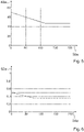
- FIG. 7 shows a diagram in which a power is plotted on an ordinate axis 56a. On an abscissa axis 58a is in 7 a number of iterations plotted. A line shown corresponds to the detected current setpoint power value 46a.
- FIG. 8 shows a diagram in which the phase shift of the current through the first induction element 12a and the current through the second induction element 14a is plotted on an ordinate axis 60a. On an abscissa axis 62a is in 8 a number of iterations plotted. A line shown corresponds to the detected current phase shift value 44a.
- FIG. 9 shows a diagram in which a voltage phase shift of the frequency units 18a, 20a is plotted on an ordinate axis 64a. On an abscissa axis 66a is in 9 a number of iterations plotted.
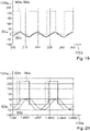
- 10 shows a diagram in which the ratio of the current through the first induction element 12a and the current through the second induction element 14a is plotted on an ordinate axis 68a. On an abscissa axis 70a is in 10 a number of iterations plotted. A line shown corresponds to the detected current current ratio value 42a.
- FIG. 11 shows a diagram in which a current intensity of the frequency units 18a, 20a and a voltage of the frequency units 18a, 20a are plotted on an ordinate axis 72a, specifically at the beginning of the regulation and for example after a maximum of 25 iterations.
- On an abscissa axis 74a is in 11 applied for a time.
- a voltage curve 80a of the first frequency unit 18a is shown in dashed lines.
- a current profile 82a of the first frequency unit 18a is shown in dashed lines.
- a voltage profile 84a of the second frequency unit 20a corresponds to the voltage profile 80a of the first frequency unit 18a.
- a current profile 86a of the second frequency unit 20a is shown as a solid line.
- FIG. 12 shows a diagram in which a current intensity of the frequency units 18a, 20a and a voltage of the frequency units 18a, 20a are plotted on an ordinate axis 76a, in particular at the end of the regulation and for example after at least 175 iterations.
- a voltage curve 80a of the first frequency unit 18a is shown in dashed lines.
- a current profile 82a of the first frequency unit 18a is shown in dashed lines.
- a voltage curve 84a of the second frequency unit 20a is solid shown.
- a current profile 86a of the second frequency unit 20a is shown as a solid line.
- the control unit 16a carries out the regulation iteratively. After a number of essentially 200 iterations, the control unit 16a in the operating state has regulated the current current ratio value 42a essentially to the preset current ratio value 30a. In the operating state, after a number of essentially 200 iterations, the control unit 16a has regulated the current phase shift value 44a essentially to the preset phase shift value 32a. After a number of essentially 200 iterations, the control unit 16a in the operating state has regulated the current setpoint power value 46a essentially to the preset setpoint power value 34a.
- a second example is shown, which is freely chosen without loss of generality.
- a value of 70 kHz is assumed as the starting value for a frequency with which the control unit 16a operates in the operating state, in particular the first induction element 12a and the second induction element 14a.
- a value of 0.5 is assumed as the starting value of the first duty cycle and the second duty cycle.
- a value of zero is assumed as the starting value of a voltage phase shift of the frequency units 18a, 20a.
- a value of 1.1 is assumed as the starting value of the ratio of the current through the first induction element 12a and the current through the second induction element 14a.
- a value of 6000 W is assumed as the preset target power value 34a.
- FIG. 13 shows a diagram in which a frequency of the first frequency unit 18a and/or the second frequency unit 20a is plotted on an ordinate axis 96a. On an abscissa axis 98a is in 13 a number of iterations plotted.
- FIG. 14 shows a diagram in which a first duty cycle of the first frequency unit 18a (dashed line) and a second duty cycle of the second frequency unit 20a (solid line) are plotted on an ordinate axis 100a. On an abscissa axis 102a is in 14 a number of iterations plotted.
- FIG. 15 shows a diagram in which a power is plotted on an ordinate axis 104a. On an abscissa axis 106a is in 15 a number of iterations plotted. A line shown corresponds to the detected current setpoint power value 46a.
- 16 shows a diagram in which the phase shift of the current through the first induction element 12a and the current through the second induction element 14a is plotted on an ordinate axis 108a. On an abscissa axis 110a is in 16 a number of iterations plotted. A line shown corresponds to the detected current phase shift value 44a.
- 17 shows a diagram in which a voltage phase shift of the frequency units 18a, 20a is plotted on an ordinate axis 112a. On an abscissa axis 114a is in 17 a number of iterations plotted.
- FIG. 18 shows a diagram in which the ratio of the current through the first induction element 12a and the current through the second induction element 14a is plotted on an ordinate axis 116a. On an abscissa axis 118a is in 18 a number of iterations plotted. A line shown corresponds to the detected current current ratio value 42a.
- 19 shows a diagram in which a current intensity of the frequency units 18a, 20a and a voltage of the frequency units 18a, 20a are plotted on an ordinate axis 120a, specifically at the beginning of the regulation and for example after a maximum of 25 iterations.
- a voltage curve 80a of the first frequency unit 18a is shown in dashed lines.
- a current profile 82a of the first frequency unit 18a is shown in dashed lines.
- a voltage profile 84a of the second frequency unit 20a corresponds to the voltage profile 80a of the first frequency unit 18a.
- a current profile 86a of the second frequency unit 20a is shown as a solid line.
- FIG. 20 shows a diagram in which a current strength of the frequency units 18a, 20a and a voltage of the frequency units 18a, 20a are plotted on an ordinate axis 124a, specifically at one end of the regulation and for example after at least 275 iterations.
- a voltage curve 80a of the first frequency unit 18a is shown in dashed lines.
- a current profile 82a of the first frequency unit 18a is shown in dashed lines.
- a voltage curve 84a of the second frequency unit 20a is shown as a solid line.
- a current profile 86a of the second frequency unit 20a is shown as a solid line.
- the control unit 16a carries out the regulation iteratively. After a number of essentially 300 iterations, the control unit 16a in the operating state has regulated the current current ratio value 42a essentially to the preset current ratio value 30a. In the operating state, after a number of essentially 300 iterations, the control unit 16a has regulated the current phase shift value 44a essentially to the preset phase shift value 32a. After a number of essentially 300 iterations, the control unit 16a in the operating state has regulated the current setpoint power value 46a essentially to the preset setpoint power value 34a.
Description
Die Erfindung betrifft eine Induktionsvorrichtung nach dem Oberbegriff des Anspruchs 1 und ein Verfahren zu einem Betrieb einer Induktionsvorrichtung nach dem Oberbegriff des Anspruchs 11The invention relates to an induction device according to the preamble of
Aus der internationalen Patentanmeldung
Die Aufgabe der Erfindung besteht insbesondere darin, eine gattungsgemäße Vorrichtung mit verbesserten Eigenschaften hinsichtlich einer Energieübertragung bereitzustellen. Die Aufgabe wird erfindungsgemäß durch die Merkmale der Ansprüche 1 und 11 gelöst, während vorteilhafte Ausgestaltungen und Weiterbildungen der Erfindung den Unteransprüchen entnommen werden können.The object of the invention consists in particular in providing a generic device with improved properties with regard to energy transmission. The object is achieved according to the invention by the features of
Die Erfindung geht aus von Induktionsvorrichtung, insbesondere Induktionsgargerätevorrichtung und vorteilhaft Induktionskochfeldvorrichtung, mit zumindest einem ersten Induktionselement, mit zumindest einem zweiten Induktionselement, welches in einem Nahbereich des ersten Induktionselements angeordnet ist und welches insbesondere in wenigstens einem Betriebszustand mit dem ersten Induktionselement koppelt, und mit zumindest einer Steuereinheit, welche die Induktionselemente in wenigstens einem Betriebszustand zeitgleich insbesondere mit einer Periodendauer betreibt.The invention is based on an induction device, in particular an induction cooking appliance device and advantageously an induction hob device, with at least one first induction element, with at least one second induction element, which is arranged in the vicinity of the first induction element and which in particular couples to the first induction element in at least one operating state, and with at least a control unit, which Induction elements operates in at least one operating state at the same time, in particular with a period.
Es wird vorgeschlagen, dass die Steuereinheit in dem Betriebszustand ein Verhältnis eines Stroms durch das erste Induktionselement und eines Stroms durch das zweite Induktionselement insbesondere zu zumindest einem Zeitpunkt der Periodendauer und vorteilhaft zu jedem Zeitpunkt der Periodendauer wenigstens im Wesentlichen auf einen voreingestellten Stromverhältniswert regelt.It is proposed that the control unit in the operating state regulates a ratio of a current through the first induction element and a current through the second induction element, in particular at least at one point in time of the period and advantageously at each point in time of the period, at least essentially to a preset current ratio value.
Durch die erfindungsgemäße Ausgestaltung kann insbesondere eine optimierte Energieübertragung erreicht werden, bei welcher insbesondere ein Einfluss einer Kopplung der Induktionselemente minimiert und/oder kalkulierbar gemacht werden kann. Insbesondere kann eine optimale Verteilung der Energie, beispielsweise im Fall einer induktiven Beheizung eine optimale Wärmeverteilung in einem Gargeschirrboden, erzielt werden. Es können insbesondere Hotspots und/oder Coldspots vermieden werden. Insbesondere kann eine hohe Flexibilität hinsichtlich einer Anwendbarkeit erzielt werden, weshalb beispielsweise im Fall einer induktiven Beheizung von Gargeschirr eine Vielzahl an verschiedenen Gargeschirren beheizt werden kann, und zwar insbesondere unabhängig von einem Material des Gargeschirrs und/oder von einer Position des Gargeschirrs und/oder von einer Größe des Gargeschirrs. Es kann insbesondere eine kontinuierliche Energieübertragung, insbesondere in Form einer Beheizung, bereitgestellt werden, wodurch insbesondere Flicker vermieden und/oder eine optimierte und/oder gleichmäßige Energieübertragung, insbesondere Beheizung, erzielt werden kann.The configuration according to the invention makes it possible in particular to achieve an optimized energy transmission, in which in particular an influence of a coupling of the induction elements can be minimized and/or made calculable. In particular, an optimal distribution of the energy, for example in the case of inductive heating an optimal distribution of heat in a cookware base, can be achieved. In particular, hot spots and/or cold spots can be avoided. In particular, a high degree of flexibility in terms of applicability can be achieved, which is why, for example, in the case of inductive heating of cookware, a large number of different cookware can be heated, in particular independently of a material of the cookware and/or of a position of the cookware and/or of a size of the cookware. In particular, a continuous transfer of energy, in particular in the form of heating, can be provided, as a result of which flicker can be avoided in particular and/or an optimized and/or uniform transfer of energy, in particular heating, can be achieved.
Unter einer "Induktionsvorrichtung", insbesondere unter einer "Induktionsgargerätevorrichtung" und vorteilhaft unter einer "Induktionskochfeldvorrichtung", soll insbesondere zumindest ein Teil, insbesondere eine Unterbaugruppe, eines Induktionsgeräts, insbesondere eines Induktionsgargeräts und vorteilhaft eines Induktionskochfelds, verstanden werden. Das die Induktionsvorrichtung aufweisende Induktionsgerät könnte beispielsweise einer Energieübertragungsgerät sein, welches insbesondere zu einer Energieübertragung an zumindest eine weitere Einheit, insbesondere zumindest eine Sekundärspule eines Verbrauchers, vorgesehen sein könnte. Vorteilhaft ist das die Induktionsvorrichtung aufweisende Induktionsgerät ein Induktionsgargerät. Das die Induktionsvorrichtung aufweisende Induktionsgerät und insbesondere das Induktionsgargerät könnte beispielsweise ein Induktionsbackofen sein. Vorzugsweise ist das die Induktionsvorrichtung aufweisende Induktionsgerät und insbesondere das Induktionsgargerät ein Induktionskochfeld.An “induction device”, in particular an “induction cooking appliance device” and advantageously an “induction hob appliance”, should be understood to mean in particular at least a part, in particular a subassembly, of an induction appliance, in particular an induction cooking appliance and advantageously an induction hob. The induction device having the induction device could be an energy transmission device, for example, which could be provided in particular for transmitting energy to at least one further unit, in particular at least one secondary coil of a consumer. The induction appliance having the induction device is advantageously an induction cooking appliance. The induction device having the induction device and in particular the induction cooking appliance could be an induction oven, for example. The induction appliance having the induction device and in particular the induction cooking appliance is preferably an induction hob.
Unter einem "Induktionselement" soll insbesondere ein Element verstanden werden, welches in wenigstens einem Betriebszustand Energie insbesondere zum Zweck einer induktiven Energieübertragung bereitstellt. Das Induktionselement könnte insbesondere eine Primärspule ausbilden, welche insbesondere zu einer induktiven Energieübertragung an zumindest eine Sekundärspule vorgesehen sein könnte. Die Sekundärspule könnte beispielsweise Teil eines Energieübertragungssystems sein, welches insbesondere die Induktionsvorrichtung aufweisen könnte. Insbesondere könnte die Sekundärspule in zumindest einem Verbraucher wenigstens zu einem Großteil integriert sein. Der Verbraucher könnte beispielsweise eine Handwerkzeugmaschine und/oder ein Auto und/oder ein Laptop und/oder ein Tablet und/oder ein Mobiltelefon sein. Alternativ oder zusätzlich könnte das Induktionselement insbesondere als ein Induktionsheizelement ausgebildet sein und insbesondere zu einer Energieübertragung an zumindest ein Gargeschirr insbesondere zum Zweck einer Erhitzung des Gargeschirrs vorgesehen sein. Das Induktionselement könnte in wenigstens einem Betriebszustand insbesondere ein Wechselfeld, insbesondere ein elektromagnetisches Wechselfeld, mit einer Frequenz von mindestens 1 Hz, insbesondere von mindestens 2 Hz, vorteilhaft von mindestens 5 Hz und vorzugsweise von mindestens 10 Hz bereitstellen. Insbesondere könnte das Induktionselement in wenigstens einem Betriebszustand insbesondere ein Wechselfeld, insbesondere ein elektromagnetisches Wechselfeld, mit einer Frequenz von maximal 150 kHz, insbesondere von maximal 120 kHz, vorteilhaft von maximal 100 kHz und vorzugsweise von maximal 80 kHz bereitstellen. Ein insbesondere als Induktionsheizelement ausgebildetes Induktionselement könnte in wenigstens einem Betriebszustand insbesondere ein hochfrequentes Wechselfeld, insbesondere ein hochfrequentes elektromagnetisches Wechselfeld, mit einer Frequenz von mindestens 15 kHz und insbesondere von maximal 100 kHz bereitstellen.An "induction element" is to be understood in particular as an element which, in at least one operating state, provides energy, in particular for the purpose of inductive energy transmission. In particular, the induction element could form a primary coil, which could be provided in particular for inductive energy transmission to at least one secondary coil. The secondary coil could, for example, be part of an energy transmission system, which in particular could have the induction device. In particular, the secondary coil could be integrated at least to a large extent in at least one consumer. The consumer could be, for example, a handheld power tool and/or a car and/or a laptop and/or a tablet and/or a mobile phone. Alternatively or additionally, the induction element could be designed in particular as an induction heating element and be provided in particular for energy transfer to at least one cooking utensil, in particular for the purpose of heating the cooking utensil. In at least one operating state, the induction element could provide in particular an alternating field, in particular an alternating electromagnetic field, with a frequency of at least 1 Hz, in particular at least 2 Hz, advantageously at least 5 Hz and preferably at least 10 Hz. In particular, in at least one operating state, the induction element could provide an alternating field, in particular an alternating electromagnetic field, with a maximum frequency of 150 kHz, in particular a maximum of 120 kHz, advantageously a maximum of 100 kHz and preferably a maximum of 80 kHz. An induction element designed in particular as an induction heating element could, in at least one operating state, provide in particular a high-frequency alternating field, in particular a high-frequency electromagnetic alternating field, with a frequency of at least 15 kHz and in particular a maximum of 100 kHz.
Die Induktionsvorrichtung könnte beispielsweise ausschließlich das erste Induktionselement und das zweite Induktionselement aufweisen. Vorteilhaft weist die Induktionsvorrichtung, insbesondere insgesamt, zumindest drei, vorteilhaft zumindest vier, besonders vorteilhaft zumindest fünf und vorzugsweise mehrere Induktionselemente auf. Insbesondere könnte ein insbesondere beliebiges der Induktionselemente in einem Nahbereich zu zumindest einem weiteren der Induktionselemente angeordnet sein. Zumindest ein Teil der Induktionselemente könnte beispielsweise in einer Reihe und/oder in Form einer Matrix angeordnet sein. Unter "wenigstens zu einem Großteil" soll insbesondere zu einem Anteil, insbesondere einem Massenanteil und/oder Volumenanteil, von mindestens 70 %, insbesondere von mindestens 80 %, vorteilhaft von mindestens 90 % und vorzugsweise von mindestens 95 % verstanden werden.The induction device could, for example, only have the first induction element and the second induction element. The induction device advantageously has at least three, advantageously at least four, particularly advantageously at least five and preferably a plurality of induction elements, in particular in total. In particular, any one of the induction elements could be arranged in close proximity to at least one other of the induction elements. At least some of the induction elements could be arranged in a row and/or in the form of a matrix, for example. “At least for the most part” is to be understood as meaning in particular a proportion, in particular a mass proportion and/or volume proportion, of at least 70%, in particular at least 80%, advantageously at least 90% and preferably at least 95%.
Unter der Wendung, dass ein erstes Objekt in einem "Nahbereich" eines zweiten Objekts angeordnet ist, soll insbesondere verstanden werden, dass bei einer senkrechten Betrachtung auf eine Haupterstreckungsebene des ersten Objekts und/oder des zweiten Objekts ein Abstand einer seitlichen Begrenzung des ersten Objekts zu einer nächstgelegenen seitlichen Begrenzung des zweiten Objekts maximal 60 %, insbesondere maximal 50 %, vorteilhaft maximal 40 %, besonders vorteilhaft maximal 30%, vorzugsweise maximal 20% und besonders bevorzugt maximal 10% einer Längserstreckung des ersten Objekts und/oder des zweiten Objekts beträgt. Alternativ oder zusätzlich soll unter der Wendung, dass ein erstes Objekt in einem "Nahbereich" eines zweiten Objekts angeordnet ist, insbesondere verstanden werden, dass bei einer senkrechten Betrachtung auf eine Haupterstreckungsebene des ersten Objekts und/oder des zweiten Objekts ein Abstand eines Mittelpunkts und/oder Schwerpunkts des ersten Objekts zu einem nächstgelegenen Mittelpunkt und/oder Schwerpunkt des zweiten Objekts maximal 150%, insbesondere maximal 120%, vorteilhaft maximal 100%, besonders vorteilhaft maximal 80 %, vorzugsweise maximal 60 % und besonders bevorzugt maximal 50 % einer Längserstreckung des ersten Objekts und/oder des zweiten Objekts beträgt.The expression that a first object is arranged in a "close range" of a second object is to be understood in particular as meaning that when viewed perpendicularly to a main extension plane of the first object and/or the second object, there is a distance from a lateral boundary of the first object a closest lateral boundary of the second object is at most 60%, in particular at most 50%, advantageously at most 40%, particularly advantageously at most 30%, preferably at most 20% and particularly preferably at most 10% of a longitudinal extent of the first object and/or the second object. Alternatively or additionally, the phrase that a first object is arranged in a “close range” of a second object should be understood in particular to mean that when viewed perpendicularly onto a main extension plane of the first object and/or the second object, a distance between a center point and/or or focus of the first object to a nearest center and/or focus of the second object is a maximum of 150%, in particular a maximum of 120%, advantageously a maximum of 100%, particularly advantageously a maximum of 80%, preferably a maximum of 60% and particularly preferably a maximum of 50% of a longitudinal extension of the first Object and / or the second object is.
Unter einer "Haupterstreckungsebene" eines Objekts soll insbesondere eine Ebene verstanden werden, welche parallel zu einer größten Seitenfläche eines kleinsten gedachten geometrischen Quaders ist, welcher das Objekt gerade noch vollständig umschließt, und insbesondere durch den Mittelpunkt des Quaders verläuft. Unter einer "Längserstreckung" eines Objekts soll insbesondere Erstreckung des Objekts entlang einer Längserstreckungsrichtung des Objekts verstanden werden. Unter einer "Längserstreckungsrichtung" eines Objekts soll insbesondere eine Richtung verstanden werden, welche parallel zu einer längsten Seite eines kleinsten gedachten geometrischen Quaders ausgerichtet ist, welcher das Objekt gerade noch vollständig umschließt. Unter einer "Erstreckung" eines Objekts soll insbesondere ein maximaler Abstand zweier Punkte einer senkrechten Projektion des Objekts auf eine Ebene verstanden werden.A "main extension plane" of an object is to be understood in particular as a plane which is parallel to a largest side face of the smallest imaginary geometric cuboid which just completely encloses the object and in particular runs through the center point of the cuboid. A “longitudinal extent” of an object is to be understood in particular as an extent of the object along a direction of longitudinal extent of the object. A "longitudinal direction" of an object is to be understood in particular as a direction which is parallel to a longest side of a smallest imaginary geometric cuboid is aligned, which just completely encloses the object. An "extension" of an object is to be understood in particular as a maximum distance between two points of a perpendicular projection of the object onto a plane.
Unter einer "Steuereinheit" soll insbesondere eine elektronische Einheit verstanden werden, die vorzugsweise in einer Steuer- und/oder Regeleinheit eines Induktionsgeräts zumindest teilweise integriert ist und die vorzugsweise dazu vorgesehen ist, zumindest die Induktionselemente und/oder zumindest eine Frequenzeinheit zu steuern und/oder zu regeln. Vorzugsweise umfasst die Steuereinheit eine Recheneinheit und insbesondere zusätzlich zur Recheneinheit eine Speichereinheit mit einem darin gespeicherten Steuer- und/oder Regelprogramm, das dazu vorgesehen ist, von der Recheneinheit ausgeführt zu werden.A "control unit" is to be understood in particular as an electronic unit which is preferably at least partially integrated in a control and/or regulation unit of an induction device and which is preferably provided to control at least the induction elements and/or at least one frequency unit and/or to settle. Preferably, the control unit comprises an arithmetic unit and, in particular, in addition to the arithmetic unit, a memory unit with a control and/or regulation program stored therein, which is intended to be executed by the arithmetic unit.
In dem Betriebszustand vermeidet die Steuereinheit insbesondere ein Betreiben der Induktionselemente in einem Multiplex-Verfahren und/oder ein abwechselndes Betreiben der Induktionselemente. Die Steuereinheit vermeidet in dem Betriebszustand insbesondere ein Abschalten zumindest eines der Induktionselemente insbesondere in der Periodendauer. Insbesondere aktiviert und/oder betreibt die Steuereinheit die Induktionselemente durchgehend und/oder pausenlos und/oder ununterbrochen. Unter einem "Betriebszustand" soll insbesondere ein Zustand verstanden werden, in welchem die Steuereinheit die Induktionselemente mit Energie versorgt und insbesondere zu einer Versorgung der Induktionselemente zumindest eine Frequenzeinheit, vorteilhaft zumindest eine Frequenzeinheit pro Induktionselement, ansteuert. Die Induktionsvorrichtung weist insbesondere zumindest eine Frequenzeinheit, insbesondere pro Induktionselement, auf, welche zu einer Energieversorgung von zumindest einem der Induktionselemente, insbesondere von genau einem der Induktionselemente, vorgesehen ist.In the operating state, the control unit avoids in particular operating the induction elements in a multiplex process and/or operating the induction elements alternately. In the operating state, the control unit in particular avoids switching off at least one of the induction elements, in particular in the period duration. In particular, the control unit activates and/or operates the induction elements continuously and/or without a break and/or uninterrupted. An “operating state” is to be understood in particular as a state in which the control unit supplies the induction elements with energy and in particular controls at least one frequency unit, advantageously at least one frequency unit per induction element, to supply the induction elements. The induction device has in particular at least one frequency unit, in particular per induction element, which is provided for supplying energy to at least one of the induction elements, in particular to exactly one of the induction elements.
Unter einer "Frequenzeinheit" soll insbesondere eine Einheit verstanden werden, welche in wenigstens einem Betriebszustand insbesondere zum Zweck einer Energieversorgung zumindest eines der Induktionselemente, vorteilhaft genau eines der Induktionselemente, zumindest einen Wechselstrom bereitstellt. Vorteilhaft ist die Frequenzeinheit als Heizfrequenzeinheit ausgebildet und stellt insbesondere in dem Betriebszustand einen hochfrequenten Wechselstrom zu einer Energieversorgung zumindest eines der Induktionselemente bereit. Insbesondere könnte die Frequenzeinheit zumindest ein Schaltelement, insbesondere zumindest ein Halbleitungsschaltelement, und/oder vorteilhaft zumindest einen Wechselrichter und/oder Inverter aufweisen.A "frequency unit" is to be understood in particular as a unit which provides at least one alternating current in at least one operating state, in particular for the purpose of supplying energy to at least one of the induction elements, advantageously precisely one of the induction elements. The frequency unit is advantageously designed as a heating frequency unit and, in particular in the operating state, provides a high-frequency alternating current to a power supply for at least one of the Induction elements ready. In particular, the frequency unit could have at least one switching element, in particular at least one semiconductor switching element, and/or advantageously at least one inverter and/or inverter.
Unter einem "voreingestellten" Wert soll insbesondere ein Wert verstanden werden, welcher insbesondere zeitlich gesehen vor einem Beginn eines Betriebs der Induktionselemente festgelegt und/oder definiert ist. Beispielsweise könnte die Steuereinheit den voreingestellten Wert insbesondere vor einem Beginn eines Betriebs der Induktionselemente festlegen und/oder ermitteln. Die Steuereinheit könnte den voreingestellten Wert beispielsweise in Abhängigkeit von zumindest einem Geometriefaktor und/oder in Abhängigkeit von zumindest einem Strukturfaktor festlegen und/oder ermitteln. Alternativ oder zusätzlich könnte die Steuereinheit insbesondere zumindest eine Speichereinheit aufweisen, in welcher insbesondere der voreingestellte Wert, insbesondere von Werk ab und/oder dauerhaft und/oder unveränderbar, gespeichert sein könnte.A “preset” value should be understood to mean, in particular, a value which, viewed in terms of time, is specified and/or defined before the start of operation of the induction elements. For example, the control unit could define and/or determine the preset value, in particular before the induction elements start operating. The control unit could define and/or determine the preset value, for example, as a function of at least one geometry factor and/or as a function of at least one structural factor. Alternatively or additionally, the control unit could in particular have at least one memory unit in which in particular the preset value could be stored, in particular ex works and/or permanently and/or unchangeably.
Unter der Wendung, dass die Steuereinheit ein Verhältnis und/oder eine Phasenverschiebung und/oder eine Gesamtleistung "wenigstens im Wesentlichen" auf einen voreingestellten Wert regelt, soll insbesondere verstanden werden, dass die Steuereinheit das Verhältnis und/oder die Phasenverschiebung und/oder die Gesamtleistung auf einen Wert regelt, welcher mindestens 50 %, insbesondere mindestens 60 %, vorteilhaft mindestens 70 %, besonders vorteilhaft mindestens 80 %, vorzugsweise mindestens 90 % und besonders bevorzugt mindestens 95 % des voreingestellten Werts beträgt und/oder welcher maximal 150 %, insbesondere maximal 140%, vorteilhaft maximal 130%, besonders vorteilhaft maximal 120%, vorzugsweise maximal 110% und besonders bevorzugt maximal 105% des voreingestellten Werts beträgt.The expression that the control unit regulates a ratio and/or a phase shift and/or a total power "at least substantially" to a preset value is to be understood in particular that the control unit adjusts the ratio and/or the phase shift and/or the total power regulates to a value which is at least 50%, in particular at least 60%, advantageously at least 70%, particularly advantageously at least 80%, preferably at least 90% and particularly preferably at least 95% of the preset value and/or which is at most 150%, in particular at most 140%, advantageously at most 130%, particularly advantageously at most 120%, preferably at most 110% and particularly preferably at most 105% of the preset value.
Unter der Wendung, dass die Steuereinheit ein Verhältnis und/oder eine Phasenverschiebung und/oder eine Gesamtleistung wenigstens im Wesentlichen auf einen voreingestellten Wert "regelt", soll insbesondere verstanden werden, dass die Steuereinheit das Verhältnis und/oder die Phasenverschiebung und/oder die Gesamtleistung durch Anpassung und/oder durch Änderung zumindest einer Betriebskenngröße, insbesondere zumindest einer Betriebskenngröße zumindest einer Frequenzeinheit, vorzugsweise iterativ, wenigstens im Wesentlichen auf den voreingestellten Wert einstellt und/oder wenigstens im Wesentlichen an den voreingestellten Wert anpasst.The phrase that the control unit “regulates” a ratio and/or a phase shift and/or a total power at least essentially to a preset value is to be understood in particular to mean that the control unit controls the ratio and/or the phase shift and/or the total power by adapting and/or changing at least one operating parameter, in particular at least one operating parameter frequency unit, preferably iteratively, at least substantially to the preset value and/or at least substantially adapts to the preset value.
Die Induktionsvorrichtung weist insbesondere zumindest eine Detektionseinheit auf, welche insbesondere zu einer Detektion zumindest einer elektrischen Kenngröße vorgesehen ist. Die elektrische Kenngröße könnte beispielsweise ein aktueller Stromverhältniswert und/oder ein aktueller Phasenverschiebungswert und/oder ein aktueller Sollleistungswert sein.In particular, the induction device has at least one detection unit, which is provided in particular for detecting at least one electrical parameter. The electrical parameter could be, for example, a current current ratio value and/or a current phase shift value and/or a current setpoint power value.
Unter "vorgesehen" soll insbesondere speziell programmiert, ausgelegt und/oder ausgestattet verstanden werden. Darunter, dass ein Objekt zu einer bestimmten Funktion vorgesehen ist, soll insbesondere verstanden werden, dass das Objekt diese bestimmte Funktion in zumindest einem Anwendungs- und/oder Betriebszustand erfüllt und/oder ausführt.“Provided” should be understood to mean, in particular, specially programmed, designed and/or equipped. The fact that an object is provided for a specific function is to be understood in particular to mean that the object fulfills and/or executes this specific function in at least one application and/or operating state.
Ferner wird vorgeschlagen, dass der voreingestellte Stromverhältniswert in dem Betriebszustand von zumindest einem Strukturfaktor abhängig ist. Unter einem "Strukturfaktor" soll insbesondere ein Faktor verstanden werden, welcher eine Situation einer Energieübertragung kennzeichnet. Beispielsweise könnte der Strukturfaktor eine Anordnung der Induktionselemente relativ zueinander und/oder eine Anordnung zumindest eines der Induktionselemente relativ zu zumindest einem Verbraucher und/oder eine Anordnung zumindest eines der Induktionselemente relativ zu zumindest einem Abschirmelement und/oder zumindest eine Eigenschaft von zumindest einem Verbraucher und/oder zumindest eine Eigenschaft zumindest eines der Induktionselemente aufweisen. Die Eigenschaft des Verbrauchers könnte beispielsweise ein Material des Verbrauchers und/oder eine Geometrie des Verbrauchers und/oder eine Größe des Verbrauchers sein. Die Eigenschaft zumindest eines der Induktionselemente könnte beispielsweise ein Material des Induktionselements und/oder eine Geometrie des Induktionselements und/oder eine Größe des Induktionselements und/oder ein dem Induktionselement zugeordnetes Ferritelement und/oder eine Windungszahl des Induktionselements sein. Dadurch kann insbesondere eine optimierte Energieübertragung erzielt werden, da insbesondere der voreingestellte Stromverhältniswert in Abhängigkeit des Strukturfaktors für eine insbesondere beliebige Situation insbesondere flexibel gewählt und/oder festgelegt werden kann.Furthermore, it is proposed that the preset current ratio value in the operating state is dependent on at least one structure factor. A "structure factor" is to be understood in particular as a factor which characterizes an energy transmission situation. For example, the structure factor could be an arrangement of the induction elements relative to one another and/or an arrangement of at least one of the induction elements relative to at least one consumer and/or an arrangement of at least one of the induction elements relative to at least one shielding element and/or at least one property of at least one consumer and/or or have at least one property of at least one of the induction elements. The attribute of the consumer could be, for example, a material of the consumer and/or a geometry of the consumer and/or a size of the consumer. The property of at least one of the induction elements could be, for example, a material of the induction element and/or a geometry of the induction element and/or a size of the induction element and/or a ferrite element assigned to the induction element and/or a number of turns of the induction element. In this way, in particular, an optimized energy transfer can be achieved, since in particular the preset current ratio value depends of the structure factor can be selected and/or specified in a particularly flexible manner for any particular situation.
Zudem wird vorgeschlagen, dass der voreingestellte Stromverhältniswert durch ein Verhältnis einer Windungszahl des zweiten Induktionselements und einer Windungszahl des ersten Induktionselements definiert ist. Insbesondere weist der Strukturfaktor ein Verhältnis einer Windungszahl des zweiten Induktionselements und einer Windungszahl des ersten Induktionselements auf und könnte beispielsweise als ein Verhältnis einer Windungszahl des zweiten Induktionselements und einer Windungszahl des ersten Induktionselements ausgebildet sein. Dadurch kann insbesondere eine Geometrie der Induktionselemente bei einer Energieübertragung und/oder bei einer Festlegung des Stromverhältniswerts berücksichtigt werden, wodurch insbesondere eine hohe Flexibilität ermöglicht und/oder Energie in optimierter Art und Weise übertragen werden kann, und zwar insbesondere unter Vermeidung von Hotspots und/oder Coldspots.In addition, it is proposed that the preset current ratio value is defined by a ratio of a number of turns of the second induction element and a number of turns of the first induction element. In particular, the structure factor has a ratio of a number of turns of the second induction element and a number of turns of the first induction element and could be formed, for example, as a ratio of a number of turns of the second induction element and a number of turns of the first induction element. In this way, in particular, a geometry of the induction elements can be taken into account during energy transmission and/or when determining the current ratio value, which in particular enables a high degree of flexibility and/or energy can be transmitted in an optimized manner, in particular while avoiding hotspots and/or cold spots.
Beispielsweise könnte der voreingestellte Stromverhältniswert mindestens 0,6, insbesondere mindestens 0,65, vorteilhaft mindestens 0,7, besonders vorteilhaft mindestens 0,75 und vorzugsweise mindestens 0,8 betragen. Alternativ oder zusätzlich könnte der voreingestellte Stromverhältniswert maximal 1,5, insbesondere maximal 1,4, vorteilhaft maximal 1,3, besonders vorteilhaft maximal 1,25 und vorzugsweise maximal 1,2 betragen. Vorzugsweise beträgt der voreingestellte Stromverhältniswert wenigstens im Wesentlichen eins, und zwar insbesondere im Fall, dass die Induktionselemente wenigstens im Wesentlichen identisch ausgebildet sind und insbesondere bei einer senkrechten Betrachtung auf eine Haupterstreckungsebene des ersten Induktionselements und/oder des zweiten Induktionselements wenigstens abschnittsweise überlappend angeordnet sind. Unter "wenigstens im Wesentlichen" soll in diesem Zusammenhang insbesondere verstanden werden, dass eine Abweichung von einem vorgegebenen Wert insbesondere weniger als 25 %, vorzugsweise weniger als 10 % und besonders bevorzugt weniger als 5 % des vorgegebenen Werts abweicht. Insbesondere beträgt der voreingestellte Stromverhältniswert mindestens 0,9, insbesondere mindestens 0,92, vorteilhaft mindestens 0,94, besonders vorteilhaft mindestens 0,95, vorzugsweise mindestens 0,97 und besonders bevorzugt mindestens 0,99. Insbesondere beträgt der voreingestellte Stromverhältniswert maximal 1,1, insbesondere maximal 1,08, vorteilhaft maximal 1,06, besonders vorteilhaft maximal 1,05, vorzugsweise maximal 1,03 und besonders bevorzugt maximal 1,01. Dadurch kann insbesondere eine gleichmäßige und/oder optimierte Energieübertragung gewährleistet werden.For example, the preset current ratio value could be at least 0.6, in particular at least 0.65, advantageously at least 0.7, particularly advantageously at least 0.75 and preferably at least 0.8. Alternatively or additionally, the preset current ratio value could be a maximum of 1.5, in particular a maximum of 1.4, advantageously a maximum of 1.3, particularly advantageously a maximum of 1.25 and preferably a maximum of 1.2. The preset current ratio value is preferably at least essentially one, in particular if the induction elements are of at least essentially identical design and are arranged in an overlapping manner at least in sections when viewed perpendicularly to a main extension plane of the first induction element and/or the second induction element. In this context, “at least essentially” is to be understood in particular as meaning that a deviation from a specified value deviates in particular by less than 25%, preferably less than 10% and particularly preferably less than 5% of the specified value. In particular, the preset current ratio value is at least 0.9, in particular at least 0.92, advantageously at least 0.94, particularly advantageously at least 0.95, preferably at least 0.97 and particularly preferably at least 0.99. In particular, the preset current ratio value is at most 1.1, in particular at most 1.08, advantageously at most 1.06, particularly advantageously at most 1.05, preferably at most 1.03 and particularly preferably at most 1.01. In this way, in particular, a uniform and/or optimized transmission of energy can be ensured.
Ferner wird vorgeschlagen, dass die Steuereinheit in dem Betriebszustand eine Phasenverschiebung des Stroms durch das erste Induktionselement und des Stroms durch das zweite Induktionselement insbesondere zu zumindest einem Zeitpunkt der Periodendauer und vorteilhaft zu jedem Zeitpunkt der Periodendauer wenigstens im Wesentlichen auf einen voreingestellten Phasenverschiebungswert regelt. Dadurch kann insbesondere ein Auftreten von Hotspots und/oder Coldspots vermieden werden. Insbesondere kann, insbesondere im Fall einer Beheizung eines Gargeschirrs, eine optimierte und/oder gleichmäßige Wärmeverteilung in einem Gargeschirrboden erzielt werden.It is also proposed that the control unit in the operating state regulates a phase shift of the current through the first induction element and the current through the second induction element, in particular at least at one point in time of the period and advantageously at every point in time of the period, at least essentially to a preset phase shift value. In this way, in particular, the occurrence of hotspots and/or cold spots can be avoided. In particular, an optimized and/or uniform distribution of heat in a cooking utensil base can be achieved, particularly in the case of heating of a cooking utensil.
Der voreingestellte Phasenverschiebungswert könnte beispielsweise von zumindest einem Geometriefaktor und/oder von zumindest einem Strukturfaktor abhängig sein. Vorzugsweise ist der voreingestellte Phasenverschiebungswert von einer Anordnung des ersten Induktionselements relativ zu dem zweiten Induktionselement abhängig. Insbesondere unterscheidet sich der Phasenverschiebungswert im Fall von zwei Induktionselementen, welche bei einer senkrechten Betrachtung auf eine Haupterstreckungsebene des ersten Induktionselements und/oder des zweiten Induktionselements wenigstens abschnittsweise überlappend angeordnet sind, von einem Phasenverschiebungswert im Fall von zwei Induktionselementen, welche bei einer senkrechten Betrachtung auf eine Haupterstreckungsebene des ersten Induktionselements und/oder des zweiten Induktionselements überlappungsfrei und insbesondere benachbart zueinander angeordnet sind. Vorzugsweise beträgt der voreingestellte Phasenverschiebungswert wenigstens im Wesentlichen 60°, und zwar insbesondere im Fall, dass die Induktionselemente wenigstens im Wesentlichen identisch ausgebildet sind und insbesondere bei einer senkrechten Betrachtung auf eine Haupterstreckungsebene des ersten Induktionselements und/oder des zweiten Induktionselements wenigstens abschnittsweise überlappend angeordnet sind. Insbesondere beträgt der voreingestellte Phasenverschiebungswert mindestens 30°, insbesondere mindestens 35°, vorteilhaft mindestens 40°, besonders vorteilhaft mindestens 45°, vorzugsweise mindestens 50° und besonders bevorzugt mindestens 55°. Insbesondere beträgt der voreingestellte Phasenverschiebungswert maximal 90°, insbesondere maximal 85°, vorteilhaft maximal 80°, besonders vorteilhaft maximal 75°, vorzugsweise maximal 70° und besonders bevorzugt maximal 65°. Insbesondere im Fall, dass die Induktionselemente wenigstens im Wesentlichen identisch ausgebildet sind und insbesondere bei einer senkrechten Betrachtung auf eine Haupterstreckungsebene des ersten Induktionselements und/oder des zweiten Induktionselements überlappungsfrei und insbesondere benachbart zueinander angeordnet sind, beträgt der Phasenverschiebungswert insbesondere wenigstens im Wesentlichen 0° und/oder wenigstens im Wesentlichen 180°. Dadurch kann insbesondere für jede beliebige Anordnung des ersten Induktionselements relativ zu dem zweiten Induktionselement eine Energieübertragung optimiert werden, wodurch insbesondere ein hoher Bedienkomfort und/oder eine verlustarme Energieübertragung gewährleistet werden kann.The preset phase shift value could be dependent on at least one geometry factor and/or at least one structure factor, for example. Preferably, the preset phase shift value is dependent on a placement of the first inductor relative to the second inductor. In particular, the phase shift value in the case of two induction elements which, when viewed perpendicularly to a main extension plane of the first induction element and/or the second induction element, are arranged so that they overlap at least in sections differs from a phase shift value in the case of two induction elements which, when viewed perpendicularly, to one Main extension plane of the first induction element and / or the second induction element are arranged without overlap and in particular adjacent to each other. The preset phase shift value is preferably at least essentially 60°, in particular if the induction elements are of at least essentially identical design and are arranged in an overlapping manner at least in sections when viewed perpendicularly to a main extension plane of the first induction element and/or the second induction element. In particular, the preset phase shift value is at least 30°, in particular at least 35°, advantageously at least 40°, particularly advantageously at least 45°, preferably at least 50° and particularly preferably at least 55°. In particular, the preset phase shift value is a maximum of 90°, in particular at most 85°, advantageously at most 80°, particularly advantageously at most 75°, preferably at most 70° and particularly preferably at most 65°. In particular, if the induction elements are configured at least essentially identically and are arranged without overlapping and in particular adjacent to one another when viewed perpendicularly to a main extension plane of the first induction element and/or the second induction element, the phase shift value is in particular at least essentially 0° and/or or at least substantially 180°. As a result, energy transmission can be optimized in particular for any arrangement of the first induction element relative to the second induction element, as a result of which a high level of operating convenience and/or low-loss energy transmission can be ensured.
Weiterhin wird vorgeschlagen, dass die Induktionsvorrichtung zumindest eine erste Frequenzeinheit, welche zu einer Energieversorgung des ersten Induktionselements vorgesehen ist, und zumindest eine zweite Frequenzeinheit aufweist, welche zu einer Energieversorgung des zweiten Induktionselements vorgesehen ist. Insbesondere versorgt die erste Frequenzeinheit in wenigstens einem insbesondere beliebigen Betriebszustand das erste Induktionselement mit Energie. Insbesondere im Fall einer Aktivierung des ersten Induktionselements, empfängt das erste Induktionselement insbesondere ausschließlich von der ersten Frequenzeinheit Energie. Insbesondere versorgt die zweite Frequenzeinheit in wenigstens einem insbesondere beliebigen Betriebszustand das zweite Induktionselement mit Energie. Insbesondere im Fall einer Aktivierung des zweiten Induktionselements, empfängt das zweite Induktionselement insbesondere ausschließlich von der zweiten Frequenzeinheit Energie. Beispielsweise könnten das erste Induktionselement und das zweite Induktionselement in einer Vollbrückenschaltung angeordnet sein. Vorzugsweise sind das erste Induktionselement und das zweite Induktionselement in einer Halbbrückenschaltung angeordnet. Dadurch können die Induktionselemente insbesondere besonders effektiv und/oder effizient mit Energie versorgt werden, wodurch eine Energieübertragung insbesondere optimiert und/oder genau dosiert werden kann.It is also proposed that the induction device has at least one first frequency unit, which is provided for supplying energy to the first induction element, and at least one second frequency unit, which is provided for supplying energy to the second induction element. In particular, the first frequency unit supplies the first induction element with energy in at least one in particular any operating state. In particular when the first induction element is activated, the first induction element receives energy exclusively from the first frequency unit. In particular, the second frequency unit supplies the second induction element with energy in at least one in particular any operating state. In particular, when the second induction element is activated, the second induction element receives energy exclusively from the second frequency unit. For example, the first induction element and the second induction element could be arranged in a full bridge circuit. The first induction element and the second induction element are preferably arranged in a half-bridge circuit. As a result, the induction elements can be supplied with energy in a particularly effective and/or efficient manner, as a result of which energy transmission can be optimized and/or precisely metered in particular.
Ferner wird vorgeschlagen, dass die Steuereinheit in dem Betriebszustand zu der Regelung, insbesondere des Verhältnisses auf den Stromverhältniswert und/oder der Phasenverschiebung auf den Phasenverschiebungswert, zumindest eine Betriebskenngröße zumindest einer der Frequenzeinheiten anpasst und insbesondere bei Bedarf ändert. Unter einer "Betriebskenngröße" einer Frequenzeinheit soll insbesondere eine Kenngröße verstanden werden, welche einen Betrieb der Frequenzeinheit kennzeichnet. Die Betriebskenngröße könnte beispielsweise eine Frequenz der Frequenzeinheit und/oder ein Tastgrad der Frequenzeinheit aufweisen. Alternativ oder zusätzlich könnte die Betriebskenngröße eine Spannungsphasenverschiebung der Frequenzeinheiten aufweisen. Dadurch kann insbesondere auf einfache und/oder unkomplizierte Art und Weise eine genaue und/oder präzise Regelung ermöglicht werden.Furthermore, it is proposed that the control unit in the operating state for the regulation, in particular of the ratio to the current ratio value and/or the phase shift to the phase shift value, at least one Operating parameter at least one of the frequency units adapts and in particular changes if necessary. An "operating parameter" of a frequency unit is to be understood in particular as a parameter which characterizes operation of the frequency unit. The operating parameter could have a frequency of the frequency unit and/or a duty cycle of the frequency unit, for example. Alternatively or additionally, the operating parameter could have a voltage phase shift of the frequency units. As a result, an exact and/or precise regulation can be made possible in particular in a simple and/or uncomplicated manner.
In wenigstens einem Betriebszustand könnte die Steuereinheit das erste Induktionselement und das zweite Induktionselement insbesondere mit voneinander verschiedenen Frequenzen betreiben, welche sich beispielsweise um mindestens 15 kHz, insbesondere um mindestens 16 kHz, vorteilhaft um mindestens 17 kHz, besonders vorteilhaft um mindestens 18 kHz, vorzugsweise um mindestens 19 kHz und besonders bevorzugt um mindestens 20 kHz unterscheiden könnten. Vorzugsweise betreibt die Steuereinheit in dem Betriebszustand das erste Induktionselement und das zweite Induktionselement mit wenigstens im Wesentlichen der gleichen Frequenz. Dadurch kann insbesondere ein Auftreten von Intermodulationsbrummen vermieden werden, wodurch insbesondere ein hoher Bedienkomfort erzielt werden kann.In at least one operating state, the control unit could operate the first induction element and the second induction element, in particular, with different frequencies, which differ, for example, by at least 15 kHz, in particular by at least 16 kHz, advantageously by at least 17 kHz, particularly advantageously by at least 18 kHz, preferably by at least 19 kHz and more preferably by at least 20 kHz. In the operating state, the control unit preferably operates the first induction element and the second induction element with at least essentially the same frequency. In this way, in particular, the occurrence of intermodulation hum can be avoided, as a result of which a high level of operating convenience can be achieved in particular.
Vorzugsweise wird vorgeschlagen, dass die Steuereinheit in dem Betriebszustand eine Gesamtleistung der Frequenzeinheiten wenigstens im Wesentlichen auf einen voreingestellten Sollleistungswert regelt. Der Sollleistungswert könnte beispielsweise durch zumindest eine Bedienereingabe mittels zumindest einer Bedienerschnittstelle, insbesondere der Induktionsvorrichtung, vorgegeben sein. Alternativ oder zusätzlich könnte der Sollleistungswert durch zumindest ein automatisches Energieübertragungsprogramm, insbesondere durch zumindest ein automatisches Garprogramm, welches insbesondere in einer Speichereinheit der Steuereinheit gespeichert sein könnte, vorgegeben sein. Dadurch kann insbesondere ein hoher Bedienkomfort erzielt werden, und zwar insbesondere aufgrund einer optimal und/oder präzise einstellbaren Energieübertragung, insbesondere Beheizung.It is preferably proposed that the control unit regulates a total power of the frequency units at least essentially to a preset setpoint power value in the operating state. The setpoint power value could be specified, for example, by at least one operator input using at least one operator interface, in particular the induction device. Alternatively or additionally, the setpoint power value could be specified by at least one automatic energy transfer program, in particular by at least one automatic cooking program, which could be stored in particular in a memory unit of the control unit. In this way, in particular, a high level of operating comfort can be achieved, in particular due to an energy transfer that can be optimally and/or precisely adjusted, in particular heating.
Das erste Induktionselement und das zweite Induktionselement könnten beispielsweise direkt zueinander benachbart angeordnet und insbesondere Teil einer Matrixanordnung von Induktionselementen sein. Alternativ oder zusätzlich können das erste Induktionselement und das zweite Induktionselement beispielsweise konzentrisch relativ zueinander angeordnet und beispielsweise Teil einer Heizzone aus zumindest zwei, insbesondere aus zumindest drei und vorteilhaft aus zumindest vier konzentrisch angeordneten Induktionselementen sein. Dadurch kann insbesondere eine hohe Flexibilität aufgrund einer Vielzahl an möglichen Anordnungen der Induktionselemente relativ zueinander ermöglicht werden. Vorzugsweise sind das erste Induktionselement und das zweite Induktionselement bei einer senkrechten Betrachtung auf eine Haupterstreckungsebene des ersten Induktionselements und/oder des zweiten Induktionselements wenigstens abschnittsweise überlappend angeordnet. Unter der Wendung, dass das erste Induktionselement und das zweite Induktionselement bei einer senkrechten Betrachtung auf eine Haupterstreckungsebene des ersten Induktionselements und/oder des zweiten Induktionselements "wenigstens abschnittsweise" überlappend angeordnet sind, soll insbesondere verstanden werden, dass das erste Induktionselement zumindest einen Abschnitt aufweist, welcher bei einer senkrechten Betrachtung auf eine Haupterstreckungsebene des ersten Induktionselements und/oder des zweiten Induktionselements überlappend mit zumindest einem Abschnitt des zweiten Induktionselements angeordnet ist, wobei das erste Induktionselement zumindest einen weiteren, von dem Abschnitt verschiedenen Abschnitt aufweisen könnte, welcher bei einer senkrechten Betrachtung auf eine Haupterstreckungsebene des ersten Induktionselements und/oder des zweiten Induktionselements überlappungsfrei mit dem zweiten Induktionselements angeordnet sein könnte. Unter der Wendung, dass das erste Induktionselement und das zweite Induktionselement bei einer senkrechten Betrachtung auf eine Haupterstreckungsebene des ersten Induktionselements und/oder des zweiten Induktionselements "wenigstens abschnittsweise überlappend" angeordnet sind, soll insbesondere verstanden werden, dass bei einer senkrechten Betrachtung auf eine Haupterstreckungsebene des ersten Induktionselements und/oder des zweiten Induktionselements zumindest eine von dem ersten Induktionselement aufgespannte Fläche und zumindest eine von dem zweiten Induktionselement aufgespannte Fläche zumindest eine gemeinsame Schnittfläche aufweisen. Dadurch kann insbesondere eine kompakte Ausgestaltung erzielt werden.The first induction element and the second induction element could, for example, be arranged directly adjacent to one another and in particular be part of a matrix arrangement be of induction elements. Alternatively or additionally, the first induction element and the second induction element can, for example, be arranged concentrically relative to one another and, for example, be part of a heating zone made up of at least two, in particular at least three and advantageously at least four concentrically arranged induction elements. In this way, in particular, a high degree of flexibility can be made possible due to a large number of possible arrangements of the induction elements relative to one another. The first induction element and the second induction element are preferably arranged overlapping at least in sections when viewed perpendicularly to a main extension plane of the first induction element and/or the second induction element. The expression that the first induction element and the second induction element are arranged overlapping “at least in sections” when viewed perpendicularly to a main extension plane of the first induction element and/or the second induction element should be understood in particular to mean that the first induction element has at least one section, which, when viewed perpendicularly onto a main extension plane of the first induction element and/or the second induction element, is arranged so as to overlap at least one section of the second induction element, wherein the first induction element could have at least one further section, different from the section, which when viewed perpendicularly a main extension plane of the first induction element and/or of the second induction element could be arranged without overlapping with the second induction element. The expression that the first induction element and the second induction element are arranged "overlapping at least in sections" when viewed perpendicularly to a main extension plane of the first induction element and/or the second induction element should be understood in particular to mean that when viewed perpendicularly to a main extension plane of the first induction element and/or the second induction element have at least one common sectional surface at least one surface spanned by the first induction element and at least one surface spanned by the second induction element. In this way, in particular, a compact design can be achieved.
Eine besonders vorteilhafte Energieübertragung und/oder eine besonders vorteilhafte Beheizung von Gargeschirr kann insbesondere erreicht werden durch ein Induktionsgerät, insbesondere durch ein Induktionsgargerät und vorteilhaft durch ein Induktionskochfeld, mit zumindest einer Induktionsvorrichtung, insbesondere mit zumindest einer Induktionsgargerätevorrichtung und vorteilhaft mit zumindest einer Induktionskochfeldvorrichtung.A particularly advantageous energy transfer and/or a particularly advantageous heating of cookware can be achieved in particular by an induction device, in particular by an induction cooking appliance and advantageously by an induction hob, with at least one induction device, in particular with at least one induction cooking appliance device and advantageously with at least one induction hob device.
Eine Energieübertragung und/oder eine Beheizung von Gargeschirr kann insbesondere weiter optimiert werden durch ein Verfahren zu einem Betrieb einer Induktionsvorrichtung mit zumindest einem ersten Induktionselement und mit zumindest einem zweiten Induktionselement, welches in einem Nahbereich des ersten Induktionselements angeordnet ist, wobei die Induktionselemente in wenigstens einem Betriebszustand zeitgleich betrieben werden, wobei in dem Betriebszustand ein Verhältnis eines Stroms durch das erste Induktionselement und eines Stroms durch das zweite Induktionselement wenigstens im Wesentlichen auf einen voreingestellten Stromverhältniswert geregelt wird.Energy transfer and/or heating of cooking utensil can be further optimized in particular by a method for operating an induction device with at least one first induction element and with at least one second induction element, which is arranged in the vicinity of the first induction element, with the induction elements in at least one Operating state are operated at the same time, wherein in the operating state a ratio of a current through the first induction element and a current through the second induction element is at least substantially regulated to a preset current ratio value.
Die Induktionsvorrichtung soll hierbei nicht auf die oben beschriebene Anwendung und Ausführungsform beschränkt sein. Insbesondere kann die Induktionsvorrichtung zu einer Erfüllung einer hierin beschriebenen Funktionsweise eine von einer hierin genannten Anzahl von einzelnen Elementen, Bauteilen und Einheiten abweichende Anzahl aufweisen.The induction device should not be limited to the application and embodiment described above. In particular, the induction device can have a number of individual elements, components and units that differs from the number specified here in order to fulfill a function described herein.
Weitere Vorteile ergeben sich aus der folgenden Zeichnungsbeschreibung. In der Zeichnung sind Ausführungsbeispiele der Erfindung dargestellt. Die Zeichnung, die Beschreibung und die Ansprüche enthalten zahlreiche Merkmale in Kombination. Der Fachmann wird die Merkmale zweckmäßigerweise auch einzeln betrachten und zu sinnvollen weiteren Kombinationen zusammenfassen.Further advantages result from the following description of the drawing. Exemplary embodiments of the invention are shown in the drawing. The drawing, the description and the claims contain numerous features in combination. The person skilled in the art will expediently also consider the features individually and combine them into further meaningful combinations.
Es zeigen:
- Fig. 1
- ein Induktionsgerät mit einer Induktionsvorrichtung in einer schematischen Draufsicht,
- Fig. 2
- ein erstes Induktionselement und ein zweites Induktionselement der Induktionsvorrichtung in einer schematischen Draufsicht,
- Fig. 3
- ein elektrisches Schaltbild der Induktionsvorrichtung in einer schematischen Darstellung,
- Fig. 4
- ein Diagramm, in welchem ein Verfahren zu einem Betrieb der Induktionsvorrichtung dargestellt ist, in einer schematischen Darstellung,
- Fig. 5
- ein Diagramm eines ersten Beispiels, in welchem eine Frequenz über einer Anzahl an Iterationen aufgetragen ist, in einer schematischen Darstellung,
- Fig. 6
- ein Diagramm des ersten Beispiels, in welchem ein Tastgrad über einer Anzahl an Iterationen aufgetragen ist, in einer schematischen Darstellung,
- Fig. 7
- ein Diagramm des ersten Beispiels, in welchem eine Leistung über einer Anzahl an Iterationen aufgetragen ist, in einer schematischen Darstellung,
- Fig. 8
- ein Diagramm des ersten Beispiels, in welchem eine Phasenverschiebung des Stroms durch das erste Induktionselement und des Stroms durch das zweite Induktionselement über einer Anzahl an Iterationen aufgetragen ist, in einer schematischen Darstellung,
- Fig. 9
- ein Diagramm des ersten Beispiels, in welchem eine Spannungsphasenverschiebung über einer Anzahl an Iterationen aufgetragen ist, in einer schematischen Darstellung,
- Fig. 10
- ein Diagramm des ersten Beispiels, in welchem ein Verhältnis eines Stroms durch das erste Induktionselement und eines Stroms durch das zweite Induktionselement über einer Anzahl an Iterationen aufgetragen ist, in einer schematischen Darstellung,
- Fig. 11
- ein Diagramm des ersten Beispiels, in welchem eine Stromstärke und eine Spannung über einer Zeit zu einem Beginn einer Regelung aufgetragen ist, in einer schematischen Darstellung,
- Fig. 12
- ein Diagramm des ersten Beispiels, in welchem eine Stromstärke und eine Spannung über einer Zeit zu einem Ende der Regelung aufgetragen ist, in einer schematischen Darstellung,
- Fig. 13
- ein Diagramm eines zweiten Beispiels, in welchem eine Frequenz über einer Anzahl an Iterationen aufgetragen ist, in einer schematischen Darstellung,
- Fig. 14
- ein Diagramm des zweiten Beispiels, in welchem ein Tastgrad über einer Anzahl an Iterationen aufgetragen ist, in einer schematischen Darstellung,
- Fig. 15
- ein Diagramm des zweiten Beispiels, in welchem eine Leistung über einer Anzahl an Iterationen aufgetragen ist, in einer schematischen Darstellung,
- Fig. 16
- ein Diagramm des zweiten Beispiels, in welchem eine Phasenverschiebung des Stroms durch das erste Induktionselement und des Stroms durch das zweite Induktionselement über einer Anzahl an Iterationen aufgetragen ist, in einer schematischen Darstellung,
- Fig. 17
- ein Diagramm des zweiten Beispiels, in welchem eine Spannungsphasenverschiebung über einer Anzahl an Iterationen aufgetragen ist, in einer schematischen Darstellung,
- Fig. 18
- ein Diagramm des zweiten Beispiels, in welchem ein Verhältnis eines Stroms durch das erste Induktionselement und eines Stroms durch das zweite Induktionselement über einer Anzahl an Iterationen aufgetragen ist, in einer schematischen Darstellung,
- Fig. 19
- ein Diagramm des zweiten Beispiels, in welchem eine Stromstärke und eine Spannung über einer Zeit zu einem Beginn einer Regelung aufgetragen ist, in einer schematischen Darstellung und
- Fig. 20
- ein Diagramm des zweiten Beispiels, in welchem eine Stromstärke und eine Spannung über einer Zeit zu einem Ende der Regelung aufgetragen ist, in einer schematischen Darstellung.
- 1
- an induction device with an induction device in a schematic plan view,
- 2
- a first induction element and a second induction element of the induction device in a schematic plan view,
- 3
- an electrical circuit diagram of the induction device in a schematic representation,
- 4
- a diagram in which a method for operating the induction device is shown in a schematic representation,
- figure 5
- a diagram of a first example, in which a frequency is plotted against a number of iterations, in a schematic representation,
- 6
- a diagram of the first example, in which a duty cycle is plotted against a number of iterations, in a schematic representation,
- 7
- a diagram of the first example, in which a performance is plotted against a number of iterations, in a schematic representation,
- 8
- a diagram of the first example, in which a phase shift of the current through the first induction element and the current through the second induction element is plotted over a number of iterations, in a schematic representation,
- 9
- a diagram of the first example, in which a voltage phase shift is plotted against a number of iterations, in a schematic representation,
- 10
- a diagram of the first example, in which a ratio of a current through the first induction element and a current through the second induction element is plotted over a number of iterations, in a schematic representation,
- 11
- a diagram of the first example, in which a current intensity and a voltage are plotted over a period of time at the beginning of a regulation, in a schematic representation,
- 12
- a diagram of the first example, in which a current intensity and a voltage is plotted over a period of time at the end of the regulation, in a schematic representation,
- 13
- a diagram of a second example, in which a frequency is plotted against a number of iterations, in a schematic representation,
- 14
- a diagram of the second example, in which a duty cycle is plotted against a number of iterations, in a schematic representation,
- 15
- a diagram of the second example, in which a performance is plotted against a number of iterations, in a schematic representation,
- 16
- a diagram of the second example, in which a phase shift of the current through the first induction element and the current through the second induction element is plotted over a number of iterations, in a schematic representation,
- 17
- a diagram of the second example, in which a voltage phase shift is plotted against a number of iterations, in a schematic representation,
- 18
- a diagram of the second example, in which a ratio of a current through the first induction element and a current through the second induction element is plotted over a number of iterations, in a schematic representation,
- 19
- a diagram of the second example, in which a current strength and a voltage are plotted over a period of time at the beginning of a regulation, in a schematic representation and
- 20
- a diagram of the second example, in which a current intensity and a voltage is plotted against a time to an end of the regulation, in a schematic representation.
Die Induktionsvorrichtung 10a weist eine Geräteplatte 24a auf. In einem Betriebszustand bildet die Geräteplatte 24a einen Teil eines Geräteaußengehäuses, insbesondere des Induktionsgeräts 22a, aus. Die Geräteplatte 24a bildet in einer Einbaulage einen einem Bediener zugewandten Teil des Geräteaußengehäuses aus. Die Geräteplatte 24a könnte beispielsweise als Frontplatte und/oder Deckplatte des Geräteaußengehäuses insbesondere eines als Energieübertragungsgerät und/oder als Induktionsbackofen ausgebildeten Induktionsgeräts ausgebildet sein. Im vorliegenden Ausführungsbeispiel ist die Geräteplatte 24a als eine Kochfeldplatte ausgebildet. In einem montierten Zustand ist die Geräteplatte 24a zu einem Aufstellen von Gargeschirr vorgesehen.The
Die Induktionsvorrichtung 10a weist eine Bedienerschnittstelle 26a zu einer Eingabe und/oder Auswahl von Betriebsparametern (vgl.
Die Induktionsvorrichtung 10a weist eine Steuereinheit 16a auf. Die Steuereinheit 16a ist dazu vorgesehen, in Abhängigkeit von mittels der Bedienerschnittstelle 26a eingegebenen Betriebsparametern Aktionen auszuführen und/oder Einstellungen zu verändern.The
Die Induktionsvorrichtung 10a weist eine Vielzahl an Induktionselementen 12a, 14a auf (vgl.
Die Induktionsvorrichtung 10a weist ein erstes Induktionselement 12a und ein zweites Induktionselement 14a auf (vgl.
Das zweite Induktionselement 14a ist in einem Nahbereich des ersten Induktionselements 12a angeordnet (vgl.
Die Induktionsvorrichtung 10a weist eine erste Frequenzeinheit 18a auf (vgl.
Die Induktionsvorrichtung 10a weist eine zweite Frequenzeinheit 20a auf (vgl.
In dem Betriebszustand betreibt die Steuereinheit 16a die Induktionselemente 12a, 14a zeitgleich. Die Steuereinheit 16a betreibt in dem Betriebszustand das erste Induktionselement 12a mit der ersten Frequenzeinheit 18a. In dem Betriebszustand betreibt die Steuereinheit 16a das zweite Induktionselement 14a mit der zweiten Frequenzeinheit 20a. Die Steuereinheit 16a betreibt in dem Betriebszustand das erste Induktionselement 12a und das zweite Induktionselement 14a mit im Wesentlichen der gleichen Frequenz.In the operating state, the
Die Steuereinheit 16a regelt in dem Betriebszustand eine Gesamtleistung der Frequenzeinheiten 18a, 20a auf einen voreingestellten Sollleistungswert 34a. Der voreingestellte Sollleistungswert 34a ist im vorliegenden Ausführungsbeispiel durch eine Bedienereingabe mittels der Bedienerschnittstelle 26a vorgegeben.In the operating state, the
In dem Betriebszustand regelt die Steuereinheit 16a ein Verhältnis eines Stroms durch das erste Induktionselement 12a und eines Stroms durch das zweite Induktionselement 14a im Wesentlichen auf einen voreingestellten Stromverhältniswert 30a. Der voreingestellte Stromverhältniswert 30a ist in dem Betriebszustand von zumindest einem Strukturfaktor abhängig.In the operating state, the
Im vorliegenden Ausführungsbeispiel ist der Strukturfaktor als ein Geometriefaktor ausgebildet. Der Strukturfaktor weist eine Größe der Induktionselemente 12a, 14a auf. Der Strukturfaktor weist eine Windungszahl der Induktionselemente 12a, 14a auf. Der Strukturfaktor weist eine Ferritanordnung der Induktionselemente 12a, 14a. Der Strukturfaktor weist eine Anordnung der Induktionselemente 12a, 14a relativ zueinander auf. Der Strukturfaktor weist eine Anordnung der Induktionselemente 12a, 14a relativ zu einem Abschirmelement (nicht dargestellt) auf. Der Strukturfaktor weist eine Entfernung der Induktionselemente 12a, 14a zu einem Verbraucher, welcher insbesondere als Gargeschirr ausgebildet ist, auf.In the present exemplary embodiment, the structure factor is in the form of a geometry factor. The structure factor has a size of the
Alternativ oder zusätzlich könnte der Strukturfaktor beispielsweise ein Material des Verbrauchers und/oder eine Größe des Verbrauchers und/oder einen Überlappungsgrad des Verbrauchers mit zumindest einem der Induktionselemente 12a, 14a aufweisen. ![]()
![]()
Unter Annahme, dass die Leistungsdichte des ersten Induktionselements 12a und die Leistungsdichte des zweiten Induktionselements 14a im Wesentlichen gleich sind, leitet sich für das Verhältnis des Stroms durch das erste Induktionselement 12a und des Stroms durch das zweite Induktionselement 14a folgender Zusammenhang ab: ![]()
![]()
Insbesondere unter Annahme, dass die Induktionselemente 12a, 14a identisch ausgebildet sind, beträgt der voreingestellte Stromverhältniswert 30a im vorliegenden Ausführungsbeispiel im Wesentlichen eins.In particular, assuming that the
In dem Betriebszustand regelt die Steuereinheit 16a eine Phasenverschiebung des Stroms durch das erste Induktionselement 12a und des Stroms durch das zweite Induktionselement 14a im Wesentlichen auf einen voreingestellten Phasenverschiebungswert 32a. Der voreingestellte Phasenverschiebungswert 32a ist von einer Anordnung des ersten Induktionselements 12a relativ zu dem zweiten Induktionselement 14a abhängig. Im vorliegenden Ausführungsbeispiel, in welchem insbesondere das erste Induktionselement 12a und das zweite Induktionselement 14a bei einer senkrechten Betrachtung auf eine Haupterstreckungsebene des ersten Induktionselements 12a abschnittsweise überlappend angeordnet sind, beträgt der voreingestellte Phasenverschiebungswert 32a im Wesentlichen 60°.In the operating state, the
Die Steuereinheit 12a passt im vorliegenden Ausführungsbeispiel in dem Betriebszustand zu der Regelung mehrere Betriebskenngrößen 28a der Frequenzeinheiten 18a, 20a an, um insbesondere auf den voreingestellten Stromverhältniswert 30a und/oder auf den voreingestellten Phasenverschiebungswert 32a und/oder auf den voreingestellten Sollleistungswert 34a zu regeln (vgl.
Die Betriebskenngröße 28a1 weist eine Frequenz der Frequenzeinheiten 18a, 20a, insbesondere der ersten Frequenzeinheit 18a und/oder der zweiten Frequenzeinheit 20a, auf, da die Steuereinheit 16a in dem Betriebszustand insbesondere das erste Induktionselement 12a und das zweite Induktionselement 14a mit im Wesentlichen der gleichen Frequenz betreibt. Die Betriebskenngröße 28a2 weist einen ersten Tastgrad der ersten Frequenzeinheit 18a auf. Die Betriebskenngröße 28a3 weist einen zweiten Tastgrad der zweiten Frequenzeinheit 20a auf. Die Betriebskenngröße 28a4 weist eine Spannungsphasenverschiebung der Frequenzeinheiten 18a, 20a auf.The operating parameter 28a1 has a frequency of the
In einem Verfahren zu einem Betrieb der Induktionsvorrichtung 10a werden die Induktionselemente 12a, 14a in dem Betriebszustand, insbesondere durch die Steuereinheit 16a, zeitgleich betrieben. In dem Betriebszustand wird das Verhältnis des Stroms durch das erste Induktionselement 12a und des Stroms durch das zweite Induktionselement 14a, insbesondere durch die Steuereinheit 16a, im Wesentlichen auf den voreingestellten Stromverhältniswert 30a geregelt.In a method for operating the
In einem Regelschritt 36a liest die Steuereinheit 16a in dem Betriebszustand den voreingestellten Stromverhältniswert 30a ein. Die Steuereinheit 16a liest in dem Betriebszustand in dem Regelschritt 36a den voreingestellten Phasenverschiebungswert 32a ein. Die Steuereinheit 16a liest in dem Betriebszustand in dem Regelschritt 36a den voreingestellten Sollleistungswert 34a ein.In a
In dem Betriebszustand vergleicht die Steuereinheit 16a in dem Regelschritt 36a den voreingestellten Sollleistungswert 34a mit einem aktuellen Sollleistungswert 46a. Die Steuereinheit 16a vergleicht in dem Regelschritt 36a den voreingestellten Phasenverschiebungswert 32a mit einem aktuellen Phasenverschiebungswert 44a. In dem Betriebszustand vergleicht die Steuereinheit 16a in dem Regelschritt 36a den voreingestellten Stromverhältniswert 30a mit einem aktuellen Stromverhältniswert 42a.In the operating state, the
Im Fall, dass der aktuelle Sollleistungswert 46a und/oder der aktuelle Phasenverschiebungswert 44a und/oder der aktuelle Stromverhältniswert 42a wenigstens im Wesentlichen und insbesondere genau Null beträgt, da sich insbesondere die Induktionselemente 12a, 14a in einem deaktivierten Zustand befinden, wie beispielsweise zu Beginn eines Betriebszustands vor Aktivierung der Induktionselemente 12a, 14a, legt die Steuereinheit 16a in dem Betriebszustand zumindest einen Startwert und insbesondere zumindest zwei, vorteilhaft zumindest drei, besonders vorteilhaft zumindest vier und vorzugsweise mehrere Startwerte fest. In dem Betriebszustand legt die Steuereinheit 16a den Startwert und/oder die Startwerte in Abhängigkeit von dem Strukturfaktor fest.In the event that the current
In dem Betriebszustand legt die Steuereinheit 16a in dem Regelschritt 36a in Abhängigkeit von dem voreingestellten Stromverhältniswert 30a und/oder von dem voreingestellten Phasenverschiebungswert 32a und/oder von dem voreingestellten Sollleistungswert 34a und/oder von dem Strukturfaktor Betriebskenngrößen 28a fest.In the operating state, the
Die Steuereinheit 16a betreibt in dem Betriebszustand in einem Betriebsschritt 38a die Induktionselemente 12a, 14a. In dem Betriebsschritt 38a betreibt die Steuereinheit 16a die Induktionselemente 12a, 14a in dem Betriebszustand mit von der Steuereinheit 16a festgelegten Betriebskenngrößen 28a.In the operating state, the
In dem Betriebszustand detektiert die Steuereinheit 16a, insbesondere mittels einer Detektionseinheit (nicht dargestellt), in einem Detektionsschritt 40a einen aktuellen Stromverhältniswert 42a. Die Steuereinheit 16a detektiert in dem Betriebszustand in dem Detektionsschritt 40a, insbesondere mittels der Detektionseinheit, einen aktuellen Phasenverschiebungswert 44a. In dem Betriebszustand detektiert die Steuereinheit 16a, insbesondere mittels der Detektionseinheit, in dem Detektionsschritt 40a einen aktuellen Sollleistungswert 46a.In the operating state, the
In dem Betriebszustand kehrt die Steuereinheit 16a, insbesondere im Anschluss an den Detektionsschritt 40a, in den Regelschritt 36a zurück. Die Steuereinheit 16a vergleicht in dem Regelschritt 36a in dem Betriebszustand den voreingestellten Sollleistungswert 34a mit dem aktuellen Sollleistungswert 46a und/oder den voreingestellten Phasenverschiebungswert 32a mit dem aktuellen Phasenverschiebungswert 44a und/oder den voreingestellten Stromverhältniswert 30a mit dem aktuellen Stromverhältniswert 42a.In the operating state, the
Die Steuereinheit 16a wiederholt in dem Betriebszustand das beschriebene Verfahren iterativ und insbesondere dauerhaft.In the operating state, the
In
Aus
In
Aus
- 1010
- Induktionsvorrichtunginduction device
- 1212
- Erstes InduktionselementFirst induction element
- 1414
- Zweites InduktionselementSecond induction element
- 1616
- Steuereinheitcontrol unit
- 1818
- Erste FrequenzeinheitFirst frequency unit
- 2020
- Zweite FrequenzeinheitSecond frequency unit
- 2222
- Induktionsgerätinduction device
- 2424
- Geräteplattedevice plate
- 2626
- Bedienerschnittstelleoperator interface
- 2828
- Betriebskenngrößeoperating parameter
- 3030
- Stromverhältniswertcurrent ratio value
- 3232
- Phasenverschiebungswertphase shift value
- 3434
- Sollleistungswerttarget power value
- 3636
- Regelschrittcontrol step
- 3838
- Betriebsschrittoperation step
- 4040
- Detektionsschrittdetection step
- 4242
- Stromverhältniswertcurrent ratio value
- 4444
- Phasenverschiebungswertphase shift value
- 4646
- Sollleistungswerttarget power value
- 4848
- Ordinatenachseordinate axis
- 5050
- Abszissenachseabscissa axis
- 5252
- Ordinatenachseordinate axis
- 5454
- Abszissenachseabscissa axis
- 5656
- Ordinatenachseordinate axis
- 5858
- Abszissenachseabscissa axis
- 6060
- Ordinatenachseordinate axis
- 6262
- Abszissenachseabscissa axis
- 6464
- Ordinatenachseordinate axis
- 6666
- Abszissenachseabscissa axis
- 6868
- Ordinatenachseordinate axis
- 7070
- Abszissenachseabscissa axis
- 7272
- Ordinatenachseordinate axis
- 7474
- Abszissenachseabscissa axis
- 7676
- Ordinatenachseordinate axis
- 7878
- Abszissenachseabscissa axis
- 8080
- Spannungsverlaufvoltage curve
- 8282
- Stromverlaufcurrent flow
- 8484
- Spannungsverlaufvoltage curve
- 8686
- Stromverlaufcurrent flow
- 9696
- Ordinatenachseordinate axis
- 9898
- Abszissenachseabscissa axis
- 100100
- Ordinatenachseordinate axis
- 102102
- Abszissenachseabscissa axis
- 104104
- Ordinatenachseordinate axis
- 106106
- Abszissenachseabscissa axis
- 108108
- Ordinatenachseordinate axis
- 110110
- Abszissenachseabscissa axis
- 112112
- Ordinatenachseordinate axis
- 114114
- Abszissenachseabscissa axis
- 116116
- Ordinatenachseordinate axis
- 118118
- Abszissenachseabscissa axis
- 120120
- Ordinatenachseordinate axis
- 122122
- Abszissenachseabscissa axis
- 124124
- Ordinatenachseordinate axis
- 126126
- Abszissenachseabscissa axis
Claims (11)
- Induction apparatus with at least one first induction element (12a), with at least one second induction element (14a), which is arranged in a region near the first induction element (12a), wherein, in a perpendicular view of a main extension plane of the first induction element (12a) and/or the second induction element (14a), a distance between a lateral limit of the first induction element (12a) and a nearest lateral limit of the second induction element (14a) amounts to a maximum of 60% of a longitudinal extension of the first induction element (12a) and/or the second induction element (14a) and which couples to the first induction element (12a) in at least one operating state, and with at least one control unit (16a), which operates the induction elements (12a, 14a) simultaneously in the operating state, characterised in that the control unit (16a), in the operating state, in order to achieve an optimised energy transfer and a minimisation of an influence of a coupling of the induction elements (12a, 14a), regulates a ratio of a current through the first induction element (12a) and a current through the second induction element (14a) at least substantially to a preset current ratio value (30a), wherein a deviation of the ratio from the preset current ratio value (30a) corresponds to less than 25% of the preset current ratio value (30), wherein the control unit (16a) specifies and/or ascertains the preset current ratio value (30a) as a function of at least one structure factor, which may have an arrangement of the induction elements (12a, 14a) relative to one another and/or an arrangement of at least one of the induction elements (12a, 14a) relative to at least one consumer and/or an arrangement of at least one of the induction elements (12a, 14a) relative to at least one shielding element and/or at least one property of at least one consumer and/or at least one property of at least one of the induction elements (12a, 14a).
- Induction apparatus according to one of the preceding claims, characterised in that the preset current ratio value (30a) is defined by a ratio of a winding count of the second induction element (14a) and a winding count of the first induction element (12a).
- Induction apparatus according to one of the preceding claims, characterised in that the preset current ratio value (30a) at least substantially amounts to one.
- Induction apparatus according to one of the preceding claims, characterised in that the control unit (16a), in the operating state, regulates a phase shift of the current through the first induction element (12a) and the current through the second induction element (14a) at least substantially to a preset phase shift value (32a).
- Induction apparatus according to claim 4, characterised in that the preset phase shift value (32a) is dependent upon an arrangement of the first induction element (12a) relative to the second induction element (14a).
- Induction apparatus according to one of the preceding claims, characterised by at least one first frequency unit (18a), which is provided to supply energy to the first induction element (12a), and at least one second frequency unit (20a), which is provided to supply energy to the second induction element (14a).
- Induction apparatus according to claim 6, characterised in that the control unit (16a), in the operating state, adapts at least one operating characteristic variable of at least one of the frequency units (18a, 20a) for the regulation.
- Induction apparatus according to one of the preceding claims, characterised in that the control unit (16a), in the operating state, operates the first induction element (12a) and the second induction element (14a) with at least substantially the same frequency.
- Induction apparatus according to one of the preceding claims, characterised in that the first induction element (12a) and the second induction element (14a), in a perpendicular view of a main extension plane of the first induction element (12a), are arranged such that they overlap at least in sections.
- Induction appliance, in particular induction cooking appliance, with at least one induction apparatus (10a) according to one of the preceding claims.
- Method for operation of an induction apparatus (10a) according to one of claims 1 to 9, with at least one first induction element (12a) and with at least one second induction element (14a), which is arranged in a region near the first induction element (12a), wherein the induction elements (12a, 14a) are operated simultaneously in at least one operating state, characterised in that, in the operating state, a ratio of a current through the first induction element (12a) and a current through the second induction element (14a) is regulated at least substantially to a preset current ratio value (30a).
Applications Claiming Priority (1)
| Application Number | Priority Date | Filing Date | Title |
|---|---|---|---|
| ES201830433A ES2729738A1 (en) | 2018-05-04 | 2018-05-04 | Induction device (Machine-translation by Google Translate, not legally binding) |
Publications (2)
| Publication Number | Publication Date |
|---|---|
| EP3565379A1 EP3565379A1 (en) | 2019-11-06 |
| EP3565379B1 true EP3565379B1 (en) | 2022-04-06 |
Family
ID=66175184
Family Applications (1)
| Application Number | Title | Priority Date | Filing Date |
|---|---|---|---|
| EP19168843.1A Active EP3565379B1 (en) | 2018-05-04 | 2019-04-12 | Induction device |
Country Status (2)
| Country | Link |
|---|---|
| EP (1) | EP3565379B1 (en) |
| ES (2) | ES2729738A1 (en) |
Families Citing this family (1)
| Publication number | Priority date | Publication date | Assignee | Title |
|---|---|---|---|---|
| EP4074142A1 (en) * | 2019-12-13 | 2022-10-19 | BSH Hausgeräte GmbH | Induction device |
Family Cites Families (7)
| Publication number | Priority date | Publication date | Assignee | Title |
|---|---|---|---|---|
| FR2758934B1 (en) * | 1997-01-24 | 1999-04-23 | Europ Equip Menager | MULTI-PURPOSE INDUCTION COOKING FIREPLACE |
| ES2304892B1 (en) * | 2007-04-09 | 2009-06-04 | Bsh Electrodomesticos España, S.A. | COOKING FIELD AND PROCEDURE FOR THE OPERATION OF A COOKING FIELD. |
| DE102008042512A1 (en) * | 2008-09-30 | 2010-04-01 | BSH Bosch und Siemens Hausgeräte GmbH | Hob and method for operating a hob |
| CN102934516B (en) * | 2010-05-28 | 2016-01-20 | 三菱电机株式会社 | Induction heating cooking instrument |
| EP2731403B1 (en) * | 2011-07-08 | 2019-09-11 | Mitsubishi Electric Corporation | Induction-heating cooker and program therefor |
| WO2013122483A1 (en) * | 2012-02-16 | 2013-08-22 | Auckland Uniservices Limited | Multiple coil flux pad |
| US10083792B2 (en) * | 2014-05-14 | 2018-09-25 | Qualcomm Incorporated | System, method and apparatus for reducing the height of bipolar transmitters and/or receivers in electric vehicle charging |
-
2018
- 2018-05-04 ES ES201830433A patent/ES2729738A1/en not_active Withdrawn
-
2019
- 2019-04-12 EP EP19168843.1A patent/EP3565379B1/en active Active
- 2019-04-12 ES ES19168843T patent/ES2915836T3/en active Active
Also Published As
| Publication number | Publication date |
|---|---|
| ES2915836T3 (en) | 2022-06-27 |
| EP3565379A1 (en) | 2019-11-06 |
| ES2729738A1 (en) | 2019-11-05 |
Similar Documents
| Publication | Publication Date | Title |
|---|---|---|
| EP2177076B1 (en) | Cooking surface having a plurality of heating elements and method for operating a cooking surface | |
| EP1683257B1 (en) | Method for avoiding or reducing noise interference in a converter circuit with multiple simultaneously operated outputs | |
| EP1878309B1 (en) | Method and arrangement for supplying power to several induction coils in an induction apparatus | |
| EP3560276B1 (en) | Cooking appliance apparatus | |
| EP2206407B1 (en) | Cooking device | |
| EP2586271B1 (en) | Cooker hob device | |
| WO2011135470A1 (en) | Hob device | |
| EP2506663B1 (en) | Cooking device | |
| EP3028540B1 (en) | Hob apparatus | |
| EP2744299A1 (en) | Induction heating device for household appliances | |
| EP3565379B1 (en) | Induction device | |
| EP2506666B1 (en) | Cooking device | |
| EP2840867B1 (en) | Hotplate device | |
| EP2506665B1 (en) | Cooking device | |
| DE19708335B4 (en) | Heating power regulation for induction cooker | |
| EP2911472B1 (en) | Cooking appliance, in particular cooking hob device, with a plurality of inverters | |
| EP2469971B1 (en) | Cooking device | |
| EP2506664B1 (en) | Cooking device | |
| EP3641497B1 (en) | Cooking device | |
| EP3737210B1 (en) | Induction heating device | |
| EP2548407B1 (en) | Cooktop | |
| EP2945461B1 (en) | Cooking device | |
| EP2552176A2 (en) | Hotplate device | |
| EP2552175B1 (en) | Dispositif de champ de cuisson | |
| DE102012211399A1 (en) | Home appliance device e.g. cooking hob device has control unit that controls heating units to increase heating power of one heating zone more than other heating zone during specific mode of operation |
Legal Events
| Date | Code | Title | Description |
|---|---|---|---|
| PUAI | Public reference made under article 153(3) epc to a published international application that has entered the european phase |
Free format text: ORIGINAL CODE: 0009012 |
|
| STAA | Information on the status of an ep patent application or granted ep patent |
Free format text: STATUS: THE APPLICATION HAS BEEN PUBLISHED |
|
| AK | Designated contracting states |
Kind code of ref document: A1 Designated state(s): AL AT BE BG CH CY CZ DE DK EE ES FI FR GB GR HR HU IE IS IT LI LT LU LV MC MK MT NL NO PL PT RO RS SE SI SK SM TR |
|
| AX | Request for extension of the european patent |
Extension state: BA ME |
|
| STAA | Information on the status of an ep patent application or granted ep patent |
Free format text: STATUS: REQUEST FOR EXAMINATION WAS MADE |
|
| 17P | Request for examination filed |
Effective date: 20200506 |
|
| RBV | Designated contracting states (corrected) |
Designated state(s): AL AT BE BG CH CY CZ DE DK EE ES FI FR GB GR HR HU IE IS IT LI LT LU LV MC MK MT NL NO PL PT RO RS SE SI SK SM TR |
|
| GRAP | Despatch of communication of intention to grant a patent |
Free format text: ORIGINAL CODE: EPIDOSNIGR1 |
|
| STAA | Information on the status of an ep patent application or granted ep patent |
Free format text: STATUS: GRANT OF PATENT IS INTENDED |
|
| INTG | Intention to grant announced |
Effective date: 20211207 |
|
| GRAS | Grant fee paid |
Free format text: ORIGINAL CODE: EPIDOSNIGR3 |
|
| GRAA | (expected) grant |
Free format text: ORIGINAL CODE: 0009210 |
|
| STAA | Information on the status of an ep patent application or granted ep patent |
Free format text: STATUS: THE PATENT HAS BEEN GRANTED |
|
| AK | Designated contracting states |
Kind code of ref document: B1 Designated state(s): AL AT BE BG CH CY CZ DE DK EE ES FI FR GB GR HR HU IE IS IT LI LT LU LV MC MK MT NL NO PL PT RO RS SE SI SK SM TR |
|
| REG | Reference to a national code |
Ref country code: GB Ref legal event code: FG4D Free format text: NOT ENGLISH |
|
| REG | Reference to a national code |
Ref country code: CH Ref legal event code: EP |
|
| REG | Reference to a national code |
Ref country code: AT Ref legal event code: REF Ref document number: 1482635 Country of ref document: AT Kind code of ref document: T Effective date: 20220415 |
|
| REG | Reference to a national code |
Ref country code: IE Ref legal event code: FG4D Free format text: LANGUAGE OF EP DOCUMENT: GERMAN |
|
| REG | Reference to a national code |
Ref country code: DE Ref legal event code: R096 Ref document number: 502019003924 Country of ref document: DE |
|
| REG | Reference to a national code |
Ref country code: NL Ref legal event code: FP |
|
| REG | Reference to a national code |
Ref country code: ES Ref legal event code: FG2A Ref document number: 2915836 Country of ref document: ES Kind code of ref document: T3 Effective date: 20220627 |
|
| REG | Reference to a national code |
Ref country code: LT Ref legal event code: MG9D |
|
| PG25 | Lapsed in a contracting state [announced via postgrant information from national office to epo] |
Ref country code: SE Free format text: LAPSE BECAUSE OF FAILURE TO SUBMIT A TRANSLATION OF THE DESCRIPTION OR TO PAY THE FEE WITHIN THE PRESCRIBED TIME-LIMIT Effective date: 20220406 Ref country code: PT Free format text: LAPSE BECAUSE OF FAILURE TO SUBMIT A TRANSLATION OF THE DESCRIPTION OR TO PAY THE FEE WITHIN THE PRESCRIBED TIME-LIMIT Effective date: 20220808 Ref country code: NO Free format text: LAPSE BECAUSE OF FAILURE TO SUBMIT A TRANSLATION OF THE DESCRIPTION OR TO PAY THE FEE WITHIN THE PRESCRIBED TIME-LIMIT Effective date: 20220706 Ref country code: LT Free format text: LAPSE BECAUSE OF FAILURE TO SUBMIT A TRANSLATION OF THE DESCRIPTION OR TO PAY THE FEE WITHIN THE PRESCRIBED TIME-LIMIT Effective date: 20220406 Ref country code: HR Free format text: LAPSE BECAUSE OF FAILURE TO SUBMIT A TRANSLATION OF THE DESCRIPTION OR TO PAY THE FEE WITHIN THE PRESCRIBED TIME-LIMIT Effective date: 20220406 Ref country code: FI Free format text: LAPSE BECAUSE OF FAILURE TO SUBMIT A TRANSLATION OF THE DESCRIPTION OR TO PAY THE FEE WITHIN THE PRESCRIBED TIME-LIMIT Effective date: 20220406 Ref country code: BG Free format text: LAPSE BECAUSE OF FAILURE TO SUBMIT A TRANSLATION OF THE DESCRIPTION OR TO PAY THE FEE WITHIN THE PRESCRIBED TIME-LIMIT Effective date: 20220706 |
|
| PG25 | Lapsed in a contracting state [announced via postgrant information from national office to epo] |
Ref country code: RS Free format text: LAPSE BECAUSE OF FAILURE TO SUBMIT A TRANSLATION OF THE DESCRIPTION OR TO PAY THE FEE WITHIN THE PRESCRIBED TIME-LIMIT Effective date: 20220406 Ref country code: PL Free format text: LAPSE BECAUSE OF FAILURE TO SUBMIT A TRANSLATION OF THE DESCRIPTION OR TO PAY THE FEE WITHIN THE PRESCRIBED TIME-LIMIT Effective date: 20220406 Ref country code: LV Free format text: LAPSE BECAUSE OF FAILURE TO SUBMIT A TRANSLATION OF THE DESCRIPTION OR TO PAY THE FEE WITHIN THE PRESCRIBED TIME-LIMIT Effective date: 20220406 Ref country code: IS Free format text: LAPSE BECAUSE OF FAILURE TO SUBMIT A TRANSLATION OF THE DESCRIPTION OR TO PAY THE FEE WITHIN THE PRESCRIBED TIME-LIMIT Effective date: 20220806 |
|
| REG | Reference to a national code |
Ref country code: CH Ref legal event code: PL |
|
| REG | Reference to a national code |
Ref country code: BE Ref legal event code: MM Effective date: 20220430 |
|
| REG | Reference to a national code |
Ref country code: DE Ref legal event code: R097 Ref document number: 502019003924 Country of ref document: DE |
|
| PG25 | Lapsed in a contracting state [announced via postgrant information from national office to epo] |
Ref country code: SM Free format text: LAPSE BECAUSE OF FAILURE TO SUBMIT A TRANSLATION OF THE DESCRIPTION OR TO PAY THE FEE WITHIN THE PRESCRIBED TIME-LIMIT Effective date: 20220406 Ref country code: SK Free format text: LAPSE BECAUSE OF FAILURE TO SUBMIT A TRANSLATION OF THE DESCRIPTION OR TO PAY THE FEE WITHIN THE PRESCRIBED TIME-LIMIT Effective date: 20220406 Ref country code: RO Free format text: LAPSE BECAUSE OF FAILURE TO SUBMIT A TRANSLATION OF THE DESCRIPTION OR TO PAY THE FEE WITHIN THE PRESCRIBED TIME-LIMIT Effective date: 20220406 Ref country code: MC Free format text: LAPSE BECAUSE OF FAILURE TO SUBMIT A TRANSLATION OF THE DESCRIPTION OR TO PAY THE FEE WITHIN THE PRESCRIBED TIME-LIMIT Effective date: 20220406 Ref country code: LU Free format text: LAPSE BECAUSE OF NON-PAYMENT OF DUE FEES Effective date: 20220412 Ref country code: LI Free format text: LAPSE BECAUSE OF NON-PAYMENT OF DUE FEES Effective date: 20220430 Ref country code: EE Free format text: LAPSE BECAUSE OF FAILURE TO SUBMIT A TRANSLATION OF THE DESCRIPTION OR TO PAY THE FEE WITHIN THE PRESCRIBED TIME-LIMIT Effective date: 20220406 Ref country code: DK Free format text: LAPSE BECAUSE OF FAILURE TO SUBMIT A TRANSLATION OF THE DESCRIPTION OR TO PAY THE FEE WITHIN THE PRESCRIBED TIME-LIMIT Effective date: 20220406 Ref country code: CZ Free format text: LAPSE BECAUSE OF FAILURE TO SUBMIT A TRANSLATION OF THE DESCRIPTION OR TO PAY THE FEE WITHIN THE PRESCRIBED TIME-LIMIT Effective date: 20220406 Ref country code: CH Free format text: LAPSE BECAUSE OF NON-PAYMENT OF DUE FEES Effective date: 20220430 |
|
| PLBE | No opposition filed within time limit |
Free format text: ORIGINAL CODE: 0009261 |
|
| STAA | Information on the status of an ep patent application or granted ep patent |
Free format text: STATUS: NO OPPOSITION FILED WITHIN TIME LIMIT |
|
| PG25 | Lapsed in a contracting state [announced via postgrant information from national office to epo] |
Ref country code: BE Free format text: LAPSE BECAUSE OF NON-PAYMENT OF DUE FEES Effective date: 20220430 |
|
| 26N | No opposition filed |
Effective date: 20230110 |
|
| PG25 | Lapsed in a contracting state [announced via postgrant information from national office to epo] |
Ref country code: AL Free format text: LAPSE BECAUSE OF FAILURE TO SUBMIT A TRANSLATION OF THE DESCRIPTION OR TO PAY THE FEE WITHIN THE PRESCRIBED TIME-LIMIT Effective date: 20220406 |
|
| PG25 | Lapsed in a contracting state [announced via postgrant information from national office to epo] |
Ref country code: IE Free format text: LAPSE BECAUSE OF NON-PAYMENT OF DUE FEES Effective date: 20220412 |
|
| PG25 | Lapsed in a contracting state [announced via postgrant information from national office to epo] |
Ref country code: SI Free format text: LAPSE BECAUSE OF FAILURE TO SUBMIT A TRANSLATION OF THE DESCRIPTION OR TO PAY THE FEE WITHIN THE PRESCRIBED TIME-LIMIT Effective date: 20220406 |
|
| PGFP | Annual fee paid to national office [announced via postgrant information from national office to epo] |
Ref country code: NL Payment date: 20230417 Year of fee payment: 5 |
|
| PGFP | Annual fee paid to national office [announced via postgrant information from national office to epo] |
Ref country code: FR Payment date: 20230417 Year of fee payment: 5 Ref country code: ES Payment date: 20230517 Year of fee payment: 5 Ref country code: DE Payment date: 20230430 Year of fee payment: 5 |
|
| PGFP | Annual fee paid to national office [announced via postgrant information from national office to epo] |
Ref country code: GB Payment date: 20230420 Year of fee payment: 5 |
|
| PG25 | Lapsed in a contracting state [announced via postgrant information from national office to epo] |
Ref country code: IT Free format text: LAPSE BECAUSE OF FAILURE TO SUBMIT A TRANSLATION OF THE DESCRIPTION OR TO PAY THE FEE WITHIN THE PRESCRIBED TIME-LIMIT Effective date: 20220406 |
|
| PG25 | Lapsed in a contracting state [announced via postgrant information from national office to epo] |
Ref country code: HU Free format text: LAPSE BECAUSE OF FAILURE TO SUBMIT A TRANSLATION OF THE DESCRIPTION OR TO PAY THE FEE WITHIN THE PRESCRIBED TIME-LIMIT; INVALID AB INITIO Effective date: 20190412 |