EP3565271B1 - Synchronisierte teleskopische kopfhörer - Google Patents
Synchronisierte teleskopische kopfhörer Download PDFInfo
- Publication number
- EP3565271B1 EP3565271B1 EP19179498.1A EP19179498A EP3565271B1 EP 3565271 B1 EP3565271 B1 EP 3565271B1 EP 19179498 A EP19179498 A EP 19179498A EP 3565271 B1 EP3565271 B1 EP 3565271B1
- Authority
- EP
- European Patent Office
- Prior art keywords
- headband
- earpiece
- cable
- stem
- loop
- Prior art date
- Legal status (The legal status is an assumption and is not a legal conclusion. Google has not performed a legal analysis and makes no representation as to the accuracy of the status listed.)
- Active
Links
Images


Classifications
-
- H—ELECTRICITY
- H04—ELECTRIC COMMUNICATION TECHNIQUE
- H04R—LOUDSPEAKERS, MICROPHONES, GRAMOPHONE PICK-UPS OR LIKE ACOUSTIC ELECTROMECHANICAL TRANSDUCERS; DEAF-AID SETS; PUBLIC ADDRESS SYSTEMS
- H04R1/00—Details of transducers, loudspeakers or microphones
- H04R1/10—Earpieces; Attachments therefor ; Earphones; Monophonic headphones
- H04R1/1008—Earpieces of the supra-aural or circum-aural type
-
- H—ELECTRICITY
- H04—ELECTRIC COMMUNICATION TECHNIQUE
- H04R—LOUDSPEAKERS, MICROPHONES, GRAMOPHONE PICK-UPS OR LIKE ACOUSTIC ELECTROMECHANICAL TRANSDUCERS; DEAF-AID SETS; PUBLIC ADDRESS SYSTEMS
- H04R1/00—Details of transducers, loudspeakers or microphones
- H04R1/10—Earpieces; Attachments therefor ; Earphones; Monophonic headphones
- H04R1/1033—Cables or cables storage, e.g. cable reels
-
- H—ELECTRICITY
- H04—ELECTRIC COMMUNICATION TECHNIQUE
- H04R—LOUDSPEAKERS, MICROPHONES, GRAMOPHONE PICK-UPS OR LIKE ACOUSTIC ELECTROMECHANICAL TRANSDUCERS; DEAF-AID SETS; PUBLIC ADDRESS SYSTEMS
- H04R1/00—Details of transducers, loudspeakers or microphones
- H04R1/10—Earpieces; Attachments therefor ; Earphones; Monophonic headphones
- H04R1/1041—Mechanical or electronic switches, or control elements
-
- H—ELECTRICITY
- H04—ELECTRIC COMMUNICATION TECHNIQUE
- H04R—LOUDSPEAKERS, MICROPHONES, GRAMOPHONE PICK-UPS OR LIKE ACOUSTIC ELECTROMECHANICAL TRANSDUCERS; DEAF-AID SETS; PUBLIC ADDRESS SYSTEMS
- H04R1/00—Details of transducers, loudspeakers or microphones
- H04R1/10—Earpieces; Attachments therefor ; Earphones; Monophonic headphones
- H04R1/105—Earpiece supports, e.g. ear hooks
-
- H—ELECTRICITY
- H04—ELECTRIC COMMUNICATION TECHNIQUE
- H04R—LOUDSPEAKERS, MICROPHONES, GRAMOPHONE PICK-UPS OR LIKE ACOUSTIC ELECTROMECHANICAL TRANSDUCERS; DEAF-AID SETS; PUBLIC ADDRESS SYSTEMS
- H04R1/00—Details of transducers, loudspeakers or microphones
- H04R1/10—Earpieces; Attachments therefor ; Earphones; Monophonic headphones
- H04R1/1091—Details not provided for in groups H04R1/1008 - H04R1/1083
-
- H—ELECTRICITY
- H04—ELECTRIC COMMUNICATION TECHNIQUE
- H04R—LOUDSPEAKERS, MICROPHONES, GRAMOPHONE PICK-UPS OR LIKE ACOUSTIC ELECTROMECHANICAL TRANSDUCERS; DEAF-AID SETS; PUBLIC ADDRESS SYSTEMS
- H04R3/00—Circuits for transducers, loudspeakers or microphones
- H04R3/04—Circuits for transducers, loudspeakers or microphones for correcting frequency response
-
- H—ELECTRICITY
- H04—ELECTRIC COMMUNICATION TECHNIQUE
- H04R—LOUDSPEAKERS, MICROPHONES, GRAMOPHONE PICK-UPS OR LIKE ACOUSTIC ELECTROMECHANICAL TRANSDUCERS; DEAF-AID SETS; PUBLIC ADDRESS SYSTEMS
- H04R5/00—Stereophonic arrangements
- H04R5/033—Headphones for stereophonic communication
-
- H—ELECTRICITY
- H04—ELECTRIC COMMUNICATION TECHNIQUE
- H04R—LOUDSPEAKERS, MICROPHONES, GRAMOPHONE PICK-UPS OR LIKE ACOUSTIC ELECTROMECHANICAL TRANSDUCERS; DEAF-AID SETS; PUBLIC ADDRESS SYSTEMS
- H04R5/00—Stereophonic arrangements
- H04R5/033—Headphones for stereophonic communication
- H04R5/0335—Earpiece support, e.g. headbands or neckrests
-
- H—ELECTRICITY
- H04—ELECTRIC COMMUNICATION TECHNIQUE
- H04R—LOUDSPEAKERS, MICROPHONES, GRAMOPHONE PICK-UPS OR LIKE ACOUSTIC ELECTROMECHANICAL TRANSDUCERS; DEAF-AID SETS; PUBLIC ADDRESS SYSTEMS
- H04R5/00—Stereophonic arrangements
- H04R5/04—Circuit arrangements, e.g. for selective connection of amplifier inputs/outputs to loudspeakers, for loudspeaker detection, or for adaptation of settings to personal preferences or hearing impairments
-
- H—ELECTRICITY
- H04—ELECTRIC COMMUNICATION TECHNIQUE
- H04R—LOUDSPEAKERS, MICROPHONES, GRAMOPHONE PICK-UPS OR LIKE ACOUSTIC ELECTROMECHANICAL TRANSDUCERS; DEAF-AID SETS; PUBLIC ADDRESS SYSTEMS
- H04R2201/00—Details of transducers, loudspeakers or microphones covered by H04R1/00 but not provided for in any of its subgroups
- H04R2201/10—Details of earpieces, attachments therefor, earphones or monophonic headphones covered by H04R1/10 but not provided for in any of its subgroups
Definitions
- the described embodiments relate generally to various headphone features. More particularly, the various features help improve the overall user experience by incorporating an array of sensors and new mechanical features into the headphones.
- Headphones have now been in use for over 100 years, but the design of the mechanical frames used to hold the earpieces against the ears of a user have remained somewhat static. For this reason, some over-head headphones are difficult to easily transport without the use of a bulky case or by wearing them conspicuously about the neck when not in use.
- Conventional interconnects between the earpieces and band often use a yoke that surrounds the periphery of each earpiece, which adds to the overall bulk of each earpiece.
- headphones users are required to manually verify that the correct earpieces are aligned with the ears of a user any time the user wishes to use the headphones. Consequently, improvements to the aforementioned deficiencies are desirable.
- WO 2016/002150 A1 is disclosing headphones with a headband, comprising a 1st slider which is provided in the one end side of the said headband and is slid with respect to the said headband; a 2nd slider which is provided in the other end side of the said headband, and is slid with respect to the said headband; the connection part to which a said 1st slider and a said 2nd slider are connected to, and a said 2nd slider is slid in response to the sliding motion of a said 1st slider whereby the sliders can be configured as pulleys.
- Document GB2103902 discloses a headband for headphones, the headband, or at least a substantial part thereof, being collapsible and comprising a plurality of pairs of elongate members, each pair being arranged such that first sides of the first and second members are facing, the first and second members of each pair being connected at a point remote from their ends so as to be pivotable about an axis passing through the connection point perpendicular to the first sides of the first and second members, the pairs of elongate members being connected such that an end portion of the first side of the first member of each pair faces an end portion of the first side of the second member of an adjacent pair and is connected thereto so as to be pivotable about an axis passing perpendicularly through the said end portions, the arrangement being such that the band has two free ends, each elongate member being curved along its length so that the first side of each first member forms the radially inner surface thereof while the first side of each second member forms the radially outer surface thereof.
- Headphones according to claim 1 are disclosed.
- Headphones have been in production for many years, but numerous design problems remain.
- the functionality of headbands associated with headphones has generally been limited to a mechanical connection functioning only to maintain the earpieces of the headphones over the ears of a user and provide an electrical connection between the earpieces.
- the headband tends to add substantially to the bulk of the headphones, thereby making storage of the headphones problematic.
- Stems connecting the headband to the earpieces that are designed to accommodate adjustment of an orientation of the earpieces with respect to a user's ears also add bulk to the headphones.
- Stems connecting the headband to the earpieces that accommodate elongation of the headband generally allow a central portion of the headband to shift to one side of a user's head. This shifted configuration can look somewhat odd and depending on the design of the headphones can also make the headphones less comfortable to wear.
- a solution to the unsynchronized positioning of the earpieces is to incorporate an earpiece synchronization component taking the form of a mechanical mechanism disposed within the headband that synchronizes the distance between the earpieces and respective ends of the headband.
- the earpiece synchronization component according to the invention is a cable extending between both stems that is configured to synchronize the movement of the earpieces.
- the cable can be arranged in a loop where different sides of the loop are attached to respective stems of the earpieces so that motion of one earpiece away from the headband causes the other earpiece to move the same distance away from the opposite end of the headband.
- pushing one earpiece towards one side of the headband translates the other earpiece the same distance towards the opposite side of the headband.
- the spring-driven pivot mechanism can be positioned near the top of the earpiece, allowing it to be incorporated within the earpiece instead of being external to the earpiece. In this way, pivoting functionality can be built into the earpieces without adding to the overall bulk of the headphones.
- Different types of springs can be utilized to control the motion of the earpieces with respect to the headband. Specific examples that include torsional springs and leaf springs are described in detail below.
- the springs associated with each earpiece can cooperate with springs within the headband to set an amount of force exerted on a user wearing the headphones.
- the springs within the headband can be low spring-rate springs configured to minimize the force variation exerted across a large spectrum of users with different head sizes.
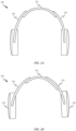
- FIG. 1A shows a front view of an exemplary set of over ear or on-ear headphones 100.
- Headphones 100 includes a band 102 that interacts with stems 104 and 106 to allow for adjustability of the size of headphones 100.
- stems 104 and 106 are configured to shift independently with respect to band 102 in order to accommodate multiple different head sizes. In this way, the position of earpieces 108 and 110 can be adjusted to position earpieces 108 and 110 directly over the ears of a user.
- FIG. 1B this type of configuration allows stems 104 and 106 to become mismatched with respect to band 102.
- the configuration shown in FIG. 1B can be less comfortable for a user and additionally lack cosmetic appeal.
- FIGS. 1A - 1B also show how stems 104 and 106 extend down to a central portion of earpieces 108 in order to allow earpieces 108 to rotate to accommodate the curvature of a user's head.
- the portions of stems 104 and 106 that extend down around earpieces 108 increase the diameters of earpieces 108.
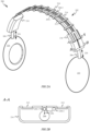
- the openings for wire loop 204 can be defined by low-friction bearings to prevent noticeable friction from impeding the motion of wire loop 204 through the openings.
- wire guides 210 define a path along which wire loop 204 extends between stem housings 216 and 218.
- Wire loop 204 is coupled to both stem 206 and stem 208 and functions to maintain a distance 120 between an earpiece 122 and stem housing 116 substantially the same as a distance 124 between earpiece 126 and stem housing 118.
- a first side 204-1 of wire loop 204 is coupled to stem 206 and a second side 204-2 of wire loop 204 is coupled to stem 208. Because opposite sides of the wire loop are attached to stems 206 and 208 movement of one of the stems results in movement of the other stem in the same direction.
- FIG. 2B shows a cross-sectional view of a portion of stem housing 116 in accordance with section line A-A.
- FIG. 2B shows how a protrusion 228 of stem 206 engages part of wire loop 204. Because protrusion 228 of stem 206 is coupled with wire loop 204, when a user of headphones 100 pulls earpiece 222 farther away from stem housing 216, wire loop 204 is also pulled causing wire loop 204 to circulate through headband 202. The circulation of wire loop 204 through headband 202 adjusts the position of earpieces 226, which is similarly coupled to wire loop 204 by a protrusion of stem 208.
- protrusion 228 can also be electrically coupled to wire loop 204.
- protrusion 228 can include an electrically conductive pathway 230 that electrically couples wire loop 204 to electrical components within earpiece 222.
- wire loop 204 can be formed from an electrically conductive material, so that signals can be transferred between components within earpieces 222 and 226 by way of wire loop 204.
- FIG. 2C shows another cross-sectional view of stem housing 116 in accordance with section line B-B.
- FIG. 2C shows how wire loop 204 engages pulley 232 within stem housing 216.
- Pulley 232 minimizes any friction generated by the movement of earpiece 222 closer or farther away from stem housing 216.
- wire loop 204 can be routed through a static bearing within stem housing 216.
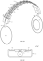
- FIG. 2D shows another perspective view of headphones 200.
- first side 204-1 and second side 204-2 of wire loop 204 shift laterally as they cross from one side of headband 202 to the other. This can be accomplished by the openings defined by wire guides 210 being gradually offset so that by the time sides 204-1 and 204-2 reach stem housing 218, second side 204-2 is centered and aligned with stem 208, as depicted in FIG. 2E .
- FIG. 2E shows how second side 204-2 is engaged by protrusion 234. Because stems 206 and 208 are attached to respective first and second sides of wire loop 204, pushing earpiece 226 towards stem housing 218 also results in earpiece 222 being pushed towards stem housing 216. Another advantage of the configuration depicted in FIGS. 2A - 2E is that regardless of the direction of travel of stems 206 and 208, wire loop 204 always stays in tension. This keeps the amount of force needed to extend or retract earpieces 222 and 226 consistent regardless of direction.
- FIGS. 2F - 2G show perspective views of headphones 250.
- Headphones 250 are similar to headphones 200 with the exception that only a single leaf spring 252 is used to connect stem housing 254 to stem housing 256.
- wire loop 258 can be positioned to either side of leaf spring 252.
- stems 260 and 262 can be positioned directly between the two sides of wire loop 258 and connected to one side of wire loop 258 by an arm of stems 260 and 262.
- FIGS. 2H and 2I show cross-sectional views of an interior portion of stem housings 254 and 256.
- FIG. 2H shows a cross-sectional view of stem housing 254 in accordance with section line D-D.
- FIG. 2H shows how stem 260 can include a laterally protruding arm 268 that engages wire loop 258. In this way, laterally protruding arm 268 couples stem 260 to wire loop 258 so that when earpiece 264 is moved earpiece 266 is kept in an equivalent position.
- FIG. 2I shows a cross-sectional view of stem housing 256 in accordance with section line E-E.
- FIG. 2I shows how wire loop 258 can be routed within stem housing 256 by pulleys 270 and 272. By routing wire loop 258 above stem 262 any interference between wire loop 258 and stem 206 can be avoided.
- FIG. 3A shows a flattened schematic view of another earpiece synchronization system that utilizes a loop 328 within a headband 330 (the rectangular shape is used merely to show the location of headband 330 and should not be construed as for exemplary purposes only) to keep a distance between each of earpieces 304 and 306 and headband 330 synchronized.
- Stem wires 332 and 334 couple respective earpieces 304 and 306 to loop 328.
- Stem wires 332 and 334 can be formed of metal and soldered to opposing sides of loop 328. Because stem wires 332 and 334 are coupled to opposing sides of loop 328, movement of earpiece 306 in direction 336 results in stem wire 332 moving in direction 338.
- FIG. 3B shows how moving earpiece 304 in direction 340 automatically moves earpiece 306 in direction 342 and farther away from headband 330. While not depicted it should be appreciated that headband 330 could include various reinforcement members to keep loop 328 and stem wires 332 and 334 in the depicted shapes.
- FIGS. 3C - 3D show a flattened schematic view of another earpiece synchronization system similar to the one depicted in FIGS. 3A - 3B .
- FIG. 3C shows how the ends of stems 344 and 346 can be coupled directly to each other without an intervening loop.
- stems 344 and 346 By extending stems 344 and 346 into a pattern, having a similar shape as loop 328, a similar outcome can be achieved without the need for an additional loop structure. Movement of stems 344 and 346 is assisted by reinforcement members 348, 350 and 352, which help to prevent buckling of stems 344 and 346 while the position of earpieces 304 and 306 are being adjusted.
- Reinforcement members 348-352 can define channels through which stems 344 and 346 smoothly pass.
- reinforcement member 352 While not defining a curved channel, reinforcement member 352 still serves an important purpose of limiting the direction of travel of the ends of stems 344 and 346 to directions 354 and 356. Movement in direction 356 results in earpieces moving toward headband 330, as depicted in FIG. 3D . Movement in direction 354 results in earpieces 304 and 306 moving farther away from headband 330.
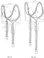
- FIGS. 3E - 3F show cutaway views of headphones 360 that are suitable for incorporation of either one of the earpiece synchronization systems depicted in FIGS. 3A - 3D .
- FIG 3E shows headphones 360 with earpieces retracted and stem wires 332 and 334 extending out of headband 330 to engage and synchronize a position of stem assembly 362 with a position of stem assembly 364.
- Stem 334 is depicted coupled to support structure 366 within stem assembly 364, which allows extension and retraction of stem 334 to keep stem assembly 362 synchronized with stem assembly 364.
- stem assembly 362 is disposed within a channel defined by headband 330, which allows stem assembly 362 to move relative to headband 330.
- data synchronization cable 368 can extend through headband 330 and wrap around a portion of both stem wire 334 and stem wire 332.
- data synchronization cable 356 is able to act as a reinforcement member to prevent buckling of stem wires 332 and 334.
- Data synchronization cable 356 is generally configured to exchange signals between earpieces 304 and 306 in order to keep audio precisely synchronized during playback operations of headphones 360.
- FIG. 3F shows how the coil configuration of data synchronization cable 368 accommodates extension of stem assemblies 362 and 364.
- Data synchronization cable 368 can have an exterior surface with a coating that allows stem wires 332 and 334 to slide through a central opening defined by the coils.
- FIG. 3F also shows how earpieces 304 and 306 maintain the same distance from a central portion of headband 330.
- FIGS. 3G - 3H show perspective views of the earpiece synchronization system depicted in FIGS. 3A - 3B in retracted and extended positions as well as a data synchronization cable 368.
- FIG. 3G shows how stem wire 332 includes an attachment feature 370 that at least partially surrounds a portion of loop 328. In this way, stem wire 332, stem wire 334 and support structures 366 move along with loop 328.
- FIG. 3G also shows a dashed line illustrating how a covering for headband 330 can at least partially conform with loop 328, stem wire 332 and stem wire 334.
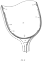
- FIG. 3I shows a portion of canopy structure 372 and how an earpiece synchronization system can be routed through reinforcement members 374 of canopy structure 372. Reinforcement members 374 help guide loop 328 and stem wire 332 along a desired path.
- canopy structure 372 can include a spring mechanism that helps keep earpieces secured to a user's ears.
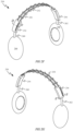
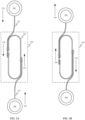
- FIGS. 4A - 4B show another way in which to limit the range of motion of a pair of headphones 900 using a low spring-rate band 902.
- FIG. 4A shows cable 904 in a slack state on account of earpieces 904 being pulled apart.
- the range of motion of low spring-rate band 902 can be limited by cable 904 achieving a similar function to the function of compression band 806, engaging as a result of function of tension instead of compression.
- Cable 904 is configured to extend between earpieces 906 and is coupled to each of earpieces 906 by anchoring features 908. Cable 904 can be held above low spring-rate band 902 by wire guides 910.
- Wire guides 910 can be similar to wire guides 210 depicted in FIGS.
- wire guides 910 are configured to elevate cable 904 above low spring-rate band 902. Bearings of wire guides 910 can prevent cable 904 from catching or becoming undesirably tangled. It should be noted that cable 904 and low spring-rate band 902 can be covered by a cosmetic cover. It should also be noted that in some embodiments, cable 904 could be combined with the embodiments shown in FIGS. 2A - 2G to produce headphones capable of synchronizing earpiece position and controlling the range of motion of the headphones.
- FIG. 4B shows how when earpieces 906 are brought closer together cable 904 tightens and eventually stops further movement of earpieces 906 closer together. In this way, a minimum distance 912 between earpieces 906 can be maintained that allows headphones 900 to be worn comfortably around the neck of a broad population of users without squeezing the neck of the user too tightly.
- Headphones include the following: a first earpiece; a second earpiece; and a headband coupling the first and second earpieces together and being configured to synchronize a movement of the first earpiece with a movement of the second earpiece such that a distance between the first earpiece and a center of the headband remains substantially equal to a distance between the second earpiece and the center of the headband.
- the headband comprises a loop of cable routed therethrough.
- a first stem of the first earpiece is coupled to the loop of cable and a second stem of the second earpiece is coupled to the loop of cable.
- the loop of cable is configured to route an electrical signal from the first earpiece to the second earpiece.
- the headband includes two parallel leaf springs defining a shape of the headband.
- the headband includes a loop of wire disposed within the headband, a first stem wire coupling the first earpiece to a first side of the loop of wire, and a second stem wire coupling the second earpiece to a second side of the loop of wire.
- the headphones also include a data synchronization cable extending from the first earpiece to the second earpiece through a channel defined by the headband, the data synchronization cable carrying signals between electrical components of the first and second earpieces.
- a first portion of the data synchronization cable is coiled around the first stem wire and a second portion of the data synchronization cable is coiled around the second stem wire.
- Headphones include the following: a headband having a first end and a second end opposite the first end; a first earpiece coupled to the headband a first distance from the first end; a second earpiece coupled to the headband a second distance from the second end; and a cable routed through the headband and mechanically coupling the first earpiece to the second earpiece, the cable being configured to maintain the first distance substantially the same as the second distance by changing the first distance in response to a change in the second distance.
- the cable is arranged in a loop and the first earpiece is coupled to a first side of the loop and the second earpiece is coupled to a second side of the loop.
- the headphones also include stem housings coupled to opposing ends of the headband, each of the stem housings enclosing a pulley about which the cable is wrapped.
- the headphones also include wire guides distributed across the headband and defining a path of the cable through the headband.
- Headphones include the following: a first earpiece; a second earpiece; a headband assembly coupling the first and second earpieces together and comprising an earpiece synchronization system, the earpiece synchronization system configured to change a first distance between the first earpiece and the headband assembly concurrently with a change in a second distance between the second earpiece and the headband assembly.
- the headphones also include first and second members coupled to opposing ends of the headband assembly, each of the first and second members being configured to telescope relative to a channel defined by a respective end of the headband assembly.
- the earpiece synchronization system includes a first stem wire coupled to the first earpiece and a second stem wire coupled to the second earpiece.
- the first stem wire is coupled to the second stem wire in a channel disposed within a central region of the headband assembly.
- the headphones also include a reinforcement member disposed within the headband assembly and defining the channel within which the first and second stem wires are coupled together.
- the earpiece synchronization system includes a first stem wire having a first end coupled to the first earpiece and a second end coupled to a second end of the second stem wire and wherein a first end of the second stem wire is coupled to the second earpiece.
- the second end of the first stem wire is oriented in the same direction as the second end of the second stem wire.
Landscapes
- Physics & Mathematics (AREA)
- Engineering & Computer Science (AREA)
- Acoustics & Sound (AREA)
- Signal Processing (AREA)
- Health & Medical Sciences (AREA)
- Otolaryngology (AREA)
- Headphones And Earphones (AREA)
- Circuit For Audible Band Transducer (AREA)
- Stereophonic Arrangements (AREA)
Claims (10)
- Kopfhörer (200), umfassend:einen ersten Ohrhörer (222);einen zweiten Ohrhörer (226); undein Kopfband (202), wobei das Kopfband (202) dadurch gekennzeichnet ist, dass es Stielgehäuse (216, 218), die den ersten und den zweiten Ohrhörer (222, 226) mit gegenüberliegenden Enden des Kopfbügels (202) verbinden, und eine Kabelschleife (204) umfasst, die durch das Kopfband (202) geführt und um Riemenscheiben (232) gewickelt ist, die in jedem der Stielgehäuse (216, 218) angeordnet sind, wobei die Kabelschleife (204) so konfiguriert ist, dass sie eine Bewegung des ersten Ohrhörers (222) mit einer Bewegung des zweiten Ohrhörers (226) synchronisiert, so dass ein Abstand zwischen dem ersten Ohrhörer (222) und einer Mitte des Kopfbandes (202) im Wesentlichen gleich einem Abstand zwischen dem zweiten Ohrhörer (226) und der Mitte des Kopfbandes (202) bleibt; gekennzeichnet durchDrahtführungen (210), die über das Kopfband (202) verteilt sind und einen Weg der Kabelschleife (204) durch das Kopfband (202) definieren, wobei die Kabelschleife (204) mit dem ersten und dem zweiten Ohrhörer (222, 226) zusammenwirkt, um den Abstand zwischen dem ersten Ohrhörer (222) und einer Mitte des Kopfbandes (202) im Wesentlichen gleich dem Abstand zwischen dem zweiten Ohrhörer (226) und der Mitte des Kopfbandes (202) zu halten;zwei parallele Blattfedern (212, 214), die eine Form des Kopfbandes (202) definieren; undwobei jede der Drahtführungen (210) Öffnungen aufweist, durch die gegenüberliegende Seiten der Kabelschleife (204) und der Blattfedern (212, 214) hindurchgehen können.
- Kopfhörer (200) nach Anspruch 1, wobei die Kabelschleife (204) so konfiguriert ist, dass sie ein elektrisches Signal von dem ersten Ohrhörer (222) zu dem zweiten Ohrhörer (226) leitet.
- Kopfhörer (200) nach Anspruch 1 oder 2, wobei ein erster Schaft (206) der ersten Ohrhörer (222) mit der Kabelschleife (204) und ein zweiter Schaft (208) der zweiten Ohrhörer (226) mit der Kabelschleife (204) verbunden ist.
- Kopfhörer (200) nach Anspruch 3, wobei der erste Schaft (206) mit einem ersten Ende der Kabelschleife (204) verbunden ist und der zweite Schaft (208) mit einem zweiten Ende der Kabelschleife (204) gegenüber dem ersten Ende verbunden ist.
- Kopfhörer (200) nach Anspruch 1, wobei die Kabelschleife (204, 328) innerhalb des Kopfbandes (202, 330) angeordnet ist, wobei ein erster Stangendraht (332) den ersten Ohrhörer (222, 304) mit einer ersten Seite der Kabelschleife (204, 328) verbindet, und ein zweiter Stangendraht (324) den zweiten Ohrhörer(226, 306) mit einer zweiten Seite der Kabelschleife (204) verbindet.
- Kopfhörer (200) nach Anspruch 1, ferner umfassend: ein Datensynchronisationskabel (368), das sich von dem ersten Ohrhörer (222) zu dem zweiten Ohrhörer (226) durch einen von dem Kopfband (202) definierten Kanal erstreckt, wobei das Datensynchronisationskabel (368) Signale zwischen elektrischen Komponenten der ersten und zweiten Ohrhörer (222, 226) überträgt.
- Kopfhörer (200) nach Anspruch 6, wobei ein erster Teil des Datensynchronisationskabels (368) um den ersten Stangendraht (362) und ein zweiter Teil des Datensynchronisationskabels (368) um den zweiten Stangendraht (364) gewickelt ist.
- Kopfhörer (200) nach einem der vorhergehenden Ansprüche, ferner mit einem ersten und einem zweiten Stiel (206, 208), die mit gegenüberliegenden Enden der Kopfbandanordnung gekoppelt sind, wobei der erste und der zweite Schaft (206, 208) jeweils so konfiguriert sind, dass sie relativ zu einem durch ein jeweiliges Ende der Kopfbandanordnung definierten Kanal teleskopierbar sind.
- Kopfhörer (200) nach Anspruch 8, wobei der erste Schaft (206) und der zweite Schaft (208) beide mit einem Kabel (204) gekoppelt sind, das innerhalb der Kopfbandanordnung angeordnet ist und den Abstand zwischen dem ersten Ohrhörer (222) und einer Mitte des Kopfbandes im Wesentlichen gleich dem Abstand zwischen dem zweiten Ohrhörer (226) und der Mitte des Kopfbandes (202) hält.
- Kopfhörer (200) nach Anspruch 9, wobei das Kabel (204) in einer Schleife innerhalb der Kopfbandanordnung angeordnet ist.
Priority Applications (1)
| Application Number | Priority Date | Filing Date | Title |
|---|---|---|---|
| EP25158659.0A EP4531433A3 (de) | 2016-09-23 | 2017-09-22 | Synchronisierte teleskopische kopfhörer |
Applications Claiming Priority (12)
| Application Number | Priority Date | Filing Date | Title |
|---|---|---|---|
| US201662398520P | 2016-09-23 | 2016-09-23 | |
| US201662398847P | 2016-09-23 | 2016-09-23 | |
| US201662398517P | 2016-09-23 | 2016-09-23 | |
| US201662398890P | 2016-09-23 | 2016-09-23 | |
| US201662398854P | 2016-09-23 | 2016-09-23 | |
| US201662398937P | 2016-09-23 | 2016-09-23 | |
| US201662398895P | 2016-09-23 | 2016-09-23 | |
| US201662398899P | 2016-09-23 | 2016-09-23 | |
| US201662398929P | 2016-09-23 | 2016-09-23 | |
| US201662398946P | 2016-09-23 | 2016-09-23 | |
| EP17778143.2A EP3516884B1 (de) | 2016-09-23 | 2017-09-22 | Kopfhörer |
| PCT/US2017/052978 WO2018057907A1 (en) | 2016-09-23 | 2017-09-22 | Headphones |
Related Parent Applications (2)
| Application Number | Title | Priority Date | Filing Date |
|---|---|---|---|
| EP17778143.2A Division EP3516884B1 (de) | 2016-09-23 | 2017-09-22 | Kopfhörer |
| EP17778143.2A Division-Into EP3516884B1 (de) | 2016-09-23 | 2017-09-22 | Kopfhörer |
Related Child Applications (2)
| Application Number | Title | Priority Date | Filing Date |
|---|---|---|---|
| EP25158659.0A Division EP4531433A3 (de) | 2016-09-23 | 2017-09-22 | Synchronisierte teleskopische kopfhörer |
| EP25158659.0A Division-Into EP4531433A3 (de) | 2016-09-23 | 2017-09-22 | Synchronisierte teleskopische kopfhörer |
Publications (2)
| Publication Number | Publication Date |
|---|---|
| EP3565271A1 EP3565271A1 (de) | 2019-11-06 |
| EP3565271B1 true EP3565271B1 (de) | 2025-03-26 |
Family
ID=60002130
Family Applications (4)
| Application Number | Title | Priority Date | Filing Date |
|---|---|---|---|
| EP19178742.3A Active EP3565274B1 (de) | 2016-09-23 | 2017-09-22 | Automatische links/rechts-bestimmung einer ohrmuschel |
| EP25158659.0A Pending EP4531433A3 (de) | 2016-09-23 | 2017-09-22 | Synchronisierte teleskopische kopfhörer |
| EP17778143.2A Active EP3516884B1 (de) | 2016-09-23 | 2017-09-22 | Kopfhörer |
| EP19179498.1A Active EP3565271B1 (de) | 2016-09-23 | 2017-09-22 | Synchronisierte teleskopische kopfhörer |
Family Applications Before (3)
| Application Number | Title | Priority Date | Filing Date |
|---|---|---|---|
| EP19178742.3A Active EP3565274B1 (de) | 2016-09-23 | 2017-09-22 | Automatische links/rechts-bestimmung einer ohrmuschel |
| EP25158659.0A Pending EP4531433A3 (de) | 2016-09-23 | 2017-09-22 | Synchronisierte teleskopische kopfhörer |
| EP17778143.2A Active EP3516884B1 (de) | 2016-09-23 | 2017-09-22 | Kopfhörer |
Country Status (6)
| Country | Link |
|---|---|
| US (3) | US10848847B2 (de) |
| EP (4) | EP3565274B1 (de) |
| JP (7) | JP6902605B2 (de) |
| KR (6) | KR102393076B1 (de) |
| CN (9) | CN112839282B (de) |
| WO (1) | WO2018057907A1 (de) |
Families Citing this family (22)
| Publication number | Priority date | Publication date | Assignee | Title |
|---|---|---|---|---|
| KR102393076B1 (ko) | 2016-09-23 | 2022-05-03 | 애플 인크. | 동기화된 텔레스코핑 헤드폰 |
| US11323793B2 (en) | 2016-09-23 | 2022-05-03 | Apple Inc. | Synchronized telescoping headphones |
| US11102567B2 (en) | 2016-09-23 | 2021-08-24 | Apple Inc. | Foldable headphones |
| US10945076B2 (en) | 2016-09-23 | 2021-03-09 | Apple Inc. | Low spring-rate band |
| KR102386280B1 (ko) | 2017-11-20 | 2022-04-14 | 애플 인크. | 헤드폰 |
| KR102550563B1 (ko) * | 2018-04-02 | 2023-07-03 | 애플 인크. | 헤드폰 |
| US10743106B2 (en) * | 2018-08-09 | 2020-08-11 | Bose Corporation | Headphone earcup mount in continuous headband-spring headphone system |
| US11006206B2 (en) * | 2019-06-07 | 2021-05-11 | Microsoft Technology Licensing, Llc | Ergonomic headphone device |
| WO2021148908A1 (en) * | 2020-01-21 | 2021-07-29 | 3M Innovative Properties Company | Cable compaction system for protective personal equipment |
| JP7567183B2 (ja) | 2020-03-24 | 2024-10-16 | 株式会社Jvcケンウッド | 音入出力制御装置、音入出力制御方法、及びプログラム |
| KR102745698B1 (ko) * | 2020-08-07 | 2024-12-24 | 삼성전자주식회사 | 관성 센서를 이용하여 전자 장치의 착용 상태를 감지하는 전자 장치 및 그 제어 방법 |
| CN111836173B (zh) * | 2020-08-26 | 2024-10-18 | 深圳市星科启创新科技有限公司 | 一种锁合式直杆tws蓝牙耳机 |
| US11457300B2 (en) | 2020-09-16 | 2022-09-27 | Apple Inc. | Support structure for earpiece cushion |
| US11190878B1 (en) | 2020-09-16 | 2021-11-30 | Apple Inc. | Headphones with on-head detection |
| US11184696B1 (en) | 2020-09-16 | 2021-11-23 | Apple Inc. | Wireless headphones with slot antenna |
| US11272279B1 (en) | 2020-09-16 | 2022-03-08 | Apple Inc. | Headphones with off-center pivoting earpiece |
| KR102370433B1 (ko) * | 2020-09-16 | 2022-03-04 | 애플 인크. | 오프-센터 피봇 이어피스를 갖는 헤드폰 |
| US11272280B1 (en) | 2020-09-16 | 2022-03-08 | Apple Inc. | Earpiece with cushion retention |
| KR102864051B1 (ko) * | 2021-04-07 | 2025-09-24 | 삼성전자주식회사 | 무선 이어폰 장치 및 그 제어 방법 |
| US11588459B1 (en) * | 2021-08-03 | 2023-02-21 | GM Global Technology Operations LLC | Vehicle audio control based on sensed physical changes in vehicle configuration |
| US11985469B2 (en) * | 2022-04-29 | 2024-05-14 | Dell Products Lp | System and method for enhanced wearable hearing device command instruction manual input |
| EP4533816A1 (de) * | 2022-05-30 | 2025-04-09 | GN Hearing A/S | Hörgerät |
Citations (1)
| Publication number | Priority date | Publication date | Assignee | Title |
|---|---|---|---|---|
| WO2016002150A1 (ja) * | 2014-07-02 | 2016-01-07 | ソニー株式会社 | ヘッドホン |
Family Cites Families (134)
| Publication number | Priority date | Publication date | Assignee | Title |
|---|---|---|---|---|
| GB223043A (en) * | 1923-04-10 | 1924-10-10 | Leonard Dunwoodie | Improvements in and connected with head-piece telephones |
| US2924672A (en) | 1958-08-26 | 1960-02-09 | Roanwell Corp | Headset |
| AT297111B (de) | 1970-04-08 | 1972-03-10 | Akg Akustische Kino Geraete | Bügel für Kopfhörer |
| JPS536220B2 (de) | 1973-05-14 | 1978-03-06 | ||
| AT321388B (de) | 1973-06-01 | 1975-03-25 | A K G Akustische U Kino Geraet | Kopfhörer |
| US3902120A (en) | 1974-05-20 | 1975-08-26 | Dyn Electronics Inc | Combination radio receiver and stereo headphones |
| US4027113A (en) * | 1974-09-12 | 1977-05-31 | Nippon Gakki Seizo Kabushiki Kaisha | Headphone |
| JPS5170528U (de) * | 1974-11-29 | 1976-06-03 | ||
| JPS536220U (de) * | 1976-07-01 | 1978-01-20 | ||
| NL7804041A (nl) | 1978-04-17 | 1979-10-19 | Philips Nv | Stethoscopische oortelefoon. |
| JPS575985Y2 (de) * | 1978-08-01 | 1982-02-04 | ||
| AT370581B (de) * | 1981-07-20 | 1983-04-11 | Akg Akustische Kino Geraete | Kopfhoererbuegel |
| DK148869C (da) | 1983-04-15 | 1986-09-22 | Bang & Olufsen As | Hovedtelefon |
| US4609786A (en) | 1983-10-13 | 1986-09-02 | Nippon Gakki Seizo Kabushiki Kaisha | Band and the headphone utilizing the same |
| JPS6374891U (de) * | 1986-10-31 | 1988-05-18 | ||
| US5056161A (en) * | 1989-09-26 | 1991-10-15 | Bose Corporation | Headset having reduced width nested bands which are grasped by earcup supporting block |
| US5099519A (en) | 1990-05-29 | 1992-03-24 | Yu Guan | Headphones |
| US5117465A (en) * | 1991-03-15 | 1992-05-26 | Unex Corporation | Earphone with adjustable headband with progressively shallow detents |
| JP2733392B2 (ja) | 1991-07-30 | 1998-03-30 | 松下電送株式会社 | ディスクドライブ装置のヘッド送り制御装置 |
| US5469505A (en) * | 1992-07-08 | 1995-11-21 | Acs Wireless, Inc. | Communications headset having a ball joint-mounted receiver assembly |
| US5375174A (en) * | 1993-07-28 | 1994-12-20 | Noise Cancellation Technologies, Inc. | Remote siren headset |
| US5625903A (en) | 1996-02-26 | 1997-05-06 | Schultz; Michael A. | Headband with adjustable speaker supporting means |
| US6333982B1 (en) * | 1996-04-01 | 2001-12-25 | Bose Corporation | Headset adjusting |
| US5862241A (en) * | 1996-05-03 | 1999-01-19 | Telex Communications, Inc. | Adjustable headset |
| JP3778999B2 (ja) | 1996-07-08 | 2006-05-24 | フオスター電機株式会社 | ヘッドホン装置 |
| TW449222U (en) * | 1999-12-22 | 2001-08-01 | Juang Ching Guo | Ear phone structure modification |
| US20040011149A1 (en) * | 2002-04-03 | 2004-01-22 | David Carroll | Integrated angular and radial position sensor |
| US6724906B2 (en) | 2002-05-07 | 2004-04-20 | Alex Naksen | Adjustable headphone |
| US6629579B1 (en) * | 2002-10-03 | 2003-10-07 | Twd-Acoustic Products Ltd. | Headphones/earmuffs |
| AT414198B (de) * | 2003-01-31 | 2006-10-15 | Akg Acoustics Gmbh | Kopfhörer |
| US7171698B2 (en) * | 2003-02-07 | 2007-02-06 | Jackson Products, Inc. | Earmuff having anatomically correct ear cups |
| JP3838229B2 (ja) | 2003-08-13 | 2006-10-25 | ソニー株式会社 | ヘッドホン |
| KR100630126B1 (ko) * | 2004-12-21 | 2006-09-28 | 삼성전자주식회사 | 귀 착용 타입 무선 헤드셋 폰 |
| US7388960B2 (en) * | 2005-01-19 | 2008-06-17 | Ching-Chang Kuo | Multimedia speaker headphone |
| JP4467459B2 (ja) | 2005-04-22 | 2010-05-26 | アルパイン株式会社 | オーディオ信号制御方法及び装置 |
| JP4470845B2 (ja) * | 2005-09-05 | 2010-06-02 | ソニー株式会社 | ヘッドホン及びヘッドホン載置装置 |
| US20070258614A1 (en) * | 2006-05-03 | 2007-11-08 | Altec Lansing, A Division Of Plantronics, Inc. | Headphone and portable speaker system |
| WO2008004274A1 (en) * | 2006-07-03 | 2008-01-10 | Frey Co., Ltd. | Voice transmission device |
| JP4269181B2 (ja) * | 2006-09-06 | 2009-05-27 | ソニー株式会社 | ヘッドホン |
| US8085966B2 (en) * | 2007-01-10 | 2011-12-27 | Allan Amsel | Combined headphone set and portable speaker assembly |
| US8050444B2 (en) * | 2007-01-19 | 2011-11-01 | Dale Trenton Smith | Adjustable mechanism for improving headset comfort |
| KR101362334B1 (ko) * | 2007-08-09 | 2014-02-12 | 삼성전자주식회사 | 외부 스피커로 사용 가능한 헤드셋 및 헤드셋의 스피커출력 조정 방법 |
| CN201100960Y (zh) | 2007-08-24 | 2008-08-13 | 中名(东莞)电子有限公司 | 一种旋转折叠式耳机 |
| JP2009105554A (ja) | 2007-10-22 | 2009-05-14 | Sony Corp | ヘッドホン |
| NZ563243A (en) * | 2007-11-07 | 2010-06-25 | Objective Concepts Nz Ltd | Headset |
| JP2009171342A (ja) | 2008-01-17 | 2009-07-30 | Sony Corp | ヘッドホン |
| US8170261B2 (en) * | 2008-02-20 | 2012-05-01 | Logitech Europe S.A. | Personal audio set with adjustable force mechanisms |
| US8270658B2 (en) * | 2008-04-28 | 2012-09-18 | Hearing Enhancement Group | Position sensing apparatus and method for active headworn device |
| AU2009201813B2 (en) * | 2008-05-14 | 2013-08-29 | Nixon, Inc. | Headphones |
| US8055006B2 (en) * | 2008-06-23 | 2011-11-08 | Koss Corporation | Soft-opening hinge and headphone including same |
| WO2010038299A1 (ja) * | 2008-10-02 | 2010-04-08 | パイオニア株式会社 | ヘッドホン |
| KR101248841B1 (ko) * | 2008-11-04 | 2013-03-29 | 크레신 주식회사 | 헤드폰 |
| US20120070027A1 (en) * | 2009-03-02 | 2012-03-22 | Bettina Ridler | Headset With Magnetically Attached Ear Pad |
| JP2011015235A (ja) * | 2009-07-02 | 2011-01-20 | Sony Corp | ヘッドホン |
| TWM370905U (en) * | 2009-08-25 | 2009-12-11 | Gamma Inc | Headphone and the rotating axle |
| BR112012004527B1 (pt) * | 2009-09-10 | 2019-02-26 | Koss Corporation | Aparelho e método para sincronizar a reprodução de áudio |
| US9301039B2 (en) | 2010-01-04 | 2016-03-29 | Apple Inc. | Headphone |
| WO2011085096A2 (en) * | 2010-01-06 | 2011-07-14 | Skullcandy, Inc. | Dj mixing headphones |
| US9467780B2 (en) * | 2010-01-06 | 2016-10-11 | Skullcandy, Inc. | DJ mixing headphones |
| DE102010006927B4 (de) * | 2010-02-04 | 2021-05-27 | Sennheiser Electronic Gmbh & Co. Kg | Headset und Hörer |
| US20130038458A1 (en) * | 2010-04-23 | 2013-02-14 | Nokia Corporation | Apparatus and a method for causing a change in the state of a headset |
| US8503711B2 (en) | 2010-05-20 | 2013-08-06 | Michael Flynn | Hat mounted music system |
| JP2012079082A (ja) | 2010-10-01 | 2012-04-19 | Sony Corp | 入力装置 |
| US20120140973A1 (en) | 2010-12-02 | 2012-06-07 | Robert Olodort | Collapsible headphone |
| US9084055B2 (en) * | 2011-01-03 | 2015-07-14 | Apple Inc. | Audio listening system |
| US20120269374A1 (en) * | 2011-01-05 | 2012-10-25 | Noel Lee | Automatically adjusting headphones |
| CN202004947U (zh) * | 2011-01-24 | 2011-10-05 | 陈王胜 | 播放器 |
| CN102231866B (zh) * | 2011-04-22 | 2013-12-18 | 浙江魔杰电子股份有限公司 | 耳罩可相对于头带转动与伸缩的耳机 |
| CN202004940U (zh) * | 2011-04-22 | 2011-10-05 | 浙江魔杰电子有限公司 | 耳罩可相对于头带转动与伸缩的耳机 |
| CN201986123U (zh) * | 2011-04-29 | 2011-09-21 | 浙江魔杰电子有限公司 | 耳罩距离可调的头戴式耳机 |
| WO2013027236A1 (ja) | 2011-08-22 | 2013-02-28 | 三菱電機株式会社 | 移動体用情報機器 |
| JP2013138349A (ja) * | 2011-12-28 | 2013-07-11 | D & M Holdings Inc | ヘッドホン |
| US20130202126A1 (en) * | 2012-02-08 | 2013-08-08 | Jinsaun Chen | Headphones activated by rotation of an ear cup |
| US8755555B2 (en) * | 2012-04-13 | 2014-06-17 | The Echo Design Group, Inc. | Adjustable and convertible audio headphones |
| US20130279724A1 (en) * | 2012-04-19 | 2013-10-24 | Sony Computer Entertainment Inc. | Auto detection of headphone orientation |
| CN202750206U (zh) * | 2012-06-29 | 2013-02-20 | 深圳雷柏科技股份有限公司 | 一种折叠式耳机结构 |
| CN202998400U (zh) | 2012-08-08 | 2013-06-12 | 深圳市冠旭电子有限公司 | 可透气的头戴式耳机 |
| KR101353588B1 (ko) * | 2012-08-24 | 2014-01-23 | 삼본정밀전자(주) | 헤드폰 조립체 |
| GB201215554D0 (en) | 2012-08-31 | 2012-10-17 | Teca Technology Ltd | Headphones and headsets |
| US8605935B1 (en) | 2012-09-06 | 2013-12-10 | Wen-Tse HUANG | Headphones with a pair of glasses |
| CN103686506B (zh) * | 2012-09-17 | 2018-02-02 | 技嘉科技股份有限公司 | 头戴式耳机装置 |
| CN202799062U (zh) * | 2012-09-18 | 2013-03-13 | 深圳市颂尼科科技有限公司 | 可调卡位的耳机 |
| US9113246B2 (en) * | 2012-09-20 | 2015-08-18 | International Business Machines Corporation | Automated left-right headphone earpiece identifier |
| US8737668B1 (en) | 2013-01-23 | 2014-05-27 | Koss Corporation | Headband for personal speakers |
| US8861770B2 (en) | 2013-01-23 | 2014-10-14 | Koss Corporation | Headband for personal speakers |
| US9344794B1 (en) | 2013-03-08 | 2016-05-17 | Ideavillage Products Corp. | Multi mode headphone with folding headband |
| US9161117B2 (en) | 2013-03-08 | 2015-10-13 | Idea Village Products Corp. | Multi-mode listening apparatus |
| CN203233530U (zh) * | 2013-04-16 | 2013-10-09 | 苏州圣杰特数码科技有限公司 | 一种旋转的立体声耳机 |
| WO2014207979A1 (ja) | 2013-06-28 | 2014-12-31 | ソニー株式会社 | ヘッドホン |
| JP6185323B2 (ja) * | 2013-07-25 | 2017-08-23 | フォスター電機株式会社 | ヘッドホン |
| JP2015037246A (ja) * | 2013-08-13 | 2015-02-23 | ソニー株式会社 | ヘッドフォン型音響装置およびその制御方法 |
| JP6280709B2 (ja) | 2013-08-30 | 2018-02-14 | 秋山 英彦 | 頭部装着具及び調整装置 |
| WO2015087431A1 (ja) | 2013-12-12 | 2015-06-18 | オンキヨー株式会社 | ヘッドホン装置 |
| CN203675282U (zh) | 2013-12-26 | 2014-06-25 | 东莞市今联实业有限公司 | 一种可折叠头戴耳机 |
| US9867571B2 (en) * | 2014-01-06 | 2018-01-16 | Interaxon Inc. | Wearable apparatus for brain sensors |
| DK2892246T3 (da) * | 2014-01-07 | 2020-01-02 | Sennheiser Communications As | Hovedtelefoner med passage over hovedet |
| US9298994B2 (en) * | 2014-01-09 | 2016-03-29 | Harman International Industries, Inc. | Detecting visual inattention based on eye convergence |
| DK3094199T3 (da) * | 2014-01-14 | 2019-09-30 | Gentex Corp | Drejearmsenhed til hjelmmonteret headset |
| US9445182B2 (en) * | 2014-02-04 | 2016-09-13 | David Cohen | Headphones with rotatable ear cup |
| US9148717B2 (en) | 2014-02-21 | 2015-09-29 | Alpha Audiotronics, Inc. | Earbud charging case |
| US9609415B2 (en) * | 2014-03-26 | 2017-03-28 | Bose Corporation | Headphones with cable management |
| CN103945295A (zh) | 2014-03-27 | 2014-07-23 | 广东欧珀移动通信有限公司 | 一种头戴式耳机 |
| CN104023105A (zh) | 2014-06-13 | 2014-09-03 | 广东欧珀移动通信有限公司 | 一种移动终端摄像头角度旋转检测装置及其检测方法 |
| CN105208475A (zh) | 2014-06-30 | 2015-12-30 | Gn奈康有限公司 | 耳机 |
| KR102163919B1 (ko) * | 2014-06-30 | 2020-10-12 | 엘지전자 주식회사 | 무선음향기기 |
| US9838776B2 (en) * | 2014-07-02 | 2017-12-05 | Sonetics Holdings, Inc. | Restricted ball and socket joint for headset earcup |
| TW201603589A (zh) * | 2014-07-09 | 2016-01-16 | 宏碁股份有限公司 | 耳機及其聲道控制方法 |
| CN104301826A (zh) * | 2014-10-15 | 2015-01-21 | 雷东玉 | 折叠无线充电耳麦系统 |
| CN105578330A (zh) | 2014-10-15 | 2016-05-11 | 深圳富泰宏精密工业有限公司 | 耳机夹持装置及应用该耳机夹持装置的耳机组件 |
| JP6596680B2 (ja) | 2014-11-18 | 2019-10-30 | 株式会社オーディオテクニカ | ヘッドホンの結線構造およびヘッドホン |
| CN104469624B (zh) * | 2014-12-16 | 2017-06-30 | 广东欧珀移动通信有限公司 | 耳机声道切换方法、系统、电子设备以及耳机 |
| CN104618830A (zh) * | 2014-12-31 | 2015-05-13 | 深圳市佳骏兴科技有限公司 | 头梁同步滑动装置及头戴式耳机 |
| US9522086B2 (en) * | 2015-01-06 | 2016-12-20 | Honeywell International Inc. | Headband folding mechanism allowing two axis folding directions |
| CN107209069B (zh) | 2015-02-03 | 2021-09-28 | 3M创新有限公司 | 用于听力保护器的舒适度提高的头带 |
| US9672707B2 (en) * | 2015-03-12 | 2017-06-06 | Alarm.Com Incorporated | Virtual enhancement of security monitoring |
| US9749727B2 (en) | 2015-06-18 | 2017-08-29 | Plantronics, Inc. | Folding headset earpiece |
| US10219068B2 (en) * | 2015-07-16 | 2019-02-26 | Voyetra Turtle Beach, Inc. | Headset with major and minor adjustments |
| US9729954B2 (en) | 2015-08-07 | 2017-08-08 | New Audio LLC | Audio headset having internal cord management features and related technology |
| CN205142456U (zh) | 2015-09-17 | 2016-04-06 | 深圳市冠旭电子有限公司 | 发声单元角度可调式耳机 |
| CN205142459U (zh) * | 2015-10-21 | 2016-04-06 | 深圳市冠旭电子有限公司 | 耳机支架的伸缩结构及具有该结构的头戴式耳机 |
| KR101637369B1 (ko) * | 2015-11-16 | 2016-07-07 | 엘지전자 주식회사 | 무선음향기기 |
| JP2017098869A (ja) * | 2015-11-27 | 2017-06-01 | 株式会社オーディオテクニカ | ヘッドホン |
| CN105554603B (zh) | 2015-12-04 | 2019-11-15 | 魅族科技(中国)有限公司 | 耳机及连杆组件 |
| CN205450450U (zh) * | 2015-12-29 | 2016-08-10 | 深圳市柔宇科技有限公司 | 头戴式显示设备的调节机构及头戴式显示设备 |
| US10178463B2 (en) * | 2016-03-07 | 2019-01-08 | Apple Inc. | Headphones |
| CN105812977B (zh) | 2016-04-06 | 2019-03-15 | 贵州翔通科技实业有限公司 | 伸缩旋转式耳机 |
| EP3476132B1 (de) * | 2016-06-22 | 2022-10-26 | Dolby Laboratories Licensing Corporation | Kopfhörer und kopfhörersysteme |
| KR102393076B1 (ko) | 2016-09-23 | 2022-05-03 | 애플 인크. | 동기화된 텔레스코핑 헤드폰 |
| US11102567B2 (en) | 2016-09-23 | 2021-08-24 | Apple Inc. | Foldable headphones |
| US10264341B2 (en) * | 2017-01-20 | 2019-04-16 | Bose Corporation | Magnetic pivot sensor for headset microphone |
| US10129632B2 (en) * | 2017-02-01 | 2018-11-13 | Bose Corporation | Headphone |
| US10334352B2 (en) * | 2017-09-30 | 2019-06-25 | Bose Corporation | Headphone pivot joint |
| KR102386280B1 (ko) | 2017-11-20 | 2022-04-14 | 애플 인크. | 헤드폰 |
| JP7087757B2 (ja) | 2018-07-18 | 2022-06-21 | 株式会社Jvcケンウッド | ヘッドホン |
-
2017
- 2017-09-22 KR KR1020217015409A patent/KR102393076B1/ko active Active
- 2017-09-22 CN CN202110242815.0A patent/CN112839282B/zh active Active
- 2017-09-22 KR KR1020227014204A patent/KR102566388B1/ko active Active
- 2017-09-22 WO PCT/US2017/052978 patent/WO2018057907A1/en not_active Ceased
- 2017-09-22 CN CN201910341349.4A patent/CN110062307B/zh active Active
- 2017-09-22 KR KR1020197008043A patent/KR102208860B1/ko active Active
- 2017-09-22 CN CN201910341357.9A patent/CN110012380B/zh active Active
- 2017-09-22 CN CN202110242819.9A patent/CN112839283B/zh active Active
- 2017-09-22 EP EP19178742.3A patent/EP3565274B1/de active Active
- 2017-09-22 CN CN201910341358.3A patent/CN109922400B/zh active Active
- 2017-09-22 EP EP25158659.0A patent/EP4531433A3/de active Pending
- 2017-09-22 US US16/335,846 patent/US10848847B2/en active Active
- 2017-09-22 KR KR1020197009018A patent/KR102211508B1/ko active Active
- 2017-09-22 CN CN201910341350.7A patent/CN110062312B/zh active Active
- 2017-09-22 EP EP17778143.2A patent/EP3516884B1/de active Active
- 2017-09-22 CN CN202110899469.3A patent/CN113596667B/zh active Active
- 2017-09-22 CN CN202411203906.3A patent/CN119110199A/zh active Pending
- 2017-09-22 EP EP19179498.1A patent/EP3565271B1/de active Active
- 2017-09-22 CN CN201780058416.0A patent/CN109792579B/zh active Active
- 2017-09-22 JP JP2019515893A patent/JP6902605B2/ja active Active
- 2017-09-22 KR KR1020217002922A patent/KR102359286B1/ko active Active
- 2017-09-22 KR KR1020197009025A patent/KR102258036B1/ko active Active
-
2019
- 2019-03-22 US US16/362,386 patent/US11184695B2/en active Active
- 2019-04-02 JP JP2019070684A patent/JP6878488B2/ja active Active
- 2019-04-02 JP JP2019070683A patent/JP6874047B2/ja active Active
-
2020
- 2020-10-15 US US17/071,819 patent/US11330354B2/en active Active
-
2021
- 2021-06-21 JP JP2021102593A patent/JP2021170779A/ja active Pending
- 2021-06-21 JP JP2021102592A patent/JP7216147B2/ja active Active
-
2023
- 2023-01-19 JP JP2023006677A patent/JP7523607B2/ja active Active
-
2024
- 2024-07-16 JP JP2024113567A patent/JP2024153691A/ja active Pending
Patent Citations (1)
| Publication number | Priority date | Publication date | Assignee | Title |
|---|---|---|---|---|
| WO2016002150A1 (ja) * | 2014-07-02 | 2016-01-07 | ソニー株式会社 | ヘッドホン |
Also Published As
Similar Documents
| Publication | Publication Date | Title |
|---|---|---|
| EP3565271B1 (de) | Synchronisierte teleskopische kopfhörer | |
| US11477575B2 (en) | Headphones | |
| US11109141B2 (en) | Seamless pivot for head-worn audio devices | |
| US11102567B2 (en) | Foldable headphones | |
| US11323793B2 (en) | Synchronized telescoping headphones |
Legal Events
| Date | Code | Title | Description |
|---|---|---|---|
| PUAI | Public reference made under article 153(3) epc to a published international application that has entered the european phase |
Free format text: ORIGINAL CODE: 0009012 |
|
| STAA | Information on the status of an ep patent application or granted ep patent |
Free format text: STATUS: REQUEST FOR EXAMINATION WAS MADE |
|
| 17P | Request for examination filed |
Effective date: 20190611 |
|
| AC | Divisional application: reference to earlier application |
Ref document number: 3516884 Country of ref document: EP Kind code of ref document: P |
|
| AK | Designated contracting states |
Kind code of ref document: A1 Designated state(s): AL AT BE BG CH CY CZ DE DK EE ES FI FR GB GR HR HU IE IS IT LI LT LU LV MC MK MT NL NO PL PT RO RS SE SI SK SM TR |
|
| AX | Request for extension of the european patent |
Extension state: BA ME |
|
| RIN1 | Information on inventor provided before grant (corrected) |
Inventor name: DEGNER, BRETT W. Inventor name: LAURENT, KRISTOPHER P. Inventor name: DE IULIIS, DANIELE Inventor name: LECLERC, MICHAEL E. Inventor name: TAN, SUNG-HO Inventor name: SMITH, WILLIAM K. Inventor name: NARAJOWSKY, DAVID H. Inventor name: DIEBEL, MARKUS Inventor name: STRINGER, CHRISTOPHER J. Inventor name: BLOOM, DANIEL R. |
|
| RIC1 | Information provided on ipc code assigned before grant |
Ipc: H04R 1/10 20060101AFI20210421BHEP Ipc: H04R 5/033 20060101ALI20210421BHEP |
|
| STAA | Information on the status of an ep patent application or granted ep patent |
Free format text: STATUS: EXAMINATION IS IN PROGRESS |
|
| 17Q | First examination report despatched |
Effective date: 20210602 |
|
| GRAP | Despatch of communication of intention to grant a patent |
Free format text: ORIGINAL CODE: EPIDOSNIGR1 |
|
| STAA | Information on the status of an ep patent application or granted ep patent |
Free format text: STATUS: GRANT OF PATENT IS INTENDED |
|
| INTG | Intention to grant announced |
Effective date: 20241107 |
|
| GRAS | Grant fee paid |
Free format text: ORIGINAL CODE: EPIDOSNIGR3 |
|
| GRAA | (expected) grant |
Free format text: ORIGINAL CODE: 0009210 |
|
| STAA | Information on the status of an ep patent application or granted ep patent |
Free format text: STATUS: THE PATENT HAS BEEN GRANTED |
|
| AC | Divisional application: reference to earlier application |
Ref document number: 3516884 Country of ref document: EP Kind code of ref document: P |
|
| AK | Designated contracting states |
Kind code of ref document: B1 Designated state(s): AL AT BE BG CH CY CZ DE DK EE ES FI FR GB GR HR HU IE IS IT LI LT LU LV MC MK MT NL NO PL PT RO RS SE SI SK SM TR |
|
| REG | Reference to a national code |
Ref country code: GB Ref legal event code: FG4D |
|
| REG | Reference to a national code |
Ref country code: CH Ref legal event code: EP |
|
| P01 | Opt-out of the competence of the unified patent court (upc) registered |
Free format text: CASE NUMBER: APP_11516/2025 Effective date: 20250310 |
|
| REG | Reference to a national code |
Ref country code: DE Ref legal event code: R096 Ref document number: 602017088606 Country of ref document: DE |
|
| REG | Reference to a national code |
Ref country code: IE Ref legal event code: FG4D |
|
| PG25 | Lapsed in a contracting state [announced via postgrant information from national office to epo] |
Ref country code: RS Free format text: LAPSE BECAUSE OF FAILURE TO SUBMIT A TRANSLATION OF THE DESCRIPTION OR TO PAY THE FEE WITHIN THE PRESCRIBED TIME-LIMIT Effective date: 20250626 |
|
| PG25 | Lapsed in a contracting state [announced via postgrant information from national office to epo] |
Ref country code: FI Free format text: LAPSE BECAUSE OF FAILURE TO SUBMIT A TRANSLATION OF THE DESCRIPTION OR TO PAY THE FEE WITHIN THE PRESCRIBED TIME-LIMIT Effective date: 20250326 |
|
| REG | Reference to a national code |
Ref country code: LT Ref legal event code: MG9D |
|
| PG25 | Lapsed in a contracting state [announced via postgrant information from national office to epo] |
Ref country code: NO Free format text: LAPSE BECAUSE OF FAILURE TO SUBMIT A TRANSLATION OF THE DESCRIPTION OR TO PAY THE FEE WITHIN THE PRESCRIBED TIME-LIMIT Effective date: 20250626 |
|
| PG25 | Lapsed in a contracting state [announced via postgrant information from national office to epo] |
Ref country code: HR Free format text: LAPSE BECAUSE OF FAILURE TO SUBMIT A TRANSLATION OF THE DESCRIPTION OR TO PAY THE FEE WITHIN THE PRESCRIBED TIME-LIMIT Effective date: 20250326 |
|
| PG25 | Lapsed in a contracting state [announced via postgrant information from national office to epo] |
Ref country code: LV Free format text: LAPSE BECAUSE OF FAILURE TO SUBMIT A TRANSLATION OF THE DESCRIPTION OR TO PAY THE FEE WITHIN THE PRESCRIBED TIME-LIMIT Effective date: 20250326 |
|
| PG25 | Lapsed in a contracting state [announced via postgrant information from national office to epo] |
Ref country code: GR Free format text: LAPSE BECAUSE OF FAILURE TO SUBMIT A TRANSLATION OF THE DESCRIPTION OR TO PAY THE FEE WITHIN THE PRESCRIBED TIME-LIMIT Effective date: 20250627 Ref country code: BG Free format text: LAPSE BECAUSE OF FAILURE TO SUBMIT A TRANSLATION OF THE DESCRIPTION OR TO PAY THE FEE WITHIN THE PRESCRIBED TIME-LIMIT Effective date: 20250326 |
|
| REG | Reference to a national code |
Ref country code: NL Ref legal event code: MP Effective date: 20250326 |
|
| PG25 | Lapsed in a contracting state [announced via postgrant information from national office to epo] |
Ref country code: NL Free format text: LAPSE BECAUSE OF FAILURE TO SUBMIT A TRANSLATION OF THE DESCRIPTION OR TO PAY THE FEE WITHIN THE PRESCRIBED TIME-LIMIT Effective date: 20250326 |
|
| PG25 | Lapsed in a contracting state [announced via postgrant information from national office to epo] |
Ref country code: SE Free format text: LAPSE BECAUSE OF FAILURE TO SUBMIT A TRANSLATION OF THE DESCRIPTION OR TO PAY THE FEE WITHIN THE PRESCRIBED TIME-LIMIT Effective date: 20250326 |
|
| REG | Reference to a national code |
Ref country code: AT Ref legal event code: MK05 Ref document number: 1780185 Country of ref document: AT Kind code of ref document: T Effective date: 20250326 |
|
| PG25 | Lapsed in a contracting state [announced via postgrant information from national office to epo] |
Ref country code: SM Free format text: LAPSE BECAUSE OF FAILURE TO SUBMIT A TRANSLATION OF THE DESCRIPTION OR TO PAY THE FEE WITHIN THE PRESCRIBED TIME-LIMIT Effective date: 20250326 |
|
| PG25 | Lapsed in a contracting state [announced via postgrant information from national office to epo] |
Ref country code: ES Free format text: LAPSE BECAUSE OF FAILURE TO SUBMIT A TRANSLATION OF THE DESCRIPTION OR TO PAY THE FEE WITHIN THE PRESCRIBED TIME-LIMIT Effective date: 20250326 Ref country code: PT Free format text: LAPSE BECAUSE OF FAILURE TO SUBMIT A TRANSLATION OF THE DESCRIPTION OR TO PAY THE FEE WITHIN THE PRESCRIBED TIME-LIMIT Effective date: 20250728 |
|
| PGFP | Annual fee paid to national office [announced via postgrant information from national office to epo] |
Ref country code: DE Payment date: 20250417 Year of fee payment: 9 |
|
| PG25 | Lapsed in a contracting state [announced via postgrant information from national office to epo] |
Ref country code: PL Free format text: LAPSE BECAUSE OF FAILURE TO SUBMIT A TRANSLATION OF THE DESCRIPTION OR TO PAY THE FEE WITHIN THE PRESCRIBED TIME-LIMIT Effective date: 20250326 Ref country code: IT Free format text: LAPSE BECAUSE OF FAILURE TO SUBMIT A TRANSLATION OF THE DESCRIPTION OR TO PAY THE FEE WITHIN THE PRESCRIBED TIME-LIMIT Effective date: 20250326 |
|
| PGFP | Annual fee paid to national office [announced via postgrant information from national office to epo] |
Ref country code: GB Payment date: 20250917 Year of fee payment: 9 |
|
| PG25 | Lapsed in a contracting state [announced via postgrant information from national office to epo] |
Ref country code: AT Free format text: LAPSE BECAUSE OF FAILURE TO SUBMIT A TRANSLATION OF THE DESCRIPTION OR TO PAY THE FEE WITHIN THE PRESCRIBED TIME-LIMIT Effective date: 20250326 |
|
| PG25 | Lapsed in a contracting state [announced via postgrant information from national office to epo] |
Ref country code: EE Free format text: LAPSE BECAUSE OF FAILURE TO SUBMIT A TRANSLATION OF THE DESCRIPTION OR TO PAY THE FEE WITHIN THE PRESCRIBED TIME-LIMIT Effective date: 20250326 |
|
| PG25 | Lapsed in a contracting state [announced via postgrant information from national office to epo] |
Ref country code: RO Free format text: LAPSE BECAUSE OF FAILURE TO SUBMIT A TRANSLATION OF THE DESCRIPTION OR TO PAY THE FEE WITHIN THE PRESCRIBED TIME-LIMIT Effective date: 20250326 |
|
| PG25 | Lapsed in a contracting state [announced via postgrant information from national office to epo] |
Ref country code: SK Free format text: LAPSE BECAUSE OF FAILURE TO SUBMIT A TRANSLATION OF THE DESCRIPTION OR TO PAY THE FEE WITHIN THE PRESCRIBED TIME-LIMIT Effective date: 20250326 |
|
| PG25 | Lapsed in a contracting state [announced via postgrant information from national office to epo] |
Ref country code: IS Free format text: LAPSE BECAUSE OF FAILURE TO SUBMIT A TRANSLATION OF THE DESCRIPTION OR TO PAY THE FEE WITHIN THE PRESCRIBED TIME-LIMIT Effective date: 20250726 |