EP3564706A1 - Procédé et système de mesure de distance et de vitesse à haute résolution - Google Patents
Procédé et système de mesure de distance et de vitesse à haute résolution Download PDFInfo
- Publication number
- EP3564706A1 EP3564706A1 EP18171965.9A EP18171965A EP3564706A1 EP 3564706 A1 EP3564706 A1 EP 3564706A1 EP 18171965 A EP18171965 A EP 18171965A EP 3564706 A1 EP3564706 A1 EP 3564706A1
- Authority
- EP
- European Patent Office
- Prior art keywords
- signal
- measured value
- distance
- phase
- steps
- Prior art date
- Legal status (The legal status is an assumption and is not a legal conclusion. Google has not performed a legal analysis and makes no representation as to the accuracy of the status listed.)
- Withdrawn
Links
Images
Classifications
-
- G—PHYSICS
- G01—MEASURING; TESTING
- G01S—RADIO DIRECTION-FINDING; RADIO NAVIGATION; DETERMINING DISTANCE OR VELOCITY BY USE OF RADIO WAVES; LOCATING OR PRESENCE-DETECTING BY USE OF THE REFLECTION OR RERADIATION OF RADIO WAVES; ANALOGOUS ARRANGEMENTS USING OTHER WAVES
- G01S11/00—Systems for determining distance or velocity not using reflection or reradiation
- G01S11/02—Systems for determining distance or velocity not using reflection or reradiation using radio waves
-
- G—PHYSICS
- G01—MEASURING; TESTING
- G01S—RADIO DIRECTION-FINDING; RADIO NAVIGATION; DETERMINING DISTANCE OR VELOCITY BY USE OF RADIO WAVES; LOCATING OR PRESENCE-DETECTING BY USE OF THE REFLECTION OR RERADIATION OF RADIO WAVES; ANALOGOUS ARRANGEMENTS USING OTHER WAVES
- G01S13/00—Systems using the reflection or reradiation of radio waves, e.g. radar systems; Analogous systems using reflection or reradiation of waves whose nature or wavelength is irrelevant or unspecified
- G01S13/74—Systems using reradiation of radio waves, e.g. secondary radar systems; Analogous systems
- G01S13/76—Systems using reradiation of radio waves, e.g. secondary radar systems; Analogous systems wherein pulse-type signals are transmitted
- G01S13/762—Systems using reradiation of radio waves, e.g. secondary radar systems; Analogous systems wherein pulse-type signals are transmitted with special measures concerning the radiation pattern, e.g. S.L.S.
-
- G—PHYSICS
- G01—MEASURING; TESTING
- G01D—MEASURING NOT SPECIALLY ADAPTED FOR A SPECIFIC VARIABLE; ARRANGEMENTS FOR MEASURING TWO OR MORE VARIABLES NOT COVERED IN A SINGLE OTHER SUBCLASS; TARIFF METERING APPARATUS; MEASURING OR TESTING NOT OTHERWISE PROVIDED FOR
- G01D21/00—Measuring or testing not otherwise provided for
- G01D21/02—Measuring two or more variables by means not covered by a single other subclass
-
- G—PHYSICS
- G01—MEASURING; TESTING
- G01S—RADIO DIRECTION-FINDING; RADIO NAVIGATION; DETERMINING DISTANCE OR VELOCITY BY USE OF RADIO WAVES; LOCATING OR PRESENCE-DETECTING BY USE OF THE REFLECTION OR RERADIATION OF RADIO WAVES; ANALOGOUS ARRANGEMENTS USING OTHER WAVES
- G01S13/00—Systems using the reflection or reradiation of radio waves, e.g. radar systems; Analogous systems using reflection or reradiation of waves whose nature or wavelength is irrelevant or unspecified
- G01S13/74—Systems using reradiation of radio waves, e.g. secondary radar systems; Analogous systems
- G01S13/82—Systems using reradiation of radio waves, e.g. secondary radar systems; Analogous systems wherein continuous-type signals are transmitted
- G01S13/84—Systems using reradiation of radio waves, e.g. secondary radar systems; Analogous systems wherein continuous-type signals are transmitted for distance determination by phase measurement
Definitions
- the present invention relates to a method and a system for high-resolution distance and / or speed measurement by means of electromagnetic waves.
- the object of the present invention is to further develop such systems and methods so that distance measurements are possible reliably, simply, quickly, with low bandwidth and with high accuracy even in complicated multi-path environments and / or in the case of moving objects.
- the method according to the invention is carried out with a system according to the invention and / or the system according to the invention is set up to carry out a method according to the invention.
- At least two, in particular at least five, different second frequencies and in particular at least two, in particular at least five, different first frequencies are used in the multiple embodiments, which represent in particular at least five times.
- the at least two, in particular at least five, in particular the first and / or second frequencies are in particular in the range of 400 MHz to 8 GHz and / or within a maximum bandwidth of 200 MHz, in particular at most 100 MHz.
- the smallest distance between two, in particular all, of the at least two, in particular at least five, in particular the, frequency-wise and / or adjacent in the temporal sequence first frequencies is in particular at least 25 kHz.
- the smallest distance between any two, in particular all, of the at least two, in particular at least five, in particular the second frequencies adjacent in frequency and / or in the temporal sequence is in particular at least 25 kHz.
- the largest distance between two, in particular all, of the at least two, in particular at least five, in particular the, in terms of frequency and / or in the temporal sequence adjacent first frequencies is in particular a maximum of 10MHz.
- the greatest distance between two, in particular all, of the at least two, in particular at least five, in particular the second frequencies adjacent in frequency and / or in the temporal sequence is in particular at most 10 MHz.
- the method is performed such that the time between step b and step c is at least 5 times as long as the time between step a and step b and / or that the time between step c and step d is at least 5 times as long the time between step b and step c.
- the method is performed such that the time between step d and step a of the following embodiment is at least 5 times as long as the time between step a and step b and / or the time between step d and step a of the following embodiment at least 5 times as long as the time between step c and step d.
- the multiple versions can be carried out sequentially and / or completely or partially simultaneously. In particular, their distance is less than or equal to one second, in particular less than or equal to 100 ms. In particular, at least five embodiments of steps a to d are carried out within a maximum of five seconds, in particular within a maximum of 100 ms
- the method also includes the provision of at least one first phase information determined from at least one determined phase position of the received first signal per first signal and / or per execution of steps a to d and the provision of at least one of and / or by means of at least one determined Phase of the second signal received second signal received per second signal and / or per execution of steps a to d.
- the received signal is mixed in particular with or on an intermediate frequency.
- the intermediate frequency is in particular 0 Hz.
- the method also includes forming a measured value object from the first and second phase information and at least one amplitude according to first and / or second phase information.
- each first phase information is obtained by calculating a first theoretical phase position on the second object at a first notional time per first signal and / or per execution of steps a to d between respective first signal measured with one of the second antennas and respective second signal measured with one of the first antennas and / or each second phase information is obtained by calculating a second theoretical phase position on the first object at a second fictitious time per first signal between respective first signal measured with one of the second antennas and respective second signal measured with one of the first antennas.
- the respectively used first antenna and the respectively used second antenna form an antenna combination and in particular is associated with each theoretical phase position of the antenna combination by means of which it was detected.
- a first theoretical phase position and / or second theoretical phase position is calculated as phase information and in particular included in the measured value object and / or its Creation used.
- the selection includes at least five antenna combinations.
- first and second notional time preferably close to each other, in particular must not be more than 100 ⁇ s in particular must not be more than 20 ⁇ s, in particular must not be more than 2 ⁇ s.
- Sie are, in particular as identical as possible, so as identical as the accuracy of the system used and / or the components used and / or identical.
- the first and / or second fictitious time and / or the fictitious time is the fictitious time, when the first and second fictitious time are identical, between the phase measurements on the first and second object, in particular in the center.
- the effects of inaccuracy in the frequency measurements and / or frequency difference measurements can be minimized.
- phase positions are used or included as phase information.
- the accumulated phase shift and / or phase difference of the transmissions of the first signal from the first to the second object and the second signal from the second object to the first object or half of the summed phase shift and / or the difference or the sum of the respective first and second theoretical phase positions or half thereof as phase information in particular the transmission of the signals respectively between one of the first and one of the second antennas, used and / or the phase information together with an amplitude, in particular of the received first or second signal, and / or normalized amplitude of the received first or second signal, in particular the transmission of the signals in each case between one of the first and one of the second antennas, used to form at least one complex measuring value of the measured value object per execution of steps a to d.
- exf antenna combinations can be formed and thus, in each case of steps a to d, particularly complex measurements can be obtained, which or a selection of these in particular in the columns of a line of the measured value object, in particular measured value matrix, are arranged, wherein in particular at most exf columns are present.
- a measurement value matrix with n rows and maximally e x f columns can be obtained by performing n times.
- the measured value matrix and / or the autocorrelation matrix of the measured value matrix can form the measured value object and / or the measured value object can be formed from the measured value matrix.
- an autocorrelation matrix is created from the measured values, in particular from a measured value matrix, as the measured value object.
- only those of a selection of antenna combinations can be used as measurement numbers and / or included in the measured value matrix.
- a measured value matrix of n implementations of steps a to d with e first and / or f second antennas thus has in particular n lines and / or in particular min (e, f) to exf columns, in particular e + f to exf columns.
- the method also includes determining a supposed distance and / or supposed, especially relative, velocity between the first and second objects from the measurement object.
- the supposed speed is a speed with which the objects move towards one another and / or move away from one another, thus in particular a one-dimensional relative speed between the objects.
- the determination of a supposed distance and / or supposed relative velocity between the first and second objects from the measured value object takes place by comparing the measured value object with a set and / or selection of stored and / or calculated reference measured value objects.
- the reference measured value objects relate to different distances and different relative speeds, wherein each reference measured value object is associated with a distance and a speed.
- the distance assumed to be the distance associated with the stored and / or calculated reference measurement object that best fits, is closest to, and / or closest to the measurement object is assumed to be the presumed distance.
- the speed associated with the stored and / or calculated reference measured value object that best fits has the smallest distance to and / or is closest to the measured object can be assumed.
- a selection of reference measured value objects is subsequently worked on and the measured value object is compared with these, which relate to distances and / or velocities which are a maximum predetermined deviation from the speed and / or distance of the one closest to the measured object, least distant and / or best fitting Reference measured value object of the last and / or penultimate selections have.
- further selections which each have a smaller predetermined maximum deviation with respect to speed and / or distance to the reference object closest to the measured value object in the previous selection, best matching and / or least distant reference measured value object.
- a small selection contains at most 20% of the available stored and / or calculated reference measured value objects and / or at most 400, in particular at most 100, reference measured value objects and / or at least 10 reference measured value objects.
- a metric is used as a measure of the similarity and / or the smallest distance, in particular after a projection, in particular of the measured value object and / or its eigenvectors and / or that of its autocorrelation matrix or a selection of the eigenvectors or linear combination thereof into the quantity and / or or selection and / or currently used selection of reference measurement objects spanned space or vice versa.
- the selection is made in particular on the basis of the eigenvalues, omitting the Eigenvalues to smaller eigenvalues than those that are not omitted.
- the metrics used are in particular those which meet the following requirements, also called distance metrics:
- the distance between two non-identical objects x and y must not be less than zero. Two completely similar and / or identical objects have the distance zero.
- the distance between object x and object y is the same as between object y and object x. If one takes a "detour" over object y on the way from object x to object z, the path can not be shorter than with a direct path from object x to object z.
- Objects considered are measured value objects and / or reference measured value objects.
- it is a Euclidian distance and / or similarity metric.
- a Manhattan distance and / or similarity metric an L-norm and / or Minkoswki distance and / or similarity metric is possible.
- the distance and / or similarity is determined by searching for the reference measurement object that has the least distance from a hyperplane or subspace, especially smaller dimension than a hyperplane, in the set and / or selection of reference measurement objects and / or even used selection and / or the column vectors of the Referenzmesswertêtturee and / or just used selection reference space projected into the space measured value object or its eigenvectors having its autocorrelation matrix and / or a linear combination of the eigenvectors, in particular by a distance metric and / or metric above certainly.
- the subspace of the space or the hyperplane is spanned by the column vectors of the measured value matrix projected into the reference space, in particular in the form of an autocorrelation matrix, their eigenvectors or a selection of their eigenvectors, wherein the selection of the eigenvectors is in particular given by the z eigenvectors with the largest eigenvalues are used, where z is in particular less than or equal to the rank of the measured value matrix x 0.75 and / or the measured value object x 0.75 and / or none 10 and / or less than 6 and / or less than the number of antenna combinations used to form the measured value matrix and / or the measured value object.
- the reference measured value objects in particular resemble matrices, in particular autocorrelation matrices.
- the reference measured value objects respectively resemble the velocity and / or distances between the two objects associated with the respective reference measured value object when carrying out a method according to the invention, in particular the same, undisturbed single path arrangement and / or in particular with the first frequencies and the second frequencies and / or in particular with the same selection of antenna combinations, up to the determination of the measured value object with the two objects expected and / or measured and / or created measured value object.
- the reference measured value objects each have, in particular, the same or a larger dimension as the measured value object, in particular the measured value matrix, in particular before reducing their dimension or rank, in particular they have complex numbers, in particular complex measured values.
- the reference measured value objects are selected and / or formed such that each reference measured value object is identical to a measured value object which results, particularly in undisturbed single path arrangement, when carrying out a method according to the invention, in particular the same, until the measured value object is created and / or closed is expected, when carried out with the reference measured value object respectively associated distance and speed between the objects, in particular with the first frequencies and the second frequencies associated with the reference Meßwert Meeting and / or in particular with the same selection of antenna combinations, which is associated with the Referenzmesswertêttitis.
- An undisturbed single-path arrangement is to be understood in particular as the arrangement of the two objects in an empty space, which in particular is infinitely large and / or whose edges do not reflect or reflect only less than 10% of the radiation and / or which is at least ten times, in particular at least, in each direction 100 times as large as the distance between the two objects.
- the reference measured value objects can be detected, for example, by generating measured value objects at known distances and speeds between the two objects, in particular in an ideal undisturbed arrangement, in particular in an undisturbed single path environment. However, they are preferably calculated, in particular in order to exclude measurement inaccuracies and environmental influences, in particular for an undisturbed single-path environment, that is to say for the arrangement of the two objects in a free space without obstacles and / or for straight-line propagation of the signals from the transmitter to the receiver and / or or between the first and second object, in particular for at least one set and / or selection of range and speed combinations, in particular at least 20, in particular at least 100, range and speed combinations, in particular with at least 10, in particular at least 500, different distances and / or speeds.
- the reference measured value objects are calculated by calculating complex reference measurement numbers and arranging complex reference measurement numbers in a respective matrix per reference measured value object, this matrix or its autocorrelation matrix being used as a reference measured value object.
- the reference measured value objects are obtained in this way.
- the complex reference measurement numbers are respectively calculated by calculating the propagation, in particular the phase shift and / or amplitude, of a first signal from one of the first antennas of the first object, in particular with a first frequency and / or first reference frequency, to one of the second antennas of the first second object and a second signal from the second antenna of the second object to the first antenna of the first object, in particular with a second frequency and / or second reference frequency.
- a complex reference measurement number is calculated per reference measured value object per execution of steps a to d and / or per sequence of first and second signal and / or frequency and per used, required and / or selected antenna combination.
- a distance and speed combination between the objects and per execution of steps a to d and / or per sequence of first and second signal and a complex reference measurement number calculated per antenna combination used, required or selected.
- the calculations are performed so that intermediate results can be (re) used for a plurality of calculations of reference measurement numbers.
- the complex reference measurement numbers of a reference measured value object correspond in particular to the complex measured values of the measured value object, which results, particularly in undisturbed single path arrangement, when carrying out a method according to the invention, in particular the same, until the measured value object is created and / or expected, in particular without reducing the Dimension, when performed with the reference measured value object respectively associated distance and speed between the objects, in particular with the first frequencies and the second frequencies associated with the Referenzmesswertêt Meeting and / or in particular with the same selection of antenna combinations, which is assigned to the Referenzmesswerttitis.
- the reference measured value objects are respectively assigned to a sequence and / or set of different first reference frequencies and / or to a sequence and / or set of different second reference frequencies and / or to a sequence and / or set of different first and / or second signals.
- the reference measured value objects are each assigned to a sequence and / or set of antenna combinations.
- the reference measured value objects are in particular formed such that they are identical to measured value objects which, when performing the method with the sequence and / or quantity of different first reference frequencies, are different first frequencies and / or the sequence and / or quantity of different second reference frequencies are different second frequencies and / or with the sequence and / or amount of antenna combinations as a selection of antenna combinations and / or first and / or second antennas results and / or are to be expected, especially in an undisturbed single-path environment.
- the reference measured value objects in particular during the multiple executions of steps a to d of the method, for the used and / or selected antenna combinations and / or the first and second signals and / or the first and second frequencies for a selection of distances and / or Speeds calculated.
- the first and second frequencies of an embodiment of steps a to d are chosen to be as identical as possible, in particular with a difference of less than 20 kHz, in particular less than 200 Hz, and / or less than 1 per thousand of the frequency of the first and / or second signal , in particular less than 0.1 parts per thousand of the frequency of the first and / or second signal.
- This can be done for example by prior exchange of electromagnetic waves between the first and second object, by means of which the local oscillators are tuned to identical and / or similar possible frequencies, in particular with a difference of less than 20kHz, in particular less than 200Hz, and / or less as 1 per thousand of the frequency of the first and / or second signal.
- the reference measured value objects are in particular assigned to a sequence and / or set of reference frequencies instead of a sequence and / or set of first reference frequencies and a sequence and / or set of first reference frequencies.
- the reference measured value objects are then in particular formed such that they are identical to measured value objects which, when carrying out the method with the sequence and / or quantity of different reference frequencies, have different first frequencies and different second frequencies and / or with the sequence and / or quantity to antenna combinations as a selection of antenna combinations and / or first and / or second antennas results and / or are to be expected, especially in an undisturbed single-path environment.
- phase error usually arises when calculating the theoretical phase position (s) at the fictitious time (s), in particular in the magnitude of the time deviation between the first fictitious time and the second fictitious time multiplied by the frequency difference. Since, as a rule, however, also other influences, such as jitter and noise, must be expected with phase errors, it is generally sufficient to approximate the frequencies as far as possible or to approximate that this results in no larger error than by other influences anyway given. A phase error due to the newspaper inaccuracy and the frequency difference of less than or equal to 10 °, in particular less than or equal to 3 °, is therefore often sufficient.
- the difference between the first fictitious time and the second fictitious time multiplied by the difference of the frequency of the first and the frequency of the second signal in an execution of steps a to d is less than 10 °, in particular less than or equal to 3 ° and / or less than the phase error due to noise and jitter in the measurement of the phase angle at the first and / or second object and / or less than the error in the detection of first and / or second phase information.
- the measured value objects include the phase information of the received first and / or second signals and the amplitude of the received first and / or second signals.
- the first signals of the different embodiments of steps a to d may be identical or different and / or the second signals may be equal or different and / or the first signal of an embodiment of steps a to d may be identical or different to the second signal of the embodiment, in particular with respect to the waveform, amplitude, polarization and / or information modulated in the signal, amplitude and / or polarization.
- This also applies to the frequency, wherein it is particularly preferred if the first signal and the second signal within each embodiment of steps a to d are identical in frequency or at least a common first and second Frequency, wherein the first and second signals and / or first and second frequencies of different embodiments of steps a to d differ and in particular at least partially different.
- the method includes transmitting and / or using the frequency differences between the first and the second frequency at the first and / or the second object and / or the first and / or second frequencies at the first and / or second object for processing of the measured value object and / or for determining the first and / or second theoretical phase position and / or for determining the supposed distance and / or assumed relative speed.
- the measured value object is compared to the reference Meßwert Meetinge to remove and / or reduce the effects of phase jumps and / or Multipathum structurien and / or environmental influences and / or measurement errors and / or reducing the effects of noise, phase jitter and / or measurement errors and / or Reduced dimension of the measured value object edited.
- the method particularly advantageously includes processing the measured value object by reducing the dimension, in particular based on the eigenvalues, by using only the eigenvectors of the z largest eigenvalues of the measured value object or linear combinations thereof as the measured value object, the selection of the eigenvectors being given in particular by the z eigenvectors having the largest eigenvalues are used, where z is in particular smaller than the rank of the measured value matrix x 0.75 and / or the measured value object x 0.75 and / or none 10 and / or less than 6 and / or less than the number is the antenna combination used to form the measured value matrix and / or the measured value object.
- the processing of the measured value object involves the processing of the phase information or phase relationships involved, first and / or second theoretical phase positions and / or the complex measurement numbers, in particular by halving at least some, in particular all, the phase information or Phase positions, in particular at least some of the imaginary parts or phase components of the complex measurement numbers, in particular depending on the values contained in the measured value object relating to adjacent first and / or second frequencies.
- processing, in particular modification and / or reversal of the phase position and / or phase information by 180 °, in particular the phase position of a complex measurement number is carried out, in particular when the complex information is changed by changing the phase information and / or phase position Measuring the difference to the phase information and / or phase of the complex measurement of the previous and / or subsequent execution of steps a to d and / or execution of steps a to d with the next higher first and / or second and / or sum of first and second frequency and / or next low first and / or second and / or sum of first and second frequencies of the embodiments, and / or the difference to the phase information and / or phase position of the complex measurement number in the same column but one line above and / or below arranged complex measurement reduced, in particular considering the Phaseninfor mations and / or phase angles of the complex measurement numbers with multiplication of each phase information with the amplitude of the complex measurement number, in particular considered modulo 2 Pi.
- the processing of the measured value object includes the processing of the phase information or phase relationships involved, first and / or second theoretical phase positions and / or the complex measurement numbers, in particular by adding or subtracting 180 ° at least to or from some of the phase information or phase positions, in particular at least to or from some of the complex measured values, in particular depending on the values contained in the measured value object relating to adjacent first and / or second frequencies.
- all phase information and / or complex measurement numbers of a row of a measured value matrix in particular of all rows of a measured value matrix in each case, become identical, for example by adding in each case by 180 ° to the Phase information or phase position, in particular to the phase of the complex measurement number processed.
- phase position is to be changed by 180 °, whether thereby the sum over a line, all antenna combinations of a line or an embodiment of steps a to d and / or all columns and / or an execution of steps a to d the differences of the phases to the phases of at least one, in particular two, other embodiments of steps a to d and / or the sum of the absolute values of the phases over one row, all antenna combinations and / or all columns and / or an execution of steps a to d, in particular of a measured value object and / or sum of the, in particular weighted with the respective amplitude of the measured value phases , is reduced.
- a change of the phase position by 180 ° otherwise not.
- the sum phase (M j, xy ) and / or amplitude (M j, xy ) x phase (M j, xy ) is formed over all xy and checked whether it changes by changing all phase positions by 180 ° is reduced in M j, xy for this j, and a reduction in the phase position is performed by 180 ° in a reduction.
- a processing in particular change and / or reversal of the phase position and / or phase information by 180 °, in particular carried out if characterized by the phase position and / or phase information at an expected distance and / or speed between the first and second object expected phase position and / or phase information comes closer.
- the expected distance and / or speed between the first and second object is obtained from another, that is, for example, an earlier measurement or a measurement by means of another method, in particular based on the signals according to the invention.
- the expected distance and / or speed between the first and second objects is determined in particular by means of at least one Fourier transformation of the measured values of the first and / or second signals / s of at least one of the embodiments of steps a to d and / or by means of and / or the dominant , strongest and / or largest components / s and / or summands and / or spectral component of at least one Fourier transformation of the measured values of the first and / or second signals / s and / or by means of and / or of the components with the greatest amplitude of one Fourier transformation of the measured values of at least one of the embodiments of steps a to d of the measured values of the first and / or second signals / s of at least one of the embodiments of steps a to d.
- At least two first and / or at least two second antennas are used for reception and / or transmission.
- the first phase information is determined per first signal and / or per execution of steps a to d and / or by means of at least two determined phase positions and / or the second phase information per second signal and / or per execution of steps a to d and / or determined by means of at least two determined phase positions.
- the first phase information is a relative phase position of the first signal to a second oscillator on the second object and / or to the second signal on the second object
- the second phase information is a relative phase position of the second signal to a first oscillator on the first object and / or the first Signal at the first object.
- the first phase information from a relative phase of the first signal to a second oscillator at the second object and / or the second signal at the second object and the second phase information from a relative phase position of the second signal to a first oscillator at the first object and / or to the first signal on the first object won.
- the first phase information is given by a relative phase position of the first signal to a first oscillator on the first object and a relative phase of the first signal to a second oscillator on the second object, in particular by their addition, and / or is the second phase information by a relative phase position of the second signal to the second oscillator on the second object and a relative phase position of the second signal to the first oscillator on the first object, in particular by their addition, given.
- a test object that is the first or second object, and that is in particular one that has only a first or second antenna, rotated and / or panned, while the steps a to d are performed many times and is often the relative supposed Speed determined between the first and second object, in particular the relative and / or absolute position and / or orientation of the test object when transmitting and / or receiving the first and / or second signal is detected at the test object and / or in correlation to the time multiple implementation of steps a to d.
- Such a detection in correlation can take place, for example, in that the orientation and / or position is detected as a function of time and it is detected at which times the transmission and / or reception of the multiple executions of steps a to d takes place.
- the object also reference object, from the first and second object, which is not the test object, rests at least in relation to its orientation in space and / or apart from maximum translational movements.
- the reference object has more than one first or second antenna.
- it is determined in which and / or which position (s) and / or orientation (s) the supposed speed and / or their amount is minimal and / or maximum. From this and / or by a regression or regression analysis on the supposed velocities, the orientation of the test object relative to the reference object can be directly derived.
- At least one inertial sensor and / or rotation sensor and / or acceleration sensor and / or compass is used in and / or on the test object in order to continuously determine and detect the orientation of the test object in space which orientation the first and / or second signals are received and / or transmitted on the test object.
- the orientation of the test object relative to the reference object in particular at the times of transmission and / or receiving the first and / or second signals are determined on the test object.
- steps a to d are performed when turning and / or pivoting and / or per rotation of the test object.
- the orientation of the test object is rotated by at least 60 °, in particular by at least 120 °, by at least one solid angle by turning and / or pivoting.
- the supposed speed and / or speed of movement of the first and second objects towards and / or away from each other is less than or equal to one quarter of the maximum wavelength of the first and second signals of two successive embodiments of steps a to d divided by Time between the ends of the two successive embodiments of steps a to d and / or the beginnings of the two successive embodiments of steps a to d, in particular less than or equal to the value obtained by dividing the result by two again ,
- the distance between the objects and / or the frequencies and / or wavelengths of the first and second signals of two successive embodiments and / or the time between the ends of two on each other following embodiments of steps a to d and / or between the ends of the two successive embodiments and / or between the beginnings of two successive embodiments of steps a to d and / or between the beginnings of the two successive embodiments of steps a to d is chosen such that the supposed speed and / or speed of movement of the first and second objects towards and / or away from each other is less than or equal to a quarter of the largest wavelengths of the first and second signals of the two successive embodiments of steps a to d divided by the time between the ends of the two consecutive executions of steps a to d and / or between the beginnings of the two successive executions of steps a to d, in particular divided by twice the time.
- the frequency of the first signals and the second signals are adapted to each other, in particular by exchange of electromagnetic signals between the first and / or second object, in particular adjusting to the frequency of the received electromagnetic signals, in particular assuming that there is no Doppler shift and / or adjusting to the frequency of the received electromagnetic signals after correction of the frequency by a Doppler shift by a previously determined apparent speed and / or by a known or determined speed and / or minimum speed.
- the first and / or second signal is a Bluetooth, Wifi, DECT, mobile (GSM, UMTS, LTE and / or 5G) signal.
- the object is also achieved by a system for high-resolution determination of a distance between a first object and a second object by means of electromagnetic signals transmitted between the first and the second object, comprising the first and the second object, wherein the first object at least a first antenna and / or the second object has at least one second antenna and in particular comprises at least in each case an antenna, at least one oscillator, at least one analog to digital converter, mixer, switch for switching between a plurality of antennas, a CPU, a memory, evaluation unit, input amplifier, output amplifier, band filter, at least one timer and / or software, in particular a memory, wherein the software in the first object and in the second object are in particular designed so that they execute the inventive method when executed by a respective CPU on the first and on the second object.
- the system represents and / or the objects each represent a hardware and software system.
- a first of the two objects is portable, and in particular a mobile telephone and / or the other of the two objects is stationary at least for the period of the measurement,
- the system is a Bluetooth, Wifi, DECT, mobile (GSM, UMTS, LTE and / or 5G) system.
- the control devices may be part of the at least one evaluation unit, share with it, a CPU and / or a memory, or be realized together with it, for example implemented in common hardware.
- the at least one evaluation unit is set up to provide each first signal and / or execution of steps a to d at least one first phase information determined from at least one determined phase position of the received first signal and to provide each second signal and / or For each execution of steps a to d of at least one second phase information determined from at least one determined phase position of the received second signal and according to the invention, the at least one evaluation unit is set up a measured value object from the first and second phase information and at least one amplitude per first and / or second second phase information and / or per execution of steps a to d to form.
- the at least one evaluation unit is set up to determine a supposed distance and / or supposed, in particular relative, speed between the first and second object from the measured value object, wherein the supposed speed is a speed with which the objects move towards one another and / or Move away from each other, wherein the determination of a supposed distance and / or supposed relative velocity between the first and second object from the measured value object by comparing the measured value object with a set and / or selection stored and / or calculated Referenzmesswertêtmony concerning different distances and different relative speeds each reference measurement object is associated with a distance and a speed, with the supposed distance being taken as the distance that the stored and / or calculated reference measurer associated with the measured object, that it is closest to, closest to and / or closely related to, and / or that the supposed relative velocity is assumed to be the velocity associated with the stored and / or calculated reference measured object best too fits the measured value object, has the smallest distance to it and / or is most similar to it.
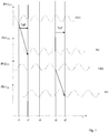
- FIG. 1 shows an illustration of the phase angles and times in an execution of steps a to d with two stationary objects O1 and O2.
- the phase position Ph1 O1 of the oscillation of a first oscillator OZ1 on the first object O1 and the phase position Ph1 O2 of the signal received by a second antenna A2 of the first oscillator OZ1 on the second object O2 and the phase position Ph2 O2 of the oscillations of a second one are shown Oscillator OZ2 at the second object O2 and the phase position Ph2 O1 of the signal received by a first antenna A1 of the second oscillator OZ2 at the first object O1.
- the transmission is indicated by a respective oblique arrow, the time of flight ToF of the signals is in each case marked with a vertical arrow t0, t1, t1 ', t2, t2' represent points in time.
- the oscillators At time t0, the oscillators have a phase offset of dPht0. Due to different frequencies F1, F2 of the oscillators, the phase difference changes over time.
- a measured value matrix with complex measurement numbers can be created.
- a measured value object can be created.
- reference objects the distance and speed between the objects can be determined.
- cPhSum.A is cPhSum of the first execution and cPhSum.B cPhSum of the second execution.
Landscapes
- Engineering & Computer Science (AREA)
- Radar, Positioning & Navigation (AREA)
- Remote Sensing (AREA)
- Physics & Mathematics (AREA)
- General Physics & Mathematics (AREA)
- Computer Networks & Wireless Communication (AREA)
- Radar Systems Or Details Thereof (AREA)
Priority Applications (3)
| Application Number | Priority Date | Filing Date | Title |
|---|---|---|---|
| EP19166622.1A EP3564707B1 (fr) | 2018-05-04 | 2019-04-01 | Procédé et système de mesure de distance et de vitesse à haute résolution |
| US16/391,487 US11175396B2 (en) | 2018-05-04 | 2019-04-23 | Method and system for high resolution range and speedometers |
| CN201910373188.7A CN110440849B (zh) | 2018-05-04 | 2019-05-06 | 用于高分辨率的距离和速度测量的方法和系统 |
Applications Claiming Priority (1)
| Application Number | Priority Date | Filing Date | Title |
|---|---|---|---|
| EP18170949 | 2018-05-04 |
Publications (1)
| Publication Number | Publication Date |
|---|---|
| EP3564706A1 true EP3564706A1 (fr) | 2019-11-06 |
Family
ID=62165373
Family Applications (1)
| Application Number | Title | Priority Date | Filing Date |
|---|---|---|---|
| EP18171965.9A Withdrawn EP3564706A1 (fr) | 2018-05-04 | 2018-05-12 | Procédé et système de mesure de distance et de vitesse à haute résolution |
Country Status (3)
| Country | Link |
|---|---|
| US (1) | US11175396B2 (fr) |
| EP (1) | EP3564706A1 (fr) |
| CN (1) | CN110440849B (fr) |
Cited By (1)
| Publication number | Priority date | Publication date | Assignee | Title |
|---|---|---|---|---|
| WO2022096510A1 (fr) * | 2020-11-04 | 2022-05-12 | Lambda:4 Entwicklungen Gmbh | Procédé de télémétrie par radio |
Citations (3)
| Publication number | Priority date | Publication date | Assignee | Title |
|---|---|---|---|---|
| WO2003081516A1 (fr) * | 2002-03-21 | 2003-10-02 | Siemens Aktiengesellschaft | Systeme d'identification conçu pour detecter une autorisation d'acces a un objet ou d'utilisation d'un objet, en particulier d'un vehicule automobile |
| EP2196823A1 (fr) | 2008-12-12 | 2010-06-16 | Lambda: 4 Entwicklungen GmbH | Procédé de détermination de la distance entre deux objets |
| DE102009060592A1 (de) * | 2008-12-30 | 2010-07-08 | Atmel Automotive Gmbh | Schaltung und Verfahren zur Entfernungsmessung zwischen zwei Knoten eines Funknetzes |
Family Cites Families (9)
| Publication number | Priority date | Publication date | Assignee | Title |
|---|---|---|---|---|
| US20030165863A1 (en) * | 2001-01-16 | 2003-09-04 | Millennium Pharmaceuticals, Inc. | NARC10 and NARC16, programmed cell death-associated molecules and uses thereof |
| DE10155251A1 (de) * | 2001-11-09 | 2003-06-18 | Siemens Ag | Transpondersystem und Verfahren zur Entfernungsmessung |
| DE102006004023A1 (de) * | 2006-01-27 | 2007-08-09 | Siemens Ag | Vorrichtung und Verfahren zur mehrdimensionalen Ortung von Zielobjekten, insbesondere RFID-Transpondern |
| JP5407856B2 (ja) * | 2007-02-22 | 2014-02-05 | 日本電気株式会社 | マルチバンドトランシーバおよび該トランシーバを用いた測位システム |
| EP2204669A1 (fr) * | 2008-12-30 | 2010-07-07 | Atmel Automotive GmbH | Système, procédé et commutation destinés à mesurer l'éloignement entre deux noeuds d'un réseau radio |
| CN103154767B (zh) * | 2010-10-26 | 2015-04-01 | 阿尔卑斯电气株式会社 | 距离测量装置 |
| DE102013008607A1 (de) * | 2013-05-22 | 2014-11-27 | S.M.S Smart Microwave Sensors Gmbh | Verfahren zur Bestimmung von Abstand und Relativgeschwindigkeit eines entfernten Objekts |
| DE102014010990B4 (de) * | 2014-07-29 | 2021-06-17 | Jenoptik Robot Gmbh | Verfahren und Vorrichtung zum Erkennen von einer Geschwindigkeit und einer Entfernung zumindest eines Objekts in Bezug zu einem Empfänger eines Empfangssignals |
| DE102015107419A1 (de) * | 2015-05-12 | 2016-11-17 | HÜBNER GmbH & Co. KG | Radarvorrichtung |
-
2018
- 2018-05-12 EP EP18171965.9A patent/EP3564706A1/fr not_active Withdrawn
-
2019
- 2019-04-23 US US16/391,487 patent/US11175396B2/en active Active
- 2019-05-06 CN CN201910373188.7A patent/CN110440849B/zh active Active
Patent Citations (3)
| Publication number | Priority date | Publication date | Assignee | Title |
|---|---|---|---|---|
| WO2003081516A1 (fr) * | 2002-03-21 | 2003-10-02 | Siemens Aktiengesellschaft | Systeme d'identification conçu pour detecter une autorisation d'acces a un objet ou d'utilisation d'un objet, en particulier d'un vehicule automobile |
| EP2196823A1 (fr) | 2008-12-12 | 2010-06-16 | Lambda: 4 Entwicklungen GmbH | Procédé de détermination de la distance entre deux objets |
| DE102009060592A1 (de) * | 2008-12-30 | 2010-07-08 | Atmel Automotive Gmbh | Schaltung und Verfahren zur Entfernungsmessung zwischen zwei Knoten eines Funknetzes |
Cited By (1)
| Publication number | Priority date | Publication date | Assignee | Title |
|---|---|---|---|---|
| WO2022096510A1 (fr) * | 2020-11-04 | 2022-05-12 | Lambda:4 Entwicklungen Gmbh | Procédé de télémétrie par radio |
Also Published As
| Publication number | Publication date |
|---|---|
| CN110440849A (zh) | 2019-11-12 |
| CN110440849B (zh) | 2023-05-12 |
| US11175396B2 (en) | 2021-11-16 |
| US20190339377A1 (en) | 2019-11-07 |
Similar Documents
| Publication | Publication Date | Title |
|---|---|---|
| EP3123199B1 (fr) | Procédé mis en oeuvre dans un système de radar, système de radar et dispositif d'un système de radar | |
| EP3564707B1 (fr) | Procédé et système de mesure de distance et de vitesse à haute résolution | |
| DE112005003673B4 (de) | Zielerfassungsverfahren und Zielerfassungsvorrichtung | |
| DE102016117254A1 (de) | Radarvorrichtung, Signalverarbeitungsvorrichtung für Radarvorrichtung und Geschwindigkeitsmessverfahren für Radarvorrichtung | |
| DE102014114350A1 (de) | Radarvorrichtung | |
| DE2410500A1 (de) | Radarsystem mit hohem entfernungsaufloesungsvermoegen | |
| DE102016118431A1 (de) | Signalverarbeitungsvorrichtung einer Radarvorrichtung und Signalverarbeitungsverfahren für eine Radarvorrichtung | |
| DE102009050796B4 (de) | Verfahren und Anordnung zur Messung der Signallaufzeit zwischen einem Sender und einem Empfänger | |
| EP3752858B1 (fr) | Capteur radar à large bande à résolution angulaire pour véhicules automobiles | |
| DE102007008587A1 (de) | Elektronische Abtastradarvorrichtung | |
| EP3803454A1 (fr) | Procédé radar à ouverture synthetique et dispositif radar à ouverture synthetique | |
| DE2348458A1 (de) | Impulsradarsystem | |
| DE102007054298A1 (de) | Radarvorrichtung | |
| DE112019006256T5 (de) | Radarvorrichtung | |
| DE102009037628A1 (de) | Positionierungssystem | |
| WO2020011413A1 (fr) | Procédé de localisation pour la localisation d'au moins un objet au moyen de signaux à base d'ondes et système de localisation | |
| DE2941525C2 (fr) | ||
| DE112020001327T5 (de) | Radar-Vorrichtung | |
| DE102008011889A1 (de) | Digitale Strahlformung mit frequenzmodulierten Signalen | |
| EP3564706A1 (fr) | Procédé et système de mesure de distance et de vitesse à haute résolution | |
| DE112013006929T5 (de) | Gemeinsame-Koordinaten-Quarz-Schleife zum Reduzieren des Einflusses von Stoß und Vibration auf Globalnavigationssatellitensystemmessungen | |
| DE112018007553T5 (de) | Radareinrichtung, radareinrichtungssteuerschaltung und radareinrichtungsspeichermedium | |
| DE102020008040A1 (de) | Radarempfangssystem und verfahren zur kompensation eines phasenfehlers zwischen radarempfangsschaltungen | |
| DE112021001114T5 (de) | Radarvorrichtung, fahrzeug und verfahren zum schätzen einer anzahl von ankommenden wellen | |
| WO2022096509A1 (fr) | Procédé de détermination d'une distance selon un procédé à haute résolution basé sur des mesures de temps de propagation de signaux |
Legal Events
| Date | Code | Title | Description |
|---|---|---|---|
| PUAI | Public reference made under article 153(3) epc to a published international application that has entered the european phase |
Free format text: ORIGINAL CODE: 0009012 |
|
| AK | Designated contracting states |
Kind code of ref document: A1 Designated state(s): AL AT BE BG CH CY CZ DE DK EE ES FI FR GB GR HR HU IE IS IT LI LT LU LV MC MK MT NL NO PL PT RO RS SE SI SK SM TR |
|
| AX | Request for extension of the european patent |
Extension state: BA ME |
|
| STAA | Information on the status of an ep patent application or granted ep patent |
Free format text: STATUS: THE APPLICATION IS DEEMED TO BE WITHDRAWN |
|
| 18D | Application deemed to be withdrawn |
Effective date: 20200603 |