EP3564075B1 - Stossfänger mit integrierter markierungszelle - Google Patents
Stossfänger mit integrierter markierungszelle Download PDFInfo
- Publication number
- EP3564075B1 EP3564075B1 EP19170357.8A EP19170357A EP3564075B1 EP 3564075 B1 EP3564075 B1 EP 3564075B1 EP 19170357 A EP19170357 A EP 19170357A EP 3564075 B1 EP3564075 B1 EP 3564075B1
- Authority
- EP
- European Patent Office
- Prior art keywords
- bumper
- cell
- vehicle
- cells
- elastic part
- Prior art date
- Legal status (The legal status is an assumption and is not a legal conclusion. Google has not performed a legal analysis and makes no representation as to the accuracy of the status listed.)
- Active
Links
Images



Classifications
-
- B—PERFORMING OPERATIONS; TRANSPORTING
- B62—LAND VEHICLES FOR TRAVELLING OTHERWISE THAN ON RAILS
- B62D—MOTOR VEHICLES; TRAILERS
- B62D41/00—Fittings for identifying vehicles in case of collision; Fittings for marking or recording collision areas
-
- B—PERFORMING OPERATIONS; TRANSPORTING
- B60—VEHICLES IN GENERAL
- B60R—VEHICLES, VEHICLE FITTINGS, OR VEHICLE PARTS, NOT OTHERWISE PROVIDED FOR
- B60R19/00—Wheel guards; Radiator guards, e.g. grilles; Obstruction removers; Fittings damping bouncing force in collisions
- B60R19/02—Bumpers, i.e. impact receiving or absorbing members for protecting vehicles or fending off blows from other vehicles or objects
- B60R19/48—Bumpers, i.e. impact receiving or absorbing members for protecting vehicles or fending off blows from other vehicles or objects combined with, or convertible into, other devices or objects, e.g. bumpers combined with road brushes, bumpers convertible into beds
-
- B—PERFORMING OPERATIONS; TRANSPORTING
- B60—VEHICLES IN GENERAL
- B60R—VEHICLES, VEHICLE FITTINGS, OR VEHICLE PARTS, NOT OTHERWISE PROVIDED FOR
- B60R19/00—Wheel guards; Radiator guards, e.g. grilles; Obstruction removers; Fittings damping bouncing force in collisions
- B60R19/02—Bumpers, i.e. impact receiving or absorbing members for protecting vehicles or fending off blows from other vehicles or objects
- B60R19/18—Bumpers, i.e. impact receiving or absorbing members for protecting vehicles or fending off blows from other vehicles or objects characterised by the cross-section; Means within the bumper to absorb impact
- B60R19/20—Bumpers, i.e. impact receiving or absorbing members for protecting vehicles or fending off blows from other vehicles or objects characterised by the cross-section; Means within the bumper to absorb impact containing mainly gas or liquid, e.g. inflatable
-
- B—PERFORMING OPERATIONS; TRANSPORTING
- B60—VEHICLES IN GENERAL
- B60R—VEHICLES, VEHICLE FITTINGS, OR VEHICLE PARTS, NOT OTHERWISE PROVIDED FOR
- B60R19/00—Wheel guards; Radiator guards, e.g. grilles; Obstruction removers; Fittings damping bouncing force in collisions
- B60R19/02—Bumpers, i.e. impact receiving or absorbing members for protecting vehicles or fending off blows from other vehicles or objects
- B60R19/18—Bumpers, i.e. impact receiving or absorbing members for protecting vehicles or fending off blows from other vehicles or objects characterised by the cross-section; Means within the bumper to absorb impact
- B60R2019/186—Additional energy absorbing means supported on bumber beams, e.g. cellular structures or material
- B60R2019/1866—Cellular structures
Definitions
- the present invention relates to the field of bumpers and more particularly to vehicle bumpers.
- the present invention is more particularly concerned with bumpers incorporating a system making it possible to reveal an impact of the vehicle on any surface.
- Collisions can occur between a vehicle of the ground support equipment type (GSE - Ground Service Equipment) and an aircraft.
- GSE Ground Service Equipment
- certain aircraft may have areas for which such an impact has an impact on the structure, such as for example that of the fuselage, without this being able to be detected with the naked eye.
- the object of the present invention is to provide a vehicle bumper provided with a marking system in the event of a collision allowing easy and rapid replacement of the system in the event of activation of the marking.
- the document US 2013/0197717 A1 discloses a vehicle bumper covered with a rubber coating and having a marking fluid cell.
- the present invention provides a vehicle bumper having the characteristics of claim 1.
- the bumper has at least one of the following optional features, taken alone or in combination.
- the closure means are in the form of two elastic lips superimposed on one another and blocked in a constrained position in abutment against one another, a pressure applied to the bumper at the level of the lips of a determined minimum intensity ensuring the release allowing the lips to regain a natural position in which the opening of the cell to the outside is released.
- the closure means are in the form of an attached breakable link ensuring the closure of the cell, a pressure applied to the link of a determined minimum intensity leading to its rupture and the release of the opening of the cell towards outside.
- the cells are distributed transversely over at least part of the width of the bumper.
- each cell extends transversely over at least part of the width of the bumper.
- the transversely extending cells are generally cylindrical in shape.
- Cells are positioned at several levels in height.
- the bumper comprises a structural non-elastic part fixed to the elastic part and comprising the means for fixing to said vehicle.
- the present invention also relates to the vehicle provided with a bumper having at least one of the optional characteristics presented above, taken individually or in combination, the elastic part being positioned at least partially in the outer peripheral part.
- the present invention also relates to a method for marking a surface with which a vehicle exhibiting at least one of the optional characteristics presented above, taken individually or in combination, collides and such that, upon impact, the front part of the bumper exerts a pressure on the said cell or cells allowing the flow of the marking fluid through the opening or openings released to the outside.
- the vehicle 2 given by way of illustration in the following description is a vehicle of the ground support equipment type.
- a vehicle may for example be a towing vehicle for moving the aircraft on the ground, a vehicle for transporting a baggage belt, a vehicle for transporting baggage or baggage, freight or passenger containers, airport staff or companies, a tanker truck for supplying the aircraft with water, fuel or other, a catering vehicle for loading and unloading trolleys for example, a drinking water supply vehicle or other , an empty toilet vehicle, a vehicle for transporting the passenger embarkation / disembarkation staircase, etc.
- the present invention may relate to any other type of vehicle.
- transverse is understood in the direction of the width of the vehicle
- longitudinal is understood to mean a direction perpendicular to the transverse direction, namely in the direction of the length of the vehicle.
- the direction perpendicular to the direction both transverse and longitudinal is designated by the expression "in height" and corresponds to the vertical direction.
- front and rear are to be considered in relation to the direction of travel of the vehicle, this direction being represented by an arrow A on the figure 1 .
- the vehicle 2 comprises a bumper 4 having at least one elastic part 6. It also includes a non-elastic part 8 constituting a structural framework which contributes to the rigidity and the transmission of forces and to which the elastic part 6 is fixed by any type of means.
- the non-elastic part 8 will be called the structural part in the following.
- the elastic part 6 is positioned at least partially in the outer peripheral part at the level of the bumper. In other words, the elastic part 6 is positioned longitudinally at least partially at the outer extremal level of the bumper.
- dotted lines symbolize a conventional type screw junction; any other type of fixing can be used.
- the attachment of the elastic part 6 to the structural part 8 is removable.
- the elastic part 6 can be easily separated from the structural part 8 without damaging the latter and removed from the vehicle 2. In this case, it is a junction 10 by screw and it is therefore sufficient to perform a simple unscrewing. to separate the elastic part of the vehicle 2.
- the structural part 8 is itself fixed by any type of means to the body of the vehicle 2 and for example in the same way as for the elastic part 6; dotted lines symbolize a junction 12 by screws of conventional type allowing easy dismantling of the structural part 8 with or without the elastic part 6 depending on whether it has itself been dismantled or not.
- the elastic part 6 of the bumper 4 has the function of damping the frontal impacts by its elastic deformation the time of the stress; if the impact was not too violent, it then returns to its original shape and dimension, having prevented damage to the vehicle.
- the structural part 8 can be metallic and the elastic part 6 can be made of a rubber-like material.
- the bumper 4 has an elastic part 6 but no non-elastic part.
- the elastic part 6 is directly fixed to the body of the vehicle 2.
- the body of the vehicle then constitutes the structural part 8.
- the figures 1 to 3 represent longitudinal sections of the vehicle 2 along a plane XX (shown in the figures 8 and 9 ) vertical central to the vehicle. Throughout the remainder of the description, it is considered that the vehicle 2 rests on horizontal ground and that any direction perpendicular to the ground is vertical. Conventionally, the bumper 4 extends transversely to the front of the vehicle 2 over the majority of the width of the latter or even beyond, presenting curvatures on either side of the vehicle to follow its contours. .
- the elastic part 6 has a hollow convex shape. According to another embodiment, it could be full.
- the elastic part 6 has a curved front portion 14 of convex section. In the form illustrated, it also has a rear portion 16, called the base, planar.
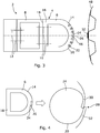
- the elastic part 6 has a D-shaped section; the base 16 forms the bar of the D and is intended to rest against a flat surface 18 of the structural part 8 in order to fix it.
- the front portion 14 of the elastic part 6 incorporates at least one cell 20 of fluid 22 for marking.
- the cell 20 has any type of shape making it possible to offer a cavity 24 for storing the marking fluid.
- the front portion 14 of part 6 elastic has several cells 20 extending transversely across the width of the bumper in the transverse direction. They extend for example over more than 50% of the width of the bumper or even over more than 80% of the width of the bumper (as visible in the example shown on figure 9 ).
- the cells are generally cylindrical in shape with an axis circular section in the transverse direction along the bumper.
- the cells could have any other type of shape and for example an oval or equivalent section or even any other type of shape and for example spherical or other.
- the cells 20 are distributed over a wide area in height parallel to each other as revealed by section AA on the figure 9 . They are concentrated in the front end part of the front portion 14. On the same longitudinal axis, a single cell 20 is provided. Indeed, the cell 20 has an opening towards the outside: also because of this opening towards the outside, it is not possible to provide a set of cells more receding longitudinally, called second level cells, except to provide a connection. with the cells communicating with the outside then called first level cells or a channel allowing the second level cell located in the thickness of the elastic part to communicate with the outside. As the figures 1 to 4 and 8 and 9 , cells 20 are positioned next to each other in the height direction so that a space remains between them.
- the cells 20 extend in the transverse direction for more than half the width of the elastic part and in the illustrated case, over 80% of the width of the elastic part.
- the transverse ends of the cell 20 are located only on the central branch of the elastic part.
- the cells can extend into the side branches; the transverse ends of the cell are then located on the side branches
- At least part of the cells 20 or even all of them as in the example illustrated have a direct opening 26 to the outside.
- the term "direct” means that the interior of the cell is placed in communication with the exterior by a simple opening 26 in the envelope of the cell.
- the cells 20 are therefore neither completely integrated inside the elastic part which would require a very large impact to allow the fluid to be released from the cells nor completely outside the latter which would place them in direct contact with the cell. external environment and expose them to any type of aggression (friction, inadvertent blow ...) for which it is not for example desired that the fluid is discharged.
- the opening 26 of the cell 20 to the outside is direct.
- the opening 26 is closed by closing means 28 capable, under the effect of a pressure applied on said means, to release the opening offering the marking fluid access to the outside of the cell through which it can to flow.
- the closure means 28 are integrated into the elastic part 6.
- the cell 20 being open towards the outside, two lips 30, 32 are formed respectively on either side of the opening 26, an upper lip 30 and a lower lip 32.
- the lips 30, 32 are distant from each other to form said opening 26 towards the outside.
- the lips 30, 32 have respectively for one a curvature 34 bending the relevant lip towards the inside of the cell and for the other a curvature 36 bending the relevant lip towards the outside.
- the lower and upper lips 32 and 30 are superimposed at a distance from one another. In the example illustrated, the lower lip 32 is curved inward and the upper lip 30 is curved outward.
- the outward curvature lip 30 is placed inside the inward curvature lip 32 as shown by Fig. figure 4 .
- the lips 30, 32 are then in contact; the lips seeking to resume their natural position, they are pressed against each other, abutting against one another.
- the inwardly bent lip 30 seeks to move outward and the outwardly bent lip 32 seeks to move inward.
- the lips are forced into the closed position blocked by one another, thus closing the opening 26 and the cavity 24.
- the closure means 28 are not an integral part of the elastic part and comprise a link 38 in any type of form, strip, patch or other binding the ends of the cell at the level of the opening 26.
- the link 38 is made of a different material which does not need to be elastic and which is therefore chosen appropriately to be breakable. When a pressure of determined minimum intensity is applied to the elastic part at the level of the link 38, it breaks and releases the opening 26.
- closure means 28 Any other embodiment of the closure means 28 is possible, for example of the retractable, folding, etc. type.
- the marking fluid 22 consists of any type of fluid making it possible to leave a mark on the surface of which it is poured.
- Cell 20 has a shape and fluid viscosity such that fluid 22 is at least partially discharged from the cell when opening 26 is released. As shown in the figure 3 , a residue 46 may remain in the bottom of the cell.
- the fluid 22 may be contained in beads 40 housed inside the cell 20. Whatever the embodiment of the cells, the beads rupture under said determined pressure.
- the marking fluid 22 is preferably washable so that it can be subsequently removed from the surface onto which it is poured, once the impact has been detected, visualized and treated. The impacted vehicle can thus, if the collision has not caused any damage, be immediately put back into service.
- the marking fluid 22 may consist, for example, of a washable paint of viscosity chosen according to the various parameters listed above. However, any other type of fluid could be suitable, such as washable ink for example.
- the marking fluid 22 may exhibit luminescence properties making it possible to reveal the impact in the dark.
- the means 28 for closing the cells 20 free the opening 26.
- the lips 30, 32 are pushed towards the interior of the cell, moving them away from one another: the lips 30, 32 no longer being in abutment against each other, they thus free the opening 26 and the marking fluid 22 drain through the opening 26 to spread over the surface against which the vehicle has collided.
- the marking fluid 22 has properties such that it leaves a visible trace 50 on the surface in question.
- the surface is marked and the impact is thus visible to the eye.
- the impacted area is demarcated and it can be checked very quickly if the surface has been damaged.
- the fluid can then be withdrawn from the surface to allow its treatment or to put the aircraft back into service in the example illustrated immediately in the event that there is no damage observed.
- the structure of the fuselage can be damaged and deformed locally: it is necessary to carry out a repair locally and the affected area is located quickly.
- the bumper Because of having emptied at least part of the cells with the impact, the bumper is easily restored by replacing the elastic part. In the example illustrated, it suffices to separate the elastic part 6 from the structural part 8 by unscrewing it and replace it with a new elastic part 6 ready for use. Thus, the repair of the bumper is quick and easy.
Landscapes
- Engineering & Computer Science (AREA)
- Mechanical Engineering (AREA)
- Chemical & Material Sciences (AREA)
- Combustion & Propulsion (AREA)
- Transportation (AREA)
- Refuge Islands, Traffic Blockers, Or Guard Fence (AREA)
- Vibration Dampers (AREA)
- Body Structure For Vehicles (AREA)
- Measuring Fluid Pressure (AREA)
Claims (10)
- Stoßfänger (4) eines Fahrzeugs (2), der mindestens einen Teil (6) aus elastischem Material aufweist, der einen frontalen Bereich (14) darstellt, der mindestens eine Zelle (20) mit Markierungsflüssigkeit (22) beinhaltet, die im Inneren des Teils (6) aus elastischem Material vorgesehen ist,
wobei die mindestens eine Zelle (20) mit Markierungsflüssigkeit (22) eine direkte Öffnung (26) nach außen aufweist, die durch Mittel zum Schließen (28) geschlossen ist, die dazu geeignet sind, unter Einwirkung eines ausgeübten Drucks die Öffnung (26) freizugeben, die der Markierungsflüssigkeit einen Zugang zum Bereich außerhalb der Zelle ermöglicht und durch die sie fließen kann, und in der Art, dass er darüber hinaus Mittel zum Befestigen (12) aufweist, die zur Befestigung an dem Fahrzeug (2) dienen. - Stoßfänger nach Anspruch 1, dadurch gekennzeichnet, dass die Mittel zum Schließen (28) in Form von zwei übereinanderliegenden elastischen Lippen (30, 32) vorliegen, die in der zwangsmäßigen Position, wobei die eine an der anderen anliegt, gesperrt sind, wobei ein auf den Stoßfänger in Höhe der Lippen mit einer bestimmten Mindestintensität ausgeübter Druck das Entsperren sicherstellt und es damit den Lippen ermöglicht, eine natürliche Position wiederzufinden, in der die Öffnung (26) der Zelle nach außen freigegeben ist.
- Stoßfänger nach Anspruch 1, dadurch gekennzeichnet, dass die Mittel zum Schließen (28) in Form einer aufgebrachten trennbaren Verbindung vorliegen, die das Schließen der Zelle (20) sicherstellt, wobei ein auf die Verbindung mit einer bestimmten Mindestintensität ausgeübter Druck zu ihrer Trennung führt und damit zur Freigabe der Öffnung (26) der Zelle nach außen.
- Stoßfänger nach einem der Ansprüche 1 bis 3, dadurch gekennzeichnet, dass die Zellen quer über mindestens einen Teil der Breite des Stoßfängers verteilt sind.
- Stoßfänger nach einem der Ansprüche 1 bis 4, dadurch gekennzeichnet, dass sich für mindestens einen Teil der Zellen (20) jede Zelle quer über mindestens einen Teil der Breite des Stoßfängers erstreckt.
- Stoßfänger nach Anspruch 5, dadurch gekennzeichnet, dass die sich quer erstreckenden Zellen insgesamt eine zylindrische Form haben.
- Stoßfänger nach einem der Ansprüche 1 bis 6, dadurch gekennzeichnet, dass die Zellen (20) auf mehreren Höhenebenen positioniert sind.
- Stoßfänger nach einem der Ansprüche 1 bis 7, dadurch gekennzeichnet, dass der Stoßfänger einen nicht elastischen strukturellen Teil (8) aufweist, der an dem elastischen Teil (6) befestigt ist und die Mittel zum Befestigen (12) an dem Fahrzeug aufweist.
- Fahrzeug, versehen mit einem Stoßfänger nach einem der Ansprüche 1 bis 8, wobei der elastische Teil (6) zumindest teilweise im äußeren Umfangsteil positioniert ist.
- Verfahren zum Markieren einer Oberfläche, mit der ein Fahrzeug (2) nach Anspruch 9 kollidiert, dadurch gekennzeichnet, dass während des Aufpralls der vordere Teil des Stoßfängers (4) Druck auf die Zelle oder die Zellen (20) ausübt und damit das Fließen der Markierungsflüssigkeit (22) durch die nach außen freigegebene(n) Öffnung(en) (26) ermöglicht.
Applications Claiming Priority (1)
| Application Number | Priority Date | Filing Date | Title |
|---|---|---|---|
| FR1853847A FR3080811B1 (fr) | 2018-05-04 | 2018-05-04 | Pare-chocs a cellule de marquage integree |
Publications (2)
| Publication Number | Publication Date |
|---|---|
| EP3564075A1 EP3564075A1 (de) | 2019-11-06 |
| EP3564075B1 true EP3564075B1 (de) | 2020-08-12 |
Family
ID=62597777
Family Applications (1)
| Application Number | Title | Priority Date | Filing Date |
|---|---|---|---|
| EP19170357.8A Active EP3564075B1 (de) | 2018-05-04 | 2019-04-19 | Stossfänger mit integrierter markierungszelle |
Country Status (4)
| Country | Link |
|---|---|
| US (1) | US11577795B2 (de) |
| EP (1) | EP3564075B1 (de) |
| CN (1) | CN110435580A (de) |
| FR (1) | FR3080811B1 (de) |
Families Citing this family (2)
| Publication number | Priority date | Publication date | Assignee | Title |
|---|---|---|---|---|
| CN113470443B (zh) * | 2021-07-03 | 2023-02-28 | 中国飞机强度研究所 | 一种机场地面设备防碰撞预警控制装置 |
| DE102025115402A1 (de) * | 2025-04-22 | 2025-11-13 | Mercedes-Benz Group AG | Schadenswarnvorrichtung |
Family Cites Families (7)
| Publication number | Priority date | Publication date | Assignee | Title |
|---|---|---|---|---|
| US2646016A (en) * | 1951-05-24 | 1953-07-21 | Wilson Loyal Vern | Vehicle collision indicator |
| US3490409A (en) * | 1967-05-11 | 1970-01-20 | Robert L Pomeroy | Traffic accident marker |
| DE2935786A1 (de) * | 1979-09-05 | 1981-04-02 | Josef 8403 Bad Abbach Meier | Vorrichtung zur feststellung von unfallfluechtigen |
| JPH0280467A (ja) * | 1988-09-16 | 1990-03-20 | Chieo Matsuura | 自動車及び自転車等接触衝突発見、連鎖状塗料カプセル |
| KR20000062143A (ko) * | 1999-03-04 | 2000-10-25 | 한상관 | 차량의 사고 표시장치 |
| US8843246B2 (en) * | 2012-01-30 | 2014-09-23 | Meggitt Training Systems Canada Inc. | Crush zones for unmanned vehicles and methods of using the same |
| KR20150097013A (ko) * | 2014-02-17 | 2015-08-26 | 자동차부품연구원 | 액티브 후드 시스템이 구비되는 뺑소니 사고 표시장치 |
-
2018
- 2018-05-04 FR FR1853847A patent/FR3080811B1/fr not_active Expired - Fee Related
-
2019
- 2019-04-19 EP EP19170357.8A patent/EP3564075B1/de active Active
- 2019-05-01 US US16/400,438 patent/US11577795B2/en active Active
- 2019-05-06 CN CN201910370211.7A patent/CN110435580A/zh active Pending
Non-Patent Citations (1)
| Title |
|---|
| None * |
Also Published As
| Publication number | Publication date |
|---|---|
| EP3564075A1 (de) | 2019-11-06 |
| US11577795B2 (en) | 2023-02-14 |
| FR3080811B1 (fr) | 2020-04-10 |
| US20190337578A1 (en) | 2019-11-07 |
| FR3080811A1 (fr) | 2019-11-08 |
| CN110435580A (zh) | 2019-11-12 |
Similar Documents
| Publication | Publication Date | Title |
|---|---|---|
| EP3564075B1 (de) | Stossfänger mit integrierter markierungszelle | |
| EP3530508A1 (de) | Signalisierungseinheit für flügel, entsprechende tür und entsprechendes transportfahrzeug | |
| FR3031080A1 (fr) | Toit de case de train d'atterrissage presentant une conception amelioree | |
| WO2015107274A1 (fr) | Chape de liaison fusible entre le bras de suspension et le berceau moteur | |
| EP2825395B1 (de) | Struktur zur montage einer klammer für eine schreibvorrichtung | |
| EP3564076B1 (de) | Stossfänger mit einer nach aussen offenen eine markierungszelle enthaltenen aussparung | |
| FR2929261A1 (fr) | Structure de guidage pour bouchons. | |
| FR3063699A1 (fr) | Agencement de maintien d'un bac de coffre a l'avant d'une structure de caisse d'un vehicule automobile. | |
| FR2983141A1 (fr) | Ensemble d'un projecteur et son dispositif de montage limitant les reparations de l'aile adjacente lors d'un choc et vehicule correspondant | |
| EP4263295B1 (de) | Stossfängervorrichtung mit integriertem absorber und fahrzeug mit dieser vorrichtung | |
| EP3317164B1 (de) | Kraftfahrzeug mit einem kotflügel mit einer rinne | |
| FR3075711A1 (fr) | Becquet pour vehicule automobile comportant un element optique | |
| FR2952873A1 (fr) | Dispositif de protection des plaques d'immatriculation. | |
| EP3808609B1 (de) | Sensorhalterung für ein fahrzeug | |
| EP3069936B1 (de) | Vorrichtung, die eine trittstufe eines kraftfahrzeugs bildet | |
| FR2944240A1 (fr) | Partie arriere d'un vehicule equipe d'un volet inferieur apte a absorber un choc | |
| EP3868611B1 (de) | Verstärkte heckstruktur eines kraftfahrzeugs | |
| EP3453953B1 (de) | Optischer block mit peripheren öffnungen zum ableiten von verschmutzenden externen elementen | |
| EP1844985B1 (de) | Halte- und Drehgelenkvorrichtung für Kraftfahrzeugheckplatte | |
| EP2108570B1 (de) | Frontteil eines Fahrzeugs, das mit einer Halterung für einen abgeschrägten Kühlergrill ausgestattet ist | |
| FR3079201A1 (fr) | Piece moulee pour la protection de cables d’un frein a main d’un vehicule en presence d’une jambe de calage d’un siege d’enfant | |
| FR3116491A1 (fr) | Dispositif absorbeur d’énergie. | |
| FR3101039A3 (fr) | Pare-chocs ameliore pour vehicule lourd | |
| CA2717215A1 (fr) | Reservoir protege contre la surpression | |
| FR2995276A1 (fr) | Piece de renfort pour anneau de remorquage destine a etre agence a l'arriere d'un chassis d'un vehicule automobile et chassis de vehicule automobile associe |
Legal Events
| Date | Code | Title | Description |
|---|---|---|---|
| STAA | Information on the status of an ep patent application or granted ep patent |
Free format text: STATUS: EXAMINATION IS IN PROGRESS |
|
| PUAI | Public reference made under article 153(3) epc to a published international application that has entered the european phase |
Free format text: ORIGINAL CODE: 0009012 |
|
| 17P | Request for examination filed |
Effective date: 20190423 |
|
| AK | Designated contracting states |
Kind code of ref document: A1 Designated state(s): AL AT BE BG CH CY CZ DE DK EE ES FI FR GB GR HR HU IE IS IT LI LT LU LV MC MK MT NL NO PL PT RO RS SE SI SK SM TR |
|
| AX | Request for extension of the european patent |
Extension state: BA ME |
|
| GRAP | Despatch of communication of intention to grant a patent |
Free format text: ORIGINAL CODE: EPIDOSNIGR1 |
|
| STAA | Information on the status of an ep patent application or granted ep patent |
Free format text: STATUS: GRANT OF PATENT IS INTENDED |
|
| INTG | Intention to grant announced |
Effective date: 20200424 |
|
| RBV | Designated contracting states (corrected) |
Designated state(s): AL AT BE BG CH CY CZ DE DK EE ES FI FR GB GR HR HU IE IS IT LI LT LU LV MC MK MT NL NO PL PT RO RS SE SI SK SM TR |
|
| GRAS | Grant fee paid |
Free format text: ORIGINAL CODE: EPIDOSNIGR3 |
|
| GRAA | (expected) grant |
Free format text: ORIGINAL CODE: 0009210 |
|
| STAA | Information on the status of an ep patent application or granted ep patent |
Free format text: STATUS: THE PATENT HAS BEEN GRANTED |
|
| AK | Designated contracting states |
Kind code of ref document: B1 Designated state(s): AL AT BE BG CH CY CZ DE DK EE ES FI FR GB GR HR HU IE IS IT LI LT LU LV MC MK MT NL NO PL PT RO RS SE SI SK SM TR |
|
| REG | Reference to a national code |
Ref country code: CH Ref legal event code: EP |
|
| REG | Reference to a national code |
Ref country code: DE Ref legal event code: R096 Ref document number: 602019000455 Country of ref document: DE |
|
| REG | Reference to a national code |
Ref country code: IE Ref legal event code: FG4D Free format text: LANGUAGE OF EP DOCUMENT: FRENCH |
|
| REG | Reference to a national code |
Ref country code: AT Ref legal event code: REF Ref document number: 1301253 Country of ref document: AT Kind code of ref document: T Effective date: 20200915 |
|
| REG | Reference to a national code |
Ref country code: LT Ref legal event code: MG4D |
|
| REG | Reference to a national code |
Ref country code: NL Ref legal event code: MP Effective date: 20200812 |
|
| PG25 | Lapsed in a contracting state [announced via postgrant information from national office to epo] |
Ref country code: NO Free format text: LAPSE BECAUSE OF FAILURE TO SUBMIT A TRANSLATION OF THE DESCRIPTION OR TO PAY THE FEE WITHIN THE PRESCRIBED TIME-LIMIT Effective date: 20201112 Ref country code: GR Free format text: LAPSE BECAUSE OF FAILURE TO SUBMIT A TRANSLATION OF THE DESCRIPTION OR TO PAY THE FEE WITHIN THE PRESCRIBED TIME-LIMIT Effective date: 20201113 Ref country code: BG Free format text: LAPSE BECAUSE OF FAILURE TO SUBMIT A TRANSLATION OF THE DESCRIPTION OR TO PAY THE FEE WITHIN THE PRESCRIBED TIME-LIMIT Effective date: 20201112 Ref country code: SE Free format text: LAPSE BECAUSE OF FAILURE TO SUBMIT A TRANSLATION OF THE DESCRIPTION OR TO PAY THE FEE WITHIN THE PRESCRIBED TIME-LIMIT Effective date: 20200812 Ref country code: HR Free format text: LAPSE BECAUSE OF FAILURE TO SUBMIT A TRANSLATION OF THE DESCRIPTION OR TO PAY THE FEE WITHIN THE PRESCRIBED TIME-LIMIT Effective date: 20200812 Ref country code: LT Free format text: LAPSE BECAUSE OF FAILURE TO SUBMIT A TRANSLATION OF THE DESCRIPTION OR TO PAY THE FEE WITHIN THE PRESCRIBED TIME-LIMIT Effective date: 20200812 Ref country code: FI Free format text: LAPSE BECAUSE OF FAILURE TO SUBMIT A TRANSLATION OF THE DESCRIPTION OR TO PAY THE FEE WITHIN THE PRESCRIBED TIME-LIMIT Effective date: 20200812 |
|
| REG | Reference to a national code |
Ref country code: AT Ref legal event code: MK05 Ref document number: 1301253 Country of ref document: AT Kind code of ref document: T Effective date: 20200812 |
|
| PG25 | Lapsed in a contracting state [announced via postgrant information from national office to epo] |
Ref country code: LV Free format text: LAPSE BECAUSE OF FAILURE TO SUBMIT A TRANSLATION OF THE DESCRIPTION OR TO PAY THE FEE WITHIN THE PRESCRIBED TIME-LIMIT Effective date: 20200812 Ref country code: RS Free format text: LAPSE BECAUSE OF FAILURE TO SUBMIT A TRANSLATION OF THE DESCRIPTION OR TO PAY THE FEE WITHIN THE PRESCRIBED TIME-LIMIT Effective date: 20200812 Ref country code: PL Free format text: LAPSE BECAUSE OF FAILURE TO SUBMIT A TRANSLATION OF THE DESCRIPTION OR TO PAY THE FEE WITHIN THE PRESCRIBED TIME-LIMIT Effective date: 20200812 Ref country code: NL Free format text: LAPSE BECAUSE OF FAILURE TO SUBMIT A TRANSLATION OF THE DESCRIPTION OR TO PAY THE FEE WITHIN THE PRESCRIBED TIME-LIMIT Effective date: 20200812 Ref country code: IS Free format text: LAPSE BECAUSE OF FAILURE TO SUBMIT A TRANSLATION OF THE DESCRIPTION OR TO PAY THE FEE WITHIN THE PRESCRIBED TIME-LIMIT Effective date: 20201212 |
|
| PG25 | Lapsed in a contracting state [announced via postgrant information from national office to epo] |
Ref country code: SM Free format text: LAPSE BECAUSE OF FAILURE TO SUBMIT A TRANSLATION OF THE DESCRIPTION OR TO PAY THE FEE WITHIN THE PRESCRIBED TIME-LIMIT Effective date: 20200812 Ref country code: RO Free format text: LAPSE BECAUSE OF FAILURE TO SUBMIT A TRANSLATION OF THE DESCRIPTION OR TO PAY THE FEE WITHIN THE PRESCRIBED TIME-LIMIT Effective date: 20200812 Ref country code: DK Free format text: LAPSE BECAUSE OF FAILURE TO SUBMIT A TRANSLATION OF THE DESCRIPTION OR TO PAY THE FEE WITHIN THE PRESCRIBED TIME-LIMIT Effective date: 20200812 Ref country code: CZ Free format text: LAPSE BECAUSE OF FAILURE TO SUBMIT A TRANSLATION OF THE DESCRIPTION OR TO PAY THE FEE WITHIN THE PRESCRIBED TIME-LIMIT Effective date: 20200812 Ref country code: EE Free format text: LAPSE BECAUSE OF FAILURE TO SUBMIT A TRANSLATION OF THE DESCRIPTION OR TO PAY THE FEE WITHIN THE PRESCRIBED TIME-LIMIT Effective date: 20200812 |
|
| REG | Reference to a national code |
Ref country code: DE Ref legal event code: R097 Ref document number: 602019000455 Country of ref document: DE |
|
| PG25 | Lapsed in a contracting state [announced via postgrant information from national office to epo] |
Ref country code: ES Free format text: LAPSE BECAUSE OF FAILURE TO SUBMIT A TRANSLATION OF THE DESCRIPTION OR TO PAY THE FEE WITHIN THE PRESCRIBED TIME-LIMIT Effective date: 20200812 Ref country code: AT Free format text: LAPSE BECAUSE OF FAILURE TO SUBMIT A TRANSLATION OF THE DESCRIPTION OR TO PAY THE FEE WITHIN THE PRESCRIBED TIME-LIMIT Effective date: 20200812 Ref country code: AL Free format text: LAPSE BECAUSE OF FAILURE TO SUBMIT A TRANSLATION OF THE DESCRIPTION OR TO PAY THE FEE WITHIN THE PRESCRIBED TIME-LIMIT Effective date: 20200812 |
|
| PLBE | No opposition filed within time limit |
Free format text: ORIGINAL CODE: 0009261 |
|
| STAA | Information on the status of an ep patent application or granted ep patent |
Free format text: STATUS: NO OPPOSITION FILED WITHIN TIME LIMIT |
|
| PG25 | Lapsed in a contracting state [announced via postgrant information from national office to epo] |
Ref country code: SK Free format text: LAPSE BECAUSE OF FAILURE TO SUBMIT A TRANSLATION OF THE DESCRIPTION OR TO PAY THE FEE WITHIN THE PRESCRIBED TIME-LIMIT Effective date: 20200812 |
|
| 26N | No opposition filed |
Effective date: 20210514 |
|
| PG25 | Lapsed in a contracting state [announced via postgrant information from national office to epo] |
Ref country code: IT Free format text: LAPSE BECAUSE OF FAILURE TO SUBMIT A TRANSLATION OF THE DESCRIPTION OR TO PAY THE FEE WITHIN THE PRESCRIBED TIME-LIMIT Effective date: 20200812 |
|
| PG25 | Lapsed in a contracting state [announced via postgrant information from national office to epo] |
Ref country code: MC Free format text: LAPSE BECAUSE OF FAILURE TO SUBMIT A TRANSLATION OF THE DESCRIPTION OR TO PAY THE FEE WITHIN THE PRESCRIBED TIME-LIMIT Effective date: 20200812 |
|
| PG25 | Lapsed in a contracting state [announced via postgrant information from national office to epo] |
Ref country code: LU Free format text: LAPSE BECAUSE OF NON-PAYMENT OF DUE FEES Effective date: 20210419 |
|
| REG | Reference to a national code |
Ref country code: BE Ref legal event code: MM Effective date: 20210430 |
|
| PG25 | Lapsed in a contracting state [announced via postgrant information from national office to epo] |
Ref country code: IE Free format text: LAPSE BECAUSE OF NON-PAYMENT OF DUE FEES Effective date: 20210419 |
|
| PG25 | Lapsed in a contracting state [announced via postgrant information from national office to epo] |
Ref country code: IS Free format text: LAPSE BECAUSE OF FAILURE TO SUBMIT A TRANSLATION OF THE DESCRIPTION OR TO PAY THE FEE WITHIN THE PRESCRIBED TIME-LIMIT Effective date: 20201212 |
|
| PG25 | Lapsed in a contracting state [announced via postgrant information from national office to epo] |
Ref country code: BE Free format text: LAPSE BECAUSE OF NON-PAYMENT OF DUE FEES Effective date: 20210430 |
|
| REG | Reference to a national code |
Ref country code: CH Ref legal event code: PL |
|
| PG25 | Lapsed in a contracting state [announced via postgrant information from national office to epo] |
Ref country code: LI Free format text: LAPSE BECAUSE OF NON-PAYMENT OF DUE FEES Effective date: 20220430 Ref country code: CH Free format text: LAPSE BECAUSE OF NON-PAYMENT OF DUE FEES Effective date: 20220430 |
|
| PG25 | Lapsed in a contracting state [announced via postgrant information from national office to epo] |
Ref country code: PT Free format text: LAPSE BECAUSE OF FAILURE TO SUBMIT A TRANSLATION OF THE DESCRIPTION OR TO PAY THE FEE WITHIN THE PRESCRIBED TIME-LIMIT Effective date: 20201214 |
|
| PG25 | Lapsed in a contracting state [announced via postgrant information from national office to epo] |
Ref country code: CY Free format text: LAPSE BECAUSE OF FAILURE TO SUBMIT A TRANSLATION OF THE DESCRIPTION OR TO PAY THE FEE WITHIN THE PRESCRIBED TIME-LIMIT Effective date: 20200812 |
|
| PG25 | Lapsed in a contracting state [announced via postgrant information from national office to epo] |
Ref country code: HU Free format text: LAPSE BECAUSE OF FAILURE TO SUBMIT A TRANSLATION OF THE DESCRIPTION OR TO PAY THE FEE WITHIN THE PRESCRIBED TIME-LIMIT; INVALID AB INITIO Effective date: 20190419 |
|
| PG25 | Lapsed in a contracting state [announced via postgrant information from national office to epo] |
Ref country code: SI Free format text: LAPSE BECAUSE OF FAILURE TO SUBMIT A TRANSLATION OF THE DESCRIPTION OR TO PAY THE FEE WITHIN THE PRESCRIBED TIME-LIMIT Effective date: 20200812 |
|
| PG25 | Lapsed in a contracting state [announced via postgrant information from national office to epo] |
Ref country code: MK Free format text: LAPSE BECAUSE OF FAILURE TO SUBMIT A TRANSLATION OF THE DESCRIPTION OR TO PAY THE FEE WITHIN THE PRESCRIBED TIME-LIMIT Effective date: 20200812 |
|
| PG25 | Lapsed in a contracting state [announced via postgrant information from national office to epo] |
Ref country code: MT Free format text: LAPSE BECAUSE OF FAILURE TO SUBMIT A TRANSLATION OF THE DESCRIPTION OR TO PAY THE FEE WITHIN THE PRESCRIBED TIME-LIMIT Effective date: 20200812 |
|
| PGFP | Annual fee paid to national office [announced via postgrant information from national office to epo] |
Ref country code: DE Payment date: 20250422 Year of fee payment: 7 |
|
| PGFP | Annual fee paid to national office [announced via postgrant information from national office to epo] |
Ref country code: GB Payment date: 20250423 Year of fee payment: 7 |
|
| PGFP | Annual fee paid to national office [announced via postgrant information from national office to epo] |
Ref country code: FR Payment date: 20250425 Year of fee payment: 7 |
|
| PG25 | Lapsed in a contracting state [announced via postgrant information from national office to epo] |
Ref country code: TR Free format text: LAPSE BECAUSE OF FAILURE TO SUBMIT A TRANSLATION OF THE DESCRIPTION OR TO PAY THE FEE WITHIN THE PRESCRIBED TIME-LIMIT Effective date: 20200812 |