EP3564058A1 - Projektionsvorrichtung für einen kraftwagen, insbesondere für einen personenkraftwagen, kraftwagen sowie verfahren zum betreiben einer solchen projektionsvorrichtung - Google Patents
Projektionsvorrichtung für einen kraftwagen, insbesondere für einen personenkraftwagen, kraftwagen sowie verfahren zum betreiben einer solchen projektionsvorrichtung Download PDFInfo
- Publication number
- EP3564058A1 EP3564058A1 EP19169308.4A EP19169308A EP3564058A1 EP 3564058 A1 EP3564058 A1 EP 3564058A1 EP 19169308 A EP19169308 A EP 19169308A EP 3564058 A1 EP3564058 A1 EP 3564058A1
- Authority
- EP
- European Patent Office
- Prior art keywords
- projection
- virtual image
- image
- motor vehicle
- imaging surface
- Prior art date
- Legal status (The legal status is an assumption and is not a legal conclusion. Google has not performed a legal analysis and makes no representation as to the accuracy of the status listed.)
- Granted
Links
Images
Classifications
-
- H—ELECTRICITY
- H04—ELECTRIC COMMUNICATION TECHNIQUE
- H04N—PICTORIAL COMMUNICATION, e.g. TELEVISION
- H04N9/00—Details of colour television systems
- H04N9/12—Picture reproducers
- H04N9/31—Projection devices for colour picture display, e.g. using electronic spatial light modulators [ESLM]
- H04N9/3141—Constructional details thereof
- H04N9/3147—Multi-projection systems
-
- B—PERFORMING OPERATIONS; TRANSPORTING
- B60—VEHICLES IN GENERAL
- B60K—ARRANGEMENT OR MOUNTING OF PROPULSION UNITS OR OF TRANSMISSIONS IN VEHICLES; ARRANGEMENT OR MOUNTING OF PLURAL DIVERSE PRIME-MOVERS IN VEHICLES; AUXILIARY DRIVES FOR VEHICLES; INSTRUMENTATION OR DASHBOARDS FOR VEHICLES; ARRANGEMENTS IN CONNECTION WITH COOLING, AIR INTAKE, GAS EXHAUST OR FUEL SUPPLY OF PROPULSION UNITS IN VEHICLES
- B60K35/00—Instruments specially adapted for vehicles; Arrangement of instruments in or on vehicles
- B60K35/60—Instruments characterised by their location or relative disposition in or on vehicles
-
- H—ELECTRICITY
- H04—ELECTRIC COMMUNICATION TECHNIQUE
- H04N—PICTORIAL COMMUNICATION, e.g. TELEVISION
- H04N9/00—Details of colour television systems
- H04N9/12—Picture reproducers
- H04N9/31—Projection devices for colour picture display, e.g. using electronic spatial light modulators [ESLM]
- H04N9/3179—Video signal processing therefor
-
- H—ELECTRICITY
- H04—ELECTRIC COMMUNICATION TECHNIQUE
- H04N—PICTORIAL COMMUNICATION, e.g. TELEVISION
- H04N9/00—Details of colour television systems
- H04N9/12—Picture reproducers
- H04N9/31—Projection devices for colour picture display, e.g. using electronic spatial light modulators [ESLM]
- H04N9/3191—Testing thereof
- H04N9/3194—Testing thereof including sensor feedback
-
- B—PERFORMING OPERATIONS; TRANSPORTING
- B60—VEHICLES IN GENERAL
- B60K—ARRANGEMENT OR MOUNTING OF PROPULSION UNITS OR OF TRANSMISSIONS IN VEHICLES; ARRANGEMENT OR MOUNTING OF PLURAL DIVERSE PRIME-MOVERS IN VEHICLES; AUXILIARY DRIVES FOR VEHICLES; INSTRUMENTATION OR DASHBOARDS FOR VEHICLES; ARRANGEMENTS IN CONNECTION WITH COOLING, AIR INTAKE, GAS EXHAUST OR FUEL SUPPLY OF PROPULSION UNITS IN VEHICLES
- B60K2360/00—Indexing scheme associated with groups B60K35/00 or B60K37/00 relating to details of instruments or dashboards
- B60K2360/20—Optical features of instruments
- B60K2360/21—Optical features of instruments using cameras
-
- B—PERFORMING OPERATIONS; TRANSPORTING
- B60—VEHICLES IN GENERAL
- B60K—ARRANGEMENT OR MOUNTING OF PROPULSION UNITS OR OF TRANSMISSIONS IN VEHICLES; ARRANGEMENT OR MOUNTING OF PLURAL DIVERSE PRIME-MOVERS IN VEHICLES; AUXILIARY DRIVES FOR VEHICLES; INSTRUMENTATION OR DASHBOARDS FOR VEHICLES; ARRANGEMENTS IN CONNECTION WITH COOLING, AIR INTAKE, GAS EXHAUST OR FUEL SUPPLY OF PROPULSION UNITS IN VEHICLES
- B60K2360/00—Indexing scheme associated with groups B60K35/00 or B60K37/00 relating to details of instruments or dashboards
- B60K2360/20—Optical features of instruments
- B60K2360/33—Illumination features
- B60K2360/334—Projection means
-
- B—PERFORMING OPERATIONS; TRANSPORTING
- B60—VEHICLES IN GENERAL
- B60K—ARRANGEMENT OR MOUNTING OF PROPULSION UNITS OR OF TRANSMISSIONS IN VEHICLES; ARRANGEMENT OR MOUNTING OF PLURAL DIVERSE PRIME-MOVERS IN VEHICLES; AUXILIARY DRIVES FOR VEHICLES; INSTRUMENTATION OR DASHBOARDS FOR VEHICLES; ARRANGEMENTS IN CONNECTION WITH COOLING, AIR INTAKE, GAS EXHAUST OR FUEL SUPPLY OF PROPULSION UNITS IN VEHICLES
- B60K2360/00—Indexing scheme associated with groups B60K35/00 or B60K37/00 relating to details of instruments or dashboards
- B60K2360/77—Instrument locations other than the dashboard
- B60K2360/774—Instrument locations other than the dashboard on or in the centre console
Definitions
- the invention relates to a projection device for a motor vehicle, especially for a passenger car, according to the preamble of claim 1. Furthermore, the invention relates to a motor vehicle with such a projection device and a method for operating such a projection device according to the preamble of claim 12.
- the projection device is used for example as a so-called head-up display (HUD) to visually represent information in the interior of the respective motor vehicle.
- the projection device comprises an arranged in the interior of the respective motor vehicle imaging element, which is usually a windshield of the respective motor vehicle or a partially overlapping with the windshield and arranged separately from the windshield trained combiner.
- the combiner is usually arranged on an instrument panel.
- the imaging element has at least one imaging surface.
- the projection device comprises at least one projection element arranged in the interior for projecting at least one virtual image onto the imaging surface.
- the at least one projection element is designed to project at least one virtual image onto the imaging surface.
- the DE 10 2006 000 777 A1 an access control device to allow a driver or passenger access to a vehicle.
- a gear selector lever for a motor vehicle is to be taken as known.
- a motor vehicle known from the DE 10 2014 002 305 A1 a motor vehicle known.
- Object of the present invention is to provide a projection device, a motor vehicle and a method for operating a projection device, so that information can be displayed visually particularly advantageous in the interior of the motor vehicle.
- a first aspect of the invention relates to a projection device for a motor vehicle, preferably designed as a passenger car.
- the projection device has at least one imaging element arranged in the interior of the motor vehicle, which imaging element has at least one imaging surface.
- the projection device has at least one projection element arranged in the interior for projecting at least one virtual image onto the imaging surface.
- the at least one projection element is designed to project at least one virtual image onto the imaging surface.
- the at least one projection element is designed to generate at least one projected and thus virtual image on the imaging surface.
- the projection element is in particular designed to emit light in order thereby to project the virtual image onto the imaging surface.
- One of the vehicle seats for example, the driver's seat, wherein the other vehicle seat is the passenger seat.
- the invention is based on the finding that the center console can be particularly visually perceived optically by the driver and is often viewed by the driver during a drive, since the driver operates, for example, operating elements arranged on or in the vicinity of the center console.
- the driver can briefly look at the center console and thus at its imaging surface during a drive, without the driver being distracted excessively.
- the invention makes it possible for the driver to be able to communicate information visually by means of the projected and therefore virtual image, without the driver being distracted.
- the virtual image is a projected image or is also referred to as a projected image, since it is projected onto the imaging surface by means of the at least one projection element.
- the virtual image is also called a projection.
- Projections have the advantage that light for generating the respective projection can be directed or guided into areas in order to visualize contents in these areas on the basis of the respective projection and thus to be able to communicate optically, whereby no space is available in these areas for conventional electronic screens Available.
- the light for projecting or generating the virtual image can be directed or guided or deflected as required in order to be able to design a light path along which the light for generating the virtual image is guided as needed.
- an at least almost free installation position of the at least one projection element can be selected.
- the installation position of the at least one projection element can be at least substantially independent of the Imaging surface, in particular of their position in the interior, can be selected.
- the optics include, for example, at least one prism or a plurality of prisms in order, for example, to redirect the light for generating the virtual image, in particular by 90 degrees.
- the optics may be designed to deflect the light by more or less 90 degrees.
- the virtual image can be generated particularly advantageously or in particularly advantageous places.
- the virtual picture comprises, for example, at least one number and / or at least one letter and / or at least one symbol different from a number and from a letter ,
- the projection device has a detection device by means of which at least one object arranged in the interior can be detected.
- the object may be, for example, a person, in particular a limb or a part of a limb of a person staying in the interior, or an object, so that at least one person staying in the interior and / or at least one person is present by means of the detection device arranged in the interior object can be detected.
- the at least one projection element can be operated as a function of the detected object.
- the at least one projection element is designed to emit, that is to provide, the light for generating at least part of the virtual image as a function of the detected object.
- the detection device provides at least one signal characterizing the detected objects, in particular electrical, which is received, for example, by the at least one projection element.
- the signal is received by an electronic computing device.
- the electronic computing device generates at least one, in particular electrical, drive signal, which is connected to the at least one projection element is transmitted and received by the at least one projection element.
- the at least one projection element is driven or operated, so that the at least one projection element can be controlled or operated by means of the drive signal as a function of the detected object.
- the at least one projection element is adapted to emit light in at least one emitting area, thereby to the virtual image on the imaging surface project. If, for example, it is determined or detected by means of the detection device that at least a subregion of the object detected by the detection device is arranged in a first part of the emission region, the at least one projection element omits or suppresses the emission of light in the first part of the emission region.
- the at least one projection element While the at least one projection element omits or inhibits the emission of light in the first part of the emission area, the at least one projection element emits light in a second part of the emission area adjoining the first part, thereby producing a smaller image part, in particular with respect to the virtual image to project the virtual image onto the imaging surface.
- the at least one projection element excludes or omits the partial region of the object or the object arranged in the emission region as a whole, so that no light emitted by the at least one projection element falls on the partial region or on the object as a whole. In other words, this prevents the virtual image or part of the virtual image from being projected onto the object or to the partial area.
- the detection device is designed to determine a position of the object in the interior, so that the at least one projection element is operable in dependence on the determined position of the object.
- the detection device is designed to determine a brightness in the interior and / or a brightness in the environment of the motor vehicle, so that the at least one projection element is operable in dependence on the determined or detected brightness.
- the projection element is operable or operated as a function of at least one state value characterizing a state of the at least one projection element.
- the state value characterizes, for example, an age of the at least one projection element.
- This embodiment is based on the finding that light which can be emitted by means of projection elements, in particular its color, can change with increasing age of the respective projection element. In particular, the color red can age quickly.
- the age of the at least one projection element compensation measures can take place, so that, for example, the virtual image also over a long life of the at least one projection element away always the same, from inside the person in the interior visually perceptible appearance.
- the at least one projection element can be operated as a function of a position of the at least one projection element, in particular in the interior and / or in relation to the imaging surface.
- the position of the at least one projection element can be detected, for example, by means of the detection device and / or is stored in a memory device of the aforementioned electronic computing device.
- the emission area is also referred to as the emission area of the at least one projection element, which is also referred to as a projector.
- the at least one projection element as a function of at least one area value characterizing the emission area, the area value being stored, for example, in the electronic calculation device.
- the range value characterizes, for example, at least one or more spatial dimensions or expansions of the emission area, so that particularly advantageously an orientation or position or position of the detected object in relation to the emission area can be determined. In particular, it can be determined as a function of the range value and as a function of the detected object, in particular as a function of its detected position in the interior, whether the object is located in the transmission range.
- the projection device has at least one second projection element arranged in the interior.
- the at least one projection element is also referred to as the first projection element.
- the following and previous comments on the first projection element are, mutatis mutandis, transferable to the second projection element and vice versa.
- the second projection element can emit or emit light, thereby projecting a second virtual image onto the imaging surface.
- the second projection element is designed to project the second virtual image onto the imaging surface, while the at least one projection element projects the image part of the first virtual image onto the imaging surface by means of the light emitted in the second part of the emission region.
- the second virtual image supplements the image part projected onto the imaging surface by means of the at least one projection element to form a virtual overall image projected onto the imaging surface.
- the first projection element projects the first virtual image, in particular in its entirety, onto the imaging surface. If, however, the abovementioned partial area of the object or the object as a whole is arranged in the first part of the emitting area, while the second emitting area is free of objects, the first projection element emits light in the second part of the emitting area, whereas in the first part no light is emitted. As a result, the first projection element projects the said image part onto the imaging surface.
- the first virtual image is formed, for example, in its entirety by the first image part and by a second image part, so that the first image part and the second image part result in entirety or together or in total the first virtual image.
- the first projection element in the first part of the transmission range does not emit light, a projecting of the second image part caused by the first projection element is prevented on the imaging surface, while the first projection element projects the first image part onto the imaging surface.
- the first projection element projects only the first image part onto the imaging surface from the first virtual image.
- the first image part which is projected onto the image surface by means of the first projection element, is supplemented by the second virtual image to the virtual overall image.
- the second virtual image takes the place of the second image part, which is not projected or projected onto the imaging surface by means of the first projection element.
- the second projection element projects the second image part onto the imaging surface, so that the first image part and the second image part form the first virtual image which can be projected onto the imaging surface by means of the first projection element, if the emission region of the first projection element is free of objects is.
- This allows a particularly advantageous and in particular shadow-free projection of the virtual overall image or of the first virtual image, in particular when there are one or more objects in the emission area of the first projection element.
- the first image part and the second virtual image on the imaging surface are arranged without overlapping each other and connect to each other without gaps.
- the virtual overall picture can be displayed without any gaps, as a result of which the information can be communicated optically advantageously to the driver of the motor vehicle or at least one person staying in the interior of the motor vehicle on the basis of the virtual overall picture.
- a further embodiment is characterized in that the first image part and the second virtual image overlap on the imaging surface in respective overlapping regions.
- the virtual overall image corresponds to the first virtual image which can be projected by means of the first projection element by simultaneously emitting light onto the imaging surface both in the first part and in the second part.
- the second virtual image or at least a part of the second virtual image forms the second image part, which can not be projected onto the imaging surface by means of the first projection element.
- a selector lever for selecting gears and / or gears of a transmission of the motor vehicle is movably held on the center console. By moving the selector lever relative to the center console, for example, the driver of the motor vehicle can select respective gears or gear ratios of the transmission.
- the second projection element is held on the selector lever.
- the second projection element is thus movable with the selector lever.
- the at least one projection element is held on the selector lever, so that the first projection element with the selector lever is movable.
- the respective projection element is operable in dependence on a respective position of the selector lever, in particular relative to the center console.
- the selector lever can be moved relative to the center console into a plurality of positions that differ from one another and are also designated as selector lever positions.
- the respective selector lever position is detected, for example, by means of the aforementioned electronic computing device.
- the respective projection element is operated as a function of the respective, detected selector lever position, so that the respective projection element emits the light as a function of the detected selector lever position and thus provides it.
- unwanted changes of the first virtual image or the virtual overall image can be avoided when the selector lever is moved relative to the center console.
- a second aspect of the invention relates to a motor vehicle, preferably designed as a passenger car, which has at least one projection device according to the invention according to the first aspect of the invention.
- Advantages and advantageous embodiments of the first aspect of the invention are to be regarded as advantages and advantageous embodiments of the second aspect of the invention, and vice versa.
- a third aspect of the invention relates to a method for operating a projection device of a motor vehicle, in particular a projection device according to the invention according to the first aspect of the invention.
- the method at least one virtual image is projected onto an imaging surface of an imaging element arranged in the interior by means of at least one projection element of the motor vehicle arranged in the interior of the motor vehicle.
- a center console of the motor vehicle arranged in the vehicle transverse direction between two vehicle seats is used as the imaging element.
- the invention also includes the combinations of features of the described embodiments.
- the invention also includes further developments of the method according to the invention which have features as they have already been described in connection with the developments of the projection device according to the invention. For this reason, the corresponding developments of the method according to the invention are not described again here.
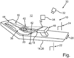
- FIG. 1 Shows a schematic perspective view of a projection device according to the invention for a motor vehicle.
- the exemplary embodiment explained below is a preferred embodiment of the invention.
- the described components of the embodiment each represent individual features of the invention, which are to be considered independently of each other, which also each independently develop the invention and thus also individually or in a different combination than the one shown as part of the invention.
- the described Embodiment also supplemented by further of the already described features of the invention.
- the single FIGURE shows a schematic perspective view of a projection device 10 for a motor vehicle, which is preferably designed as a passenger car.
- the projection device 10 has an imaging element 14 arranged in the interior 12 of the motor vehicle, which imaging element has at least one imaging surface 16.
- the projection device 10 comprises at least one first projection element 18 arranged in the interior 12 for projecting at least one virtual image 20 onto the imaging surface 16.
- the imaging element 14 is in the vehicle transverse direction between two in formed of the vehicle seats 22 and 24 arranged particularly schematically illustrated center console 26 of the motor vehicle.
- the vehicle transverse direction is illustrated by a double arrow 28 in FIG.
- the projection device 10 has at least one detection device 30, by means of which at least one object arranged in the interior 12 can be detected or detected.
- the detection device 30 comprises at least one camera 32, by means of which images of at least a partial region of the interior 12 can be detected.
- the images can be subjected to image processing, for example, by means of an electronic computing device 34 of the detection device 30 or of the projection device 10, which is shown particularly schematically in FIG. If, for example, the aforementioned object is detected on the basis of at least one of the images, then the electronic computing device 34 can store the projection element 18 in FIG Control dependence on the detected object and thus operate, especially control or regulate.
- the projection element 18 is designed to emit light in a particularly three-dimensional emission area 36 in order thereby to project the virtual image 20 onto the imaging area 16 by means of the light emitted in the emission area 36. If, for example, the aforementioned object is detected by means of the detection device 30 and is thereby detected or detected, in particular by means of the computing device 34, that the object or at least one subregion of the detected object is located in a first part of the emission region 36 the projection element 18 emits no light in the first part of the emission area 36, while the projection element 18 emits light in a second part of the emission area 36 adjoining the first part.
- the projection element 18 projects a first image part of the virtual image 20 onto the imaging surface 16 by means of the light emitted or emitted in the second part. If the emission area 36 is free of objects, for example, the projection element 18 transmits both in the first part and in the second Part of the Aussende Siemenss 36 light, thereby projecting the virtual image 20 in its entirety on the imaging surface 16. In this case, for example, the first part and the second part together result in the transmission range 36.
- the projection device 10 comprises at least one second projection element 38 arranged in the interior 12 and also referred to as a second beamer.
- the projection element 38 is configured to emit or emit light in a second emission area 40 and thereby to project a second virtual image 42 onto the emission area 36.
- At least respective parts of the transmission areas 36 and 40 are arranged without overlapping or without covering each other.
- the projection element 18 While now the projection element 18 emits no light in the first part of the emission area 36 and emits light in the second part of the emission area 36, whereby the projection element 18 uses the light emitted in the second part of the emission area 36 to apply the above-mentioned first image part of the first virtual image 20 to the Imaging surface 16 is projected, the projection element 38 projects the second virtual image onto the imaging surface 16, whereby the second virtual image complements the image part projected on the imaging surface 16 by the projection element 18 to form a virtual overall image 44 projected onto the imaging surface 16.
- the projection element 18 can project the virtual image 20 entirely onto the imaging surface 16, so that the projection element 18 projects both the first image part and, for example, a second image part of the first virtual image 20 onto the imaging surface 16 can or projected.
- the first image part and the second image part of the virtual image 20 sum up the virtual image 20 in their entirety.
- the projection element 18 radiates light only in the second part of the emitting area 36 with respect to the parts of the emitting area 36, so that the projection element 18 only with respect to the image parts of the virtual image 20 projected the first image part onto the imaging surface 16.
- the second image part is not projected onto the imaging surface 16 by means of the projection element 18.
- the second virtual image 42 takes the place of the second image part, so that at least the part of the second virtual image 42 supplements the first image part to the virtual image 20.
- the first image part and the second virtual image 42 projected onto the imaging surface 16 by means of the projection element 18 result in the total image 44, which is, for example, larger than the virtual image 20 and the virtual image 42 is considered individually.
- the virtual image 42 can have, for example, at least a third image part and a fourth image part, wherein the third image part and the fourth image part sum up the second virtual image 42.
- the third image part supplements the first image part to the virtual image 20
- the fourth image part supplements the third image part to the virtual image 42.
- the first image part, the third image part and the fourth image part sum up the overall image 44, wherein the virtual image 20 is at least part of the overall image 44, or the virtual image 20 corresponds to the overall image 44.
- the fourth image portion of the virtual image 42 is an image portion not belonging to the virtual image 20 such that the overall virtual image 44 is larger than the single virtual image 20 and larger than the single virtual image 42.
- the first image part and the second virtual image 42 can be arranged on the imaging surface 16 without overlapping one another and thereby join each other gaplessly, or the first image part and the second virtual image 42 overlap on the imaging surface 16 in respective overlap regions 46.
- a selector lever 48 for selecting gears and / or speed ratios of a transmission of the motor vehicle is movably held on the center console 26.
- the selector lever 48 can thus be moved into a plurality of mutually different positions relative to the center console 26.
- both the projection element 18 and the projection element 38 are held on the selector lever 48 and thus with the selector lever 48 with movable.
- the virtual image 20, in particular the first image part to display or indicate at least one symbol characterizing the current position of the selector lever 48 or characterizing the current position of the selector lever 48, so that, for example, based on the virtual image 20 or on the basis of FIG first image part of the currently selected gear or the currently selected gear of the transmission is projected onto the imaging surface 16 and thus visually displayed.
- the virtual overall image 44 notifications via incoming or received messages such as e-mails, other notifications and / or other information on the imaging surface 16 and thus on a surface forming the imaging surface 16 of the center console 26 display.
Landscapes
- Engineering & Computer Science (AREA)
- Multimedia (AREA)
- Signal Processing (AREA)
- Chemical & Material Sciences (AREA)
- Combustion & Propulsion (AREA)
- Transportation (AREA)
- Mechanical Engineering (AREA)
- Instrument Panels (AREA)
- Fittings On The Vehicle Exterior For Carrying Loads, And Devices For Holding Or Mounting Articles (AREA)
Abstract
Description
- Die Erfindung betrifft eine Projektionsvorrichtung für einen Kraftwagen, insbesondere für einen Personenkraftwagen, gemäß dem Oberbegriff von Patentanspruch 1. Ferner betrifft die Erfindung einen Kraftwagen mit einer solchen Projektionsvorrichtung sowie ein Verfahren zum Betreiben einer solchen Projektionsvorrichtung gemäß dem Oberbegriff von Patentanspruch 12.
- Eine solche Projektionsvorrichtung sowie ein Verfahren zum Betreiben einer solchen Projektionsvorrichtung für einen Kraftwagen, insbesondere für einen Personenkraftwagen, sind bereits hinlänglich aus dem allgemeinen Stand der Technik und insbesondere aus dem Serienfahrzeugbau bekannt. Die Projektionsvorrichtung wird beispielsweise als so genanntes Head-Up-Display (HUD) verwendet, um im Innenraum des jeweiligen Kraftwagens Informationen optisch darzustellen. Hierzu umfasst die Projektionsvorrichtung ein in dem Innenraum des jeweiligen Kraftwagens angeordnetes Abbildungselement, welches üblicherweise eine Windschutzscheibe des jeweiligen Kraftwagens oder aber ein in teilweiser Überlappung mit der Windschutzscheibe angeordneter und separat von der Windschutzscheibe ausgebildeter Combiner ist. Der Combiner ist dabei üblicherweise an einer Instrumententafel angeordnet. Das Abbildungselement weist wenigstens eine Abbildungsfläche auf. Außerdem umfasst die Projektionsvorrichtung wenigstens ein in dem Innenraum angeordnetes Projektionselement zum Projizieren wenigstens eines virtuellen Bilds auf die Abbildungsfläche. Mit anderen Worten ist das wenigstens einen Projektionselement dazu ausgebildet, wenigstens ein virtuelles Bild auf die Abbildungsfläche zu projizieren.
- Des Weiteren offenbart die
DE 10 2006 000 777 A1 eine Zutrittssteuervorrichtung, um einem Fahrer oder Fahrgast einen Zugang zu einem Fahrzeug zu ermöglichen. DerDE 10 2012 022 651 A1 ist ein Gangwahlhebel für ein Kraftfahrzeug als bekannt zu entnehmen. Außerdem ist aus derDE 10 2014 002 305 A1 ein Kraftfahrzeug bekannt. - Aufgabe der vorliegenden Erfindung ist es, eine Projektionsvorrichtung, einen Kraftwagen und ein Verfahren zum Betreiben einer Projektionsvorrichtung zu schaffen, sodass im Innenraum des Kraftwagens Informationen besonders vorteilhaft optisch dargestellt werden können.
- Diese Aufgabe wird erfindungsgemäß durch eine Projektionsvorrichtung mit den Merkmalen des Patentanspruchs 1, durch einen Kraftwagen mit den Merkmalen des Patentanspruchs 11 sowie durch ein Verfahren mit den Merkmalen des Patentanspruchs 12 gelöst. Vorteilhafte Ausgestaltungen mit zweckmäßigen Weiterbildungen der Erfindung sind in den übrigen Ansprüchen angegeben.
- Ein erster Aspekt der Erfindung betrifft eine Projektionsvorrichtung für einen vorzugsweise als Personenkraftwagen ausgebildeten Kraftwagen. Die Projektionsvorrichtung weist wenigstens ein im Innenraum des Kraftwagens angeordnetes Abbildungselement auf, welches wenigstens eine Abbildungsfläche aufweist. Außerdem weist die Projektionsvorrichtung wenigstens ein im Innenraum angeordnetes Projektionselement zum Projizieren wenigstens eines virtuellen Bilds auf die Abbildungsfläche auf. Mit anderen Worten ist das wenigstens eine Projektionselement dazu ausgebildet, wenigstens ein virtuelles Bild auf die Abbildungsfläche zu projizieren. Wieder mit anderen Worten ausgedrückt ist das wenigstens eine Projektionselement dazu ausgebildet, wenigstens ein projiziertes und somit virtuelles Bild auf der Abbildungsfläche zu erzeugen. Dabei ist das Projektionselement insbesondere dazu ausgebildet, Licht auszustrahlen, um dadurch das virtuelle Bild auf die Abbildungsfläche zu projizieren.
- Um nun im Innenraum des Kraftwagens Informationen besonders vorteilhaft optisch darstellen und somit beispielsweise dem Fahrer des Kraftwagens optisch kommunizieren zu können, ist es erfindungsgemäß vorgesehen, dass das die Abbildungsfläche aufweisende beziehungsweise bildende Abbildungselement als eine in Fahrzeugquerrichtung zwischen zwei Fahrzeugsitzen angeordnete Mittelkonsole des Kraftwagens ausgebildet ist. Einer der Fahrzeugsitze ist beispielsweise der Fahrersitz, wobei der andere Fahrzeugsitz der Beifahrersitz ist. Der Erfindung liegt die Erkenntnis zugrunde, dass die Mittelkonsole besonders vorteilhaft von dem Fahrer optisch wahrgenommen werden kann und insbesondere während einer Fahrt oft von dem Fahrer betrachtet wird, da der Fahrer beispielsweise an oder in der Nähe der Mittelkonsole angeordnete Bedienelemente bedient. Insbesondere kann der Fahrer während einer Fahrt kurz auf die Mittelkonsole und somit auf deren Abbildungsfläche blicken, ohne dass der Fahrer übermäßig abgelenkt wird. Somit ermöglicht es die Erfindung, den Fahrer mittels des projizierten und somit virtuellen Bilds Informationen optisch kommunizieren zu können, ohne dass der Fahrer abgelenkt wird.
- Das virtuelle Bild ist ein projiziertes Bild beziehungsweise wird auch als projiziertes Bild bezeichnet, da es mittels des wenigstens einen Projektionselements auf die Abbildungsfläche projiziert wird. Somit wird das virtuelle Bild auch als Projektion bezeichnet. Projektionen haben den Vorteil, dass Licht zum Erzeugen der jeweiligen Projektion in Bereiche gelenkt beziehungsweise geführt werden kann, um in diesen Bereichen anhand der jeweiligen Projektion Inhalte optisch darstellen und somit optisch kommunizieren zu können, wobei in diesen Bereichen für herkömmliche, elektronische Bildschirme kein Bauraum zur Verfügung steht. Insbesondere durch eine Optik kann das Licht zum Projizieren beziehungsweise Erzeugen des virtuellen Bilds bedarfsgerecht gelenkt beziehungsweise geführt oder umgelenkt werden, um einen Lichtweg, entlang welchem das Licht zum Erzeugen des virtuellen Bilds geführt wird, bedarfsgerecht ausgestalten zu können. Somit kann eine zumindest nahezu freie Einbaulage des wenigstens einen Projektionselements gewählt werden. Insbesondere kann die Einbaulage des wenigstens einen Projektionselements zumindest im Wesentlichen unabhängig von der Abbildungsfläche, insbesondere von deren Position im Innenraum, gewählt werden. Die Optik umfasst dabei beispielsweise wenigstens ein Prisma oder mehrere Prismen, um beispielsweise das Licht zum Erzeugen des virtuellen Bilds, insbesondere um 90 Grad, umzulenken. Alternativ oder zusätzlich kann die Optik dazu ausgebildet sein, das Licht um mehr oder weniger 90 Grad umzulenken. In der Folge kann das virtuelle Bild besonders vorteilhaft beziehungsweise an besonders vorteilhaften Stellen erzeugt werden. Um beispielsweise mittels des virtuellen Bilds wenigstens eine Information besonders vorteilhaft optisch darstellen und somit dem Fahrer optisch kommunizieren zu können, umfasst das virtuelle Bild beispielsweise wenigstens eine Zahl und/oder wenigstens einen Buchstaben und/oder wenigstens ein von einer Zahl und von einem Buchstaben unterschiedliches Symbol.
- Um dabei das projizierte Bild besonders vorteilhaft erzeugen und optisch kommunizieren zu können, ist es in vorteilhafter Ausgestaltung der Erfindung vorgesehen, dass die Projektionsvorrichtung eine Erfassungseinrichtung aufweist, mittels welcher wenigstens ein im Innenraum angeordnetes Objekt erfassbar ist. Bei dem Objekt kann es sich beispielsweise um eine Person, insbesondere um eine Gliedmaße oder um einen Teil einer Gliedmaße einer sich im Innenraum aufhaltenden Person, oder um einen Gegenstand handeln, sodass mittels der Erfassungseinrichtung wenigstens eine sich im Innenraum aufhaltende Person und/oder wenigstens ein im Innenraum angeordneter Gegenstand erfasst werden kann. Dabei ist das wenigstens eine Projektionselement in Abhängigkeit von dem erfassten Objekt betreibbar. Mit anderen Worten ist das wenigstens eine Projektionselement dazu ausgebildet, das Licht zum Erzeugen zumindest eines Teils des virtuellen Bilds in Abhängigkeit von dem erfassten Objekt auszusenden, das heißt bereitzustellen. Hierzu stellt beispielsweise die Erfassungseinrichtung wenigstens ein das erfasste Objekte charakterisierendes, insbesondere elektrisches, Signal bereit, welches beispielsweise von dem wenigstens einen Projektionselement empfangen wird. Insbesondere ist es denkbar, dass das Signal von eine elektronischen Recheneinrichtung empfangen wird. In Abhängigkeit von dem empfangenen Signal erzeugt die elektronische Recheneinrichtung wenigstens ein, insbesondere elektrisches, Ansteuersignal, welches an das wenigstens eine Projektionselement übertragen und von dem wenigstens einen Projektionselement empfangen wird. Mittels des Ansteuersignals wird das wenigstens eine Projektionselement angesteuert beziehungsweise betrieben, sodass das wenigstens eine Projektionselement mittels des Ansteuersignals in Abhängigkeit von dem erfassten Objekt angesteuert beziehungsweise betrieben werden kann.
- Um dabei eine schattenfreie Projektion des virtuellen Bildes auf die Abbildungsfläche zu realisieren, ist es bei einer besonders vorteilhaften Ausführungsform der Erfindung vorgesehen, dass das wenigstens eine Projektionselement dazu ausgebildet ist, Licht in wenigstens einem Aussendebereich auszustrahlen, um dadurch das virtuelle Bild auf die Abbildungsfläche zu projizieren. Wenn beispielsweise mittels der Erfassungseinrichtung ermittelt beziehungsweise erfasst wird, dass zumindest ein Teilbereich des mittels der Erfassungseinrichtung erfassten Objekts in einem ersten Teil des Aussendebereiches angeordnet ist, so unterlässt beziehungsweise unterbindet das wenigstens eine Projektionselement das Aussenden von Licht in dem ersten Teil des Aussendebereiches. Während das wenigstens eine Projektionselement das Aussenden von Licht im ersten Teil des Aussendebereiches unterlässt beziehungsweise unterbindet, sendet das wenigstens eine Projektionselement in einem sich an den ersten Teil anschließenden zweiten Teil des Aussendebereiches Licht aus, um dadurch einen, insbesondere gegenüber dem virtuellen Bild kleineren, Bildteil des virtuellen Bildes auf die Abbildungsfläche zu projizieren. Dies bedeutet, dass das wenigstens eine Projektionselement den in dem Aussendebereich angeordneten Teilbereich des Objekts beziehungsweise das Objekt insgesamt ausnimmt beziehungsweise ausspart, sodass kein von dem wenigstens einen Projektionselement ausgesendeten Licht auf den Teilbereich beziehungsweise auf das Objekt insgesamt fällt. Mit anderen Worten wird dadurch verhindert, dass das virtuelle Bild beziehungsweise ein Teil des virtuellen Bilds auf das Objekt beziehungsweise auf den Teilbereich projiziert wird. Hierdurch kann ein Schattenwurf vermieden werden, zu welchem es kommen kann, wenn das wenigstens eine Projektionselement den Teilbereich des Objekts mit Licht anstrahlen würde. Insbesondere ist die Erfassungseinrichtung dazu ausgebildet, eine Position des Objekts im Innenraum zu ermitteln, sodass das wenigstens eine Projektionselement in Abhängigkeit von der ermittelten Position des Objekts betreibbar ist. Alternativ oder zusätzlich ist es denkbar, dass die Erfassungseinrichtung dazu ausgebildet ist, eine Helligkeit im Innenraum und/oder eine Helligkeit in der Umgebung des Kraftwagens zu ermitteln, sodass das wenigstens eine Projektionselement in Abhängigkeit von der ermittelten beziehungsweise erfassten Helligkeit betreibbar ist. Alternativ oder zusätzlich ist es vorzugsweise vorgesehen, dass das Projektionselement in Abhängigkeit von wenigstens einem einen Zustand des wenigstens einen Projektionselements charakterisierenden Zustandswert betreibbar ist beziehungsweise betrieben wird. Der Zustandswert charakterisiert beispielsweise ein Alter des wenigstens einen Projektionselements. Dieser Ausführungsform liegt die Erkenntnis zugrunde, dass sich mittels Projektionselementen ausstrahlbares Licht, insbesondere dessen Farbe, mit zunehmendem Alter des jeweiligen Projektionselements verändern kann. Insbesondere kann die Farbe Rot schnell altern.
- Durch Berücksichtigung des Alters des wenigstens einen Projektionselements können Kompensationsmaßnahmen erfolgen, sodass beispielsweise das virtuelle Bild auch über eine hohe Lebensdauer des wenigstens einen Projektionselements hinweg stets das gleiche, von sich im Innenraum aufhaltenden Personen optisch wahrnehmbare Erscheinungsbild aufweist. Alternativ oder zusätzlich ist das wenigstens einen Projektionselements in Abhängigkeit von einer Position des wenigstens einen Projektionselements, insbesondere im Innenraum und/oder in Relation zu der Abbildungsfläche, betreibbar. Die Position des wenigstens einen Projektionselements kann beispielsweise mittels der Erfassungseinrichtung erfasst werden und/oder ist in einer Speichereinrichtung der zuvor genannten elektronischen Recheneinrichtung gespeichert.
- Der Aussendebereich wird auch als Abstrahlbereich des auch als Beamer bezeichneten wenigstens einen Projektionselements bezeichnet. Dabei ist beispielsweise das wenigstens eine Projektionselement in Abhängigkeit von wenigstens einem den Abstrahlbereich charakterisierenden Bereichswert betreibbar, wobei der Bereichswert beispielsweise in der elektronischen Recheneinrichtung gespeichert ist. Der Bereichswert charakterisiert beispielsweise wenigstens eine oder mehrere räumliche Abmessungen oder Ausdehnungen des Abstrahlbereichs, sodass besonders vorteilhaft eine Ausrichtung beziehungsweise Position oder Stellung des erfassten Objekts in Relation zu dem Aussendebereich ermittelt werden kann. Insbesondere kann in Abhängigkeit von dem Bereichswert und in Abhängigkeit von dem erfassten Objekt, insbesondere in Abhängigkeit von dessen erfasster Position im Innenraum, ermittelt werden, ob sich das Objekt in dem Aussendebereich befindet.
- Bei einer besonders vorteilhaften Ausführungsform der Erfindung weist die Projektionsvorrichtung zumindest ein im Innenraum angeordnetes zweites Projektionselements auf. Um das wenigstens eine Projektionselement begrifflich eindeutig von dem zweiten Projektionselement unterscheiden zu können, wird das wenigstens eine Projektionselement auch als erstes Projektionselement bezeichnet. Die folgenden und vorherigen Ausführungen zum ersten Projektionselement sind, sinngemäß, auf das zweite Projektionselement übertragbar und umgekehrt. Somit kann beispielsweise das zweite Projektionselement Licht aussenden beziehungsweise ausstrahlen, um dadurch ein zweites virtuelles Bild auf die Abbildungsfläche zu projizieren. Dabei ist das zweite Projektionselement dazu ausgebildet, das zweite virtuelle Bild auf die Abbildungsfläche zu projizieren, während das wenigstens eine Projektionselement mittels des in dem zweiten Teil des Aussendebereiches ausgesendeten Lichts den Bildteil des ersten virtuellen Bildes auf die Abbildungsfläche projiziert. Hierdurch ergänzt das zweite virtuelle Bild den mittels des wenigstens einen Projektionselements auf die Abbildungsfläche projizierten Bildteil zu einem auf die Abbildungsfläche projizierten virtuellen Gesamtbild.
- Ist beispielsweise der Aussendebereich frei von Objekten, auf die von dem ersten Projektionselement ausgestrahltes Licht zum Projizieren des ersten virtuellen Bilds auftreffen könnte, so kann beispielsweise das ersten Projektionselement das erste virtuelle Bild, insbesondere in Gänze, auf die Abbildungsfläche projizieren. Ist nun jedoch der zuvor genannte Teilbereich des Objekts beziehungsweise das Objekt insgesamt in dem ersten Teil des Aussendebereichs angeordnet, während der zweite Aussendebereich frei von Objekten ist, so strahlt das erste Projektionselement in dem zweiten Teil des Aussendebereichs Licht aus, während es in dem ersten Teil kein Licht aussendet. Dadurch projiziert das erste Projektionselement den genannten Bildteil auf die Abbildungsfläche. Das erste virtuelle Bild ist beispielsweise in Gänze gebildet durch den ersten Bildteil und durch einen zweiten Bildteil, sodass der erste Bildteil und der zweite Bildteil in Gänze beziehungsweise zusammen oder in Summe das erste virtuelle Bild ergeben. Da nun jedoch beispielsweise das erste Projektionselement in dem ersten Teil des Aussendebereichs kein Licht aussendet, unterbleibt ein mittels des ersten Projektionselements bewirktes Projizieren des zweiten Bildteils auf die Abbildungsfläche, während das erste Projektionselement den ersten Bildteil auf die Abbildungsfläche projiziert. Somit wird nicht das gesamte erste virtuelle Bild auf die Abbildungsfläche mittels des ersten Projektionselements projiziert, sondern das erste Projektionselement projiziert von dem ersten virtuellen Bild nur den ersten Bildteil auf die Abbildungsfläche.
- Um dabei ein von wenigstens einer sich im Innenraum aufhaltenden Person optisch wahrnehmbares und logisches beziehungsweise nachvollziehbares Bild zu erzeugen, wird der erste Bildteil, der mittels des ersten Projektionselements auf die Bildfläche projiziert wird, durch das zweite virtuelle Bild zu dem virtuellen Gesamtbild ergänzt. Somit tritt zumindest ein Teil des zweiten virtuellen Bilds an die Stelle des zweiten Bildteils, welcher nicht mittels des ersten Projektionselements auf die Abbildungsfläche projiziert wird beziehungsweise projiziert werden kann. Mit anderen Worten projiziert beispielsweise das zweite Projektionselement den zweiten Bildteil auf die Abbildungsfläche, sodass der erste Bildteil und der zweite Bildteil das erste virtuelle Bild bilden, welches mittels des ersten Projektionselements auf die Abbildungsfläche projiziert werden kann, wenn der Aussendebereich des ersten Projektionselements frei von Objekten ist. Hierdurch kann eine besonders vorteilhafte und insbesondere schattenfreie Projektion des virtuellen Gesamtbilds beziehungsweise des ersten virtuellen Bilds gewährleistet werden, insbesondere dann, wenn sich in dem Aussendebereich des ersten Projektionselements ein oder mehrere Objekte befinden.
- Dabei hat es sich als besonders vorteilhaft gezeigt, wenn der erste Bildteil und das zweite virtuelle Bild auf der Abbildungsfläche überdeckungsfrei zueinander angeordnet sind und lückenlos aneinander anschließen. Hierdurch kann das virtuelle Gesamtbild lückenlos dargestellt werden, wodurch anhand des virtuellen Gesamtbilds dem Fahrer des Kraftwagens beziehungsweise wenigstens einer sich im Innenraum des Kraftwagens aufhaltenden Person besonders vorteilhaft Informationen optisch kommuniziert werden können.
- Eine weitere Ausführungsform zeichnet sich dadurch aus, dass sich der erste Bildteil und das zweite virtuelle Bild auf der Abbildungsfläche in jeweiligen Überlappungsbereichen gegenseitig überlappen. Hierdurch können unerwünschte Lücken beziehungsweise Unterbrechungen des virtuellen Gesamtbilds sicher vermieden werden, sodass das virtuelle Gesamtbild besonders vorteilhaft dargestellt werden kann.
- In weiterer Ausgestaltung der Erfindung entspricht das virtuelle Gesamtbild dem ersten virtuellen Bild, welches mittels des ersten Projektionselements durch sowohl im ersten Teil als auch im zweiten Teil gleichzeitig stattfindendes Ausstrahlen von Licht auf die Abbildungsfläche projiziert werden kann. Somit bildet beispielsweise das zweite virtuelle Bild beziehungsweise zumindest ein Teil des zweiten virtuellen Bilds den zweiten Bildteil, welcher nicht mittels des ersten Projektionselements auf die Abbildungsfläche projiziert werden kann.
- In weiterer vorteilhafter Ausgestaltung der Erfindung ist an der Mittelkonsole ein Wählhebel zum Auswählen von Gängen und/oder Fahrstufen eines Getriebes des Kraftwagens bewegbar gehalten. Durch Bewegen des Wählhebels relativ zu der Mittelkonsole kann beispielsweise der Fahrer des Kraftwagens jeweilige Gänge beziehungsweise Fahrstufen des Getriebes auswählen.
- Dabei hat es sich als besonders vorteilhaft gezeigt, wenn das zweite Projektionselement an dem Wählhebel gehalten ist. Das zweite Projektionselement ist somit mit dem Wählhebel mit bewegbar.
- In weiterer Ausgestaltung der Erfindung ist das wenigstens eine Projektionselement an dem Wählhebel gehalten, sodass das erste Projektionselement mit dem Wählhebel mit bewegbar ist.
- Weiterhin hat es sich als besonders vorteilhaft gezeigt, wenn das jeweilige Projektionselement in Abhängigkeit von einer jeweiligen Stellung des Wählhebels, insbesondere relativ zur Mittelkonsole, betreibbar ist. Der Wählhebel kann beispielsweise in mehrere, voneinander unterschiedliche und auch als Wählhebelstellungen bezeichnete Stellungen relativ zu der Mittelkonsole bewegt werden. Dabei wird beispielsweise mittels der zuvor genannten elektronischen Recheneinrichtung die jeweilige Wählhebelstellung erfasst. In der Folge wird beispielsweise das jeweilige Projektionselement in Abhängigkeit von der jeweiligen, erfassten Wählhebelstellung betreiben, sodass das jeweilige Projektionselement das Licht in Abhängigkeit von der erfassten Wählhebelstellung ausstrahlt und somit bereitstellt. Hierdurch können beispielsweise unerwünschte Änderungen des ersten virtuellen Bilds beziehungsweise des virtuellen Gesamtbilds vermieden werden, wenn der Wählhebel relativ zu der Mittelkonsole bewegt wird.
- Ein zweiter Aspekt der Erfindung betrifft einen vorzugsweise als Personenkraftwagen ausgebildete Kraftwagen, welcher wenigstens eine erfindungsgemäße Projektionsvorrichtung gemäß dem ersten Aspekt der Erfindung aufweist. Vorteile und vorteilhafte Ausgestaltungen des ersten Aspekts der Erfindung sind als Vorteile und vorteilhafte Ausgestaltungen des zweiten Aspekts der Erfindung anzusehen und umgekehrt.
- Ein dritter Aspekt der Erfindung betrifft ein Verfahren zum Betreiben einer Projektionsvorrichtung eines Kraftwagens, insbesondere einer erfindungsgemäßen Projektionsvorrichtung gemäß dem ersten Aspekt der Erfindung. Bei dem Verfahren wird mittels wenigstens eines im Innenraum des Kraftwagens angeordneten Projektionselements des Kraftwagens wenigstens ein virtuelles Bild auf eine Abbildungsfläche eines im Innenraum angeordneten Abbildungselements projiziert.
- Um dabei das virtuelle Bild besonders vorteilhaft darstellen und somit Informationen besonders vorteilhaft optisch kommunizieren zu können, ist es erfindungsgemäß vorgesehen, dass als das Abbildungselement eine in Fahrzeugquerrichtung zwischen zwei Fahrzeugsitzen angeordnete Mittelkonsole des Kraftwagens verwendet wird. Vorteile und vorteilhafte Ausgestaltungen des ersten Aspekts der Erfindung und des zweiten Aspekts der Erfindung sind als Vorteile und vorteilhafte Ausgestaltungen des dritten Aspekts der Erfindung anzusehen und umgekehrt.
- Die Erfindung umfasst auch die Kombinationen der Merkmale der beschriebenen Ausführungsformen. Zu der Erfindung gehören auch Weiterbildungen des erfindungsgemäßen Verfahrens, die Merkmale aufweisen, wie sie bereits im Zusammenhang mit den Weiterbildungen der erfindungsgemäßen Projektionsvorrichtung beschrieben worden sind. Aus diesem Grund sind die entsprechenden Weiterbildungen des erfindungsgemäßen Verfahrens hier nicht noch einmal beschrieben.
- Im Folgenden ist ein Ausführungsbeispiel der Erfindung beschrieben. Hierzu zeigt die einzige Fig. eine schematische Perspektivansicht einer erfindungsgemäßen Projektionsvorrichtung für einen Kraftwagen.
- Bei dem im Folgenden erläuterten Ausführungsbeispiel handelt es sich um eine bevorzugte Ausführungsform der Erfindung. Bei den Ausführungsbeispiel stellen die beschriebenen Komponenten der Ausführungsform jeweils einzelne, unabhängig voneinander zu betrachtende Merkmale der Erfindung dar, welche die Erfindung jeweils auch unabhängig voneinander weiterbilden und damit auch einzeln oder in einer anderen als der gezeigten Kombination als Bestandteil der Erfindung anzusehen sind. Des Weiteren ist die beschriebenen Ausführungsform auch durch weitere der bereits beschriebenen Merkmale der Erfindung ergänzbar.
- Die einzige Fig. zeigt in einer schematischen Perspektivansicht eine Projektionsvorrichtung 10 für einen Kraftwagen, welcher vorzugsweise als Personenkraftwagen ausgebildet ist. Die Projektionsvorrichtung 10 weist ein im Innenraum 12 des Kraftwagens angeordnetes Abbildungselement 14 auf, welches wenigstens eine Abbildungsfläche 16 aufweist. Außerdem umfasst die Projektionsvorrichtung 10 wenigstens ein im Innenraum 12 angeordnetes erstes Projektionselement 18 zum Projizieren wenigstens eines virtuellen Bilds 20 auf die Abbildungsfläche 16.
- Um nun das auch als erstes virtuelles Bild bezeichnete virtuelle Bild 20 im Innenraum 12 besonders vorteilhaft optisch darstellen und somit beispielsweise wenigstens einer sich im Innenraum 12 aufhaltenden Person wie dem Fahrer des Kraftwagens kommunizieren zu können, ist das Abbildungselement 14 als eine in Fahrzeugquerrichtung zwischen zwei in der Fig. besonders schematisch dargestellten Fahrzeugsitzen 22 und 24 angeordnete Mittelkonsole 26 des Kraftwagens ausgebildet. Dabei ist die Fahrzeugquerrichtung in der Fig. durch einen Doppelpfeil 28 veranschaulicht.
- Vorzugsweise weist die Projektionsvorrichtung 10 wenigstens eine Erfassungseinrichtung 30 auf, mittels welcher wenigstens ein im Innenraum 12 angeordnetes Objekt erfassbar ist beziehungsweise erfasst werden kann. Dabei ist das Projektionselement 18, welches auch als erster Beamer bezeichnet wird, in Abhängigkeit von dem erfassten Objekt betreibbar. Beispielsweise umfasst die Erfassungseinrichtung 30 wenigstens eine Kamera 32, mittels welcher Bilder zumindest eines Teilbereichs des Innenraums 12 erfasst werden können. Die Bilder können beispielsweise mittels einer in der Fig. besonders schematisch dargestellten elektronischen Recheneinrichtung 34 der Erfassungseinrichtung 30 beziehungsweise der Projektionsvorrichtung 10 einer Bildverarbeitung unterzogen werden. Wird beispielsweise anhand wenigstens eines der Bilder das zuvor genannte Objekt erfasst, so kann die elektronische Recheneinrichtung 34 das Projektionselement 18 in Abhängigkeit von dem erfassten Objekt ansteuern und somit betreiben, insbesondere steuern oder regeln.
- Das Projektionselement 18 ist dabei dazu ausgebildet, Licht in einem insbesondere dreidimensionalen Aussendebereich 36 auszustrahlen, um dadurch mittels des in dem Aussendebereich 36 ausgestrahlten Lichts das virtuelle Bild 20 auf die Abbildungsfläche 16 zu projizieren. Wird nun beispielsweise das zuvor genannte Objekt mittels der Erfassungseinrichtung 30 erfasst und wird dabei, insbesondere mittels der Recheneinrichtung 34, ermittelt beziehungsweise erfasst, dass sich das Objekt beziehungsweise dass sich zumindest ein Teilbereich des erfassten Objekts in einem ersten Teil des Aussendebereichs 36 befindet, so sendet das Projektionselement 18 in dem ersten Teil des Aussendebereichs 36 kein Licht aus, während des Projektionselement 18 in einem sich an den ersten Teil anschließenden zweiten Teil des Aussendebereichs 36 Licht aussendet. Dadurch projiziert das Projektionselement 18 mittels des in dem zweiten Teil ausgesendet beziehungsweise ausgestrahlten Lichts einen ersten Bildteil des virtuellen Bildes 20 auf die Abbildungsfläche 16. Ist der Aussendebereich 36 beispielsweise frei von Objekten, so sendet das Projektionselement 18 sowohl im ersten Teil als auch in dem zweiten Teil des Aussendebereichs 36 Licht aus, um dadurch das virtuelle Bild 20 in Gänze auf die Abbildungsfläche 16 zu projizieren. Dabei ergeben beispielsweise der erste Teil und der zweite Teil in Summe den Aussendebereich 36.
- Um dabei dennoch beispielsweise dem sich im Innenraum 12 aufhaltenden Fahrer Informationen optisch kommunizieren zu können, welche mittels des virtuellen Bilds 20 optisch kommuniziert werden können, umfasst die Projektionsvorrichtung 10 wenigstens ein im Innenraum 12 angeordnetes und auch als zweiter Beamer bezeichnetes zweites Projektionselement 38. Das Projektionselement 38 ist dazu ausgebildet, Licht in einem zweiten Aussendebereich 40 auszusenden beziehungsweise auszustrahlen und dadurch ein zweites virtuelles Bild 42 auf die Aussendebereich 36 zu projizieren. Zumindest jeweilige Teile der Aussendebereiche 36 und 40 sind überlappungsfrei beziehungsweise Überdeckungsfrei zueinander angeordnet. Während nun das Projektionselement 18 in den ersten Teil des Aussendebereichs 36 kein Licht ausstrahlt und in dem zweiten Teil des Aussendebereichs 36 Licht ausstrahlt, wodurch das Projektionselement 18 mittels des im zweiten Teil des Aussendebereichs 36 ausgesendeten Lichts den zuvor genannten ersten Bildteil des ersten virtuellen Bildes 20 auf die Abbildungsfläche 16 projiziert, projiziert das Projektionselement 38 das zweite virtuelle Bild auf die Abbildungsfläche 16, wodurch das zweite virtuelle Bild den mittels des Projektionselements 18 auf die Abbildungsfläche 16 projizierten Bildteil zu einem auf die Abbildungsfläche 16 projizierten virtuellen Gesamtbild 44 ergänzt.
- Ist der Aussendebereich 36 beispielsweise frei von Objekten, so kann das Projektionselement 18 das virtuelle Bild 20 in Gänze auf die Abbildungsfläche 16 projizieren, sodass das Projektionselement 18 sowohl den ersten Bildteil als auch beispielsweise einen zweiten Bildteil des ersten virtuellen Bilds 20 auf die Abbildungsfläche 16 projizieren kann beziehungsweise projiziert. Der erste Bildteil und der zweite Bildteil des virtuellen Bildes 20 ergeben in Summe das virtuelle Bild 20 in Gänze. Befindet sich nun das Objekt jedoch in dem ersten Teil des Aussendebereichs 36, so strahlt das Projektionselement 18 bezogen auf die Teile des Aussendebereichs 36 nur in dem zweiten Teil des Aussendebereichs 36 Licht aus, sodass das Projektionselement 18 bezogen auf die Bildteile des virtuellen Bilds 20 nur den ersten Bildteil auf die Abbildungsfläche 16 projiziert. Der zweite Bildteil wird nicht mittels des Projektionselements 18 auf die Abbildungsfläche 16 projiziert.
- Um dennoch beispielsweise das virtuelle Bild 20 in Gänze darzustellen, tritt an die Stelle des zweiten Bildteils zumindest ein Teil des zweiten virtuellen Bilds 42, sodass zumindest der Teil des zweiten virtuellen Bilds 42 den ersten Bildteil zu dem virtuellen Bild 20 ergänzt. Der mittels des Projektionselements 18 auf die Abbildungsfläche 16 projizierte erste Bildteil und das zweite virtuelle Bild 42 ergeben in Summe beziehungsweise zusammen das Gesamtbild 44, welches beispielsweise größer als das virtuelle Bild 20 und das virtuelle Bild 42 jeweils einzeln betrachtet ist. Aus der Fig. ist erkennbar, dass das virtuelle Bild 42 beispielsweise zumindest einen dritten Bildteil und einen vierten Bildteil aufweisen kann, wobei der dritte Bildteil und der vierte Bildteil in Summe das zweite virtuelle Bild 42 ergeben. Dabei ergänzt beispielsweise der dritte Bildteil den ersten Bildteil zum virtuellen Bild 20, und der vierte Bildteil ergänzt den dritten Bildteil zum virtuellen Bild 42. Insgesamt ergeben somit beispielsweise der erste Bildteil, der dritte Bildteil und der vierte Bildteil in Summe das Gesamtbild 44, wobei das virtuelle Bild 20 zumindest ein Teil des Gesamtbilds 44 ist, oder aber das virtuelle Bild 20 entspricht dem Gesamtbild 44.
- Bei dem in der Fig. veranschaulichten Ausführungsbeispiel jedoch ist beispielsweise der vierte Bildteil des virtuellen Bilds 42 ein nicht zum virtuellen Bild 20 gehörender Bildteil, sodass das virtuelle Gesamtbild 44 größer als das einzelne virtuelle Bild 20 und größer als das einzelne virtuelle Bild 42 ist. Der erste Bildteil und das zweite virtuelle Bild 42 können auf der Abbildungsfläche 16 überdeckungsfrei zueinander angeordnet sein und sich dabei lückenlos aneinander anschließen, oder aber der erste Bildteil und das zweite virtuelle Bild 42 überlappen sich auf der Abbildungsfläche 16 in jeweiligen Überlappungsbereichen 46.
- Des Weiteren ist es bei der Projektionsvorrichtung 10 vorgesehen, dass an der Mittelkonsole 26 ein Wählhebel 48 zum Auswählen von Gängen und/oder Fahrstufen eines Getriebes des Kraftwagens bewegbar gehalten ist. Der Wählhebel 48 kann somit in mehrere, voneinander unterschiedliche Stellungen relativ zu der Mittelkonsole 26 bewegt werden. Dabei sind sowohl das Projektionselement 18 als auch das Projektionselement 38 an dem Wählhebel 48 gehalten und somit mit dem Wählhebel 48 mit bewegbar. Insbesondere ist es möglich, dass das virtuelle Bild 20, insbesondere der erste Bildteil, wenigstens ein die aktuelle Stellung des Wählhebels 48 charakterisierendes Symbol beziehungsweise einen die aktuelle Stellung des Wählhebels 48 charakterisierenden Buchstaben aufweist beziehungsweise anzeigt, sodass beispielsweise anhand des virtuellen Bilds 20 beziehungsweise anhand des ersten Bildteils der aktuell ausgewählte Gang beziehungsweise die aktuell ausgewählte Fahrstufe des Getriebes auf die Abbildungsfläche 16 projiziert und somit optisch angezeigt wird. Alternativ oder zusätzlich ist es denkbar, mittels des virtuellen Gesamtbilds 44 Benachrichtigungen über eingehende oder eingegangene Nachrichten wie beispielsweise E-Mails, anderweitige Benachrichtigungen und/oder andere Informationen auf der Abbildungsfläche 16 und somit auf einer die Abbildungsfläche 16 bildenden Oberfläche der Mittelkonsole 26 anzuzeigen.
Claims (12)
- Projektionsvorrichtung (10) für einen Kraftwagen, mit einem im Innenraum (12) des Kraftwagens angeordneten Abbildungselement (14), welches wenigstens eine Abbildungsfläche (16) aufweist, und mit wenigstens einem im Innenraum (12) angeordneten Projektionselement (18) zum Projizieren wenigstens eines virtuellen Bilds (20) auf die Abbildungsfläche (16),
dadurch gekennzeichnet, dass
das Abbildungselement (14) als eine in Fahrzeugquerrichtung (28) zwischen zwei Fahrzeugsitzen (22, 24) angeordnete Mittelkonsole (26) des Kraftwagens ausgebildet ist. - Projektionsvorrichtung (10) nach Anspruch 1,
dadurch gekennzeichnet, dass
die Projektionsvorrichtung (10) eine Erfassungseinrichtung (30) aufweist, mittels welcher wenigstens ein im Innenraum (12) angeordnetes Objekt erfassbar ist, wobei das wenigstens eine Projektionselement (18) in Abhängigkeit von dem erfassten Objekt betreibbar ist. - Projektionsvorrichtung (10) nach Anspruch 2,
dadurch gekennzeichnet, dass
das wenigstens eine Projektionselement (18) dazu ausgebildet ist:- Licht in wenigstens einem Aussendebereich (36) auszustrahlen, um dadurch das virtuelle Bild (20) auf die Abbildungsfläche (16) zu projizieren; und- wenn zumindest ein Teilbereich des erfassten Objekts in einem ersten Teil des Aussendebereiches (36) angeordnet ist, das Aussenden von Licht in dem ersten Teil zu unterlassen und währenddessen Licht in einem sich an den ersten Teil anschließenden zweiten Teil des Aussendebereiches (36) auszusenden, um dadurch einen Bildteil des virtuellen Bildes (20) auf die Abbildungsfläche (16) zu projizieren. - Projektionsvorrichtung (10) nach Anspruch 3,
dadurch gekennzeichnet, dass
die Projektionsvorrichtung (10) zumindest ein im Innenraum (12) angeordnetes zweites Projektionselements (38) aufweist, welches dazu ausgebildet ist, ein zweites virtuelles Bild (42) auf die Abbildungsfläche (16) zu projizieren, während das wenigstens eine Projektionselement (18) mittels des in dem zweiten Teil des Aussendebereiches (36) ausgesendeten Lichts den Bildteil des ersten virtuellen Bildes (20) auf die Abbildungsfläche (16) projiziert, wodurch das zweite virtuelle Bild (42) den mittels des wenigstens einen Projektionselements (18) auf die Abbildungsfläche (16) projizierten Bildteil zu einem auf die Abbildungsfläche (16) projizierten virtuellen Gesamtbild (44) ergänzt. - Projektionsvorrichtung (10) nach Anspruch 4,
dadurch gekennzeichnet, dass
der Bildteil und das zweite virtuelle Bild (42) auf der Abbildungsfläche (16) überdeckungsfrei zueinander angeordnet sind und lückenlos aneinander anschließen. - Projektionsvorrichtung (10) nach Anspruch 4,
dadurch gekennzeichnet, dass
sich der Bildteil und das zweite virtuelle Bild (42) auf der Abbildungsfläche (16) in jeweiligen Überlappungsbereichen (46) gegenseitig überlappen - Projektionsvorrichtung (10) nach einem der Ansprüche 4 bis 6,
dadurch gekennzeichnet, dass
das virtuelle Gesamtbild (44) insgesamt dem ersten virtuellen Bild (20) entspricht, welches mittels des wenigstens einen Projektionselements (18) durch sowohl im ersten Teil als auch im zweiten Teil gleichzeitig stattfindendes Ausstrahlen von Licht auf die Abbildungsfläche (16) zu projizieren ist. - Projektionsvorrichtung (10) nach einem der vorhergehenden Ansprüche,
dadurch gekennzeichnet, dass
an der Mittelkonsole (26) ein Wählhebel (48) zum Auswählen von Gängen und/oder Fahrstufen eines Getriebes des Kraftwagens bewegbar gehalten ist. - Projektionsvorrichtung (10) nach Anspruch 8 und einem der Ansprüche 3 bis 7,
dadurch gekennzeichnet, dass
das zweite Projektionselement (38) an dem Wählhebel (48) gehalten ist. - Projektionsvorrichtung (10) nach Anspruch 8 oder 9,
dadurch gekennzeichnet, dass
das wenigstens eine Projektionselement (18) an dem Wählhebel (48) gehalten ist. - Kraftwagen, mit wenigstens einer Projektionsvorrichtung (10) nach einem der vorhergehenden Ansprüche,
- Verfahren zum Betreiben einer Projektionsvorrichtung (10) eines Kraftwagens, bei welchem mittels wenigstens eines im Innenraum (12) des Kraftwagens angeordneten Projektionselements (18) der Projektionsvorrichtung (10) wenigstens ein virtuelles Bild (20) auf eine Abbildungsfläche (16) eines im Innenraum (12) angeordneten Abbildungselements (14) projiziert wird,
dadurch gekennzeichnet, dass
als das Abbildungselement (14) eine in Fahrzeugquerrichtung (28) zwischen zwei Fahrzeugsitzen (22, 24) angeordnete Mittelkonsole (26) des Kraftwagens verwendet wird.
Applications Claiming Priority (1)
| Application Number | Priority Date | Filing Date | Title |
|---|---|---|---|
| DE102018206988.3A DE102018206988B4 (de) | 2018-05-04 | 2018-05-04 | Projektionsvorrichtung für einen Kraftwagen, insbesondere für einen Personenkraftwagen, Kraftwagen sowie Verfahren zum Betreiben einer solchen Projektionsvorrichtung |
Publications (2)
| Publication Number | Publication Date |
|---|---|
| EP3564058A1 true EP3564058A1 (de) | 2019-11-06 |
| EP3564058B1 EP3564058B1 (de) | 2022-08-17 |
Family
ID=66182455
Family Applications (1)
| Application Number | Title | Priority Date | Filing Date |
|---|---|---|---|
| EP19169308.4A Active EP3564058B1 (de) | 2018-05-04 | 2019-04-15 | Kraftwagen mit einer projektionsvorrichtung sowie verfahren zum betreiben einer solchen projektionsvorrichtung |
Country Status (2)
| Country | Link |
|---|---|
| EP (1) | EP3564058B1 (de) |
| DE (1) | DE102018206988B4 (de) |
Citations (4)
| Publication number | Priority date | Publication date | Assignee | Title |
|---|---|---|---|---|
| DE102007058795A1 (de) * | 2007-12-06 | 2009-06-10 | GM Global Technology Operations, Inc., Detroit | Anzeigeeinrichtung für ein Kraftfahrzeug |
| WO2013005857A1 (en) * | 2011-07-06 | 2013-01-10 | Ricoh Company, Limited | Projection display device, information processing device, projection display system, and program |
| DE102013224132A1 (de) * | 2013-11-26 | 2015-05-28 | Volkswagen Aktiengesellschaft | Projektionsvorrichtung und Verfahren zum Projizieren |
| WO2017092199A1 (zh) * | 2015-12-01 | 2017-06-08 | 中兴通讯股份有限公司 | 投影仪的投影方法及装置 |
Family Cites Families (3)
| Publication number | Priority date | Publication date | Assignee | Title |
|---|---|---|---|---|
| DE102004038418A1 (de) * | 2004-07-30 | 2006-03-23 | E.G.O. Elektro-Gerätebau GmbH | System eines Haushaltsgeräts |
| DE102005034990B4 (de) * | 2005-03-21 | 2008-11-20 | Bauhaus Universität Weimar | Verfahren und Vorrichtung zur Digitalprojektion mit hoher Bildschärfe |
| DE102005059449A1 (de) * | 2005-12-13 | 2007-06-14 | GM Global Technology Operations, Inc., Detroit | Bediensystem zum Bedienen von Funktionen in einem Fahrzeug |
-
2018
- 2018-05-04 DE DE102018206988.3A patent/DE102018206988B4/de not_active Expired - Fee Related
-
2019
- 2019-04-15 EP EP19169308.4A patent/EP3564058B1/de active Active
Patent Citations (4)
| Publication number | Priority date | Publication date | Assignee | Title |
|---|---|---|---|---|
| DE102007058795A1 (de) * | 2007-12-06 | 2009-06-10 | GM Global Technology Operations, Inc., Detroit | Anzeigeeinrichtung für ein Kraftfahrzeug |
| WO2013005857A1 (en) * | 2011-07-06 | 2013-01-10 | Ricoh Company, Limited | Projection display device, information processing device, projection display system, and program |
| DE102013224132A1 (de) * | 2013-11-26 | 2015-05-28 | Volkswagen Aktiengesellschaft | Projektionsvorrichtung und Verfahren zum Projizieren |
| WO2017092199A1 (zh) * | 2015-12-01 | 2017-06-08 | 中兴通讯股份有限公司 | 投影仪的投影方法及装置 |
Also Published As
| Publication number | Publication date |
|---|---|
| DE102018206988B4 (de) | 2021-05-27 |
| EP3564058B1 (de) | 2022-08-17 |
| DE102018206988A1 (de) | 2019-11-07 |
Similar Documents
| Publication | Publication Date | Title |
|---|---|---|
| DE102014219371B4 (de) | Kraftfahrzeug mit einer Beleuchtungseinrichtung | |
| DE102015216794A1 (de) | Projektionsanzeigeeinrichtung | |
| EP3585637B1 (de) | Anzeigeeinrichtung | |
| DE102013112624A1 (de) | Führungsleuchten-Vorrichtung für ein Fahrzeug | |
| DE112015004377T5 (de) | Head-up-displayvorrichtung | |
| WO2013104376A1 (de) | Verfahren zum verschieben von mindestens einem anzeigeinhalt | |
| DE102014213355A1 (de) | Headup-Display-Vorrichtung und Anzeige-Einheit | |
| DE102014213288A1 (de) | Blickfeldanzeigevorrichtung | |
| DE102017216050A1 (de) | Fahrzeuganzeigeeinrichtung | |
| WO2017157510A1 (de) | Anzeigevorrichtung | |
| DE112017001178T5 (de) | Informationsverarbeitungsvorrichtung und -programm | |
| DE112013003858T5 (de) | Überwachungsvorrichtung für Transportfahrzeug | |
| DE102018100211A1 (de) | Verfahren zum Erzeugen einer Darstellung einer Umgebung durch Verschieben einer virtuellen Kamera in Richtung eines Innenspiegels eines Fahrzeugs; sowie Kameraeinrichtung | |
| DE102022207163A1 (de) | Anzeigevorrichtung eines Fahrzeugs und Verfahren zu deren Betrieb | |
| DE102021116678A1 (de) | Kraftfahrzeug mit einer digitalen Projektionseinheit und Verfahren zum Betreiben eines Kraftfahrzeugs | |
| DE102013224132A1 (de) | Projektionsvorrichtung und Verfahren zum Projizieren | |
| DE102016123257B3 (de) | Anzeigeeinrichtung für ein Kraftfahrzeug | |
| EP3564058B1 (de) | Kraftwagen mit einer projektionsvorrichtung sowie verfahren zum betreiben einer solchen projektionsvorrichtung | |
| DE112015004367T5 (de) | Projektionsanzeigevorrichtung und Wärmeabführverfahren | |
| DE102023134175B4 (de) | Anzeigevorrichtung zum Bereitstellen einer Dualanzeige und Kraftfahrzeug mit einer solchen Anzeigevorrichtung | |
| DE102012025580A1 (de) | Verfahren zum Betreiben eines Kamerasystems mit einer Master-Kamera, Kamerasystemund Kraftfahrzeug | |
| DE102020119516A1 (de) | Steuern einer transparenten Anzeige | |
| DE102017209221B4 (de) | Anzeigesystem | |
| DE102019119906A1 (de) | Anzeigesystem für ein Kraftfahrzeug | |
| DE102016002010B4 (de) | Verfahren zum Betreiben einer Projektionsvorrichtung eines Kraftfahrzeugs, Projektionssystem sowie Kraftfahrzeug |
Legal Events
| Date | Code | Title | Description |
|---|---|---|---|
| PUAI | Public reference made under article 153(3) epc to a published international application that has entered the european phase |
Free format text: ORIGINAL CODE: 0009012 |
|
| STAA | Information on the status of an ep patent application or granted ep patent |
Free format text: STATUS: THE APPLICATION HAS BEEN PUBLISHED |
|
| AK | Designated contracting states |
Kind code of ref document: A1 Designated state(s): AL AT BE BG CH CY CZ DE DK EE ES FI FR GB GR HR HU IE IS IT LI LT LU LV MC MK MT NL NO PL PT RO RS SE SI SK SM TR |
|
| AX | Request for extension of the european patent |
Extension state: BA ME |
|
| RIN1 | Information on inventor provided before grant (corrected) |
Inventor name: HOTTINGER, ALEXANDER Inventor name: TONTSCH, FRIEDRICH-UWE Inventor name: LEHMANN, NADINE Inventor name: SCHMITZ, CHRISTOPH Inventor name: VAN TUIJL, MATTIJS Inventor name: KASTNER, JULIA Inventor name: WU, YUNZHOU |
|
| STAA | Information on the status of an ep patent application or granted ep patent |
Free format text: STATUS: REQUEST FOR EXAMINATION WAS MADE |
|
| 17P | Request for examination filed |
Effective date: 20191220 |
|
| RBV | Designated contracting states (corrected) |
Designated state(s): AL AT BE BG CH CY CZ DE DK EE ES FI FR GB GR HR HU IE IS IT LI LT LU LV MC MK MT NL NO PL PT RO RS SE SI SK SM TR |
|
| GRAP | Despatch of communication of intention to grant a patent |
Free format text: ORIGINAL CODE: EPIDOSNIGR1 |
|
| STAA | Information on the status of an ep patent application or granted ep patent |
Free format text: STATUS: GRANT OF PATENT IS INTENDED |
|
| INTG | Intention to grant announced |
Effective date: 20220520 |
|
| GRAS | Grant fee paid |
Free format text: ORIGINAL CODE: EPIDOSNIGR3 |
|
| GRAA | (expected) grant |
Free format text: ORIGINAL CODE: 0009210 |
|
| STAA | Information on the status of an ep patent application or granted ep patent |
Free format text: STATUS: THE PATENT HAS BEEN GRANTED |
|
| AK | Designated contracting states |
Kind code of ref document: B1 Designated state(s): AL AT BE BG CH CY CZ DE DK EE ES FI FR GB GR HR HU IE IS IT LI LT LU LV MC MK MT NL NO PL PT RO RS SE SI SK SM TR |
|
| REG | Reference to a national code |
Ref country code: CH Ref legal event code: EP |
|
| REG | Reference to a national code |
Ref country code: DE Ref legal event code: R096 Ref document number: 502019005305 Country of ref document: DE |
|
| REG | Reference to a national code |
Ref country code: IE Ref legal event code: FG4D Free format text: LANGUAGE OF EP DOCUMENT: GERMAN |
|
| REG | Reference to a national code |
Ref country code: AT Ref legal event code: REF Ref document number: 1511958 Country of ref document: AT Kind code of ref document: T Effective date: 20220915 |
|
| REG | Reference to a national code |
Ref country code: NL Ref legal event code: MP Effective date: 20220817 |
|
| REG | Reference to a national code |
Ref country code: LT Ref legal event code: MG9D |
|
| PG25 | Lapsed in a contracting state [announced via postgrant information from national office to epo] |
Ref country code: SE Free format text: LAPSE BECAUSE OF FAILURE TO SUBMIT A TRANSLATION OF THE DESCRIPTION OR TO PAY THE FEE WITHIN THE PRESCRIBED TIME-LIMIT Effective date: 20220817 Ref country code: RS Free format text: LAPSE BECAUSE OF FAILURE TO SUBMIT A TRANSLATION OF THE DESCRIPTION OR TO PAY THE FEE WITHIN THE PRESCRIBED TIME-LIMIT Effective date: 20220817 Ref country code: PT Free format text: LAPSE BECAUSE OF FAILURE TO SUBMIT A TRANSLATION OF THE DESCRIPTION OR TO PAY THE FEE WITHIN THE PRESCRIBED TIME-LIMIT Effective date: 20221219 Ref country code: NO Free format text: LAPSE BECAUSE OF FAILURE TO SUBMIT A TRANSLATION OF THE DESCRIPTION OR TO PAY THE FEE WITHIN THE PRESCRIBED TIME-LIMIT Effective date: 20221117 Ref country code: NL Free format text: LAPSE BECAUSE OF FAILURE TO SUBMIT A TRANSLATION OF THE DESCRIPTION OR TO PAY THE FEE WITHIN THE PRESCRIBED TIME-LIMIT Effective date: 20220817 Ref country code: LV Free format text: LAPSE BECAUSE OF FAILURE TO SUBMIT A TRANSLATION OF THE DESCRIPTION OR TO PAY THE FEE WITHIN THE PRESCRIBED TIME-LIMIT Effective date: 20220817 Ref country code: LT Free format text: LAPSE BECAUSE OF FAILURE TO SUBMIT A TRANSLATION OF THE DESCRIPTION OR TO PAY THE FEE WITHIN THE PRESCRIBED TIME-LIMIT Effective date: 20220817 Ref country code: FI Free format text: LAPSE BECAUSE OF FAILURE TO SUBMIT A TRANSLATION OF THE DESCRIPTION OR TO PAY THE FEE WITHIN THE PRESCRIBED TIME-LIMIT Effective date: 20220817 |
|
| PG25 | Lapsed in a contracting state [announced via postgrant information from national office to epo] |
Ref country code: PL Free format text: LAPSE BECAUSE OF FAILURE TO SUBMIT A TRANSLATION OF THE DESCRIPTION OR TO PAY THE FEE WITHIN THE PRESCRIBED TIME-LIMIT Effective date: 20220817 Ref country code: IS Free format text: LAPSE BECAUSE OF FAILURE TO SUBMIT A TRANSLATION OF THE DESCRIPTION OR TO PAY THE FEE WITHIN THE PRESCRIBED TIME-LIMIT Effective date: 20221217 Ref country code: HR Free format text: LAPSE BECAUSE OF FAILURE TO SUBMIT A TRANSLATION OF THE DESCRIPTION OR TO PAY THE FEE WITHIN THE PRESCRIBED TIME-LIMIT Effective date: 20220817 Ref country code: GR Free format text: LAPSE BECAUSE OF FAILURE TO SUBMIT A TRANSLATION OF THE DESCRIPTION OR TO PAY THE FEE WITHIN THE PRESCRIBED TIME-LIMIT Effective date: 20221118 |
|
| PG25 | Lapsed in a contracting state [announced via postgrant information from national office to epo] |
Ref country code: SM Free format text: LAPSE BECAUSE OF FAILURE TO SUBMIT A TRANSLATION OF THE DESCRIPTION OR TO PAY THE FEE WITHIN THE PRESCRIBED TIME-LIMIT Effective date: 20220817 Ref country code: RO Free format text: LAPSE BECAUSE OF FAILURE TO SUBMIT A TRANSLATION OF THE DESCRIPTION OR TO PAY THE FEE WITHIN THE PRESCRIBED TIME-LIMIT Effective date: 20220817 Ref country code: ES Free format text: LAPSE BECAUSE OF FAILURE TO SUBMIT A TRANSLATION OF THE DESCRIPTION OR TO PAY THE FEE WITHIN THE PRESCRIBED TIME-LIMIT Effective date: 20220817 Ref country code: DK Free format text: LAPSE BECAUSE OF FAILURE TO SUBMIT A TRANSLATION OF THE DESCRIPTION OR TO PAY THE FEE WITHIN THE PRESCRIBED TIME-LIMIT Effective date: 20220817 Ref country code: CZ Free format text: LAPSE BECAUSE OF FAILURE TO SUBMIT A TRANSLATION OF THE DESCRIPTION OR TO PAY THE FEE WITHIN THE PRESCRIBED TIME-LIMIT Effective date: 20220817 |
|
| REG | Reference to a national code |
Ref country code: DE Ref legal event code: R097 Ref document number: 502019005305 Country of ref document: DE |
|
| PG25 | Lapsed in a contracting state [announced via postgrant information from national office to epo] |
Ref country code: SK Free format text: LAPSE BECAUSE OF FAILURE TO SUBMIT A TRANSLATION OF THE DESCRIPTION OR TO PAY THE FEE WITHIN THE PRESCRIBED TIME-LIMIT Effective date: 20220817 Ref country code: EE Free format text: LAPSE BECAUSE OF FAILURE TO SUBMIT A TRANSLATION OF THE DESCRIPTION OR TO PAY THE FEE WITHIN THE PRESCRIBED TIME-LIMIT Effective date: 20220817 |
|
| PLBE | No opposition filed within time limit |
Free format text: ORIGINAL CODE: 0009261 |
|
| STAA | Information on the status of an ep patent application or granted ep patent |
Free format text: STATUS: NO OPPOSITION FILED WITHIN TIME LIMIT |
|
| PG25 | Lapsed in a contracting state [announced via postgrant information from national office to epo] |
Ref country code: AL Free format text: LAPSE BECAUSE OF FAILURE TO SUBMIT A TRANSLATION OF THE DESCRIPTION OR TO PAY THE FEE WITHIN THE PRESCRIBED TIME-LIMIT Effective date: 20220817 |
|
| P01 | Opt-out of the competence of the unified patent court (upc) registered |
Effective date: 20230530 |
|
| 26N | No opposition filed |
Effective date: 20230519 |
|
| PG25 | Lapsed in a contracting state [announced via postgrant information from national office to epo] |
Ref country code: SI Free format text: LAPSE BECAUSE OF FAILURE TO SUBMIT A TRANSLATION OF THE DESCRIPTION OR TO PAY THE FEE WITHIN THE PRESCRIBED TIME-LIMIT Effective date: 20220817 |
|
| REG | Reference to a national code |
Ref country code: CH Ref legal event code: PL |
|
| PG25 | Lapsed in a contracting state [announced via postgrant information from national office to epo] |
Ref country code: LU Free format text: LAPSE BECAUSE OF NON-PAYMENT OF DUE FEES Effective date: 20230415 |
|
| REG | Reference to a national code |
Ref country code: BE Ref legal event code: MM Effective date: 20230430 |
|
| PG25 | Lapsed in a contracting state [announced via postgrant information from national office to epo] |
Ref country code: MC Free format text: LAPSE BECAUSE OF FAILURE TO SUBMIT A TRANSLATION OF THE DESCRIPTION OR TO PAY THE FEE WITHIN THE PRESCRIBED TIME-LIMIT Effective date: 20220817 |
|
| PG25 | Lapsed in a contracting state [announced via postgrant information from national office to epo] |
Ref country code: MC Free format text: LAPSE BECAUSE OF FAILURE TO SUBMIT A TRANSLATION OF THE DESCRIPTION OR TO PAY THE FEE WITHIN THE PRESCRIBED TIME-LIMIT Effective date: 20220817 Ref country code: LI Free format text: LAPSE BECAUSE OF NON-PAYMENT OF DUE FEES Effective date: 20230430 Ref country code: CH Free format text: LAPSE BECAUSE OF NON-PAYMENT OF DUE FEES Effective date: 20230430 |
|
| REG | Reference to a national code |
Ref country code: IE Ref legal event code: MM4A |
|
| PG25 | Lapsed in a contracting state [announced via postgrant information from national office to epo] |
Ref country code: BE Free format text: LAPSE BECAUSE OF NON-PAYMENT OF DUE FEES Effective date: 20230430 |
|
| PG25 | Lapsed in a contracting state [announced via postgrant information from national office to epo] |
Ref country code: IE Free format text: LAPSE BECAUSE OF NON-PAYMENT OF DUE FEES Effective date: 20230415 |
|
| PG25 | Lapsed in a contracting state [announced via postgrant information from national office to epo] |
Ref country code: IE Free format text: LAPSE BECAUSE OF NON-PAYMENT OF DUE FEES Effective date: 20230415 |
|
| PG25 | Lapsed in a contracting state [announced via postgrant information from national office to epo] |
Ref country code: IT Free format text: LAPSE BECAUSE OF FAILURE TO SUBMIT A TRANSLATION OF THE DESCRIPTION OR TO PAY THE FEE WITHIN THE PRESCRIBED TIME-LIMIT Effective date: 20220817 |
|
| PG25 | Lapsed in a contracting state [announced via postgrant information from national office to epo] |
Ref country code: BG Free format text: LAPSE BECAUSE OF FAILURE TO SUBMIT A TRANSLATION OF THE DESCRIPTION OR TO PAY THE FEE WITHIN THE PRESCRIBED TIME-LIMIT Effective date: 20220817 |
|
| PG25 | Lapsed in a contracting state [announced via postgrant information from national office to epo] |
Ref country code: BG Free format text: LAPSE BECAUSE OF FAILURE TO SUBMIT A TRANSLATION OF THE DESCRIPTION OR TO PAY THE FEE WITHIN THE PRESCRIBED TIME-LIMIT Effective date: 20220817 |
|
| REG | Reference to a national code |
Ref country code: AT Ref legal event code: MM01 Ref document number: 1511958 Country of ref document: AT Kind code of ref document: T Effective date: 20240415 |
|
| PGFP | Annual fee paid to national office [announced via postgrant information from national office to epo] |
Ref country code: DE Payment date: 20250430 Year of fee payment: 7 |
|
| PGFP | Annual fee paid to national office [announced via postgrant information from national office to epo] |
Ref country code: FR Payment date: 20250426 Year of fee payment: 7 |
|
| PG25 | Lapsed in a contracting state [announced via postgrant information from national office to epo] |
Ref country code: AT Free format text: LAPSE BECAUSE OF NON-PAYMENT OF DUE FEES Effective date: 20240415 |
|
| PG25 | Lapsed in a contracting state [announced via postgrant information from national office to epo] |
Ref country code: CY Free format text: LAPSE BECAUSE OF FAILURE TO SUBMIT A TRANSLATION OF THE DESCRIPTION OR TO PAY THE FEE WITHIN THE PRESCRIBED TIME-LIMIT; INVALID AB INITIO Effective date: 20190415 |
|
| PG25 | Lapsed in a contracting state [announced via postgrant information from national office to epo] |
Ref country code: HU Free format text: LAPSE BECAUSE OF FAILURE TO SUBMIT A TRANSLATION OF THE DESCRIPTION OR TO PAY THE FEE WITHIN THE PRESCRIBED TIME-LIMIT; INVALID AB INITIO Effective date: 20190415 |
|
| PG25 | Lapsed in a contracting state [announced via postgrant information from national office to epo] |
Ref country code: TR Free format text: LAPSE BECAUSE OF FAILURE TO SUBMIT A TRANSLATION OF THE DESCRIPTION OR TO PAY THE FEE WITHIN THE PRESCRIBED TIME-LIMIT Effective date: 20220817 |
|
| PGFP | Annual fee paid to national office [announced via postgrant information from national office to epo] |
Ref country code: GB Payment date: 20260324 Year of fee payment: 8 |
|
| PGFP | Annual fee paid to national office [announced via postgrant information from national office to epo] |
Ref country code: AT Payment date: 20260410 Year of fee payment: 5 |