EP3563808B1 - Hydraulischer prothetischer knöchel - Google Patents
Hydraulischer prothetischer knöchel Download PDFInfo
- Publication number
- EP3563808B1 EP3563808B1 EP19162386.7A EP19162386A EP3563808B1 EP 3563808 B1 EP3563808 B1 EP 3563808B1 EP 19162386 A EP19162386 A EP 19162386A EP 3563808 B1 EP3563808 B1 EP 3563808B1
- Authority
- EP
- European Patent Office
- Prior art keywords
- piston
- cylinder
- disposed
- coupled
- foot
- Prior art date
- Legal status (The legal status is an assumption and is not a legal conclusion. Google has not performed a legal analysis and makes no representation as to the accuracy of the status listed.)
- Active
Links
Images



Classifications
-
- A—HUMAN NECESSITIES
- A61—MEDICAL OR VETERINARY SCIENCE; HYGIENE
- A61F—FILTERS IMPLANTABLE INTO BLOOD VESSELS; PROSTHESES; DEVICES PROVIDING PATENCY TO, OR PREVENTING COLLAPSING OF, TUBULAR STRUCTURES OF THE BODY, e.g. STENTS; ORTHOPAEDIC, NURSING OR CONTRACEPTIVE DEVICES; FOMENTATION; TREATMENT OR PROTECTION OF EYES OR EARS; BANDAGES, DRESSINGS OR ABSORBENT PADS; FIRST-AID KITS
- A61F2/00—Filters implantable into blood vessels; Prostheses, i.e. artificial substitutes or replacements for parts of the body; Appliances for connecting them with the body; Devices providing patency to, or preventing collapsing of, tubular structures of the body, e.g. stents
- A61F2/50—Prostheses not implantable in the body
- A61F2/60—Artificial legs or feet or parts thereof
- A61F2/66—Feet; Ankle joints
- A61F2/6607—Ankle joints
-
- A—HUMAN NECESSITIES
- A61—MEDICAL OR VETERINARY SCIENCE; HYGIENE
- A61F—FILTERS IMPLANTABLE INTO BLOOD VESSELS; PROSTHESES; DEVICES PROVIDING PATENCY TO, OR PREVENTING COLLAPSING OF, TUBULAR STRUCTURES OF THE BODY, e.g. STENTS; ORTHOPAEDIC, NURSING OR CONTRACEPTIVE DEVICES; FOMENTATION; TREATMENT OR PROTECTION OF EYES OR EARS; BANDAGES, DRESSINGS OR ABSORBENT PADS; FIRST-AID KITS
- A61F2/00—Filters implantable into blood vessels; Prostheses, i.e. artificial substitutes or replacements for parts of the body; Appliances for connecting them with the body; Devices providing patency to, or preventing collapsing of, tubular structures of the body, e.g. stents
- A61F2/50—Prostheses not implantable in the body
- A61F2/68—Operating or control means
-
- A—HUMAN NECESSITIES
- A61—MEDICAL OR VETERINARY SCIENCE; HYGIENE
- A61F—FILTERS IMPLANTABLE INTO BLOOD VESSELS; PROSTHESES; DEVICES PROVIDING PATENCY TO, OR PREVENTING COLLAPSING OF, TUBULAR STRUCTURES OF THE BODY, e.g. STENTS; ORTHOPAEDIC, NURSING OR CONTRACEPTIVE DEVICES; FOMENTATION; TREATMENT OR PROTECTION OF EYES OR EARS; BANDAGES, DRESSINGS OR ABSORBENT PADS; FIRST-AID KITS
- A61F2/00—Filters implantable into blood vessels; Prostheses, i.e. artificial substitutes or replacements for parts of the body; Appliances for connecting them with the body; Devices providing patency to, or preventing collapsing of, tubular structures of the body, e.g. stents
- A61F2/50—Prostheses not implantable in the body
- A61F2/68—Operating or control means
- A61F2/74—Operating or control means fluid, i.e. hydraulic or pneumatic
- A61F2/748—Valve systems
-
- A—HUMAN NECESSITIES
- A61—MEDICAL OR VETERINARY SCIENCE; HYGIENE
- A61F—FILTERS IMPLANTABLE INTO BLOOD VESSELS; PROSTHESES; DEVICES PROVIDING PATENCY TO, OR PREVENTING COLLAPSING OF, TUBULAR STRUCTURES OF THE BODY, e.g. STENTS; ORTHOPAEDIC, NURSING OR CONTRACEPTIVE DEVICES; FOMENTATION; TREATMENT OR PROTECTION OF EYES OR EARS; BANDAGES, DRESSINGS OR ABSORBENT PADS; FIRST-AID KITS
- A61F2/00—Filters implantable into blood vessels; Prostheses, i.e. artificial substitutes or replacements for parts of the body; Appliances for connecting them with the body; Devices providing patency to, or preventing collapsing of, tubular structures of the body, e.g. stents
- A61F2/50—Prostheses not implantable in the body
- A61F2/60—Artificial legs or feet or parts thereof
- A61F2/66—Feet; Ankle joints
-
- A—HUMAN NECESSITIES
- A61—MEDICAL OR VETERINARY SCIENCE; HYGIENE
- A61F—FILTERS IMPLANTABLE INTO BLOOD VESSELS; PROSTHESES; DEVICES PROVIDING PATENCY TO, OR PREVENTING COLLAPSING OF, TUBULAR STRUCTURES OF THE BODY, e.g. STENTS; ORTHOPAEDIC, NURSING OR CONTRACEPTIVE DEVICES; FOMENTATION; TREATMENT OR PROTECTION OF EYES OR EARS; BANDAGES, DRESSINGS OR ABSORBENT PADS; FIRST-AID KITS
- A61F2/00—Filters implantable into blood vessels; Prostheses, i.e. artificial substitutes or replacements for parts of the body; Appliances for connecting them with the body; Devices providing patency to, or preventing collapsing of, tubular structures of the body, e.g. stents
- A61F2/50—Prostheses not implantable in the body
- A61F2/68—Operating or control means
- A61F2/74—Operating or control means fluid, i.e. hydraulic or pneumatic
-
- A—HUMAN NECESSITIES
- A61—MEDICAL OR VETERINARY SCIENCE; HYGIENE
- A61F—FILTERS IMPLANTABLE INTO BLOOD VESSELS; PROSTHESES; DEVICES PROVIDING PATENCY TO, OR PREVENTING COLLAPSING OF, TUBULAR STRUCTURES OF THE BODY, e.g. STENTS; ORTHOPAEDIC, NURSING OR CONTRACEPTIVE DEVICES; FOMENTATION; TREATMENT OR PROTECTION OF EYES OR EARS; BANDAGES, DRESSINGS OR ABSORBENT PADS; FIRST-AID KITS
- A61F2/00—Filters implantable into blood vessels; Prostheses, i.e. artificial substitutes or replacements for parts of the body; Appliances for connecting them with the body; Devices providing patency to, or preventing collapsing of, tubular structures of the body, e.g. stents
- A61F2/50—Prostheses not implantable in the body
- A61F2002/5003—Prostheses not implantable in the body having damping means, e.g. shock absorbers
- A61F2002/5006—Dampers, e.g. hydraulic damper
-
- A—HUMAN NECESSITIES
- A61—MEDICAL OR VETERINARY SCIENCE; HYGIENE
- A61F—FILTERS IMPLANTABLE INTO BLOOD VESSELS; PROSTHESES; DEVICES PROVIDING PATENCY TO, OR PREVENTING COLLAPSING OF, TUBULAR STRUCTURES OF THE BODY, e.g. STENTS; ORTHOPAEDIC, NURSING OR CONTRACEPTIVE DEVICES; FOMENTATION; TREATMENT OR PROTECTION OF EYES OR EARS; BANDAGES, DRESSINGS OR ABSORBENT PADS; FIRST-AID KITS
- A61F2/00—Filters implantable into blood vessels; Prostheses, i.e. artificial substitutes or replacements for parts of the body; Appliances for connecting them with the body; Devices providing patency to, or preventing collapsing of, tubular structures of the body, e.g. stents
- A61F2/50—Prostheses not implantable in the body
- A61F2002/5007—Prostheses not implantable in the body having elastic means different from springs, e.g. including an elastomeric insert
-
- A—HUMAN NECESSITIES
- A61—MEDICAL OR VETERINARY SCIENCE; HYGIENE
- A61F—FILTERS IMPLANTABLE INTO BLOOD VESSELS; PROSTHESES; DEVICES PROVIDING PATENCY TO, OR PREVENTING COLLAPSING OF, TUBULAR STRUCTURES OF THE BODY, e.g. STENTS; ORTHOPAEDIC, NURSING OR CONTRACEPTIVE DEVICES; FOMENTATION; TREATMENT OR PROTECTION OF EYES OR EARS; BANDAGES, DRESSINGS OR ABSORBENT PADS; FIRST-AID KITS
- A61F2/00—Filters implantable into blood vessels; Prostheses, i.e. artificial substitutes or replacements for parts of the body; Appliances for connecting them with the body; Devices providing patency to, or preventing collapsing of, tubular structures of the body, e.g. stents
- A61F2/50—Prostheses not implantable in the body
- A61F2002/5016—Prostheses not implantable in the body adjustable
- A61F2002/5033—Prostheses not implantable in the body adjustable for adjusting damping
-
- A—HUMAN NECESSITIES
- A61—MEDICAL OR VETERINARY SCIENCE; HYGIENE
- A61F—FILTERS IMPLANTABLE INTO BLOOD VESSELS; PROSTHESES; DEVICES PROVIDING PATENCY TO, OR PREVENTING COLLAPSING OF, TUBULAR STRUCTURES OF THE BODY, e.g. STENTS; ORTHOPAEDIC, NURSING OR CONTRACEPTIVE DEVICES; FOMENTATION; TREATMENT OR PROTECTION OF EYES OR EARS; BANDAGES, DRESSINGS OR ABSORBENT PADS; FIRST-AID KITS
- A61F2/00—Filters implantable into blood vessels; Prostheses, i.e. artificial substitutes or replacements for parts of the body; Appliances for connecting them with the body; Devices providing patency to, or preventing collapsing of, tubular structures of the body, e.g. stents
- A61F2/50—Prostheses not implantable in the body
- A61F2002/5016—Prostheses not implantable in the body adjustable
- A61F2002/5035—Prostheses not implantable in the body adjustable for adjusting volume flow
-
- A—HUMAN NECESSITIES
- A61—MEDICAL OR VETERINARY SCIENCE; HYGIENE
- A61F—FILTERS IMPLANTABLE INTO BLOOD VESSELS; PROSTHESES; DEVICES PROVIDING PATENCY TO, OR PREVENTING COLLAPSING OF, TUBULAR STRUCTURES OF THE BODY, e.g. STENTS; ORTHOPAEDIC, NURSING OR CONTRACEPTIVE DEVICES; FOMENTATION; TREATMENT OR PROTECTION OF EYES OR EARS; BANDAGES, DRESSINGS OR ABSORBENT PADS; FIRST-AID KITS
- A61F2/00—Filters implantable into blood vessels; Prostheses, i.e. artificial substitutes or replacements for parts of the body; Appliances for connecting them with the body; Devices providing patency to, or preventing collapsing of, tubular structures of the body, e.g. stents
- A61F2/50—Prostheses not implantable in the body
- A61F2002/5038—Hinged joint, e.g. with transverse axle restricting the movement
- A61F2002/5039—Hinged joint, e.g. with transverse axle restricting the movement allowing only for single rotation
-
- A—HUMAN NECESSITIES
- A61—MEDICAL OR VETERINARY SCIENCE; HYGIENE
- A61F—FILTERS IMPLANTABLE INTO BLOOD VESSELS; PROSTHESES; DEVICES PROVIDING PATENCY TO, OR PREVENTING COLLAPSING OF, TUBULAR STRUCTURES OF THE BODY, e.g. STENTS; ORTHOPAEDIC, NURSING OR CONTRACEPTIVE DEVICES; FOMENTATION; TREATMENT OR PROTECTION OF EYES OR EARS; BANDAGES, DRESSINGS OR ABSORBENT PADS; FIRST-AID KITS
- A61F2/00—Filters implantable into blood vessels; Prostheses, i.e. artificial substitutes or replacements for parts of the body; Appliances for connecting them with the body; Devices providing patency to, or preventing collapsing of, tubular structures of the body, e.g. stents
- A61F2/50—Prostheses not implantable in the body
- A61F2002/5038—Hinged joint, e.g. with transverse axle restricting the movement
- A61F2002/5041—Hinged joint, e.g. with transverse axle restricting the movement having bearing bushes between the rotating parts
-
- A—HUMAN NECESSITIES
- A61—MEDICAL OR VETERINARY SCIENCE; HYGIENE
- A61F—FILTERS IMPLANTABLE INTO BLOOD VESSELS; PROSTHESES; DEVICES PROVIDING PATENCY TO, OR PREVENTING COLLAPSING OF, TUBULAR STRUCTURES OF THE BODY, e.g. STENTS; ORTHOPAEDIC, NURSING OR CONTRACEPTIVE DEVICES; FOMENTATION; TREATMENT OR PROTECTION OF EYES OR EARS; BANDAGES, DRESSINGS OR ABSORBENT PADS; FIRST-AID KITS
- A61F2/00—Filters implantable into blood vessels; Prostheses, i.e. artificial substitutes or replacements for parts of the body; Appliances for connecting them with the body; Devices providing patency to, or preventing collapsing of, tubular structures of the body, e.g. stents
- A61F2/50—Prostheses not implantable in the body
- A61F2002/5072—Prostheses not implantable in the body having spring elements
- A61F2002/5073—Helical springs, e.g. having at least one helical spring
-
- A—HUMAN NECESSITIES
- A61—MEDICAL OR VETERINARY SCIENCE; HYGIENE
- A61F—FILTERS IMPLANTABLE INTO BLOOD VESSELS; PROSTHESES; DEVICES PROVIDING PATENCY TO, OR PREVENTING COLLAPSING OF, TUBULAR STRUCTURES OF THE BODY, e.g. STENTS; ORTHOPAEDIC, NURSING OR CONTRACEPTIVE DEVICES; FOMENTATION; TREATMENT OR PROTECTION OF EYES OR EARS; BANDAGES, DRESSINGS OR ABSORBENT PADS; FIRST-AID KITS
- A61F2/00—Filters implantable into blood vessels; Prostheses, i.e. artificial substitutes or replacements for parts of the body; Appliances for connecting them with the body; Devices providing patency to, or preventing collapsing of, tubular structures of the body, e.g. stents
- A61F2/50—Prostheses not implantable in the body
- A61F2/60—Artificial legs or feet or parts thereof
- A61F2/66—Feet; Ankle joints
- A61F2002/6614—Feet
- A61F2002/6657—Feet having a plate-like or strip-like spring element, e.g. an energy-storing cantilever spring keel
-
- A—HUMAN NECESSITIES
- A61—MEDICAL OR VETERINARY SCIENCE; HYGIENE
- A61F—FILTERS IMPLANTABLE INTO BLOOD VESSELS; PROSTHESES; DEVICES PROVIDING PATENCY TO, OR PREVENTING COLLAPSING OF, TUBULAR STRUCTURES OF THE BODY, e.g. STENTS; ORTHOPAEDIC, NURSING OR CONTRACEPTIVE DEVICES; FOMENTATION; TREATMENT OR PROTECTION OF EYES OR EARS; BANDAGES, DRESSINGS OR ABSORBENT PADS; FIRST-AID KITS
- A61F2/00—Filters implantable into blood vessels; Prostheses, i.e. artificial substitutes or replacements for parts of the body; Appliances for connecting them with the body; Devices providing patency to, or preventing collapsing of, tubular structures of the body, e.g. stents
- A61F2/50—Prostheses not implantable in the body
- A61F2/60—Artificial legs or feet or parts thereof
- A61F2/66—Feet; Ankle joints
- A61F2002/6614—Feet
- A61F2002/6657—Feet having a plate-like or strip-like spring element, e.g. an energy-storing cantilever spring keel
- A61F2002/6664—Dual structures made of two connected cantilevered leaf springs
Definitions
- the present invention relates generally to prosthetic feet and ankles.
- Prosthetic feet have been developed that utilize composite leaf springs. Such feet, however, may provide difficulties and/or an unnatural gait on slops or inclined surfaces. Hydraulic ankles have been developed to allow limited range of motion for the foot. For example, see the Mauch Hydraulic Ankle; Endolite Echelon or Elan prosthetic foot. See also US patents 7,985,265 ; 7,052,519 ; 6,855,170 . Such feet may still provide an unnatural feel.
- WO 02/15826 An example of such a prosthetic foot is disclosed in WO 02/15826 , which is considered to represent the closest prior art.
- the document discloses a device in a leg prosthesis provided with a foot which, via a pivot axle, is connected to the leg prosthesis.
- the invention provides a range of motion (ROM) prosthetic foot and passive dampening ankle joint with limited dorsiflexion-plantarflexion (up and down) pivoting to accommodate different environments, and a spring to provide resilient resistance to plantarflexion (or lowering of the toe), and to bias the foot in dorsiflexion (or raising the toe).
- the ankle joint has a rear pivot rearward of a hydraulic link for a smooth feel.
- the ankle joint has an internal bumper in a hydraulic cylinder for a smooth feel.
- the ankle joint has an internal hydraulic compensator disposed in the cylinder and carried by the piston to equalize volume.
- the invention provides a prosthetic foot with an attachment configured to be coupled to a socket or pylon attached to a remnant limb of an amputee.
- a prosthetic foot is coupled to the attachment and includes a toe end at a toe location of a natural foot, and a heel end at a heel location of a natural foot.
- a passive dampening ankle joint is coupled between the attachment and the prosthetic foot to provide limited dorsiflexion-plantarflexion (up and down) pivoting of the foot with respect to the attachment about a horizontal medial-lateral (lateral side-to-side) pivot axis.
- the ankle joint includes an ankle platform attached to the foot and a body with a cylinder rigidly attached to the attachment and pivotally coupled to the ankle platform at the pivot axis.
- a piston is reciprocally disposed in the cylinder.
- a link is pivotally coupled to and between the piston and the ankle platform. The pivot axis is disposed rearwardly with respect to the link and the link is disposed forwardly of the pivot axis
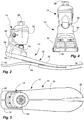
- a range of motion (ROM) prosthetic foot indicated generally at 10
- a passive dampening ankle joint indicated generally at 14
- the (ROM) prosthetic foot 10 and the passive dampening ankle joint 14 can have limited dorsiflexion-plantarflexion (up and down) pivoting to accommodate different environments, such as inclined terrain, by allowing a foot or foot keel 18 to pivot about a horizontal medial-lateral (lateral side-to-side) pivot axis 22 to accommodate the incline.
- the foot keel 18 can pivot in plantarflexion (toe pivoting downwardly) when a downward slope is encountered; or the foot keel 18 can pivot in dorsiflexion (toe pivoting upwardly) when an upward slop is encountered.
- the ankle joint 14 of the ROM foot 10 is affixed to a prosthetic foot or a foot keel 18, and has a standard fixture or attachment 26 to allow attachment to a pylon or socket to receive a remnant limb of an amputee.
- the prosthetic foot or foot keel 18 is coupled to the attachment 26.
- the prosthetic foot 10 or foot keel 18 can include an elongated forefoot keel 30 and an elongated footplate 34 coupled to the forefoot keel.
- the forefoot keel 30 can extend between a toe location 38 of a natural foot and near a heel location 42 of a natural foot.
- the footplate 34 can be coupled to the forefoot keel 30 at the toe location 38, such as with a composite wrap wrapping the distal ends of the forefoot keel and footplate.
- the footplate 34 can extend between the toe location 38 and the heel location 42.
- the foot keel 18, or the forefoot keel 30 and the footplate 34 can be formed of a composite material, namely carbon fiber in a resin matrix.
- the foot keel 18, or the forefoot keel 30 and the footplate 34 can form springs, such as leaf springs, that are resilient and bendable or compressible under load to store energy in the springs when deflected, and return the energy from the springs when released.
- the foot keel 18 can bend to store energy that is returned or released during toe-off.
- the foot keel, or the forefoot keel and/or the footplate can be bifurcated wholly or partially to adjust for or accommodate uneven terrain. As shown, the forefoot keel and the footplate are partially bifurcated from the toe location through an arch location.
- the ankle joint 14 is coupled between the attachment 26 and the prosthetic foot or foot keel 18, or forefoot keel 30.
- the ankle joint 14 dampens the limited pivoting of the foot keel 18 in the dorsiflexion-plantarflexion (up and down) direction, and also biases the foot keel 18 to pivot in a dorsiflexion (toe up) direction, and thus resists the foot keel from pivoting in a plantarflexion (toe down) direction, to provide a more natural action of the foot/ankle.
- the foot keel 18 is drawn to a more natural position, i.e. toe up, to resist settling to a downward position that can become inadvertently snagged upon sudden use.
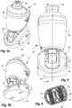
- the ankle joint 14 has an upper housing or body 50 pivotally coupled to a lower base or ankle platform 54 at the pivot axis 22.
- the base or ankle platform 54 can be attached or affixed to the foot keel 18 or forefoot keel 30, while the body 50 is affixed or rigidly attached to the attachment 26, and thus the pylon or socket.
- the ankle platform 54 can be rigidly affixed to a proximal end of the forefoot keel 30.
- the attachment 26 can be rigidly mounted on the housing or body 50.
- the attachment can form a cap or top cover to the body.
- a cover portion can be integrally formed together with the attachment and can cover the body or be flush therewith.
- the body 50 can be pivotally attached to the ankle platform 54 by an ankle pin, which can define the pivot axis 22.
- the pivotal attachment can include associated bushings and/or bearings.
- the pivot axis 22 is located at a rear of the housing or body 50, and/or at a rear of the base or ankle platform 54.
- the body 50 can have a rear lobe 58 extending downward from the body at a rear of the body.
- the pivot axis 22 can be located in a bottom of the lobe.
- the lobe 58 and ankle pin or pivot axis can be received in a slot or cavity 62 in the ankle platform 54.
- the ankle pin can extend through the ankle platform, slot and lobe of the body.
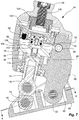
- the ankle joint 14 includes a hydraulic piston/cylinder that is disposed in the housing or body 50, and coupled to the base or ankle platform 54, to dampen pivotal movement between the housing and the base, or between the body and ankle platform, and thus between the foot keel and the leg (or attachment).
- a hollow or cylinder 66 is defined in the housing 50.
- a piston 70 is movably received and reciprocally received in the cylinder 66, and separates the cylinder into a pair of opposite chambers on opposite sides of the piston.
- a rod 74 is coupled to the piston, and extends out of the housing or body 50 to be coupled to the base or ankle platform 54 by a clevis 78.
- the clevis 78 can be pivotally coupled to the piston or rod 74 thereof and the ankle platform 54 by pins and associated bushings or bearings.
- the clevis 78 allows the piston 70 to move linearly in the cylinder 66 even though the housing or body 50 is pivotally coupled to the base or ankle platform 54.
- the clevis 78 reduces wear on the piston and cylinder by keeping side loads off the piston rod.
- the clevis 78 can define a link pivotally coupled between the piston 70 or rod 74 and the ankle platform 54.
- the pivot axis 22 is disposed rearwardly with respect to the link or clevis 78, and the link or clevis 78 is disposed forwardly of the pivot axis 22.
- the pivot axis 22 is disposed at a rear of the ankle platform 54 and body 50 nearer a rear of the foot than the link or clevis 78; and the link or clevis 78 can be pivotally coupled at a front of the ankle platform 54 forward of the pivot axis 22.
- the foot 10 and the ankle joint 14 provide a rear pivot behind the link or clevis 78 that is believed and been found to provide a smoother feel with respect to a forward pivot, even though the rear pivot results in non-bio mimicry.
- the pivot axis 22 can be located rearward of an ankle location of a natural foot.
- An axis of the attachment 26, the link (or clevis 78) and a pivot axis 56 of the link (or clevis 78) to the ankle platform 54 can be substantially aligned, with the attachment 26 and the piston 70 being disposed over the link or clevis 78, as shown in FIG. 7 .
- the link or clevis 78 can extend into a slot or cavity of the ankle platform.
- hydraulic fluid passages such as a pair of flow channels extending between the pair of chambers.
- an upward passage can extend from a lower to an upper chamber
- a downward passage can extend from the upper to the lower chamber.
- a pair of unidirectional check valves 82 is disposed in the fluid passages, each disposed in a different one of the pair of flow channels to allow flow in only one direction.
- a pair of control valves 86 is also disposed in the fluid passages, each disposed in a different one of the pair of flow channels to vary the resistance to flow of the hydraulic fluid.
- the control valves 86 can vary the size of an orifice through which the hydraulic fluid passes.
- the control valves can be infinitely adjustable between two extremes, as opposed to being discreetly adjustable at predefined orifice sizes between two extremes.
- the control valves can continuously vary the size of the orifice.
- the control valves only control the size of the orifice, without completely closing the orifice.
- the piston can always be free to move, and the foot keel can always be free to pivot.
- a biasing member such as a compressible coil spring 90 can be disposed in one of the chambers, such as the lower chamber, to bear against the piston 70 to bias the piston.
- the spring 90 can provide resilient resistance to plantarflexion (or lowering of the toe), and to bias the foot in dorsiflexion (or raising the toe).
- the spring 90 can raise the piston 70 and draw it further into the cylinder 66, to raise the foot keel 18.
- a bottom of the cylinder 66 can include an annular flange 94 extending from a bottom of the cylinder or body into the cylinder to form an annular groove 96. When the piston 70 is drawn downwardly, the spring 90 is compressed into the annular groove 96.
- the annular flange 94 can provide linear stability to the rod 74, and thus the piston 70.
- a bumper 98 can be disposed at an end of the cylinder 66 in one of the chambers, such as the upper chamber, that can abut to the piston 70 at an end of a stroke of the piston.
- the bumper can include a plurality of arcuate bumpers circumscribing an axis of the cylinder to balance force on the piston as it abuts the bumpers.
- the spring 90 can bias the piston 70 against or towards the bumper 98.
- the bumper 98 cushions the force of the piston against the cylinder or top thereof at the end of the stroke of the piston to provide a more comfortable feel.
- the ankle joint can include a hydraulic compensator 102 carried by the piston 70.
- the piston 70 can be a primary piston
- the cylinder 66 can be a primary cylinder.
- the hydraulic compensator 102 can include a secondary cylinder 106 disposed in the housing or body or cylinder 66 thereof, and fluidly coupled to at least one of the chambers.
- the secondary chamber 106 can be disposed in the primary piston 70 opposite the rod 74.
- a shaft 108 can extend from the piston 70 opposite the rod 74.
- the secondary chamber 106 can be formed in the shaft 108.
- the shaft 108 and the rod 74 can be integrally formed at the same time with the piston 70.
- a secondary piston 110 can be slidably disposed in the secondary cylinder 106.
- the secondary piston 110 can be carried by the primary piston 70 as well.
- a secondary channel 114 can be fluidly coupled to the secondary cylinder 106 and disposed in the primary piston 70.
- the hydraulic compensator 102 can have a very small orifice, and thus can cycle very slowly.
- the secondary or compensating piston 110 can cycle independently of the primary piston 70.
- the hydraulic compensator 102 can adjust for oil lose and/or temperature changes.
- a spring 112 can bias the secondary piston 110 to a closed or lower volume of the secondary cylinder 106.
- the hydraulic compensator 102 can have a shaft 108 in which the secondary cylinder 106 is formed and in which the secondary piston 110 is carried.
- the shaft 108 can be the same diameter as the rod 74 on the opposite side of the piston, and can extend through the primary cylinder opposite the rod, to create substantially equal volumes in the chambers on opposite sides of the primary piston.
- the primary piston and primary cylinder do not require a compensator or overflow reservoir due to unequal volumes.
- the rod 74 of the primary piston 70 can include a portion formed integrally with the piston, and a plunger eyebolt 116 fastened to the rod 74 and pivotally coupled to the ankle platform 54.
- a plunger eyebolt 116 fastened to the rod 74 and pivotally coupled to the ankle platform 54.
- the cylinder 66 can be formed in the body 50, and closed or capped by an annular top cap 102.
- the annular top cap 120 can be coupled to the body 50 with the cylinder 66 defined in the body 50 and closed by the top cap.
- the top cap 120 can be annular to receive the hydraulic accumulator 102 therein during stroking of the primary piston 70.
- the hydraulic compensator 120 can be carried by the piston 70, and disposed in the shaft 108 coupled to the piston and displaceable in the annular top cap 120 as the piston moves.
- the top cap 120 can be closed or capped by a top cap thread plug 124, which can both close the top cap, and receive a bolt or fastener 126 to secure the attachment 26 to the body 50.
- the top cap thread plug 124, and the bolt 126 and attachment 26, can be removed to allow access to the hydraulic compensator 120, or top cap 120.
- the secondary or compensator piston 110 can have a bore therein closed by a plug to allow the addition and/or removal of hydraulic fluid.
- the cop cap can have a bore therein closed by a plug to allow the addition and/or removal of hydraulic fluid.
- the secondary cylinder 106 can be closed by a plate and a C-clip.
- the check valves 82 can be inserted in through a bottom of the body, adjacent the lobe, and held and/or sealed in by plugs.
- the control valves 86 can be disposed on the lateral sides of the body, and on opposite sides from one another.
- the ankle joint 14 of the ROM foot 10 acts as follows:
- All movement of the foot keel can be dampened, or resisted, by the hydraulic piston/cylinder, with the orifices in the control valves resisting movement of the fluid, and thus movement of the piston, and thus movement of the foot keel.
- the spring draws the foot keel into dorsiflexion (toe up).
- the spring maintains the toe of the foot keel up during swing phase, and/or during rest.
- the spring can always be under compression.
- the hydraulic piston/cylinder may not have on/off valves, i.e. the control valves may not close, and thus the ankle joint may not adjust the angle of the foot keel with respect to the leg or pylon at any fixed angle.
- the ankle joint can be passive, and not dynamic, in that is may not control electronics or sensors, and may not dynamically adjust during use.
Landscapes
- Health & Medical Sciences (AREA)
- Transplantation (AREA)
- Heart & Thoracic Surgery (AREA)
- Oral & Maxillofacial Surgery (AREA)
- Engineering & Computer Science (AREA)
- Biomedical Technology (AREA)
- Cardiology (AREA)
- Vascular Medicine (AREA)
- Life Sciences & Earth Sciences (AREA)
- Animal Behavior & Ethology (AREA)
- General Health & Medical Sciences (AREA)
- Public Health (AREA)
- Veterinary Medicine (AREA)
- Orthopedic Medicine & Surgery (AREA)
- Prostheses (AREA)
Claims (11)
- Fußprothesevorrichtung, die Folgendes aufweist:a) ein Anschlussstück (26), das zum Koppeln mit einem Schaft oder Pylon gestaltet ist, der an einem verbleibenden Gliedmaßenstumpf eines/r Amputierten angebracht ist;b) eine Fußprothese, die an das Anschlussstück gekoppelt ist und einen länglichen Vorfußkiel (18), der sich zwischen einer Zehenposition eines natürlichen Fußes und nahe einer Fersenposition des natürlichen Fußes erstreckt, und eine längliche Fußplatte (34), die an der Zehenposition an den Vorfußkiel (18) gekoppelt ist und sich zwischen der Zehenposition und der Fersenposition erstreckt, beinhaltet, wobei der Vorfußkiel (18) und die Fußplatte (34) aus einem Verbundwerkstoff mit Fasern in einer Harzmatrix gebildet sind und Federn bilden, die federnd und biegsam sind, um beim Ablenkung Energie in den Federn zu speichern und bei Entspannung die Energie aus den Federn zurückgeben;c) ein passives dämpfendes Sprunggelenk (14), das zwischen dem Anschlussstück und der Fußprothese angekoppelt ist, um beschränktes Dorsiflexion-Plantarflexion-Schwenken des Fußes in Bezug auf das Anschlussstück um eine horizontale medial-laterale Schwenkachse bereitzustellen, wobei das Sprunggelenk Folgendes beinhaltet:i) eine Sprunggelenkplattform (5), die an dem Fuß angebracht ist;ii) einen Körper (50) mit einem Zylinder (66), der starr an dem Anschlussstück (26) angebracht ist und an der Schwenkachse (22) schwenkbar an die Sprunggelenkplattform (54) gekoppelt ist;iii) einen Kolben (70), der hin- und hergehend in dem Zylinder (66) angeordnet ist und den Zylinder (66) in ein Kammernpaar unterteilt, das eine obere und eine untere Kammer beinhaltet;iv) ein Paar Durchflusskanäle, die sich zwischen den zwei Kammern erstrecken;v) ein Paar Rückschlagventile (82), jeweils in einem anderen der zwei Durchflusskanäle angeordnet, die gestaltet sind, um Hydraulikfluid durch einen Kanal aus einer Kammer in eine weitere Kammer und durch einen weiteren Kanal aus der weiteren Kammer in die eine Kammer fließen zu lassen;vi) ein Paar Steuerventile (86), jeweils in einem anderen der zwei Durchflusskanäle angeordnet, die zum Verändern des Hydraulikfluid-Durchflusswiderstands angeordnet sind;vii) eine Verbindungsgliedplattform, die schwenkbar an dem und zwischen dem Kolben und der Sprunggelenkplattform angekoppelt ist; undviii) eine Feder (90), die immer auf Druck beansprucht ist und in der unteren Kammer angeordnet ist und an dem Kolben (70) anliegt, um den Kolben (70) und damit den Vorfußkiel während der Schwungphase zu heben und während des Fersenaufsetzens federnden Widerstand gegen die Plantarflexion bereitzustellen;d) die Schwenkachse (22) in Bezug auf das Verbindungsglied rückwärtig angeordnet ist und das Verbindungsglied vor der Schwenkachse (22) angeordnet ist.
- Vorrichtung nach Anspruch 1, wobei die Schwenkachse (22) an einem hinteren Bereich der Sprunkgelenkplattform (54) näher an einem hinteren Bereich des Fußes als das Verbindungsglied angeordnet ist; und wobei das Verbindungsglied schwenkbar vorn an einem vorderen Bereich der Sprunggelenkplattform (54) angekoppelt ist.
- Vorrichtung nach Anspruch 1, die ferner aufweist: eine hintere Zunge (58), die sich von dem Körper (50) an einem hinteren Bereich des Körpers (50) nach unten erstreckt; und wobei die Schwenkachse (22) sich in einem unteren Ende der Zunge (58) befindet; und die hintere Zunge (58) in einer Aussparung in der Sprunggelenkplattform (54) aufgenommen ist.
- Vorrichtung nach Anspruch 1, wobei der Kolben (70) ein Hauptkolben ist und der Zylinder (66) ein Hauptzylinder ist; und die ferner eine hydraulische Ausgleichvorrichtung (102) zum Ausgleichen von Hydraulikfluidverlust oder Temperaturänderung oder von beiden aufweist mit:a) einem sekundären Zylinder (106), der in einem Gehäuse angeordnet ist und in Strömungsverbindung mit wenigstens einer der Kammern gekoppelt ist;b) einem sekundären Kolben (110), der verschiebbar in dem sekundären Zylinder angeordnet ist;c) eine sekundäre Feder (112), die den sekundären Kolben auf ein kleineres Volumen des sekundären Zylinders vorspannt; undd) eine kleine Öffnung, so dass der sekundäre Kolben unabhängig vom Hauptkolben arbeitet.
- Vorrichtung nach Anspruch 4, wobei die Ausgleichvorrichtung (102) ferner aufweist: a) die zweite Kammer ist in dem Hauptkolben (70) angeordnet und der sekundäre Kolben (110) wird von dem Hauptkolben (70) getragen; und b) einen sekundären Kanal, der in Strömungsverbindung mit dem sekundären Zylinder (106) gekoppelt und in dem Hauptkolben (70) angeordnet ist.
- Vorrichtung nach Anspruch 1, die ferner aufweist: eine ringförmige obere Kappe (120), die an den Körper (50) angekoppelt ist, wobei der Zylinder (66) in dem Körper (50) definiert ist und mit der oberen Kappe (120) verschlossen ist; und mehrere bogenförmige Stoßfänger, die von der ringförmigen obere Kappe getragen werden und an einem Ende der oberen Kammer angeordnet sind und eine Achse des Zylinders umschreiben und an einem Ende eines Hubs des Kolbens an den Kolben anstoßen.
- Vorrichtung nach Anspruch 1, die ferner aufweist:eine Stange (74), die mit dem Kolben (70) gekoppelt ist und sich aus dem Körper (50) heraus erstreckt und schwenkbar mit dem Verbindungsglied gekoppelt ist; eine ringförmige obere Kappe (120), die mit dem Körper (50) gekoppelt ist, wobei der Zylinder (66) in dem Körper definiert ist und mit der oberen Kappe verschlossen ist; einen Schaft, der der Stange (74) gegenüber mit dem Kolben (70) gekoppelt ist und sich durch die ringförmige obere Kappe (120) erstreckt; undeine hydraulische Ausgleichvorrichtung (102), die von dem Kolben (70) getragen wird und in dem mit dem Kolben (70) gekoppelten Schaft angeordnet ist und beim Bewegen des Kolbens (70) in der ringförmigen oberen Kappe (120) verlagerungsfähig ist.
- Vorrichtung nach Anspruch 7, die ferner aufweist: einen Stopfen (124), der in der ringförmigen oberen Kappe (120) angeordnet ist; und ein Befestigungselement (126), das das Anschlussstück (26) an den Stopfen (124) und somit an den Körper (50) koppelt.
- Vorrichtung nach Anspruch 1, die ferner aufweist: eine ringförmige Nut in einem unteren Ende des Zylinders (66), wobei die Feder (90) in die ringförmige Nut hinein zusammengedrückt wird, wenn der Kolben (70) nach unten gezogen wird.
- Vorrichtung nach Anspruch 1, die ferner aufweist: eine Stange (74), die mit dem Kolben (70) gekoppelt ist und sich aus dem Körper (50) heraus erstreckt; eine Öse, die an der Stange (74) befestigt ist; und einen Gabelbügel, der schwenkbar an die Öse und die Sprunggelenkplattform gekoppelt ist und das Verbindungsglied definiert, damit sich der Kolben mit schwenkbar an die Sprunggelenkplattform (54) gekoppeltem Körper in dem Zylinder linear bewegen kann.
- Vorrichtung nach Anspruch 1, wobei jedes von dem Paar Steuerventile (86) eine Öffnung mit veränderlicher Größe aufweist, durch welche das Hydraulikfluid strömt, und ein jeweiliges Steuerventil die Größe der Öffnung mit veränderlicher Größe verändert, um den Hydraulikfluid-Durchflusswiderstand zu verändern.
Applications Claiming Priority (4)
| Application Number | Priority Date | Filing Date | Title |
|---|---|---|---|
| US201361761003P | 2013-02-05 | 2013-02-05 | |
| US13/793,892 US8986398B2 (en) | 2013-02-05 | 2013-03-11 | Hydraulic prosthetic ankle |
| EP14151179.0A EP2762109B1 (de) | 2013-02-05 | 2014-01-14 | Hydraulischer Prothesenknöchel |
| EP17170292.1A EP3272316B1 (de) | 2013-02-05 | 2014-01-14 | Hydraulischer prothesenknöchel |
Related Parent Applications (2)
| Application Number | Title | Priority Date | Filing Date |
|---|---|---|---|
| EP14151179.0A Division EP2762109B1 (de) | 2013-02-05 | 2014-01-14 | Hydraulischer Prothesenknöchel |
| EP17170292.1A Division EP3272316B1 (de) | 2013-02-05 | 2014-01-14 | Hydraulischer prothesenknöchel |
Publications (2)
| Publication Number | Publication Date |
|---|---|
| EP3563808A1 EP3563808A1 (de) | 2019-11-06 |
| EP3563808B1 true EP3563808B1 (de) | 2021-04-21 |
Family
ID=49918630
Family Applications (3)
| Application Number | Title | Priority Date | Filing Date |
|---|---|---|---|
| EP14151179.0A Active EP2762109B1 (de) | 2013-02-05 | 2014-01-14 | Hydraulischer Prothesenknöchel |
| EP17170292.1A Active EP3272316B1 (de) | 2013-02-05 | 2014-01-14 | Hydraulischer prothesenknöchel |
| EP19162386.7A Active EP3563808B1 (de) | 2013-02-05 | 2014-01-14 | Hydraulischer prothetischer knöchel |
Family Applications Before (2)
| Application Number | Title | Priority Date | Filing Date |
|---|---|---|---|
| EP14151179.0A Active EP2762109B1 (de) | 2013-02-05 | 2014-01-14 | Hydraulischer Prothesenknöchel |
| EP17170292.1A Active EP3272316B1 (de) | 2013-02-05 | 2014-01-14 | Hydraulischer prothesenknöchel |
Country Status (2)
| Country | Link |
|---|---|
| US (1) | US8986398B2 (de) |
| EP (3) | EP2762109B1 (de) |
Families Citing this family (23)
| Publication number | Priority date | Publication date | Assignee | Title |
|---|---|---|---|---|
| US6260875B1 (en) | 1998-06-19 | 2001-07-17 | Textron Automotive Company | Seamless/integral DSIR or PSIR door configuration in hard plastic trim application facilitated by gas |
| US10335291B2 (en) * | 2012-07-27 | 2019-07-02 | Proteor | Hydraulic system for a knee-ankle assembly controlled by a microprocessor |
| US9028557B2 (en) | 2013-03-14 | 2015-05-12 | Freedom Innovations, Llc | Prosthetic with voice coil valve |
| US12144748B2 (en) | 2013-08-27 | 2024-11-19 | Proteor USA, LLC | Microprocessor controlled prosthetic ankle system for footwear and terrain adaptation |
| US9763809B2 (en) | 2013-08-27 | 2017-09-19 | Freedom Innovations, Llc | Microprocessor controlled prosthetic ankle system for footwear and terrain adaptation |
| JP6929775B2 (ja) | 2014-12-18 | 2021-09-01 | オットーボック・エスイー・ウント・コンパニー・カーゲーアーアー | 位置および変化速度に対する機械的反応システムを有する人工関節 |
| US10702403B2 (en) * | 2014-12-18 | 2020-07-07 | Ottobock Se & Co. Kgaa | Prosthetic joint |
| US20160296336A1 (en) | 2015-04-07 | 2016-10-13 | Gerhard E. Maale | Torsionally Stabilized Endoprosthetic Device |
| DE102015207936B3 (de) * | 2015-04-29 | 2016-09-01 | Otto Bock Healthcare Gmbh | Fußprothese |
| DE102015107783A1 (de) * | 2015-05-18 | 2016-11-24 | Inventus Engineering Gmbh | Prothesen- oder Exoskelettkomponente, Prothesen- oder Exoskelett und Verfahren |
| US9861493B2 (en) | 2015-08-14 | 2018-01-09 | Gerhard E. Maale | Glenoid fossa prosthesis |
| US10485670B2 (en) | 2015-08-14 | 2019-11-26 | Gerhard E. Maale | Glenoid fossa prosthesis |
| DE102016125081B3 (de) | 2016-12-21 | 2018-05-30 | Ken Dall Enterprise Co., Ltd. | Hydraulisches Fußgelenk |
| US12064360B2 (en) * | 2019-11-09 | 2024-08-20 | Tarbiat Modares University | Prosthetic foot |
| WO2021154185A1 (en) * | 2020-01-27 | 2021-08-05 | Proted Protez Ortez Ve Rehabilitasyon Ltd. Sti. | Hydraulic actuator enabling to control dorsiflexion and plantar flexion speeds of the prosthetic foot joint |
| CN113288531B (zh) * | 2021-05-10 | 2022-05-20 | 吉林大学 | 一种多轴踝关节假肢 |
| US20230125274A1 (en) * | 2021-10-21 | 2023-04-27 | Motion Control, Inc. | Prosthetic Foot and Ankle System with Damper |
| CN118302134A (zh) * | 2021-12-31 | 2024-07-05 | 奥托博克健康康复公司 | 用于关节连接式踝部的系统和方法 |
| CN115969589A (zh) * | 2022-12-12 | 2023-04-18 | 云南省康复辅具技术中心 | 一种脚部假肢 |
| CN121548396A (zh) * | 2023-06-30 | 2026-02-17 | 奥托·博克保健有限合伙公司 | 用于可活动假体关节的系统及方法 |
| WO2025136937A1 (en) * | 2023-12-20 | 2025-06-26 | Otto Bock Healthcare Lp | Devices and methods for aligning prosthetic and orthotic components |
| CN118415799A (zh) * | 2024-05-24 | 2024-08-02 | 国家康复辅具研究中心 | 仿生液压踝关节阻尼缸 |
| CN119184927B (zh) * | 2024-10-17 | 2025-08-05 | 电子科技大学 | 一种液压储能踝关节 |
Family Cites Families (26)
| Publication number | Priority date | Publication date | Assignee | Title |
|---|---|---|---|---|
| US2470480A (en) | 1946-04-23 | 1949-05-17 | Stanley R Fogg | Artificial foot |
| DE1069827B (de) | 1956-11-26 | |||
| AT334521B (de) | 1974-03-08 | 1976-01-25 | Forsch Orthopadie Technik | Sprunggelenk |
| JPS59183747A (ja) * | 1983-04-04 | 1984-10-18 | 工業技術院長 | 動力義足における足首作動機構 |
| US5290319A (en) | 1991-02-28 | 1994-03-01 | Phillips L Van | Prosthetic foot incorporating adjustable bladders |
| FR2692952B1 (fr) | 1992-06-25 | 1996-04-05 | Psi | Amortisseurs perfectionnes a limite de deplacement. |
| DE4410730C1 (de) | 1994-03-28 | 1995-06-08 | Biedermann Motech Gmbh | Schwungphasensteuerung für ein künstliches Kniegelenk |
| SE502951C2 (sv) | 1994-10-07 | 1996-02-26 | Gramtec Innovation Ab | Rotationsdämpare vid knäledsprotes |
| SE511750C2 (sv) | 1995-02-21 | 1999-11-15 | Gramtec Innovation Ab | Ställbar protesled, såsom protesankel eller protesfot |
| GB2311466B (en) | 1996-03-29 | 1999-11-10 | Steeper Hugh Ltd | A prosthetic foot |
| US5810130A (en) * | 1997-03-14 | 1998-09-22 | General Motors Corporation | Suspension damper with rebound cut-off |
| SE515958C2 (sv) | 1999-06-10 | 2001-11-05 | Gramtec Innovation Ab | Anordning vid en benprotes försedd med en fot |
| JP3570619B2 (ja) | 1999-11-15 | 2004-09-29 | 株式会社ナブコ | 義足用エアシリンダ装置 |
| US6875241B2 (en) | 2000-06-30 | 2005-04-05 | Roland J. Christensen, As Operating Manager Of Rjc Development Lc, General Partner Of The Roland J. Christensen Family Limited Partnership | Variable resistance cell |
| SE516947C2 (sv) | 2000-08-25 | 2002-03-26 | Gramtec Innovation Ab | Anordning vid benprotes |
| US6443993B1 (en) | 2001-03-23 | 2002-09-03 | Wayne Koniuk | Self-adjusting prosthetic ankle apparatus |
| US7507259B2 (en) | 2001-03-30 | 2009-03-24 | Bioquest Prosthetics, Llc | Prosthetic foot with tunable performance |
| US7942935B2 (en) | 2005-03-29 | 2011-05-17 | Motion Control | Device and system for prosthetic knees and ankles |
| WO2007054736A2 (en) * | 2005-11-14 | 2007-05-18 | Chas. A. Blatchford & Sons Limited | An adjustment device for a lower limb prosthesis |
| US7862622B2 (en) | 2006-06-08 | 2011-01-04 | College Park Industries, Inc. | Prosthetic foot with adjustable heel height |
| GB0701662D0 (en) | 2006-12-14 | 2007-03-07 | Blatchford & Sons Ltd | A lower limb prosthesis |
| US7985265B2 (en) | 2006-12-14 | 2011-07-26 | Chas. A. Blatchford & Sons Limited | Prosthetic ankle and foot combination |
| WO2009120637A1 (en) | 2008-03-24 | 2009-10-01 | Ossur Hf | Transfemoral prosthetic systems and methods for operating the same |
| US20110082566A1 (en) * | 2008-09-04 | 2011-04-07 | Herr Hugh M | Implementing a stand-up sequence using a lower-extremity prosthesis or orthosis |
| GB0819554D0 (en) * | 2008-10-27 | 2008-12-03 | Orthomobility Ltd | A prosthetic hydraulic joint |
| IT1396692B1 (it) | 2009-11-18 | 2012-12-14 | Rizzoli Ortopedia S P A | Struttura di protesi per amputati agli arti inferiori. |
-
2013
- 2013-03-11 US US13/793,892 patent/US8986398B2/en active Active
-
2014
- 2014-01-14 EP EP14151179.0A patent/EP2762109B1/de active Active
- 2014-01-14 EP EP17170292.1A patent/EP3272316B1/de active Active
- 2014-01-14 EP EP19162386.7A patent/EP3563808B1/de active Active
Also Published As
| Publication number | Publication date |
|---|---|
| US20140222167A1 (en) | 2014-08-07 |
| EP3272316B1 (de) | 2019-03-13 |
| EP3563808A1 (de) | 2019-11-06 |
| EP2762109B1 (de) | 2017-05-10 |
| EP2762109A1 (de) | 2014-08-06 |
| EP3272316A1 (de) | 2018-01-24 |
| US8986398B2 (en) | 2015-03-24 |
Similar Documents
| Publication | Publication Date | Title |
|---|---|---|
| US8986398B2 (en) | Hydraulic prosthetic ankle | |
| US7686848B2 (en) | Prosthetic foot with energy transfer | |
| US11679008B2 (en) | Prosthetic ankle joint mechanism | |
| US11246723B2 (en) | Lower limb prosthesis comprising a hydraulic damping and a vacuum generating mechanism | |
| US8628585B2 (en) | Lower limb prosthesis | |
| EP2879623B1 (de) | Gelenkprothesenmodul | |
| US7963998B2 (en) | Hip joint prosthesis | |
| US7066964B2 (en) | Prosthetic knee and rotary hydraulic chamber | |
| US20030120353A1 (en) | Variable resistance cell | |
| US20130073056A1 (en) | Dorsi-plantar prosthetic ankle module | |
| US20060229736A1 (en) | Prosthetic foot with energy transfer | |
| US20200054465A1 (en) | Lower limb prosthesis | |
| US20130030549A1 (en) | Leg Prosthesis | |
| US20060241783A1 (en) | Variable resistance cell | |
| DE112012000673B4 (de) | Unterschenkelprothese | |
| US20050216098A1 (en) | Variable resistance cell | |
| US7909885B2 (en) | Swing-phase controller with an artificial joint | |
| CN121548396A (zh) | 用于可活动假体关节的系统及方法 | |
| JP2022117699A (ja) | 歩行補助装置 |
Legal Events
| Date | Code | Title | Description |
|---|---|---|---|
| PUAI | Public reference made under article 153(3) epc to a published international application that has entered the european phase |
Free format text: ORIGINAL CODE: 0009012 |
|
| STAA | Information on the status of an ep patent application or granted ep patent |
Free format text: STATUS: THE APPLICATION HAS BEEN PUBLISHED |
|
| AC | Divisional application: reference to earlier application |
Ref document number: 3272316 Country of ref document: EP Kind code of ref document: P Ref document number: 2762109 Country of ref document: EP Kind code of ref document: P |
|
| AK | Designated contracting states |
Kind code of ref document: A1 Designated state(s): AL AT BE BG CH CY CZ DE DK EE ES FI FR GB GR HR HU IE IS IT LI LT LU LV MC MK MT NL NO PL PT RO RS SE SI SK SM TR |
|
| STAA | Information on the status of an ep patent application or granted ep patent |
Free format text: STATUS: REQUEST FOR EXAMINATION WAS MADE |
|
| 17P | Request for examination filed |
Effective date: 20200505 |
|
| RBV | Designated contracting states (corrected) |
Designated state(s): AL AT BE BG CH CY CZ DE DK EE ES FI FR GB GR HR HU IE IS IT LI LT LU LV MC MK MT NL NO PL PT RO RS SE SI SK SM TR |
|
| RIC1 | Information provided on ipc code assigned before grant |
Ipc: A61F 2/74 20060101ALN20200928BHEP Ipc: A61F 2/66 20060101AFI20200928BHEP Ipc: A61F 2/68 20060101ALN20200928BHEP Ipc: A61F 2/50 20060101ALN20200928BHEP |
|
| GRAP | Despatch of communication of intention to grant a patent |
Free format text: ORIGINAL CODE: EPIDOSNIGR1 |
|
| STAA | Information on the status of an ep patent application or granted ep patent |
Free format text: STATUS: GRANT OF PATENT IS INTENDED |
|
| RIC1 | Information provided on ipc code assigned before grant |
Ipc: A61F 2/74 20060101ALN20201021BHEP Ipc: A61F 2/68 20060101ALN20201021BHEP Ipc: A61F 2/66 20060101AFI20201021BHEP Ipc: A61F 2/50 20060101ALN20201021BHEP |
|
| INTG | Intention to grant announced |
Effective date: 20201112 |
|
| GRAS | Grant fee paid |
Free format text: ORIGINAL CODE: EPIDOSNIGR3 |
|
| GRAA | (expected) grant |
Free format text: ORIGINAL CODE: 0009210 |
|
| STAA | Information on the status of an ep patent application or granted ep patent |
Free format text: STATUS: THE PATENT HAS BEEN GRANTED |
|
| AC | Divisional application: reference to earlier application |
Ref document number: 3272316 Country of ref document: EP Kind code of ref document: P Ref document number: 2762109 Country of ref document: EP Kind code of ref document: P |
|
| AK | Designated contracting states |
Kind code of ref document: B1 Designated state(s): AL AT BE BG CH CY CZ DE DK EE ES FI FR GB GR HR HU IE IS IT LI LT LU LV MC MK MT NL NO PL PT RO RS SE SI SK SM TR |
|
| RAP1 | Party data changed (applicant data changed or rights of an application transferred) |
Owner name: PROTEOR USA, LLC |
|
| REG | Reference to a national code |
Ref country code: GB Ref legal event code: FG4D |
|
| REG | Reference to a national code |
Ref country code: CH Ref legal event code: EP |
|
| REG | Reference to a national code |
Ref country code: DE Ref legal event code: R096 Ref document number: 602014076919 Country of ref document: DE Ref country code: IE Ref legal event code: FG4D |
|
| REG | Reference to a national code |
Ref country code: AT Ref legal event code: REF Ref document number: 1383852 Country of ref document: AT Kind code of ref document: T Effective date: 20210515 |
|
| REG | Reference to a national code |
Ref country code: LT Ref legal event code: MG9D |
|
| REG | Reference to a national code |
Ref country code: AT Ref legal event code: MK05 Ref document number: 1383852 Country of ref document: AT Kind code of ref document: T Effective date: 20210421 |
|
| REG | Reference to a national code |
Ref country code: NL Ref legal event code: MP Effective date: 20210421 |
|
| PG25 | Lapsed in a contracting state [announced via postgrant information from national office to epo] |
Ref country code: FI Free format text: LAPSE BECAUSE OF FAILURE TO SUBMIT A TRANSLATION OF THE DESCRIPTION OR TO PAY THE FEE WITHIN THE PRESCRIBED TIME-LIMIT Effective date: 20210421 Ref country code: HR Free format text: LAPSE BECAUSE OF FAILURE TO SUBMIT A TRANSLATION OF THE DESCRIPTION OR TO PAY THE FEE WITHIN THE PRESCRIBED TIME-LIMIT Effective date: 20210421 Ref country code: LT Free format text: LAPSE BECAUSE OF FAILURE TO SUBMIT A TRANSLATION OF THE DESCRIPTION OR TO PAY THE FEE WITHIN THE PRESCRIBED TIME-LIMIT Effective date: 20210421 Ref country code: NL Free format text: LAPSE BECAUSE OF FAILURE TO SUBMIT A TRANSLATION OF THE DESCRIPTION OR TO PAY THE FEE WITHIN THE PRESCRIBED TIME-LIMIT Effective date: 20210421 Ref country code: AT Free format text: LAPSE BECAUSE OF FAILURE TO SUBMIT A TRANSLATION OF THE DESCRIPTION OR TO PAY THE FEE WITHIN THE PRESCRIBED TIME-LIMIT Effective date: 20210421 Ref country code: BG Free format text: LAPSE BECAUSE OF FAILURE TO SUBMIT A TRANSLATION OF THE DESCRIPTION OR TO PAY THE FEE WITHIN THE PRESCRIBED TIME-LIMIT Effective date: 20210721 |
|
| PG25 | Lapsed in a contracting state [announced via postgrant information from national office to epo] |
Ref country code: GR Free format text: LAPSE BECAUSE OF FAILURE TO SUBMIT A TRANSLATION OF THE DESCRIPTION OR TO PAY THE FEE WITHIN THE PRESCRIBED TIME-LIMIT Effective date: 20210722 Ref country code: NO Free format text: LAPSE BECAUSE OF FAILURE TO SUBMIT A TRANSLATION OF THE DESCRIPTION OR TO PAY THE FEE WITHIN THE PRESCRIBED TIME-LIMIT Effective date: 20210721 Ref country code: LV Free format text: LAPSE BECAUSE OF FAILURE TO SUBMIT A TRANSLATION OF THE DESCRIPTION OR TO PAY THE FEE WITHIN THE PRESCRIBED TIME-LIMIT Effective date: 20210421 Ref country code: PL Free format text: LAPSE BECAUSE OF FAILURE TO SUBMIT A TRANSLATION OF THE DESCRIPTION OR TO PAY THE FEE WITHIN THE PRESCRIBED TIME-LIMIT Effective date: 20210421 Ref country code: RS Free format text: LAPSE BECAUSE OF FAILURE TO SUBMIT A TRANSLATION OF THE DESCRIPTION OR TO PAY THE FEE WITHIN THE PRESCRIBED TIME-LIMIT Effective date: 20210421 Ref country code: SE Free format text: LAPSE BECAUSE OF FAILURE TO SUBMIT A TRANSLATION OF THE DESCRIPTION OR TO PAY THE FEE WITHIN THE PRESCRIBED TIME-LIMIT Effective date: 20210421 Ref country code: PT Free format text: LAPSE BECAUSE OF FAILURE TO SUBMIT A TRANSLATION OF THE DESCRIPTION OR TO PAY THE FEE WITHIN THE PRESCRIBED TIME-LIMIT Effective date: 20210823 |
|
| REG | Reference to a national code |
Ref country code: DE Ref legal event code: R097 Ref document number: 602014076919 Country of ref document: DE |
|
| PG25 | Lapsed in a contracting state [announced via postgrant information from national office to epo] |
Ref country code: RO Free format text: LAPSE BECAUSE OF FAILURE TO SUBMIT A TRANSLATION OF THE DESCRIPTION OR TO PAY THE FEE WITHIN THE PRESCRIBED TIME-LIMIT Effective date: 20210421 Ref country code: SM Free format text: LAPSE BECAUSE OF FAILURE TO SUBMIT A TRANSLATION OF THE DESCRIPTION OR TO PAY THE FEE WITHIN THE PRESCRIBED TIME-LIMIT Effective date: 20210421 Ref country code: CZ Free format text: LAPSE BECAUSE OF FAILURE TO SUBMIT A TRANSLATION OF THE DESCRIPTION OR TO PAY THE FEE WITHIN THE PRESCRIBED TIME-LIMIT Effective date: 20210421 Ref country code: DK Free format text: LAPSE BECAUSE OF FAILURE TO SUBMIT A TRANSLATION OF THE DESCRIPTION OR TO PAY THE FEE WITHIN THE PRESCRIBED TIME-LIMIT Effective date: 20210421 Ref country code: SK Free format text: LAPSE BECAUSE OF FAILURE TO SUBMIT A TRANSLATION OF THE DESCRIPTION OR TO PAY THE FEE WITHIN THE PRESCRIBED TIME-LIMIT Effective date: 20210421 Ref country code: ES Free format text: LAPSE BECAUSE OF FAILURE TO SUBMIT A TRANSLATION OF THE DESCRIPTION OR TO PAY THE FEE WITHIN THE PRESCRIBED TIME-LIMIT Effective date: 20210421 Ref country code: EE Free format text: LAPSE BECAUSE OF FAILURE TO SUBMIT A TRANSLATION OF THE DESCRIPTION OR TO PAY THE FEE WITHIN THE PRESCRIBED TIME-LIMIT Effective date: 20210421 |
|
| PLBE | No opposition filed within time limit |
Free format text: ORIGINAL CODE: 0009261 |
|
| STAA | Information on the status of an ep patent application or granted ep patent |
Free format text: STATUS: NO OPPOSITION FILED WITHIN TIME LIMIT |
|
| 26N | No opposition filed |
Effective date: 20220124 |
|
| PG25 | Lapsed in a contracting state [announced via postgrant information from national office to epo] |
Ref country code: AL Free format text: LAPSE BECAUSE OF FAILURE TO SUBMIT A TRANSLATION OF THE DESCRIPTION OR TO PAY THE FEE WITHIN THE PRESCRIBED TIME-LIMIT Effective date: 20210421 |
|
| PG25 | Lapsed in a contracting state [announced via postgrant information from national office to epo] |
Ref country code: IT Free format text: LAPSE BECAUSE OF FAILURE TO SUBMIT A TRANSLATION OF THE DESCRIPTION OR TO PAY THE FEE WITHIN THE PRESCRIBED TIME-LIMIT Effective date: 20210421 |
|
| PG25 | Lapsed in a contracting state [announced via postgrant information from national office to epo] |
Ref country code: MC Free format text: LAPSE BECAUSE OF FAILURE TO SUBMIT A TRANSLATION OF THE DESCRIPTION OR TO PAY THE FEE WITHIN THE PRESCRIBED TIME-LIMIT Effective date: 20210421 |
|
| REG | Reference to a national code |
Ref country code: CH Ref legal event code: PL |
|
| REG | Reference to a national code |
Ref country code: BE Ref legal event code: MM Effective date: 20220131 |
|
| PG25 | Lapsed in a contracting state [announced via postgrant information from national office to epo] |
Ref country code: LU Free format text: LAPSE BECAUSE OF NON-PAYMENT OF DUE FEES Effective date: 20220114 |
|
| PG25 | Lapsed in a contracting state [announced via postgrant information from national office to epo] |
Ref country code: BE Free format text: LAPSE BECAUSE OF NON-PAYMENT OF DUE FEES Effective date: 20220131 |
|
| PG25 | Lapsed in a contracting state [announced via postgrant information from national office to epo] |
Ref country code: LI Free format text: LAPSE BECAUSE OF NON-PAYMENT OF DUE FEES Effective date: 20220131 Ref country code: CH Free format text: LAPSE BECAUSE OF NON-PAYMENT OF DUE FEES Effective date: 20220131 |
|
| PG25 | Lapsed in a contracting state [announced via postgrant information from national office to epo] |
Ref country code: IE Free format text: LAPSE BECAUSE OF NON-PAYMENT OF DUE FEES Effective date: 20220114 |
|
| P01 | Opt-out of the competence of the unified patent court (upc) registered |
Effective date: 20230630 |
|
| PG25 | Lapsed in a contracting state [announced via postgrant information from national office to epo] |
Ref country code: MK Free format text: LAPSE BECAUSE OF FAILURE TO SUBMIT A TRANSLATION OF THE DESCRIPTION OR TO PAY THE FEE WITHIN THE PRESCRIBED TIME-LIMIT Effective date: 20210421 Ref country code: CY Free format text: LAPSE BECAUSE OF FAILURE TO SUBMIT A TRANSLATION OF THE DESCRIPTION OR TO PAY THE FEE WITHIN THE PRESCRIBED TIME-LIMIT Effective date: 20210421 |
|
| PG25 | Lapsed in a contracting state [announced via postgrant information from national office to epo] |
Ref country code: HU Free format text: LAPSE BECAUSE OF FAILURE TO SUBMIT A TRANSLATION OF THE DESCRIPTION OR TO PAY THE FEE WITHIN THE PRESCRIBED TIME-LIMIT; INVALID AB INITIO Effective date: 20140114 |
|
| PG25 | Lapsed in a contracting state [announced via postgrant information from national office to epo] |
Ref country code: MT Free format text: LAPSE BECAUSE OF FAILURE TO SUBMIT A TRANSLATION OF THE DESCRIPTION OR TO PAY THE FEE WITHIN THE PRESCRIBED TIME-LIMIT Effective date: 20210421 |
|
| PGFP | Annual fee paid to national office [announced via postgrant information from national office to epo] |
Ref country code: TR Payment date: 20250109 Year of fee payment: 12 |
|
| PGFP | Annual fee paid to national office [announced via postgrant information from national office to epo] |
Ref country code: GB Payment date: 20251120 Year of fee payment: 13 |
|
| PGFP | Annual fee paid to national office [announced via postgrant information from national office to epo] |
Ref country code: FR Payment date: 20251124 Year of fee payment: 13 |
|
| PGFP | Annual fee paid to national office [announced via postgrant information from national office to epo] |
Ref country code: DE Payment date: 20251119 Year of fee payment: 13 |
|
| PGFP | Annual fee paid to national office [announced via postgrant information from national office to epo] |
Ref country code: IS Payment date: 20260112 Year of fee payment: 13 |