EP3563561B1 - Unterdrückung von akustischem echo - Google Patents
Unterdrückung von akustischem echo Download PDFInfo
- Publication number
- EP3563561B1 EP3563561B1 EP17808950.4A EP17808950A EP3563561B1 EP 3563561 B1 EP3563561 B1 EP 3563561B1 EP 17808950 A EP17808950 A EP 17808950A EP 3563561 B1 EP3563561 B1 EP 3563561B1
- Authority
- EP
- European Patent Office
- Prior art keywords
- multiplicity
- signal
- transfer functions
- estimated
- microphone
- Prior art date
- Legal status (The legal status is an assumption and is not a legal conclusion. Google has not performed a legal analysis and makes no representation as to the accuracy of the status listed.)
- Active
Links
Images
Classifications
-
- H—ELECTRICITY
- H04—ELECTRIC COMMUNICATION TECHNIQUE
- H04M—TELEPHONIC COMMUNICATION
- H04M9/00—Arrangements for interconnection not involving centralised switching
- H04M9/08—Two-way loud-speaking telephone systems with means for conditioning the signal, e.g. for suppressing echoes for one or both directions of traffic
- H04M9/082—Two-way loud-speaking telephone systems with means for conditioning the signal, e.g. for suppressing echoes for one or both directions of traffic using echo cancellers
-
- G—PHYSICS
- G10—MUSICAL INSTRUMENTS; ACOUSTICS
- G10L—SPEECH ANALYSIS TECHNIQUES OR SPEECH SYNTHESIS; SPEECH RECOGNITION; SPEECH OR VOICE PROCESSING TECHNIQUES; SPEECH OR AUDIO CODING OR DECODING
- G10L21/00—Speech or voice signal processing techniques to produce another audible or non-audible signal, e.g. visual or tactile, in order to modify its quality or its intelligibility
- G10L21/02—Speech enhancement, e.g. noise reduction or echo cancellation
- G10L21/0208—Noise filtering
- G10L21/0216—Noise filtering characterised by the method used for estimating noise
- G10L21/0232—Processing in the frequency domain
-
- G—PHYSICS
- G06—COMPUTING OR CALCULATING; COUNTING
- G06F—ELECTRIC DIGITAL DATA PROCESSING
- G06F17/00—Digital computing or data processing equipment or methods, specially adapted for specific functions
- G06F17/10—Complex mathematical operations
- G06F17/17—Function evaluation by approximation methods, e.g. inter- or extrapolation, smoothing, least mean square method
-
- H—ELECTRICITY
- H04—ELECTRIC COMMUNICATION TECHNIQUE
- H04R—LOUDSPEAKERS, MICROPHONES, GRAMOPHONE PICK-UPS OR LIKE ACOUSTIC ELECTROMECHANICAL TRANSDUCERS; ELECTRIC HEARING AIDS; PUBLIC ADDRESS SYSTEMS
- H04R3/00—Circuits for transducers
- H04R3/04—Circuits for transducers for correcting frequency response
-
- G—PHYSICS
- G10—MUSICAL INSTRUMENTS; ACOUSTICS
- G10L—SPEECH ANALYSIS TECHNIQUES OR SPEECH SYNTHESIS; SPEECH RECOGNITION; SPEECH OR VOICE PROCESSING TECHNIQUES; SPEECH OR AUDIO CODING OR DECODING
- G10L21/00—Speech or voice signal processing techniques to produce another audible or non-audible signal, e.g. visual or tactile, in order to modify its quality or its intelligibility
- G10L21/02—Speech enhancement, e.g. noise reduction or echo cancellation
- G10L21/0208—Noise filtering
- G10L2021/02082—Noise filtering the noise being echo, reverberation of the speech
Definitions
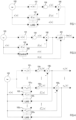
- Figure 1 is a signal flow diagram illustrating the principle of adaptive system identification applicable in acoustic echo cancellation (AEC).
- AEC acoustic echo cancellation
- Figure 1 refers to an acoustic echo canceler operating in the time domain but other acoustic echo cancelers, e.g., operating in sub-bands or in the frequency domain, are applicable as well.
- Acoustic echo cancellation can be attained, e.g., by subtracting from a total sound signal containing echoes an estimated echo signal representing an estimate of these echoes.
- algorithms have been developed that operate in the time domain and that may employ adaptive digital filters for processing time-discrete signals.
- an unknown system 101 and an adaptive filter 102 operate in parallel.
- the unknown system 101 converts, according to its transfer function w(n), an input signal x(n) from a signal source 103 into a signal y(n).
- the signal source 103 may be a loudspeaker and input signal x(n) may be a signal supplied to and reproduced by the loudspeaker.
- Signal y(n) may be an output signal of a microphone 104 that picks up sound reproduced by the loudspeaker and transferred via the unknown system 101 to the microphone 104.
- the adaptive filter 102 converts, according to its transfer function w ⁇ (n), the input signal x(n) into a signal d ⁇ (n).
- the signal y(n) which is the input signal x(n) distorted by the unknown system 101 having the unknown transfer function w(n), serves as a desired signal.
- the output of the adaptive filter 102 i.e., the signal d ⁇ (n) is deducted from the input signal x(n) by the adaptive filter 102 under control of a filter controller 105 dependent on the input signal x(n) and an error signal e(n).
- the filter controller 105 adjusts filter coefficients of the adaptive filter 102 in an iteration loop such that the error signal e(n), which is the difference between the signal y(n) and signal d ⁇ (n) as represented by a subtractor 106 in Figure 1 , is minimized.
- the signal d ⁇ (n) approaches signal y(n) and the unknown transfer function w(n) is approximated by transfer function w ⁇ (n) so that, in terms of cancellation, maximum elimination of the signal y(n), e.g, an echo signal, is attained by the signal d ⁇ (n).
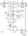
- FIG. 2 An acoustic echo canceler with an overlap-save based, frequency domain adaptive filter is shown in detail in Figure 2 .
- the latency between the input signal and the output signal can be controlled by the size of the overlap.
- High efficiency can be achieved if a minimum overlap of 50%, which is N/2 with N denoting the length of a fast Fourier transformation (FFT), is used.
- FFT fast Fourier transformation
- this also reflects the maximum possible latency of N/2 [Samples].
- a Frequency Domain Block Least Mean Square (FBLMS) algorithm is a very efficient approach to implementing an adaptive filter in the frequency domain.
- the FBLMS algorithm may be implemented as an overlap-save algorithm or an overlap-add algorithm.
- the overlap-save algorithm can be implemented more efficiently than the overlap-add algorithm and is thus used in the acoustic echo cancelers described below.
- the input of the functional block 219 for building a new input block signal receives the input signal x(n) and forms an input block signal, which, according to a chosen overlap consists of the signal portion of a previously processed signal block "old” and a signal portion of the currently received input signal x(n).
- This input block signal is supplied to the functional block 220 for FFT, at the output of which a signal X(e j ⁇ , n), which is transformed into the frequency domain, is provided accordingly.
- This output signal X(e j ⁇ , n) is subsequently supplied to the signal multiplier 203 as well as to the functional block 217 to form a conjugated complex spectrum.
- the signal D ⁇ (e j ⁇ , n) is supplied to the functional block 204 for IFFT by way of multiplying the signal X(e j ⁇ , n) with an output signal W ⁇ (e j ⁇ , n) of the functional block 216 in the signal multiplier 203, whereby a corresponding output signal transformed into the time domain is formed at the output of the functional block 204.
- This output signal is subsequently supplied to the functional block 205 to use (in case of 50% overlap) the last half of the output block signal for further processing. In this functional block, the last half of the block signal (overlap is 50%) is used to build the signal d ⁇ (n).
- the output signal d ⁇ (n) is supplied to the signal adder 206, the other input of which receives the signal y(n).
- the signal d ⁇ (n) is subtracted from signal y(n) in the signal adder 206, whereby the error signal e(n) is formed at the output of the signal adder 206.
- the error signal e(n) is supplied to the functional block 207 to fill with zeros, so that the first half of this error block signal is filled with zeros (overlap is 50%, see functional block 219 for building the new input block signal).
- the signal embodied in this manner at the output of the functional block 207 for filling with zeros is routed to the input of the functional block 208 for FFT, at the output of which the signal E(e j ⁇ , n), which is transformed into the frequency range, is provided.
- this signal E(e j ⁇ , n) is multiplied with the signal X*(e j ⁇ , n) which emerges from the output signal X(e j ⁇ , n) of the functional block 220 for FFT by processing in the functional block 217 to form the conjugated complex spectrum.
- the signal emerging therefrom at the output of the signal multiplier 218 is subsequently supplied to the signal multiplier 210.
- this output signal is multiplied with 2 ⁇ (e j ⁇ , n) wherein ⁇ (e j ⁇ , n) corresponds to the time-and frequency dependent step size of the adaptive filter.
- the output signal of the signal multiplier 210 formed in such a manner is subsequently added in the signal adder 211 to the signal W ⁇ (e j ⁇ , n) which emerges from the output signal W ⁇ (e j ⁇ , n+1) of the functional block 216 for FFT by means of a corresponding delay via the delay unit 212.
- the resulting output signal W(e j ⁇ , n+1) of the signal adder 211 is subsequently supplied to the functional block 213 for IFFT, which accordingly provides an output signal and which is transformed back into the time domain.
- the second half of the block of filter coefficients of the FIR filter is discarded in functional block 214 and is substituted with coefficient values of zeros in functional block 215.
- the signal is, in turn, transformed into a signal in the frequency domain and is supplied to the signal multiplier 203 for multiplication with signal X(e j ⁇ , n).
- the signal processing block embodied in the signal flowchart according to Figure 2 by the functional block 213 for the IFFT, the functional block 214 for erasing the coefficients of the last half of the block, the functional block 215 for adding zeros, and functional block 216 for FFT are identified as "constraints" in response to the overlap save FBLMS algorithm.
- the FBLMS algorithm comprises a standardized, frequency-selective, time variant adaptation step size ⁇ (e j ⁇ , n).
- This adaptation step size ⁇ (e j ⁇ , n) is normalized to the power density spectrum of the input signal X(e j ⁇ , n).
- the normalization has the effect of compensating fluctuations of the amplitude of the input signal, which allows for adaptive filters to converge with a higher speed.
- This normalization has a positive effect, in particular due to the FBLMS algorithm in an acoustic echo canceler system, because a speech signal, which encompasses a distinct fluctuation in amplitude, is used as input signal and conventional adaptive filters thus always encompass a slow convergence speed.
- This disadvantage of conventional adaptive filters can be avoided in a simple manner by means of the normalization in the frequency domain.
- an additional APF 301 may be connected downstream of subtractor 106 in order to further reduce echoes originating, e.g., from non-linear parts of the unknown system 101.
- echoes such as signals radiated from a loudspeaker such as source 103 and picked-up with a microphone such as microphone 104, as is common e.g. in handsfree systems, handhelds or mobile devices, a problem occurs once the loudspeaker is driven beyond a certain upper level.
- non-linearities will inevitably be generated, mostly due to the loudspeaker, especially if it is a miniature one. Since non-linearities cannot be handled by a common acoustic echo canceler, so-called residual echoes will undesirably remain in the output signal. For this reason a residual echo suppressor may be employed.
- the degree of non-linearities generated by the loudspeaker depends on the volume as well as on the content of the input signal.
- the residual echo suppressor is automatically adjusted to the current situation, e.g., to the energy content of the input signal and as such to the potential degree of created nonlinearities. Setting the residual echo suppressor to a fix, aggressive state would negatively influence the acoustic quality of the output signal, e.g., of the speech signal, especially in cases when no or only very little residual echos are present.
- the systems and methods described below are designed to keep the degree to which the residual echo suppressor will be used as low as possible, while at the same time adjusting its performance dependent on the current input signal energy. The systems and methods do not require much processing power and memory.
- An acoustic echo canceler may be operated in diverse undesired situations such as double talk or abrupt changes of the room impulse response (RIR), also referred to as secondary path.
- RIR room impulse response
- the frequency and time dependent APF filter transfer function H (e j ⁇ , n) can be calculated, once the adaptive adaptation step size ⁇ (e j ⁇ , n) is known, simply by subtracting the latter from one. Further, the system distance G(e j ⁇ , n) may be estimated utilizing a purely statistical approach. With the tuning parameter C, one can control the adaptation step size ⁇ (e j ⁇ , n) to better perform in double talk situations - the smaller C, the better the double talk detection (DTD) performance - or to enable the acoustic echo canceler to quickly re-adapt in the case of a rapid secondary path change. All these calculation steps may take place in a filter control block 302, which substitutes controller 105 used in the acoustic echo canceler shown in Figure 1 and which controls filters 102 and 301.
- the purpose of the adaptive post filter 301 is to suppress potential, residual echos, remaining within the output signal e(n) of the (linear) acoustic echo canceler.
- the functional principle of the acoustic echo canceler is comparable to that of a single channel noise reduction method, e.g., in terms of frequency subtraction.
- the adaptive post filter 301 represents a non-linear signal processing stage which may create unwanted acoustical artifacts, for example, musical tones.
- H min a minimum threshold H min . If H min is set to values of approximately H min ⁇ -6 [dB] , fewer or even no acoustically disturbing artifacts will be generated, while at values of about H min ⁇ -9 [dB] more acoustic artifacts may be perceived so that the minimum threshold H min that resides within this value range may be selected.
- the purpose of the adaptive post filter 301 is to suppress residual echoes which could otherwise not be reduced by the linear adaptive echo canceler, for example, due to nonlinearities of the unknown system.
- the most relevant, non-linear part within the unknown loudspeaker-enclosure-microphone (LEM) system is dependent on the utilized loudspeaker. Thereby it holds true that the higher the volume, i.e. the higher the excursion of the voice coil, the more probable it is that the loudspeaker will generate nonlinearities.
- Figure 4 shows a multiple single-channel acoustic echo canceler utilizing a single channel reference signal (single loudspeaker playing back the mono input signal x(n) from signal source 103) and M>1 error microphones 104 1 ... 104 M acoustically coupled to source 103 via transfer functions w 1 (z) ... w M (z) of unknown systems (paths) 101 1 ... 101 M .
- a single channel reference signal single loudspeaker playing back the mono input signal x(n) from signal source 103
- M>1 error microphones 104 1 ... 104 M acoustically coupled to source 103 via transfer functions w 1 (z) ... w M (z) of unknown systems (paths) 101 1 ... 101 M .
- the transfer functions w 1 (z) ... w M (z) of the unknown systems (paths) 101 1 ... 101 M are approximated by adaptive filters 102 1 ...
- the adaptive filters 102 1 ... 102 M provide signals d ⁇ 1 (n) ... d ⁇ M (n) which are subtracted from output signals y 1 (n) ... y M (n) of the unknown systems (paths) 101 1 ... 101 M by subtractors 106 1 ... 106 M to generate the error signals e 1 (n) ... e M (n).
- a situation as depicted in Figure 4 occurs, for example, in mobile or handheld devices, which have small dimensions and are able to fill a whole horizontal plane, or ideally a whole three-dimensional room with sound, i.e. to mimic an ideal, isotropic radiator.
- the device is not important whether the device is able to playback stereo or multi-channel signals, such as 5.1 surround sound channels or the like, since the main focus is to create an ideal (mono) isotropic wave-field.
- all speakers involved can be regarded as one virtual speaker (source 103) having a somewhat omnidirectional, cylindrical or spherical, radiation pattern. Microphones in the proximity of this virtual, omnidirectional source that have a similar distance to it would then, ideally, pick-up the same sound pressure level (SPL).
- SPL sound pressure level
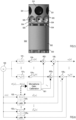
- a device 500 approximately fulfilling the requirements outlined above is shown in Figure 5 . It includes, for example, five regularly distributed broadband speakers 501 (two not visible in Figure 5 ) mounted at a cylindrical body 502 and a down-firing subwoofer 503 mounted at the bottom of the device (not visible in Figure 5 ), and eight equiangularly distributed, omnidirectional microphones 504 (five not visible in Figure 5 ), each located in the center of a cavity 505 mounted at the body 502 of the device 500.
- the distance of the layer where the speakers 501 are mounted at the cylindrical body 502, and the layer at which the microphones 504 are mounted are in parallel, i.e. the distances of the microphones 504 to the virtual, cylindrical radiating speaker 501, are the same.
- the echo cancelling performance of an acoustic echo canceler and of potentially following stages, such as a beamformer can be further improved by introducing a self-calibrating multi-microphone arrangement which can be integrated into the acoustic echo canceler depicted in Figure 4 .
- the self-calibrating multi-microphone arrangement may include (one or) a multiple of microphones 104 1 ... 104 M , a microphone calibration block 601 and controllable gain blocks 602 1 ... 602 M .
- the controllable gain blocks 602 1 ... 602 M are connected upstream of the subtractors 106 1 ...
- the microphone calibration block may individually attenuate or amplify the single electrical microphone signal dependent on a first reference signal that may represent a predetermined reference level or one or more desired (estimated) transfer functions.
- the first reference signal may be provided by a memory block (not shown) that stores and supplies the first reference signal.
- the microphone calibration block 601 may individually, frequency dependently or independently attenuate or amplify, e.g., filter, the multiplicity of electrical microphone signals dependent on one or more second reference signals derived from one or more of the multiplicity of estimated transfer functions.
- the one or more second reference signals may represent one predetermined gain (frequency dependent or independent amplification or attenuation) or a multiplicity of predetermined gains.
- the one or more second reference signals may represent a mean of some or all of the multiplicity of estimated transfer functions or a selected one of the estimated transfer functions that serves as a reference for further adapting one, some or all of the other transfer functions to be estimated.
- a single second reference signal may represent one of the estimated transfer functions other than the estimated transfer function corresponding to an electrical microphone signal to be filtered dependent on this single second reference signal.
- Parts or all of the acoustic echo canceler circuitry may be implemented as software and firmware executed by a processor or a programmable digital circuit. It is recognized that any acoustic echo canceler circuit as disclosed herein may include any number of microprocessors, integrated circuits, memory devices (e.g., FLASH, random access memory (RAM), read only memory (ROM), electrically programmable read only memory (EPROM), electrically erasable programmable read only memory (EEPROM), or other suitable variants thereof) and software which co-act with one another to perform operation(s) disclosed herein.
- RAM random access memory
- ROM read only memory
- EPROM electrically programmable read only memory
- EEPROM electrically erasable programmable read only memory
- any acoustic echo canceler circuitry as disclosed may utilize any one or more microprocessors to execute a computer-program that is embodied in a non-transitory computer readable medium that is programmed to perform any number of the functions as disclosed.
- any controller as provided herein includes a housing and a various number of microprocessors, integrated circuits, and memory devices, (e.g., FLASH, random access memory (RAM), read only memory (ROM), electrically programmable read only memory (EPROM), and/or electrically erasable programmable read only memory (EEPROM).
- FLASH random access memory
- RAM random access memory
- ROM read only memory
- EPROM electrically programmable read only memory
- EEPROM electrically erasable programmable read only memory
Landscapes
- Engineering & Computer Science (AREA)
- Physics & Mathematics (AREA)
- Signal Processing (AREA)
- General Physics & Mathematics (AREA)
- Theoretical Computer Science (AREA)
- Computational Mathematics (AREA)
- Mathematical Analysis (AREA)
- Mathematical Optimization (AREA)
- Pure & Applied Mathematics (AREA)
- Acoustics & Sound (AREA)
- Data Mining & Analysis (AREA)
- Mathematical Physics (AREA)
- Databases & Information Systems (AREA)
- General Engineering & Computer Science (AREA)
- Computational Linguistics (AREA)
- Quality & Reliability (AREA)
- Software Systems (AREA)
- Health & Medical Sciences (AREA)
- Audiology, Speech & Language Pathology (AREA)
- Human Computer Interaction (AREA)
- Algebra (AREA)
- Multimedia (AREA)
- Cable Transmission Systems, Equalization Of Radio And Reduction Of Echo (AREA)
Claims (11)
- System zum Unterdrücken von akustischem Echo, umfassend:eine Vielzahl von Mikrofonen (1041-104M), die so konfiguriert sind, dass sie Schall aufnehmen, der von einer Schallquelle (103) erzeugt und von der Schallquelle (103) über eine Vielzahl von unbekannten Übertragungswegen (1011-101M), die eine Vielzahl von unbekannten Übertragungsfunktionen (1041-104M) aufweisen, zu der Vielzahl von Mikrofonen (1041-104M) übertragen wird, und daraus eine Vielzahl von elektrischen Mikrofonsignalen bereitstellen;eine Vielzahl von adaptiven Filtern (1021-1024), die so konfiguriert sind, dass sie die Vielzahl von unbekannten Übertragungsfunktionen mit einer Vielzahl von geschätzten Übertragungsfunktionen approximieren und eine Vielzahl von elektrischen Signalen, die repräsentativ für den von der Schallquelle (103) erzeugten Schall sind, mit der Vielzahl von geschätzten Übertragungsfunktionen filtern, um daraus eine Vielzahl von geschätzten Signalen bereitzustellen; undeinen Mikrofonkalibrierungsblock (601, 6021-602M), der so konfiguriert ist, dass er die Vielzahl von elektrischen Mikrofonsignalen abhängig von einer Vielzahl von Referenzsignalen, die aus der Vielzahl von geschätzten Übertragungsfunktionen abgeleitet werden, einzeln, frequenzabhängig oder -unabhängig abschwächt oder verstärkt, wobei die Vielzahl von Referenzsignalen eine Vielzahl von vorbestimmten Verstärkungen oder gewünschten Übertragungsfunktionen repräsentiert.
- System nach Anspruch 1, wobei der Mikrofonkalibrierungsblock (601, 6021-602M) einen Mikrofonkalibrierungssteuerblock (601) und eine Vielzahl von steuerbaren Verstärkungselementen (6021-602M) umfasst, die von dem Mikrofonkalibrierungssteuerblock (601) gesteuert werden, wobei die Vielzahl von steuerbaren Verstärkungselementen frequenzabhängige oder frequenzunabhängige Verstärkungen aufweist, mit der Vielzahl von Mikrofonen (1041-104M) nachgeschaltet verbunden ist und so konfiguriert ist, dass sie die Vielzahl von elektrischen Mikrofonsignalen unter der Steuerung des Mikrofonkalibrierungssteuerblocks (601) frequenzabhängig oder - unabhängig abschwächt oder verstärkt.
- System nach Anspruch 2, wobei der Mikrofonkalibrierungssteuerblock (601) so konfiguriert ist, dass er die frequenzabhängigen oder frequenzunabhängigen Verstärkungen der Vielzahl von steuerbaren Verstärkungselementen (6021-602M) abhängig von der Vielzahl von geschätzten Übertragungsfunktionen anpasst, sobald die Vielzahl von adaptiven Filtern (1021-102M) konvergiert ist.
- System nach Anspruch 3, wobei der Mikrofonkalibrierungssteuerblock (601) so konfiguriert ist, dass er erkennt, ob die Vielzahl von adaptiven Filtern (1021-102M) konvergiert ist, indem er auswertet, ob Leistungsmaxima von Fehlersignalen einen vorbestimmten Schwellenwert unterschreiten, wobei jedes Fehlersignal ein Differenzsignal zwischen dem jeweiligen Mikrofonsignal und dem jeweiligen geschätzten Signal ist.
- System nach Anspruch 4, wobei die Vielzahl von geschätzten Übertragungsfunktionen durch Filterkoeffizienten der Vielzahl von adaptiven Filtern (1021-102M) repräsentiert wird, wobei der Mikrofonkalibrierungssteuerblock (106) so konfiguriert ist, dass er die frequenzabhängigen oder frequenzunabhängigen Verstärkungen der Vielzahl von Verstärkungselementen (6021-602M) auf der Grundlage der Filterkoeffizienten der Vielzahl von adaptiven Filtern (1021-102M) steuert.
- System nach einem der Ansprüche 1-5, wobei die Vielzahl von gewünschten Übertragungsfunktionen Folgendes repräsentiert:einen Mittelwert einiger oder der gesamten Vielzahl von geschätzten Übertragungsfunktionen; odereine der geschätzten Übertragungsfunktionen, die von der geschätzten Übertragungsfunktion verschieden ist, die einem abzuschwächenden oder zu verstärkenden elektrischen Mikrofonsignal entspricht.
- Verfahren zum Unterdrücken von akustischem Echo, umfassend:Aufnehmen von Schall mit einer Vielzahl von Mikrofonen (1041-104M), der von einer Schallquelle (103) erzeugt und von der Schallquelle (103) über eine Vielzahl von unbekannten Übertragungswegen, die eine Vielzahl von unbekannten Übertragungsfunktionen aufweisen, zu der Vielzahl von Mikrofonen (1041-104M) übertragen wird, und Bereitstellen einer Vielzahl von elektrischen Mikrofonsignalen daraus;Approximieren der Vielzahl von unbekannten Übertragungsfunktionen mit einer Vielzahl von geschätzten Übertragungsfunktionen einer Vielzahl adaptiver Filter (1021-102M) und Filtern einer Vielzahl von elektrischen Signalen, die für den von der Schallquelle (103) erzeugten Schall repräsentativ sind, mit der Vielzahl geschätzter Übertragungsfunktionen, um daraus ein oder mehrere geschätzte Signale bereitzustellen; undeinzelnes, frequenzabhängiges oder -unabhängiges Abschwächen oder Verstärken der Vielzahl von elektrischen Mikrofonsignalen abhängig von einer Vielzahl von Referenzsignalen, die aus der Vielzahl von geschätzten Übertragungsfunktionen abgeleitet sind, wobei die Vielzahl von Referenzsignalen eine Vielzahl von vorbestimmten Verstärkungen oder gewünschten Übertragungsfunktionen repräsentiert.
- Verfahren nach Anspruch 7, ferner umfassend das Anpassen der Vielzahl von steuerbaren Verstärkungselementen (6021-602M) abhängig von der Vielzahl von geschätzten Übertragungsfunktionen, sobald die Vielzahl von adaptiven Filtern (1021-102M) konvergiert ist.
- Verfahren nach Anspruch 8, ferner umfassend Erkennen, ob die Vielzahl von adaptiven Filtern (1021-102M) konvergiert ist, durch Auswerten, ob Leistungsmaxima von Fehlersignalen einen vorbestimmten Schwellenwert unterschreiten, wobei jedes Fehlersignal ein Differenzsignal zwischen dem jeweiligen Mikrofonsignal und dem jeweiligen geschätzten Signal ist.
- Verfahren nach Anspruch 9, wobei die Vielzahl von geschätzten Übertragungsfunktionen durch Filterkoeffizienten des einen oder der mehreren adaptiven Filter (1021-102M) repräsentiert wird; und das Verfahren ferner ein Steuern der Filterkoeffizienten auf der Grundlage der Filterkoeffizienten der Vielzahl von adaptiven Filtern (1021-102M) umfasst.
- Verfahren nach einem der Ansprüche 7-10, wobei die Vielzahl von gewünschten Übertragungsfunktionen Folgendes repräsentiert:den Mittelwert einiger oder der gesamten Vielzahl von geschätzten Übertragungsfunktionen; odereine der geschätzten Übertragungsfunktionen, die von der geschätzten Übertragungsfunktion verschieden ist, die einem abzuschwächenden oder zu verstärkenden elektrischen Mikrofonsignal entspricht.
Applications Claiming Priority (2)
| Application Number | Priority Date | Filing Date | Title |
|---|---|---|---|
| EP16207450 | 2016-12-30 | ||
| PCT/EP2017/081944 WO2018121972A1 (en) | 2016-12-30 | 2017-12-08 | Acoustic echo canceling |
Publications (2)
| Publication Number | Publication Date |
|---|---|
| EP3563561A1 EP3563561A1 (de) | 2019-11-06 |
| EP3563561B1 true EP3563561B1 (de) | 2025-04-02 |
Family
ID=57777460
Family Applications (1)
| Application Number | Title | Priority Date | Filing Date |
|---|---|---|---|
| EP17808950.4A Active EP3563561B1 (de) | 2016-12-30 | 2017-12-08 | Unterdrückung von akustischem echo |
Country Status (5)
| Country | Link |
|---|---|
| US (1) | US11081124B2 (de) |
| EP (1) | EP3563561B1 (de) |
| KR (1) | KR102423744B1 (de) |
| CN (1) | CN110140346B (de) |
| WO (1) | WO2018121972A1 (de) |
Families Citing this family (7)
| Publication number | Priority date | Publication date | Assignee | Title |
|---|---|---|---|---|
| JP7187183B2 (ja) * | 2018-06-14 | 2022-12-12 | 株式会社トランストロン | エコー抑圧装置、エコー抑圧方法およびエコー抑圧プログラム |
| DE102020200785A1 (de) * | 2020-01-23 | 2021-07-29 | Robert Bosch Gesellschaft mit beschränkter Haftung | Verfahren zum Validieren einer Software |
| CN113411724B (zh) * | 2021-05-07 | 2023-03-31 | 佳禾智能科技股份有限公司 | 基于骨导耳机通话的回音消除方法、计算机程序介质、骨导耳机 |
| CN113870880B (zh) * | 2021-09-22 | 2025-06-03 | 青岛海尔科技有限公司 | 语音数据的处理方法、装置及设备 |
| KR20230049238A (ko) | 2021-10-06 | 2023-04-13 | 삼성전자주식회사 | 마이크 어레이의 이상 채널 검출 및 보상 신호 생성 방법 및 장치 |
| CN120035860A (zh) * | 2023-05-15 | 2025-05-23 | 深圳市韶音科技有限公司 | 信号处理方法及声学系统 |
| CN120712794A (zh) * | 2024-01-26 | 2025-09-26 | 北京小米移动软件有限公司 | 信号处理方法、设备及存储介质 |
Family Cites Families (24)
| Publication number | Priority date | Publication date | Assignee | Title |
|---|---|---|---|---|
| FR2729024A1 (fr) * | 1994-12-30 | 1996-07-05 | Matra Communication | Annuleur d'echo acoustique avec filtrage en sous-bandes |
| EP0843934B1 (de) * | 1996-05-31 | 2007-11-14 | Koninklijke Philips Electronics N.V. | Einrichtung zur unterdrückung einer störenden komponente eines eingangssignals |
| US6185300B1 (en) * | 1996-12-31 | 2001-02-06 | Ericsson Inc. | Echo canceler for use in communications system |
| JP3625989B2 (ja) * | 1997-05-21 | 2005-03-02 | アルパイン株式会社 | 等化システム |
| DE19814971A1 (de) * | 1998-04-03 | 1999-10-07 | Daimlerchrysler Aerospace Ag | Verfahren zur Störbefreiung eines Mikrophonsignals |
| US6563925B1 (en) * | 1999-04-07 | 2003-05-13 | Ericsson Inc. | Method and apparatus for space-time echo cancellation |
| US6628781B1 (en) * | 1999-06-03 | 2003-09-30 | Telefonaktiebolaget Lm Ericsson (Publ) | Methods and apparatus for improved sub-band adaptive filtering in echo cancellation systems |
| US6947549B2 (en) * | 2003-02-19 | 2005-09-20 | The Hong Kong Polytechnic University | Echo canceller |
| JP4297003B2 (ja) * | 2004-07-09 | 2009-07-15 | ヤマハ株式会社 | 適応ハウリングキャンセラ |
| ATE413769T1 (de) * | 2004-09-03 | 2008-11-15 | Harman Becker Automotive Sys | Sprachsignalverarbeitung für die gemeinsame adaptive reduktion von störgeräuschen und von akustischen echos |
| EP1931169A4 (de) * | 2005-09-02 | 2009-12-16 | Japan Adv Inst Science & Tech | Nachfilter für eine mikrofongruppe |
| US20090010453A1 (en) * | 2007-07-02 | 2009-01-08 | Motorola, Inc. | Intelligent gradient noise reduction system |
| US8175291B2 (en) * | 2007-12-19 | 2012-05-08 | Qualcomm Incorporated | Systems, methods, and apparatus for multi-microphone based speech enhancement |
| WO2010035657A1 (ja) * | 2008-09-26 | 2010-04-01 | 日本電気株式会社 | 信号処理方法、信号処理装置、および信号処理プログラム |
| JP4377952B1 (ja) * | 2008-11-14 | 2009-12-02 | 有限会社ケプストラム | 適応フィルタ及びこれを有するエコーキャンセラ |
| EP2221983B1 (de) * | 2009-02-20 | 2011-08-31 | Harman Becker Automotive Systems GmbH | Akustische Echokompensierung |
| KR101791444B1 (ko) * | 2010-11-29 | 2017-10-30 | 뉘앙스 커뮤니케이션즈, 인코포레이티드 | 동적 마이크로폰 신호 믹서 |
| US8934620B2 (en) * | 2011-04-01 | 2015-01-13 | Cogent Signals, Inc. | Acoustic echo cancellation for high noise and excessive double talk |
| JP5496418B2 (ja) * | 2011-05-10 | 2014-05-21 | 三菱電機株式会社 | 適応等化器、音響エコーキャンセラ装置および能動騒音制御装置 |
| CN103475980B (zh) * | 2013-07-19 | 2016-05-25 | 杭州联汇数字科技有限公司 | 一种自适应声反馈消除方法 |
| US9531433B2 (en) * | 2014-02-07 | 2016-12-27 | Analog Devices Global | Echo cancellation methodology and assembly for electroacoustic communication apparatuses |
| GB2521881B (en) * | 2014-04-02 | 2016-02-10 | Imagination Tech Ltd | Auto-tuning of non-linear processor threshold |
| JP6349899B2 (ja) * | 2014-04-14 | 2018-07-04 | ヤマハ株式会社 | 放収音装置 |
| CN104994249B (zh) * | 2015-05-19 | 2017-03-15 | 百度在线网络技术(北京)有限公司 | 声回波消除方法和装置 |
-
2017
- 2017-12-08 EP EP17808950.4A patent/EP3563561B1/de active Active
- 2017-12-08 CN CN201780080980.2A patent/CN110140346B/zh active Active
- 2017-12-08 WO PCT/EP2017/081944 patent/WO2018121972A1/en not_active Ceased
- 2017-12-08 US US16/473,591 patent/US11081124B2/en active Active
- 2017-12-08 KR KR1020197018266A patent/KR102423744B1/ko active Active
Also Published As
| Publication number | Publication date |
|---|---|
| US11081124B2 (en) | 2021-08-03 |
| KR20190098981A (ko) | 2019-08-23 |
| CN110140346B (zh) | 2021-07-27 |
| CN110140346A (zh) | 2019-08-16 |
| EP3563561A1 (de) | 2019-11-06 |
| US20200152219A1 (en) | 2020-05-14 |
| KR102423744B1 (ko) | 2022-07-21 |
| WO2018121972A1 (en) | 2018-07-05 |
Similar Documents
| Publication | Publication Date | Title |
|---|---|---|
| EP3563562B1 (de) | Unterdrückung von akustischem echo | |
| EP3563561B1 (de) | Unterdrückung von akustischem echo | |
| US7003099B1 (en) | Small array microphone for acoustic echo cancellation and noise suppression | |
| EP2234105B1 (de) | Hintergrundgeräuschschätzung | |
| JP4568439B2 (ja) | エコー抑圧装置 | |
| KR20190085924A (ko) | 빔 조향 | |
| US9699554B1 (en) | Adaptive signal equalization | |
| EP2675063B1 (de) | Automatische Verstärkungsregelungsschaltung mit optimierter Referenzsignalaufbereitung für eine Echounterdrückungsschaltung | |
| EP1068773A1 (de) | Vorrichtung und verfahren zur kombinierung von audiokompression und rückkopplungsunterdrückung in einem hörgerät | |
| WO2008041878A2 (en) | System and procedure of hands free speech communication using a microphone array | |
| US9712908B2 (en) | Adaptive residual feedback suppression | |
| CN1926920A (zh) | 包括自适应反馈抑制系统的助听器 | |
| US8718562B2 (en) | Processing audio signals | |
| US20120195450A1 (en) | Method for control of adaptation of feedback suppression in a hearing aid, and a hearing aid | |
| CN111354368A (zh) | 补偿处理后的音频信号的方法 | |
| KR20220157475A (ko) | 반향 잔류 억제 | |
| CN109326297B (zh) | 自适应后滤波 | |
| US20190035414A1 (en) | Adaptive post filtering | |
| KR20200112863A (ko) | 선택가능한 샘플 레이트들을 갖는 능동 잡음 소거(anc) 시스템 | |
| US8804981B2 (en) | Processing audio signals | |
| CN109308907B (zh) | 单信道降噪 | |
| EP2869600A1 (de) | Adaptive Restrückkopplungsunterdrückung | |
| JP5606731B6 (ja) | 適応型帰還利得補正 | |
| JP5606731B2 (ja) | 適応型帰還利得補正 | |
| CN119233161A (zh) | 用于听力设备的阻塞和噪声消除系统及方法 |
Legal Events
| Date | Code | Title | Description |
|---|---|---|---|
| STAA | Information on the status of an ep patent application or granted ep patent |
Free format text: STATUS: UNKNOWN |
|
| STAA | Information on the status of an ep patent application or granted ep patent |
Free format text: STATUS: THE INTERNATIONAL PUBLICATION HAS BEEN MADE |
|
| PUAI | Public reference made under article 153(3) epc to a published international application that has entered the european phase |
Free format text: ORIGINAL CODE: 0009012 |
|
| STAA | Information on the status of an ep patent application or granted ep patent |
Free format text: STATUS: REQUEST FOR EXAMINATION WAS MADE |
|
| 17P | Request for examination filed |
Effective date: 20190607 |
|
| AK | Designated contracting states |
Kind code of ref document: A1 Designated state(s): AL AT BE BG CH CY CZ DE DK EE ES FI FR GB GR HR HU IE IS IT LI LT LU LV MC MK MT NL NO PL PT RO RS SE SI SK SM TR |
|
| AX | Request for extension of the european patent |
Extension state: BA ME |
|
| DAV | Request for validation of the european patent (deleted) | ||
| DAX | Request for extension of the european patent (deleted) | ||
| STAA | Information on the status of an ep patent application or granted ep patent |
Free format text: STATUS: EXAMINATION IS IN PROGRESS |
|
| 17Q | First examination report despatched |
Effective date: 20210419 |
|
| GRAP | Despatch of communication of intention to grant a patent |
Free format text: ORIGINAL CODE: EPIDOSNIGR1 |
|
| STAA | Information on the status of an ep patent application or granted ep patent |
Free format text: STATUS: GRANT OF PATENT IS INTENDED |
|
| INTG | Intention to grant announced |
Effective date: 20241112 |
|
| GRAS | Grant fee paid |
Free format text: ORIGINAL CODE: EPIDOSNIGR3 |
|
| GRAA | (expected) grant |
Free format text: ORIGINAL CODE: 0009210 |
|
| STAA | Information on the status of an ep patent application or granted ep patent |
Free format text: STATUS: THE PATENT HAS BEEN GRANTED |
|
| AK | Designated contracting states |
Kind code of ref document: B1 Designated state(s): AL AT BE BG CH CY CZ DE DK EE ES FI FR GB GR HR HU IE IS IT LI LT LU LV MC MK MT NL NO PL PT RO RS SE SI SK SM TR |
|
| P01 | Opt-out of the competence of the unified patent court (upc) registered |
Free format text: CASE NUMBER: APP_9286/2025 Effective date: 20250225 |
|
| REG | Reference to a national code |
Ref country code: GB Ref legal event code: FG4D |
|
| REG | Reference to a national code |
Ref country code: CH Ref legal event code: EP |
|
| REG | Reference to a national code |
Ref country code: DE Ref legal event code: R096 Ref document number: 602017088718 Country of ref document: DE |
|
| REG | Reference to a national code |
Ref country code: IE Ref legal event code: FG4D |
|
| REG | Reference to a national code |
Ref country code: NL Ref legal event code: MP Effective date: 20250402 |
|
| PG25 | Lapsed in a contracting state [announced via postgrant information from national office to epo] |
Ref country code: NL Free format text: LAPSE BECAUSE OF FAILURE TO SUBMIT A TRANSLATION OF THE DESCRIPTION OR TO PAY THE FEE WITHIN THE PRESCRIBED TIME-LIMIT Effective date: 20250402 |
|
| REG | Reference to a national code |
Ref country code: AT Ref legal event code: MK05 Ref document number: 1782426 Country of ref document: AT Kind code of ref document: T Effective date: 20250402 |
|
| PG25 | Lapsed in a contracting state [announced via postgrant information from national office to epo] |
Ref country code: PT Free format text: LAPSE BECAUSE OF FAILURE TO SUBMIT A TRANSLATION OF THE DESCRIPTION OR TO PAY THE FEE WITHIN THE PRESCRIBED TIME-LIMIT Effective date: 20250804 Ref country code: ES Free format text: LAPSE BECAUSE OF FAILURE TO SUBMIT A TRANSLATION OF THE DESCRIPTION OR TO PAY THE FEE WITHIN THE PRESCRIBED TIME-LIMIT Effective date: 20250402 Ref country code: FI Free format text: LAPSE BECAUSE OF FAILURE TO SUBMIT A TRANSLATION OF THE DESCRIPTION OR TO PAY THE FEE WITHIN THE PRESCRIBED TIME-LIMIT Effective date: 20250402 |
|
| REG | Reference to a national code |
Ref country code: LT Ref legal event code: MG9D |
|
| PG25 | Lapsed in a contracting state [announced via postgrant information from national office to epo] |
Ref country code: GR Free format text: LAPSE BECAUSE OF FAILURE TO SUBMIT A TRANSLATION OF THE DESCRIPTION OR TO PAY THE FEE WITHIN THE PRESCRIBED TIME-LIMIT Effective date: 20250703 Ref country code: NO Free format text: LAPSE BECAUSE OF FAILURE TO SUBMIT A TRANSLATION OF THE DESCRIPTION OR TO PAY THE FEE WITHIN THE PRESCRIBED TIME-LIMIT Effective date: 20250702 |
|
| PG25 | Lapsed in a contracting state [announced via postgrant information from national office to epo] |
Ref country code: PL Free format text: LAPSE BECAUSE OF FAILURE TO SUBMIT A TRANSLATION OF THE DESCRIPTION OR TO PAY THE FEE WITHIN THE PRESCRIBED TIME-LIMIT Effective date: 20250402 |
|
| PG25 | Lapsed in a contracting state [announced via postgrant information from national office to epo] |
Ref country code: BG Free format text: LAPSE BECAUSE OF FAILURE TO SUBMIT A TRANSLATION OF THE DESCRIPTION OR TO PAY THE FEE WITHIN THE PRESCRIBED TIME-LIMIT Effective date: 20250402 |
|
| PG25 | Lapsed in a contracting state [announced via postgrant information from national office to epo] |
Ref country code: HR Free format text: LAPSE BECAUSE OF FAILURE TO SUBMIT A TRANSLATION OF THE DESCRIPTION OR TO PAY THE FEE WITHIN THE PRESCRIBED TIME-LIMIT Effective date: 20250402 |
|
| PG25 | Lapsed in a contracting state [announced via postgrant information from national office to epo] |
Ref country code: AT Free format text: LAPSE BECAUSE OF FAILURE TO SUBMIT A TRANSLATION OF THE DESCRIPTION OR TO PAY THE FEE WITHIN THE PRESCRIBED TIME-LIMIT Effective date: 20250402 |
|
| PG25 | Lapsed in a contracting state [announced via postgrant information from national office to epo] |
Ref country code: RS Free format text: LAPSE BECAUSE OF FAILURE TO SUBMIT A TRANSLATION OF THE DESCRIPTION OR TO PAY THE FEE WITHIN THE PRESCRIBED TIME-LIMIT Effective date: 20250702 |
|
| PG25 | Lapsed in a contracting state [announced via postgrant information from national office to epo] |
Ref country code: IS Free format text: LAPSE BECAUSE OF FAILURE TO SUBMIT A TRANSLATION OF THE DESCRIPTION OR TO PAY THE FEE WITHIN THE PRESCRIBED TIME-LIMIT Effective date: 20250802 |
|
| PG25 | Lapsed in a contracting state [announced via postgrant information from national office to epo] |
Ref country code: LV Free format text: LAPSE BECAUSE OF FAILURE TO SUBMIT A TRANSLATION OF THE DESCRIPTION OR TO PAY THE FEE WITHIN THE PRESCRIBED TIME-LIMIT Effective date: 20250402 |
|
| REG | Reference to a national code |
Ref country code: DE Ref legal event code: R097 Ref document number: 602017088718 Country of ref document: DE |
|
| PGFP | Annual fee paid to national office [announced via postgrant information from national office to epo] |
Ref country code: DE Payment date: 20251126 Year of fee payment: 9 |
|
| PGFP | Annual fee paid to national office [announced via postgrant information from national office to epo] |
Ref country code: GB Payment date: 20251119 Year of fee payment: 9 |
|
| PG25 | Lapsed in a contracting state [announced via postgrant information from national office to epo] |
Ref country code: SM Free format text: LAPSE BECAUSE OF FAILURE TO SUBMIT A TRANSLATION OF THE DESCRIPTION OR TO PAY THE FEE WITHIN THE PRESCRIBED TIME-LIMIT Effective date: 20250402 Ref country code: DK Free format text: LAPSE BECAUSE OF FAILURE TO SUBMIT A TRANSLATION OF THE DESCRIPTION OR TO PAY THE FEE WITHIN THE PRESCRIBED TIME-LIMIT Effective date: 20250402 |
|
| PG25 | Lapsed in a contracting state [announced via postgrant information from national office to epo] |
Ref country code: CZ Free format text: LAPSE BECAUSE OF FAILURE TO SUBMIT A TRANSLATION OF THE DESCRIPTION OR TO PAY THE FEE WITHIN THE PRESCRIBED TIME-LIMIT Effective date: 20250402 |
|
| PG25 | Lapsed in a contracting state [announced via postgrant information from national office to epo] |
Ref country code: EE Free format text: LAPSE BECAUSE OF FAILURE TO SUBMIT A TRANSLATION OF THE DESCRIPTION OR TO PAY THE FEE WITHIN THE PRESCRIBED TIME-LIMIT Effective date: 20250402 |
|
| PG25 | Lapsed in a contracting state [announced via postgrant information from national office to epo] |
Ref country code: SK Free format text: LAPSE BECAUSE OF FAILURE TO SUBMIT A TRANSLATION OF THE DESCRIPTION OR TO PAY THE FEE WITHIN THE PRESCRIBED TIME-LIMIT Effective date: 20250402 Ref country code: RO Free format text: LAPSE BECAUSE OF FAILURE TO SUBMIT A TRANSLATION OF THE DESCRIPTION OR TO PAY THE FEE WITHIN THE PRESCRIBED TIME-LIMIT Effective date: 20250402 |
|
| PG25 | Lapsed in a contracting state [announced via postgrant information from national office to epo] |
Ref country code: IT Free format text: LAPSE BECAUSE OF FAILURE TO SUBMIT A TRANSLATION OF THE DESCRIPTION OR TO PAY THE FEE WITHIN THE PRESCRIBED TIME-LIMIT Effective date: 20250402 |
|
| PLBE | No opposition filed within time limit |
Free format text: ORIGINAL CODE: 0009261 |
|
| STAA | Information on the status of an ep patent application or granted ep patent |
Free format text: STATUS: NO OPPOSITION FILED WITHIN TIME LIMIT |
|
| REG | Reference to a national code |
Ref country code: CH Ref legal event code: L10 Free format text: ST27 STATUS EVENT CODE: U-0-0-L10-L00 (AS PROVIDED BY THE NATIONAL OFFICE) Effective date: 20260211 |
|
| 26N | No opposition filed |
Effective date: 20260105 |