EP3563341B1 - Procédé d'analyse céphalométrique - Google Patents
Procédé d'analyse céphalométrique Download PDFInfo
- Publication number
- EP3563341B1 EP3563341B1 EP17822769.0A EP17822769A EP3563341B1 EP 3563341 B1 EP3563341 B1 EP 3563341B1 EP 17822769 A EP17822769 A EP 17822769A EP 3563341 B1 EP3563341 B1 EP 3563341B1
- Authority
- EP
- European Patent Office
- Prior art keywords
- maxillofacial
- asymmetric
- patient
- computed
- cephalometric
- Prior art date
- Legal status (The legal status is an assumption and is not a legal conclusion. Google has not performed a legal analysis and makes no representation as to the accuracy of the status listed.)
- Active
Links
- 238000000034 method Methods 0.000 title claims description 42
- 238000010990 cephalometric method Methods 0.000 title claims description 32
- 238000004458 analytical method Methods 0.000 claims description 31
- 230000001186 cumulative effect Effects 0.000 claims description 16
- 210000004513 dentition Anatomy 0.000 claims description 15
- 230000036346 tooth eruption Effects 0.000 claims description 15
- 238000004364 calculation method Methods 0.000 claims description 5
- 238000005070 sampling Methods 0.000 claims 1
- 210000000515 tooth Anatomy 0.000 description 130
- 210000004283 incisor Anatomy 0.000 description 36
- 210000001847 jaw Anatomy 0.000 description 35
- 238000007408 cone-beam computed tomography Methods 0.000 description 22
- 210000003128 head Anatomy 0.000 description 22
- 238000012545 processing Methods 0.000 description 17
- 239000013598 vector Substances 0.000 description 17
- 230000011218 segmentation Effects 0.000 description 13
- 238000004422 calculation algorithm Methods 0.000 description 12
- 238000003384 imaging method Methods 0.000 description 11
- 210000002050 maxilla Anatomy 0.000 description 10
- 238000004590 computer program Methods 0.000 description 9
- 210000004373 mandible Anatomy 0.000 description 9
- 210000003484 anatomy Anatomy 0.000 description 8
- 230000008901 benefit Effects 0.000 description 8
- 238000010586 diagram Methods 0.000 description 8
- 238000011156 evaluation Methods 0.000 description 8
- 230000007717 exclusion Effects 0.000 description 8
- 230000003340 mental effect Effects 0.000 description 8
- 230000002159 abnormal effect Effects 0.000 description 6
- 238000002591 computed tomography Methods 0.000 description 6
- 230000001815 facial effect Effects 0.000 description 6
- 230000003287 optical effect Effects 0.000 description 6
- 230000008569 process Effects 0.000 description 6
- 210000000988 bone and bone Anatomy 0.000 description 5
- 238000005259 measurement Methods 0.000 description 5
- 238000003745 diagnosis Methods 0.000 description 4
- 230000003993 interaction Effects 0.000 description 4
- 241000878128 Malleus Species 0.000 description 3
- 206010061274 Malocclusion Diseases 0.000 description 3
- 230000009471 action Effects 0.000 description 3
- 238000004891 communication Methods 0.000 description 3
- 230000001419 dependent effect Effects 0.000 description 3
- 238000009795 derivation Methods 0.000 description 3
- 210000002331 malleus Anatomy 0.000 description 3
- 230000004044 response Effects 0.000 description 3
- 210000001154 skull base Anatomy 0.000 description 3
- 230000000007 visual effect Effects 0.000 description 3
- 230000005856 abnormality Effects 0.000 description 2
- 238000012512 characterization method Methods 0.000 description 2
- 238000005094 computer simulation Methods 0.000 description 2
- 238000011161 development Methods 0.000 description 2
- 230000018109 developmental process Effects 0.000 description 2
- 238000005516 engineering process Methods 0.000 description 2
- 230000006870 function Effects 0.000 description 2
- 239000007943 implant Substances 0.000 description 2
- 238000013507 mapping Methods 0.000 description 2
- 230000005855 radiation Effects 0.000 description 2
- 238000005096 rolling process Methods 0.000 description 2
- 210000003625 skull Anatomy 0.000 description 2
- 210000004872 soft tissue Anatomy 0.000 description 2
- 239000012536 storage buffer Substances 0.000 description 2
- 230000009466 transformation Effects 0.000 description 2
- 206010044048 Tooth missing Diseases 0.000 description 1
- 230000004075 alteration Effects 0.000 description 1
- 238000013459 approach Methods 0.000 description 1
- 230000009286 beneficial effect Effects 0.000 description 1
- 230000004397 blinking Effects 0.000 description 1
- 239000000872 buffer Substances 0.000 description 1
- 230000000295 complement effect Effects 0.000 description 1
- 238000010276 construction Methods 0.000 description 1
- 238000012937 correction Methods 0.000 description 1
- 238000013499 data model Methods 0.000 description 1
- 238000013500 data storage Methods 0.000 description 1
- 238000002059 diagnostic imaging Methods 0.000 description 1
- 238000002224 dissection Methods 0.000 description 1
- 210000002454 frontal bone Anatomy 0.000 description 1
- 230000006872 improvement Effects 0.000 description 1
- 238000001727 in vivo Methods 0.000 description 1
- 230000002452 interceptive effect Effects 0.000 description 1
- 230000007774 longterm Effects 0.000 description 1
- 239000011159 matrix material Substances 0.000 description 1
- 239000000203 mixture Substances 0.000 description 1
- 238000012544 monitoring process Methods 0.000 description 1
- 210000000537 nasal bone Anatomy 0.000 description 1
- 210000000056 organ Anatomy 0.000 description 1
- 230000008520 organization Effects 0.000 description 1
- 230000002085 persistent effect Effects 0.000 description 1
- 230000000704 physical effect Effects 0.000 description 1
- 239000000047 product Substances 0.000 description 1
- 238000002601 radiography Methods 0.000 description 1
- 238000011160 research Methods 0.000 description 1
- 238000012552 review Methods 0.000 description 1
- 239000000523 sample Substances 0.000 description 1
- 210000002483 sella turcica Anatomy 0.000 description 1
- 238000004513 sizing Methods 0.000 description 1
- 239000007787 solid Substances 0.000 description 1
- 230000006641 stabilisation Effects 0.000 description 1
- 238000011105 stabilization Methods 0.000 description 1
- 239000013589 supplement Substances 0.000 description 1
- 230000002195 synergetic effect Effects 0.000 description 1
- 238000012549 training Methods 0.000 description 1
- 238000012285 ultrasound imaging Methods 0.000 description 1
- 238000012800 visualization Methods 0.000 description 1
Images


Classifications
-
- A—HUMAN NECESSITIES
- A61—MEDICAL OR VETERINARY SCIENCE; HYGIENE
- A61B—DIAGNOSIS; SURGERY; IDENTIFICATION
- A61B6/00—Apparatus or devices for radiation diagnosis; Apparatus or devices for radiation diagnosis combined with radiation therapy equipment
- A61B6/50—Apparatus or devices for radiation diagnosis; Apparatus or devices for radiation diagnosis combined with radiation therapy equipment specially adapted for specific body parts; specially adapted for specific clinical applications
- A61B6/51—Apparatus or devices for radiation diagnosis; Apparatus or devices for radiation diagnosis combined with radiation therapy equipment specially adapted for specific body parts; specially adapted for specific clinical applications for dentistry
-
- A—HUMAN NECESSITIES
- A61—MEDICAL OR VETERINARY SCIENCE; HYGIENE
- A61B—DIAGNOSIS; SURGERY; IDENTIFICATION
- A61B6/00—Apparatus or devices for radiation diagnosis; Apparatus or devices for radiation diagnosis combined with radiation therapy equipment
- A61B6/50—Apparatus or devices for radiation diagnosis; Apparatus or devices for radiation diagnosis combined with radiation therapy equipment specially adapted for specific body parts; specially adapted for specific clinical applications
- A61B6/501—Apparatus or devices for radiation diagnosis; Apparatus or devices for radiation diagnosis combined with radiation therapy equipment specially adapted for specific body parts; specially adapted for specific clinical applications for diagnosis of the head, e.g. neuroimaging or craniography
-
- G—PHYSICS
- G06—COMPUTING; CALCULATING OR COUNTING
- G06T—IMAGE DATA PROCESSING OR GENERATION, IN GENERAL
- G06T7/00—Image analysis
- G06T7/0002—Inspection of images, e.g. flaw detection
- G06T7/0012—Biomedical image inspection
-
- A—HUMAN NECESSITIES
- A61—MEDICAL OR VETERINARY SCIENCE; HYGIENE
- A61B—DIAGNOSIS; SURGERY; IDENTIFICATION
- A61B6/00—Apparatus or devices for radiation diagnosis; Apparatus or devices for radiation diagnosis combined with radiation therapy equipment
- A61B6/02—Arrangements for diagnosis sequentially in different planes; Stereoscopic radiation diagnosis
- A61B6/025—Tomosynthesis
-
- A—HUMAN NECESSITIES
- A61—MEDICAL OR VETERINARY SCIENCE; HYGIENE
- A61B—DIAGNOSIS; SURGERY; IDENTIFICATION
- A61B6/00—Apparatus or devices for radiation diagnosis; Apparatus or devices for radiation diagnosis combined with radiation therapy equipment
- A61B6/46—Arrangements for interfacing with the operator or the patient
- A61B6/461—Displaying means of special interest
- A61B6/463—Displaying means of special interest characterised by displaying multiple images or images and diagnostic data on one display
-
- A—HUMAN NECESSITIES
- A61—MEDICAL OR VETERINARY SCIENCE; HYGIENE
- A61B—DIAGNOSIS; SURGERY; IDENTIFICATION
- A61B6/00—Apparatus or devices for radiation diagnosis; Apparatus or devices for radiation diagnosis combined with radiation therapy equipment
- A61B6/52—Devices using data or image processing specially adapted for radiation diagnosis
- A61B6/5211—Devices using data or image processing specially adapted for radiation diagnosis involving processing of medical diagnostic data
- A61B6/5217—Devices using data or image processing specially adapted for radiation diagnosis involving processing of medical diagnostic data extracting a diagnostic or physiological parameter from medical diagnostic data
-
- A—HUMAN NECESSITIES
- A61—MEDICAL OR VETERINARY SCIENCE; HYGIENE
- A61B—DIAGNOSIS; SURGERY; IDENTIFICATION
- A61B6/00—Apparatus or devices for radiation diagnosis; Apparatus or devices for radiation diagnosis combined with radiation therapy equipment
- A61B6/52—Devices using data or image processing specially adapted for radiation diagnosis
- A61B6/5211—Devices using data or image processing specially adapted for radiation diagnosis involving processing of medical diagnostic data
- A61B6/5229—Devices using data or image processing specially adapted for radiation diagnosis involving processing of medical diagnostic data combining image data of a patient, e.g. combining a functional image with an anatomical image
- A61B6/5235—Devices using data or image processing specially adapted for radiation diagnosis involving processing of medical diagnostic data combining image data of a patient, e.g. combining a functional image with an anatomical image combining images from the same or different ionising radiation imaging techniques, e.g. PET and CT
-
- A—HUMAN NECESSITIES
- A61—MEDICAL OR VETERINARY SCIENCE; HYGIENE
- A61C—DENTISTRY; APPARATUS OR METHODS FOR ORAL OR DENTAL HYGIENE
- A61C19/00—Dental auxiliary appliances
- A61C19/04—Measuring instruments specially adapted for dentistry
- A61C19/05—Measuring instruments specially adapted for dentistry for determining occlusion
-
- A—HUMAN NECESSITIES
- A61—MEDICAL OR VETERINARY SCIENCE; HYGIENE
- A61C—DENTISTRY; APPARATUS OR METHODS FOR ORAL OR DENTAL HYGIENE
- A61C7/00—Orthodontics, i.e. obtaining or maintaining the desired position of teeth, e.g. by straightening, evening, regulating, separating, or by correcting malocclusions
- A61C7/002—Orthodontic computer assisted systems
-
- G—PHYSICS
- G06—COMPUTING; CALCULATING OR COUNTING
- G06T—IMAGE DATA PROCESSING OR GENERATION, IN GENERAL
- G06T2207/00—Indexing scheme for image analysis or image enhancement
- G06T2207/10—Image acquisition modality
- G06T2207/10072—Tomographic images
- G06T2207/10081—Computed x-ray tomography [CT]
-
- G—PHYSICS
- G06—COMPUTING; CALCULATING OR COUNTING
- G06T—IMAGE DATA PROCESSING OR GENERATION, IN GENERAL
- G06T2207/00—Indexing scheme for image analysis or image enhancement
- G06T2207/30—Subject of image; Context of image processing
- G06T2207/30004—Biomedical image processing
- G06T2207/30036—Dental; Teeth
Definitions
- the present invention relates generally to image processing in x-ray computed tomography and, in particular, to acquiring 3-D data for three dimensional cephalometric analysis.
- Cephalometric analysis is the study of the dental and skeletal relationships for the head and is used by dentists and orthodontists as an assessment and planning tool for improved treatment of a patient.
- Conventional cephalometric analysis identifies bony and soft tissue landmarks in 2-D cephalometric radiographs in order to diagnose facial features and abnormalities prior to treatment, or to evaluate the progress of treatment.
- a dominant abnormality that can be identified in cephalometric analysis is the anteroposterior problem of malocclusion, relating to the skeletal relationship between the maxilla and mandible.
- Malocclusion is classified based on the relative position of the maxillary first molar.
- Class I neutrocclusion
- the molar relationship is normal but other teeth may have problems such as spacing, crowding, or over- or under-eruption.
- Class II distocclusion
- the mesiobuccal cusp of the maxillary first molar rests between the first mandible molar and second premolar.
- mesiocclusion the mesiobuccal cusp of the maxillary first molar is posterior to the mesiobuccal grooves of the mandibular first molar.
- An exemplary conventional 2-D cephalometric analysis method described by Steiner in an article entitled " Cephalometrics in Clinical Practice” assesses maxilla and mandible in relation to the cranial base using angular measures.
- Steiner selects four landmarks: Nasion, Point A, Point B and Sella.
- the Nasion is the intersection of the frontal bone and two nasal bones of the skull.
- Point A is regarded as the anterior limit of the apical base of the maxilla.
- Point B is regarded as the anterior limit of the apical base of the mandible.
- the Sella is at the mid-point of the sella turcica.
- the angle SNA (from Sella to Nasion, then to Point A) is used to determine if the maxilla is positioned anteriorly or posteriorly to the cranial base; a reading of about 82 degrees is regarded as normal.
- the angle SNB (from Sella to Nasion then to Point B) is used to determine if the mandible is positioned anteriorly or posteriorly to the cranial base; a reading of about 80 degrees is regarded as normal.
- US 6 879 712 B2 entitled “System and method of digitally modeling craniofacial features for the purposes of diagnosis and treatment predictions" to Tuncay et al. , discloses a method of generating a computer model of craniofacial features.
- the three-dimensional facial features data are acquired using laser scanning and digital photographs; dental features are acquired by physically modeling the teeth.
- the models are laser scanned. Skeletal features are then obtained from radiographs.
- the data are combined into a single computer model that can be manipulated and viewed in three dimensions.
- the model also has the ability for animation between the current modeled craniofacial features and theoretical craniofacial features.
- US 2014 / 348 405 A1 discloses a method and a system for user interaction in 3-d cephalometric analysis acquiring reconstructed volume image data from a computed tomographic scan of a patient's head.
- the acquired volume image data simultaneously displays from at least a first 2-D view and a second 2-D view.
- an operator instruction positions a reference mark corresponding to the feature on either the first or the second displayed 2-D view and the reference mark displays on each of the at least first and second displayed 2-D views.
- one or more connecting lines display between two or more of the positioned reference marks.
- One or more cephalometric parameters are derived according to the positioned reference marks, the derived parameters are displayed.
- a feature of the present disclosure is interaction with an operator to identify the locations of reference marks indicative of anatomical features.
- Embodiments of the present disclosure in a synergistic manner, integrate skills of a human operator of the system with computer capabilities for feature identification. This takes advantage of human skills of creativity, use of heuristics, flexibility, and judgment, and combines these with computer advantages, such as speed of computation, capability for exhaustive and accurate processing, and reporting and data access capabilities.
- image refers to multi-dimensional image data that is composed of discrete image elements.
- the discrete image elements are picture elements, or pixels.
- the discrete image elements are volume image elements, or voxels.
- volume image is considered to be synonymous with the term "3-D image”.
- code value refers to the value that is associated with each 2-D image pixel or, correspondingly, each volume image data element or voxel in the reconstructed 3-D volume image.
- CT computed tomography
- CBCT cone-beam computed tomography
- geometric primitive relates to an open or closed shape such as a rectangle, circle, line, traced curve, or other traced pattern.
- mark and “anatomical feature” are considered to be equivalent and refer to specific features of patient anatomy as displayed.
- viewer In the context of the present disclosure, the terms “viewer”, “operator”, and “user” are considered to be equivalent and refer to the viewing practitioner or other person who views and manipulates an image, such as a dental image, on a display monitor.
- An "operator instruction” or “viewer instruction” is obtained from explicit commands entered by the viewer, such as using a computer mouse or touch screen or keyboard entry.
- highlighting for a displayed feature has its conventional meaning as is understood to those skilled in the information and image display arts. In general, highlighting uses some form of localized display enhancement to attract the attention of the viewer. Highlighting a portion of an image, such as an individual organ, bone, or structure, or a path from one chamber to the next, for example, can be achieved in any of a number of ways, including, but not limited to, annotating, displaying a nearby or overlaying symbol, outlining or tracing, display in a different color or at a markedly different intensity or gray scale value than other image or information content, blinking or animation of a portion of a display, or display at higher sharpness or contrast.
- derived parameters relates to values calculated from processing of acquired or entered data values. Derived parameters may be a scalar, a point, a line, a volume, a vector, a plane, a curve, an angular value, an image, a closed contour, an area, a length, a matrix, a tensor, or a mathematical expression.
- set refers to a non-empty set, as the concept of a collection of elements or members of a set is widely understood in elementary mathematics.
- subset unless otherwise explicitly stated, is used herein to refer to a non-empty proper subset, that is, to a subset of the larger set, having one or more members.
- a subset may comprise the complete set S.
- a "proper subset" of set S is strictly contained in set S and excludes at least one member of set S.
- a subset B can be considered to be a proper subset of set S if (i) subset B is non-empty and (ii) if B ⁇ S is also non-empty and subset B further contains only elements that are in set S and has a cardinality that is less than that of set S.
- a "plan view” or “2-D view” is a 2-dimensional (2-D) representation or projection of a 3-dimensional (3-D) object from the position of a horizontal plane through the object.
- This term is synonymous with the term “image slice” that is conventionally used to describe displaying a 2-D planar representation from within 3-D volume image data from a particular perspective.
- 2-D views of the 3-D volume data are considered to be substantially orthogonal if the corresponding planes at which the views are taken are disposed at 90 (+ / - 10) degrees from each other, or at an integer multiple n of 90 degrees from each other ( n ⁇ 90 degrees, +/- 10 degrees).
- the general term “dentition element” relates to teeth, prosthetic devices such as dentures and implants, and supporting structures for teeth and associated prosthetic device, including jaws.
- the subject matter of the present disclosure relates to digital image processing and computer vision technologies, which is understood to mean technologies that digitally process data from a digital image to recognize and thereby assign useful meaning to human-understandable objects, attributes or conditions, and then to utilize the results obtained in further processing of the digital image.
- An embodiment of the present disclosure utilizes Treil's theory in terms of the selection of 3-D anatomic feature points, parameters derived from these feature points, and the way to use these derived parameters in cephalometric analysis.
- Reference publications authored by Treil include " The Human Face as a 3D Model for Cephalometric Analysis” Jacques Treil, B, Waysenson, J. Braga and J. Castory in World Journal of Orthodontics, 2005 Supplement, Vol. 6, issue 5, pp. 33-38 ; and " 3D Tooth Modeling for Orthodontic Assessment” by J. Treil, J. Braga, J.-M. Loubes, E. Maza, J.-M. Inglese, J. Caschreib, and B. Waysenson in Seminars in Orthodontics, Vol. 15, No. 1, March 2009 ).
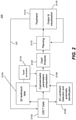
- FIG. 1 shows an imaging apparatus 100 for 3-D CBCT cephalometric imaging.
- imaging apparatus 100 For imaging a patient 12, a succession of multiple 2-D projection images is obtained and processed using imaging apparatus 100.
- a rotatable mount 130 is provided on a column 118, preferably adjustable in height to suit the size of patient 12.
- Mount 130 maintains an x-ray source 110 and a radiation sensor 121 on opposite sides of the head of patient 12 and rotates to orbit source 110 and sensor 121 in a scan pattern about the head.
- Mount 130 rotates about an axis Q that corresponds to a central portion of the patient's head, so that components attached to mount 130 orbit the head.
- Sensor 121 a digital sensor, is coupled to mount 130, opposite x-ray source 110 that emits a radiation pattern suitable for CBCT volume imaging.
- An optional head support 136 such as a chin rest or bite element, provides stabilization of the patient's head during image acquisition.
- a computer 106 has an operator interface 104 and a display 108 for accepting operator commands and for display of volume images of the orthodontia image data obtained by imaging apparatus 100.
- Computer 106 is in signal communication with sensor 121 for obtaining image data and provides signals for control of source 110 and, optionally, for control of a rotational actuator 112 for mount 130 components.
- Computer 106 is also in signal communication with a memory 132 for storing image data.
- An optional alignment apparatus 140 is provided to assist in proper alignment of the patient's head for the imaging process.
- FIG. 2 there is shown a sequence 200 of steps used for acquiring orthodontia data for 3-D cephalometric analysis with a dental CBCT volume according to an embodiment of the present disclosure.
- the CBCT volume image data is accessed in a data acquisition step S102.
- a volume contains image data for one or more 2-D images (or equivalently, slices).
- An original reconstructed CT volume is formed using standard reconstruction algorithms using multiple 2-D projections or sinograms obtained from a CT scanner.
- Figure 3 shows an exemplary dental CBCT volume 202 that contains bony anatomy, soft tissues, and teeth.
- 3-D dentition element data are collected by applying a 3-D tooth segmentation algorithm to the dental CBCT volume 202.
- Segmentation algorithms for teeth and related dentition elements are well known in the dental imaging arts. Exemplary tooth segmentation algorithms are described, for example, in commonly assigned US 2013 / 022 252 A1 entitled “PANORAMIC IMAGE GENERATION FROM CBCT DENTAL IMAGES” by Chen et al. ; in US 2013 / 022 255 A1 entitled “METHOD AND SYSTEM FOR TOOTH SEGMENTATION IN DENTAL IMAGES” by Chen et al. ; and in US 2013 / 022 254 A1 entitled “METHOD FOR TOOTH DISSECTION IN CBCT VOLUME” by Chen .
- tooth segmentation results are rendered with an image 302, wherein teeth are rendered as a whole but are segmented individually.
- Each tooth is a separate entity called a tooth volume, for example, tooth volume 304.
- Each tooth of the segmented teeth or, more broadly, each dentition element that has been segmented has, at a minimum, a 3-D position list that contains 3-D position coordinates for each of the voxels within the segmented dentition element, and a code value list of each of the voxels within the segmented element.
- the 3-D position for each of the voxels is defined with respect to the CBCT volume coordinate system.
- the CBCT volume images display with two or more different 2-D views, obtained with respect to different view angles.
- the different 2-D views can be at different angles and may be different image slices, or may be orthographic or substantially orthographic projections, or may be perspective views, for example.
- the three views are mutually orthogonal.
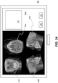
- Figure 5 shows an exemplary format with a display interface 402 showing three orthogonal 2-D views.
- an image 404 is one of the axial 2-D views of the CBCT volume image 202 ( Figure 3 )
- an image 406 is one of the coronal 2-D views of the CBCT volume image 202
- an image 408 is one of the sagittal 2-D views of the CBCT volume image 202.
- the display interface allows a viewer, such as a practitioner or technician, to interact with the computer system that executes various image processing/computer algorithms in order to accomplish a plurality of 3-D cephalometric analysis tasks.
- Viewer interaction can take any of a number of forms known to those skilled in the user interface arts, such as using a pointer such as a computer mouse joystick or touchpad, or using a touch screen for selecting an action or specifying a coordinate of the image, for interaction described in more detail subsequently.
- a pointer such as a computer mouse joystick or touchpad
- a touch screen for selecting an action or specifying a coordinate of the image, for interaction described in more detail subsequently.
- One of the 3-D cephalometric analysis tasks is to perform automatic identification in 3-D reference mark selection step S106 of Figure 2 .
- the 3-D reference marks equivalent to a type of 3-D landmark or feature point identified by the viewer on the displayed image, are shown in the different mutually orthogonal 2-D views of display interface 402 in Figure 5 .
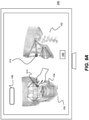
- Exemplary 3-D anatomic reference marks shown in Figure 5 are lower nasal palatine foramen at reference mark 414.
- other anatomic reference marks that can be indicated by the viewer on a displayed image 502 include infraorbital foramina at reference marks 508 and 510, and malleus at reference marks 504 and 506.
- step S106 of Figure 2 the viewer uses a pointing device (such as a mouse or touch screen, for example) to place a reference mark as a type of geometric primitive at an appropriate position in any one of the three views.
- a pointing device such as a mouse or touch screen, for example
- the reference mark displays as a circle.
- the viewer places a small circle in the view shown as image 404 at location 414 as the reference mark for a reference point.
- Reference mark 414 displays as a small circle in image 404 as well as at the proper position in corresponding views in images 406 and 408.
- the viewer need only indicate the location of the reference mark 414 in one of the displayed views 404, 406 or 408; the system responds by showing the same reference mark 414 in other views of the patient anatomy. Thus, the viewer can identify the reference mark 414 in the view in which it is most readily visible.
- the user can use operator interface tools such as the keyboard or displayed icons in order to adjust the position of the reference mark 414 on any of the displayed views.
- the viewer also has the option to remove the entered reference mark and enter a new one.
- the display interface 402 ( Figure 5 ) provides zoom in/out utilities for re-sizing any or all of the displayed views. The viewer can thus manipulate the different images efficiently for improved reference mark positioning.
- cephalometric parameters include coordinate information that is provided directly by the reference mark entry for particular features of the patient's head.
- Cephalometric parameters also include information on various measurable characteristics of the anatomy of a patient's head that are not directly entered as coordinate or geometric structures but are derived from coordinate information, termed "derived cephalometric parameters".
- Derived cephalometric parameters can provide information on relative size or volume, symmetry, orientation, shape, movement paths and possible range of movement, axes of inertia, center of mass, and other data.
- cephalometric parameters applies to those that are either directly identified, such as by the reference marks, or those derived cephalometric parameters that are computed according to the reference marks.
- framework connecting lines 522 are constructed to join the reference points for a suitable characterization of overall features, as is more clearly shown in Figure 6 .
- Framework connecting lines 522 can be considered as vectors in 3-D space; their dimensional and spatial characteristics provide additional volume image data that can be used in computation for orthodontia and other purposes.
- Each reference mark 414, 504, 506, 508, 510 is the terminal point for one or more framework connecting lines 522, generated automatically within the volume data by computer 106 of image processing apparatus 100 and forming a framework that facilitates subsequent analysis and measurement processing.
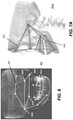
- Figures 7A , 7B, and 7C show, for displayed 3-D images 502a, 502b, and 502c from different perspective views, how a framework 520 of selected reference points, with the reference points at the vertices, helps to define dimensional aspects of the overall head structure.
- an operator instruction allows the operator to toggle between 2-D views similar to those shown in Figure 5 and the volume representation shown in Figure 6 , with partial transparency for voxels of the patient's head.
- the operator can type in more precise coordinates for a specific reference mark.
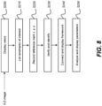
- a display step S200 displays one or more 2-D views, from different angles, such as from mutually orthogonal angles, for example, of reconstructed 3-D image data from a computed tomographic scan of a patient's head.
- the system provides a text listing such as a tabular list, a series of prompts, or a succession of labeled fields for numeric entry that requires entry of positional data for a number of landmarks or anatomical features in the reconstructed 3-D image. This listing may be explicitly provided for the operator in the form of user interface prompts or menu selection, as described subsequently.
- the listing may be implicitly defined, so that the operator need not follow a specific sequence for entering positional information.
- Reference marks that give the x, y, z positional data for different anatomical features are entered in a recording step S220.
- Anatomical features can lie within or outside of the mouth of the patient.
- Embodiments of the present disclosure can use a combination of anatomical features identified on the display, as entered in step S220, and segmentation data automatically generated for teeth and other dentition elements, as noted previously with reference to Figure 2 .
- the system accepts operator instructions that position a reference mark corresponding to each landmark feature of the anatomy.
- the reference mark is entered by the operator on either the first or the second 2-D view, or on any of the other views if more than two views are presented and, following entry, displays on each of the displayed views.
- An identification step S230 identifies the anatomical feature or landmark that corresponds to the entered reference mark and, optionally, verifies the accuracy of the operator entry. Proportional values are calculated to determine the likelihood that a given operator entry accurately identifies the position of a reference mark for a particular anatomical feature. For example, the infraorbital foramen is typically within a certain distance range from the palatine foramen; the system checks the entered distance and notifies the operator if the corresponding reference mark does not appear to be properly positioned.
- a construction step S240 framework connecting lines are generated to connect reference marks for frame generation.
- a computation and display step S250 is then executed, computing one or more cephalometric parameters according to the positioned reference marks. The computed parameters are then displayed to the operator.
- Figures 9A , 9B , and 9C show an operator interface appearing on display 108.
- the operator interface provides, on display 108, an interactive utility for accepting operator instructions and for displaying computation results for cephalometric parameters of a particular patient.
- Display 108 can be a touch screen display for entry of operator-specified reference marks and other instructions, for example.
- Display 108 simultaneously displays at least one 2-D view of the volume image data or two or more 2-D views of the volume image data from different angles or perspectives.
- Figure 9A shows a frontal or coronal view 150 paired with a side or sagittal view 152. More than two views can be shown simultaneously and different 2-D views can be shown, with each of the displayed views independently positioned according to an embodiment of the present disclosure.
- Views can be mutually orthogonal or may simply be from different angles.
- an optional control 166 enables the viewer to adjust the perspective angle from which one or more of the 2-D views are obtained, either by toggling between alternate fixed views or by changing the relative perspective angle in increments along any of the 3-D axes (x, y, z).
- a corresponding control 166 can be provided with each 2-D view, as shown in Figure 9-C .
- each reference mark 414 is entered by the operator using a pointer of some type, which may be a mouse or other electronic pointer or may be a touchscreen entry as shown in Figure 9A .
- an optional listing 156 is provided to either guide the operator to enter a specific reference mark according to a prompt, or to identify the operator entry, such as by selection from a drop-down menu 168 as shown in the example of Figure 9B .
- the operator can enter a value in listing 156 or may enter a value in field 158, then select the name associated with the entered value from drop-down menu 168.
- Figures 9A-9C show a framework 154 constructed between reference points. As Figure 9A shows, each entered reference mark 414 may be shown in both views 150 and 152. A selected reference mark 414 is highlighted on display 108, such as appearing in bold or in another color. A particular reference mark is selected in order to obtain or enter information about the reference mark or to perform some action, such as to shift its position, for example.
- the reference mark 414 just entered or selected by the operator is identified by selection from a listing 156.
- the operator selects the indicated reference mark 414, then makes a menu selection such as "infraorbital foramen" from menu 168.
- An optional field 158 identifies the highlighted reference mark 414. Calculations based on a model or based on standard known anatomical relationships can be used to identify reference mark 414, for example.
- Figure 9C shows an example in which the operator enters a reference mark 414 instruction that is detected by the system as incorrect or unlikely.
- An error prompt or error message 160 displays, indicating that the operator entry appears to be in error.
- the system computes a probable location for a particular landmark or anatomical feature based on a model or based on learned data, for example.
- message 160 displays, along with an optional alternate location 416.
- An override instruction 162 is displayed, along with a repositioning instruction 164 for repositioning the reference mark according to the calculated information from the system. Repositioning can be done by accepting another operator entry from the display screen or keyboard or by accepting the system-computed reference mark location, at alternate location 416 in the example of Figure 9C .
- the operator does not need to label reference marks as they are entered. Instead the display prompts the operator to indicate a specific landmark or anatomical feature on any of the displayed 2-D views and automatically labels the indicated feature. In this guided sequence, the operator responds to each system prompt by indicating the position of the corresponding reference mark for the specified landmark.
- the system determines which landmark or anatomical feature has been identified as the operator indicates a reference mark; the operator does not need to label reference marks as they are entered.
- the system computes the most likely reference mark using known information about anatomical features that have already been identified and, alternately, by computation using the dimensions of the reconstructed 3-D image itself.
- embodiments of the present disclosure provide a practical 3-D cephalometric analysis system that synergistically integrates the skills of the human operator of the system with the power of the computer in the process of 3-D cephalometric analysis.
- This takes advantage of human skills of creativity, use of heuristics, flexibility, and judgment, and combines these with computer advantages, such as speed of computation, capability for accurate and repeatable processing, reporting and data access and storage capabilities, and display flexibility.
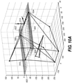
- FIGS 10A through 10E show a processing sequence for computing and analyzing cephalometric data and shows how a number of cephalometric parameters are obtained from combined volume image data and anatomical features information according to operator entered instructions and according to segmentation of the dentition elements. According to an embodiment of the present disclosure, portions of the features shown in Figures 10A through 10E are displayed on display 108 ( Figure 1 ).
- An exemplary derived cephalometric parameter shown in Figure 10A is a 3-D plane 602 (termed a t-reference plane in cephalometric analysis) that is computed by using a subset of the set of first geometric primitives with reference marks 504, 506, 508 and 510 as previously described with reference to Figure 6 .
- a further derived cephalometric parameter is 3-D coordinate reference system 612 termed a t-reference system and described by Treil in publications noted previously.
- the z axis of the t-reference system 612 is chosen as perpendicular to the 3-D t-reference plane 602.
- the y axis of the t-reference system 612 is aligned with framework connecting line 522 between reference marks 508 and 504.
- the x axis of the t-reference system 612 is in plane 602 and is orthogonal to both z and x axes of the t-reference system.
- the directions of t-reference system axes are indicated in Figure 10A and in subsequent Figures 10B , 10C , 10D , and 10E .
- the origin of the t-reference system is at the middle of framework connecting line 522 that connects reference marks 504 and 506.
- 3-D reference marks from step S106 and 3-D teeth data (3-D position list of a tooth) from step S104 are transformed from the CBCT volume coordinate system to t-reference system 612. With this transformation, subsequent computations of derived cephalometric parameters and analyses can now be performed with respect to t-reference system 612.
- a 3-D upper jaw plane 704 and a 3-D lower jaw plane 702 can be derived from cephalometric parameters from the teeth data in t-reference system 612.
- the derived upper jaw plane 704 is computed according to teeth data segmented from the upper jaw (maxilla).
- derived lower jaw plane 702 is similarly computed according to the teeth data segmented from the lower jaw (mandibular).
- an inertia tensor is formed by using the 3-D position vectors and code values of voxels of all teeth in a jaw (as described in the cited publications by Treil); eigenvectors are then computed from the inertia tensor. These eigenvectors mathematically describe the orientation of the jaw in the t-reference system 612.
- a 3-D plane can be formed using two of the eigenvectors, or using one of the eigenvectors as the plane normal.
- jaw curves are computed as derived parameters.
- An upper jaw curve 810 is computed for the upper jaw; a lower jaw curve 812 is derived for the lower jaw.
- the jaw curve is constructed to intersect with the mass center of each tooth in the respective jaw and to lie in the corresponding jaw plane. The mass center of the tooth can be calculated, in turn, using the 3-D position list and the code value list for the segmented teeth.
- the mass of a tooth is also a derived cephalometric parameter computed from the code value list of a tooth.
- an exemplary tooth mass is displayed as a circle 814 or other type of shape for an upper jaw tooth.
- one or more of the relative dimensions of the shape such as the circle radius, for example, indicates relative mass value, the mass value of the particular tooth in relation to the mass of other teeth in the jaw.
- the first molar of the upper jaw has a mass value larger than the neighboring teeth mass values.
- an eigenvector system for each tooth, is also computed.
- An inertia tensor is initially formed by using the 3-D position vectors and code values of voxels of a tooth, as described in the cited publications by Treil.
- Eigenvectors are then computed as derived cephalometric parameters from the inertia tensor. These eigenvectors mathematically describe the orientation of a tooth in the t-reference system.
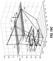
- an occlusal plane, 3-D plane 908 is computed from the two jaw planes 702 and 704.
- Occlusal plane, 3-D plane 908, lies between the two jaw planes 702 and 704.
- the normal of plane 908 is the average of the normal of plane 702 and normal of plane 704.
- the eigenvector corresponding to the largest computed eigenvalue is another derived cephalometric parameter that indicates the medial axis of the tooth.
- Figure 10E shows two types of exemplary medial axes for teeth: medial axes 1006 for upper incisors and medial axes 1004 for lower incisors.
- the calculated length of the medial axis of a tooth is a useful cephalometric parameter in cephalometric analysis and treatment planning along with other derived parameters. It should be noted that, instead of using the eigenvalue to set the length of the axis as proposed in the cited publication by Triel, embodiments of the present disclosure compute the actual medial axis length as a derived parameter using a different approach. A first intersection point of the medial axis with the bottom slice of the tooth volume is initially located. Then, a second intersection point of the medial axis with the top slice of the tooth volume is identified. An embodiment of the present disclosure then computes the length between the two intersection points.
- Figure 11 shows a graph 1102 that provides a closeup view that isolates the occlusal plane 908 in relation to upper jaw plane 704 and lower jaw plane 702 and shows the relative positions and curvature of jaw curves 810 and 812.
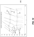
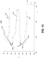
- Figure 12 shows a graph 1202 that shows the positional and angular relationships between the upper teeth medial axes 1006 and the lower teeth medial axes 1004.
- cephalometric parameters that can be derived from the combined volume image data, including dentition element segmentation, and operator-entered reference marks. These are computed in a computer-aided cephalometric analysis step S110 ( Figure 2 ).
- One exemplary 3-D cephalometric analysis procedure in step S110 that can be particularly valuable relates to the relative parallelism of the maxilla (upper jaw) and mandibular (lower jaw) planes 702 and 704. Both upper and lower jaw planes 702 and 704, respectively, are derived parameters, as noted previously.
- the assessment can be done using the following sequence:
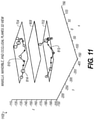
- Another exemplary 3-D cephalometric analysis procedure that is executed in step S110 is assessing the angular property between the maxilla (upper jaw) incisor and mandible (lower jaw) incisor using medial axes 1006 and 1004 ( Figures 10E , 12 ).
- the assessment can be done using the following sequence:
- Figure 13 shows a graph 1300 that shows a local x-y-z coordinate system 1302 for an upper incisor, and a local x-y-z coordinate system 1304 for a lower incisor.
- the local axes of the x-y-z coordinate system align with the eigenvectors associated with that particular tooth.
- the x axis is not shown but satisfies the right-hand system rule.
- the origin of system 1302 can be selected at any place along axis 1006.
- An exemplary origin for system 1302 is the mass center of the tooth that is associated with axis 1006.
- the origin of system 1304 can be selected at any place along axis 1004.
- An exemplary origin for system 1304 is the mass center of the tooth that is associated with axis 1004.
- An adjustment or treatment plan is arranged in a planning step S112.
- An exemplary treatment plan is to rotate the upper incisor counter clockwise at a 3-D point, such as at its local coordinate system origin, and about an arbitrary 3-D axis, such as about the x axis of the local x-y-z system.
- the graph of Figure 14 shows rotation to an axis position 1408.
- treatment is performed based on the planning, for example, based on upper incisor rotation.
- the treatment planning can be tested and verified visually in a visualization step S 116 before the actual treatment takes place.
- Step S 114 there is shown a line 120 from Step S 114 to Step S102.
- an immediate evaluation or, alternately, a scheduled evaluation of the treatment can be performed by entering relevant data as input to the system.
- relevant data for this purpose can include results from optical, radiographic, MRI, or ultrasound imaging and/or any meaningful related measurements or results.
- An optional tooth exclusion step S124 is also shown in sequence 200 of Figure 2 .
- the teeth that complement the removed teeth can be excluded.
- the operator specifies one or more teeth, if any, to be excluded from the rest of the processing steps based on Treil's theory of jaw planes parallelism.
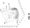
- the graph of Figure 15 shows how tooth exclusion can be learned by the system, using a virtual or digital phantom 912.
- Digital phantom 912 is a virtual model used for computation and display that is constructed using a set of landmarks and a set of upper teeth of a digital model of an upper jaw and a set of lower teeth of a digital model of a lower jaw.
- Digital phantom 912 is a 3-D or volume image data model that is representative of image data that is obtained from patient anatomy and is generated using the landmark and other anatomical information provided and can be stored for reference or may be generated for use as needed.
- the use of various types of digital phantom is well known to those skilled in the digital radiography arts.
- the landmarks such as reference marks 504, 506, 508 and 510 of the digital phantom 912 correspond to the actual reference marks identified from the CBCT volume 202 ( Figure 3 ). These landmarks are used to compute the t-reference system 612 ( Figures 10A-10E ).
- the operator can exclude one or more teeth by selecting the teeth from a display or by entering information that identifies the excluded teeth on the display.
- the upper and lower teeth such as digital teeth 2202 and 2204 of digital phantom 912 are digitally generated.
- the exemplary shape of a digital tooth is a cylinder, as shown.
- the exemplary voxel value for a digital tooth in this example is 255. It can be appreciated that other shapes and values can be used for phantom 912 representation and processing.
- Figure 16A shows digital teeth 2202 and 2204 of digital phantom 912.
- the corresponding digital teeth in the upper digital jaw and lower digital jaw are generated in a same way, with the same size and same code value.
- an inertia tensor for each digital jaw is formed by using the 3-D position vectors and code values of voxels of all digital teeth in a digital jaw (see the Treil publications, cited previously).
- Eigenvectors are then computed from the inertia tensor. These eigenvectors, as an inertial system, mathematically describe the orientation of the jaw in the t-reference system 612 ( Figure 10A ).
- the eigenvectors, computed from the inertial tensor data are one type of derived cephalometric parameter.
- Figure 16B the computed axes of an upper digital jaw inertia system 2206 and a lower digital jaw inertia system 2208 are in parallel for the generated digital phantom 912 as expected, since the upper and lower jaw teeth are created in the same way.
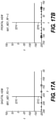
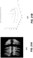
- Figure 17A shows this parallelism in the sagittal view along a line 2210 for the upper jaw and along a line 2212 for the lower jaw;
- Figure 17B shows parallelism in the frontal (coronal) view at a line 2214 for the upper jaw and at a line 2216 for the lower jaw.
- FIGS 18A and 18B there is shown a case in which digital tooth 2204 is missing.
- the computed axes of upper digital jaw inertia system 2206 and lower digital jaw inertia system 2208 are no longer in parallel.
- this misalignment can also be examined in a sagittal view along a line 2210 for the upper jaw and a line 2212 for the lower jaw; in the frontal view along a line 2214 for the upper jaw and a line 2216 for the lower jaw.
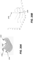
- this type of misalignment of upper and lower jaw planes (inertia system) due to one or more missing teeth can be corrected by excluding companion teeth of each missing tooth as illustrated in Figures 20A and 20B .
- the companion teeth for tooth 2204 are teeth 2304, 2302 and 2202. Tooth 2304 is the corresponding tooth in the upper jaw for tooth 2204. Teeth 2202 and 2302 are the corresponding teeth at the other side for the teeth 2304 and 2204. After excluding the companion teeth for the missing tooth 2204, the computed axes of inertia system 2206 for the upper jaw and inertia system 2208 for the lower jaw are back in parallel.
- Figures 21A and 21B illustrate segmented teeth from a CBCT volume in a case where companion teeth are excluded for a missing tooth.
- the segmentation results are shown in an image 2402.
- the computed axes of inertia systems for the upper and lower jaws are in parallel as demonstrated in a graph 2404.
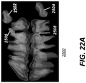
- Figures 22A and 22B show the method of exclusion of companion teeth applied to another patient using tooth exclusion step S124 ( Figure 2 ).
- teeth 2502, 2504, 2506 and 2508 are not fully developed. Their positioning, size, and orientation severely distort the physical properties of the upper jaw and lower jaw in terms of inertia system computation.
- a graph 2510 in Fig 22B depicts the situation where upper jaw inertia system 2512 and lower jaw inertia system 2514 are severely misaligned (not in parallel).
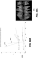
- Figures 23A and 23B show the results of excluding specific teeth from the image.
- An image 2600 shows the results of excluding teeth 2502, 2504, 2506 and 2508 from image 2500 of Figure 22A . Without the disturbance of these teeth, the axes of inertia system 2612 of the upper jaw and inertia system 2614 lower jaw of the teeth shown in image 2600 are in parallel as depicted in a graph 2610.
- step S250 for analyzing and displaying parameters generated from the recorded reference marks.
- the entered landmarks and computed inertia systems of teeth are transformed from the original CBCT image voxel space to an alternate reference system, termed the direct orthogonal landmark (DOL) reference system, with coordinates ( x d , y d , z d ).
- Figure 24 shows a number of landmarks and coordinate axes or vectors of the DOL reference system.
- Landmarks RIO and LIO indicate the infraorbital foramen; landmarks RHM and LHM mark the malleus.
- the origin o d of ( x d , y d , z d ) is selected at the middle of the line connecting landmarks RIO and LIO.
- Vector x d direction is defined from landmark RIO to LIO.
- a YZ plane is orthogonal to vector x d at point o d .
- Vector y d direction is from o ' d to o d .
- Vector z d is the cross product of x d and y d .
- Figure 26 shows, from a side view, an example with transformed inertia systems using this re-mapping.
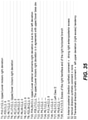
- the following listing identifies a number of individual data parameters that can be calculated and used for further analysis using the transformed landmark, dentition segmentation, and inertial system data.
- a first grouping of data parameters that can be calculated using landmarks in the transformed space gives antero-posterior values:
- the anterior-posterior category there are 9 parameters in the anterior-posterior category, 5 parameters in the vertical category and 4 parameters in the transverse category.
- Each of the above categories has three types: alveolar, basis, and architectural. Additionally, there are 8 deduced parameters that may not represent a particular spatial position or relationship but that are used in subsequent computation. These parameters can be further labeled as normal or abnormal.
- Normal parameters have a positive relationship with anterior-posterior disharmony, that is, in terms of their values: Class III ⁇ Class I ⁇ Class II. wherein Class I values indicate a normal relationship between the upper teeth, lower teeth and jaws or balanced bite; Class II values indicate that the lower first molar is posterior with respect to the upper first molar; Class III values indicate that the lower first molar is anterior with respect to the upper first molar.
- Abnormal parameters have a negative relationship with anterior-posterior disharmony, that is, in terms of their bite-related values: Class II ⁇ Class I ⁇ Class III.
- Embodiments of the present disclosure can use an analysis engine in order to compute sets of probable conditions that can be used for interpretation and as guides to treatment planning.
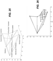
- Figures 27 - 38 show various aspects of analysis engine operation and organization and some of the text, tabular, and graphical results generated by the analysis engine.
- a computer, workstation, or host processor can be configured as an analysis engine according to a set of preprogrammed instructions that accomplish the requisite tasks and functions.
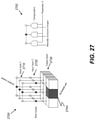
- an analysis engine can be modeled as a three-layer network 2700 as shown in Figure 27 .
- row and column node inputs can be considered to be directed to a set of comparators 2702 that provide a binary output based on the row and column input signals.
- One output cell 2704 is activated for each set of possible input conditions, as shown.
- an input layer 1 2710 is fed with one of the 26 parameters listed previously and an input layer 2 2720 is fed with another one of the 26 parameters.
- An output layer 2730 contains 9 cells each one of which represents one probable analysis if the two inputs meet certain criterion, that is, when their values are within particular ranges.
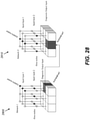
- the analysis engine has thirteen networks. These include independent networks similar to that shown in Figure 27 and coupled networks 2800 and 2810 as shown in Figure 28 .
- An algorithm shown in Figure 29 describes the operation of an independent analysis network, such as that shown in the example of Figure 27 .
- values x and y are the input parameter values; m represents the network index; D ( i,j ) is the output cell.
- the coupled network of Figure 28 combines results from two other networks and can operate as described by the algorithm in Figure 30 .
- values x and y are the input values; m represents the network index; D ( i,j ) is the output cell.
- the steps of "evaluate vector c k " for column values and "evaluate vector r k " for row values check to determine what evaluation criterion the input values meet.
- the overall arrangement of networks using the independent network model described with reference to Figure 27 or the coupled network model described with reference to Figure 28 allow analysis to examine, compare, and combine various metrics in order to provide useful results that can be reported to the practitioner and used for treatment planning.
- Figure 31A lists, for a particular patient, example parameters as numerical values and their interpretation with respect mainly to malocclusion of teeth, based on the listing of 26 parameters given previously.
- Figures 31B , 31C and 31D list, for a particular patient, example parameters as numerical values and their interpretation with respect to maxilofacial asymmetry, based on the listing of total 63 parameters given in an exemplary embodiment of this application.
- Figure 32A shows exemplary tabulated results 3200 for a particular example with bite analysis and arches angle characteristics.
- the columns indicate an underjet, normal incisors relation, or overjet condition. Rows represent occlusal classes and arches angle conditions.
- highlighting can be used to accentuate the display of information that indicates an abnormal condition or other condition of particular interest.
- analysis indicates, as a result, an underjet condition with Class III bite characteristics. This result can be used to drive treatment planning, depending on severity and practitioner judgment.
- Figure 32B shows exemplary tabulated results 3200 for another example with analysis of torque for upper and lower incisors, using parameters 3 and 4 from the listing given previously.
- Figure 32C shows exemplary tabulated results 3200 for another example with assessment of biretrusion or biprotrusion using calculated parameters given earlier as parameters (5) and (21).
- Figure 32D shows an exemplary summary listing of results for cephalometric analysis of a particular patient.
- the listing that is shown refers to analysis indications taken relative to parameters 1 - 26 listed previously.
- Figure 32E shows a detailed listing for one of the conditions reported in a tabular listing with a table 3292 with cells 3294 as shown subsequently ( Figure 35 ).
- Results information from the biometry computation can be provided for the practitioner in various different formats.
- Tabular information such as that shown in Figures 31A - 32E can be provided in file form, such as in a comma-separated value (CSV) form that is compatible for display and further calculation in tabular spreadsheet arrangement, or may be indicated in other forms, such as by providing a text message.
- CSV comma-separated value
- a graphical display such as that shown in Figure 26 , can alternately be provided as output, with particular results highlighted, such as by accentuating the intensity or color of the display for features where measured and calculated parameters show abnormal biometric relations, such as overjet, underjet, and other conditions.
- the computed biometric parameters can be used in an analysis sequence in which related parameters are processed in combination, providing results that can be compared against statistical information gathered from a patient population. The comparison can then be used to indicate abnormal relationships between various features. This relationship information can help to show how different parameters affect each other in the case of a particular patient and can provide resultant information that is used to guide treatment planning.
- memory 132 can be used to store a statistical database of cephalometric information gathered from a population of patients.
- Various items of biometric data that provides dimensional information about teeth and related supporting structures, with added information on bite, occlusion, and interrelationships of parts of the head and mouth based on this data can be stored from the patient population and analyzed.
- the analysis results can themselves be stored, providing a database of predetermined values capable of yielding a significant amount of useful information for treatment of individual patients.
- the parameter data listed in Figures 31A and 31B are computed and stored for each patient, and may be stored for a few hundred patients or for at least a statistically significant group of patients.
- the stored information includes information useful for determining ranges that are considered normal or abnormal and in need of correction. Then, in the case of an individual patient, comparison between biometric data from the patient and stored values calculated from the database can help to provide direction for an effective treatment plan.
- Figure 33 shows a system display of results 3200 with a recommendation message 170 based on analysis results and highlighting features of the patient anatomy related to the recommendation.
- Figure 34 shows a system display 108 with a graphical depiction of analysis results 3200.
- Annotated 3-D views e.g., 308a-308d are shown, arranged at different angles, along with recommendation message 170 and controls 166.
- Certain exemplary method and/or apparatus embodiments according to the present disclosure can address the need for objective metrics and displayed data that can be used to help evaluate asymmetric facial/dental anatomic structure.
- exemplary method and/or apparatus embodiments present measured and analyzed results displayed in multiple formats suitable for assessment by the practitioner.
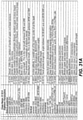
- Figure 35 shows an exemplary text report for maxillofacial asymmetry assessment according to an embodiment of the present disclosure.
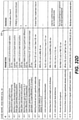
- the report lists a set of assessment tables (T1 - T19) available from the system, with cell entries (denoted by C with row and column indices, C(row, column)) providing maxillofacial/dental structural asymmetry property assessment comments organized based on the calculations related to relationships between obtained parameters, such as parameters P1-P15 in Figure 31B .
- An exemplary assessment table 3292 is depicted in Figure 32E , having four rows and four columns.
- each exemplary assessment table e.g., 19 assessment tables
- only one cell 3294 can be activated at a time; the activated cell content is highlighted, such as by being displayed in red font.
- the activated cell is C(2,2) (3294) with a content "0" indicating that asymmetry is not found for the property of incisors and molars upper/lower deviations.
- the system of the present disclosure generates a checklist type concise summary page (e.g., Figure 35 ) that provides information with respect to table numbers (Tn) , parameter numbers (Pk, j) , cell indices (Cs, t) , and actual assessment comments from assessment tables T1-T19.
- the information obtained from this type of text report can be helpful for the practitioner, providing at least some objective metrics that can be useful in developing a treatment plan for a particular patient or evaluating treatment progress.
- Further beneficial to the practitioner can be cumulative summative evaluations directed to overall condition assessments of a patient. This can be the situation, in particular, when numbers of conditional reference points and relationships therebetween utilized to determine asymmetric facial/dental anatomic structures or relationships for a patient involve large numbers of view-oriented and 3D-oriented treatment conditions, with variable underlying causes.
- 19 assessment tables can be included with hundreds of reference points and several hundreds of relationships therebetween.
- tables include: T1: Asymmetric matching incisors and molars upper/lower deviations; T2: Arch rotation; T3: Upper/lower arch right rotation and upper or lower arch responsibility; T4: Asymmetric matching incisors upper/lower deviations with upper inc transverse deviation, response of upper or lower arch in the upper/lower incisors trans deviation; T5: Asymmetric matching incisors upper/lower deviations with anterior bases transverse deviation, response of upper or lower arch anterior deviation in the upper/lower incisors trans deviation; T6: Asymmetric matching incisors upper/lower molar deviations with upper molars transverse deviation, response of upper or lower molars trans deviation; T7: Asymmetric matching incisors upper/lower molar deviations with lower molars transverse deviation; T8
- exemplary cumulative summative or overall diagnosis comments can include: Asymmetry anterior posterior direction (AP comment or S1), Asymmetry vertical direction (VT comment or S2), and Asymmetry Transverse direction (TRANS comment or S3).
- highest level evaluation score(s) can be used by using one or more or combining S1, S2 summary (e.g., overall class I, II, III), broken into few, limited, categories (e.g., normal, limited evaluation, detailed assessment suggested) or represented/characterized by dominant asymmetry condition (e.g., S1, S2, S3).
- the exemplary text report also presents S1 anterior-posterior direction "synthetic" asymmetry comment, S2 vertical direction synthetic asymmetry comment, and S3 transversal direction synthetic asymmetry comment.
- the "synthetic" terminology is derived in this application to form a pair of tables in each direction.
- the “synthetic" terminology can be determined from a combination of a plurality of tables from each assessment type (e.g., AP, V, Trans involving or representing substantial (e.g., >50%) portions of the skull) or a pair of tables in each direction.
- S1 synthetic comment is derived from Table 17 and Table 19.
- the derivation first assigns a score to each of the cells of Table 17 and Table 19.
- An exemplary score assignment is explained as follows
- S1 synthetic comment evaluates the combined score by adding the scores from Table 17 and Table 19.
- the combined score will be the summation of the scores of C(1,3) of Table 17 and C(1,1) of Table 19. Since C(1,3) in Table 17 is assigned with a value -2 and C(1,1) in Table 19 is assigned with a value -2, therefore, the combined the score is -4. Obviously, the possible combined sore values for S1 are -4, -3, -2, -1, 0, 1, 2, 3 and 4.
- selected exemplary method and/or apparatus embodiments according to the application can also provide a quick visual assessment of the asymmetry property of the maxillofacial/dental structural of a patient.
- Figure 36 is a plot or graph that shows the maxillofacial/dental structural features for a patient with respect to a front view, plotted using the landmarks, reference marks 414, selected by the operator (see Figure 5 ). This type of displayed plot clearly shows asymmetry (left vs. right) in an objective fashion for this exemplary patient.
- Figure 37 is a plot or graph of a sagittal view, with reference marks 414 showing how closely the left and right sides of a patient's face overlap, as another objective indicator of asymmetry.
- Figure 38 is a plot or graph providing a quick visual assessment of noticeable improper alignment of the bite of a patient in a sagittal view of upper and lower jaw planes 704 and 702.
- Jaw plane 704 is computed based on the derived upper jaw marks 814
- lower jaw plane 702 is computed based on the derived lower jaw marks 814.
- Derived marks 814 are computed based on the segmented teeth 304 shown in Figure 4 and show the location of the tooth.
- the example shown in Figure 38 depicts exemplary visual cues for a patient with a hyperdivergent pattern.
- Described herein is a computer-executed method for 3-D cephalometric analysis according to claim 1.
- a computer program can use stored instructions that perform 3D biometric analysis on image data that is accessed from an electronic memory.
- a computer program for operating the imaging system and probe and acquiring image data in exemplary embodiments of the application can be utilized by a suitable, general-purpose computer system operating as control logic processors as described herein, such as a personal computer or workstation.
- control logic processors as described herein
- many other types of computer systems can be used to execute the computer program of the present invention, including an arrangement of networked processors, for example.
- the computer program for performing exemplary method embodiments may be stored in a computer readable storage medium.
- This medium may include, for example; magnetic storage media such as a magnetic disk such as a hard drive or removable device or magnetic tape; optical storage media such as an optical disc, optical tape, or machine readable optical encoding; solid state electronic storage devices such as random access memory (RAM), or read only memory (ROM); or any other physical device or medium employed to store a computer program.
- Computer programs for performing exemplary method embodiments may also be stored on computer readable storage medium that is connected to the image processor by way of the internet or other network or communication medium. Those skilled in the art will further readily recognize that the equivalent of such a computer program product may also be constructed in hardware.
- memory can refer to any type of temporary or more enduring data storage workspace used for storing and operating upon image data and accessible to a computer system, including a database, for example.
- the memory could be non-volatile, using, for example, a long-term storage medium such as magnetic or optical storage. Alternately, the memory could be of a more volatile nature, using an electronic circuit, such as random-access memory (RAM) that is used as a temporary buffer or workspace by a microprocessor or other control logic processor device.
- Display data for example, is typically stored in a temporary storage buffer that is directly associated with a display device and is periodically refreshed as needed in order to provide displayed data.
- This temporary storage buffer is also considered to be a type of memory, as the term is used in the application.
- Memory is also used as the data workspace for executing and storing intermediate and final results of calculations and other processing.
- Computer-accessible memory can be volatile, non-volatile, or a hybrid combination of volatile and non-volatile types.
- Certain exemplary method and/or apparatus embodiments according to the application can allow the practitioner to take advantage of embodiments can provide multiple graduated or hierarchical measured and analyzed results displayed in successively higher order formats suitable for assessment by the practitioner.
- embodiments of the present disclosure are illustrated using dental imaging apparatus, similar principles can be applied for other types of diagnostic imaging and for other anatomy.
- Exemplary embodiments according to the application can include various features described herein (individually or in combination).
Landscapes
- Health & Medical Sciences (AREA)
- Engineering & Computer Science (AREA)
- Life Sciences & Earth Sciences (AREA)
- Medical Informatics (AREA)
- General Health & Medical Sciences (AREA)
- Veterinary Medicine (AREA)
- Public Health (AREA)
- Animal Behavior & Ethology (AREA)
- Physics & Mathematics (AREA)
- Nuclear Medicine, Radiotherapy & Molecular Imaging (AREA)
- Radiology & Medical Imaging (AREA)
- Biophysics (AREA)
- Biomedical Technology (AREA)
- Heart & Thoracic Surgery (AREA)
- Surgery (AREA)
- Molecular Biology (AREA)
- High Energy & Nuclear Physics (AREA)
- Optics & Photonics (AREA)
- Pathology (AREA)
- Dentistry (AREA)
- Oral & Maxillofacial Surgery (AREA)
- Computer Vision & Pattern Recognition (AREA)
- Epidemiology (AREA)
- General Physics & Mathematics (AREA)
- Quality & Reliability (AREA)
- Theoretical Computer Science (AREA)
- Human Computer Interaction (AREA)
- Physiology (AREA)
- General Engineering & Computer Science (AREA)
- Neurosurgery (AREA)
- Neurology (AREA)
- Apparatus For Radiation Diagnosis (AREA)
- Image Analysis (AREA)
Claims (11)
- Procédé destiné à une analyse céphalométrique 3-D d'un patient pour planifier un traitement et pour suivre les progrès d'un patient à différentes étapes d'un traitement en cours, le procédé étant exécuté au moins en partie sur un processeur informatique et comprenant :l'affichage (S102) de données d'image d'un volume reconstruit provenant d'un balayage tomographique calculé d'une tête d'un patient à partir d'au moins une première vue en 2D ou une vue en 3D ;l'acceptation (S200, S210, S220, S230, S240, S250) d'instructions d'un opérateur qui positionne et affiche au moins une marque de référence sur au moins la première vue en 2D ou la vue en 3D ;la segmentation (S104) d'un ou de plusieurs éléments de dentition dans la bouche du patient ;le calcul (S106, S108) et l'affichage d'une pluralité de paramètres céphalométriques et d'une pluralité de paramètres céphalométriques dérivés pour le patient conformément aux données provenant de ladite au moins une marque de référence et desdits un ou plusieurs éléments de dentition segmentés ;le calcul (S110), en utilisant les paramètres céphalométriques calculés, d'un ou de plusieurs résultats indicatifs d'une asymétrie maxillo-faciale ; etl'activation d'un affichage graphique ou textuel pour montrer les résultats calculés indicatifs d'une asymétrie maxillo-faciale, dans lequel l'affichage comporte :une première pluralité d'entrées représentant différentes relations antérieures postérieures d'asymétrie maxillo-faciale sélectionnées, des relations verticales d'asymétrie maxillo-faciale et des relations transversales d'asymétrie maxillo-faciale,une deuxième pluralité d'entrées représentant une condition postérieure antérieure cumulative d'asymétrie maxillo-faciale synthétisée, une condition verticale cumulative d'asymétrie maxillo-faciale synthétisée et une condition transversale cumulative d'asymétrie maxillo-faciale synthétisée, qui sont générées en utilisant la première pluralité d'entrées, etsur la base de la deuxième pluralité d'entrées, une troisième entrée représentant une combinaison de la condition postérieure antérieure cumulative d'asymétrie maxillo-faciale synthétisée, de la condition verticale cumulative d'asymétrie maxillo-faciale synthétisée et de la condition transversale cumulative d'asymétrie maxillo-faciale synthétisée.
- Procédé selon la revendication 1, dans lequel la pluralité de paramètres céphalométriques montre graphiquement une asymétrie à partir d'une vue frontale ou d'une vue sagittale.
- Procédé selon la revendication 1, comprenant en outre la comparaison des résultats calculés avec des résultats calculés précédemment et l'affichage d'un message lié à la comparaison.
- Procédé selon la revendication 1, comprenant en outre l'affichage d'une ou de plusieurs des marques de référence sur une deuxième vue en 2D qui est sensiblement orthogonale à la première vue en 2D.
- Procédé selon la revendication 1, dans lequel le calcul et l'affichage d'une pluralité de paramètres céphalométriques comprennent la génération d'un cadre tridimensionnel lié aux paramètres céphalométriques calculés.
- Procédé selon la revendication 1, dans lequel l'affichage des résultats calculés comprend l'évaluation d'un ou de plusieurs des résultats calculés par rapport à une valeur calculée à partir d'un échantillonnage d'une population de patients, et dans lequel ladite au moins une marque de référence identifie une caractéristique anatomique qui est extérieure à la bouche du patient.
- Procédé selon la revendication 1, comprenant en outre la génération et l'affichage d'un rapport tabulaire conformément à des calculs à partir des paramètres céphalométriques calculés pour chaque entrée de la première pluralité d'entrées, dans lequel ladite chaque entrée de la première pluralité d'entrées correspond à une cellule active parmi des cellules dans le rapport tabulaire lui correspondant.
- Procédé selon la revendication 1, comprenant en outre l'affichage d'un tracé graphique qui montre ladite au moins une marque de référence et les résultats calculés indicatifs de l'asymétrie maxillo-faciale.
- Procédé selon la revendication 8, dans lequel le tracé graphique affiché montre des résultats calculés provenant d'une vue sagittale, dans lequel lesdits un ou plusieurs résultats sont indicatifs d'une déviation dentaire.
- Processeur logique configuré pour planifier un traitement et pour suivre les progrès d'un patient à différentes étapes d'un traitement en cours et configuré avec des instructions codées pour :afficher des données d'image d'un volume reconstruit provenant d'un balayage tomographique calculé d'une tête d'un patient à partir d'au moins une première vue en 2D ou une vue en 3D ;accepter une instruction d'un opérateur qui positionne et affiche au moins une marque de référence sur au moins la première vue en 2D ou la vue en 3D ;segmenter un ou plusieurs éléments de dentition dans la bouche du patient ;calculer et afficher une pluralité de paramètres céphalométriques et une pluralité de paramètres céphalométriques dérivés pour le patient conformément à des données provenant d'au moins une marque de référence et desdits un ou plusieurs éléments de dentition segmentés ;calculer, en utilisant les paramètres céphalométriques calculés, un ou plusieurs résultats indicatifs d'une asymétrie maxillo-faciale ; etactiver un affichage graphique ou textuel pour montrer les résultats calculés indicatifs d'une asymétrie maxillo-faciale, dans lequel l'affichage comporte :une première pluralité d'entrées représentant différentes relations postérieures antérieures d'asymétrie maxillo-faciale sélectionnées, des relations verticales d'asymétrie maxillo-faciale et des relations transversales d'asymétrie maxillo-faciale,une deuxième pluralité d'entrées représentant une condition postérieure antérieure cumulative d'asymétrie maxillo-faciale synthétisée, une condition verticale cumulative d'asymétrie maxillo-faciale synthétisée et une condition transversale cumulative d'asymétrie maxillo-faciale synthétisée, qui sont générées en utilisant la première pluralité d'entrées, etsur la base de la deuxième pluralité d'entrées, une troisième entrée représentant une combinaison de la condition postérieure antérieure cumulative d'asymétrie maxillo-faciale synthétisée, de la condition verticale cumulative d'asymétrie maxillo-faciale synthétisée et de la condition transversale cumulative d'asymétrie maxillo-faciale synthétisée.
- Processeur logique selon la revendication 10, configuré en outre pour des paramètres céphalométriques utilisant un modèle de moteur d'analyse ayant une pluralité de réseaux.
Applications Claiming Priority (2)
| Application Number | Priority Date | Filing Date | Title |
|---|---|---|---|
| US15/395,190 US10368814B2 (en) | 2016-12-30 | 2016-12-30 | Method for cephalometric analysis |
| PCT/GB2017/053885 WO2018122553A1 (fr) | 2016-12-30 | 2017-12-22 | Procédé d'analyse céphalométrique |
Publications (2)
| Publication Number | Publication Date |
|---|---|
| EP3563341A1 EP3563341A1 (fr) | 2019-11-06 |
| EP3563341B1 true EP3563341B1 (fr) | 2022-01-26 |
Family
ID=60888544
Family Applications (1)
| Application Number | Title | Priority Date | Filing Date |
|---|---|---|---|
| EP17822769.0A Active EP3563341B1 (fr) | 2016-12-30 | 2017-12-22 | Procédé d'analyse céphalométrique |
Country Status (6)
| Country | Link |
|---|---|
| US (1) | US10368814B2 (fr) |
| EP (1) | EP3563341B1 (fr) |
| JP (2) | JP2020513918A (fr) |
| KR (1) | KR20190107683A (fr) |
| CN (1) | CN110326023B (fr) |
| WO (1) | WO2018122553A1 (fr) |
Families Citing this family (10)
| Publication number | Priority date | Publication date | Assignee | Title |
|---|---|---|---|---|
| CN108038877B (zh) * | 2017-09-01 | 2022-05-20 | 深圳市菲森科技有限公司 | 一种可视化头影测量方法、系统和计算机处理设备 |
| US10878954B2 (en) * | 2018-03-26 | 2020-12-29 | Digibrain4, Inc. | Dento-craniofacial clinical cognitive diagnosis and treatment system and method |
| KR101952887B1 (ko) * | 2018-07-27 | 2019-06-11 | 김예현 | 해부학적 랜드마크의 예측 방법 및 이를 이용한 디바이스 |
| DE102019130344A1 (de) * | 2019-11-11 | 2021-05-12 | Westfälische Wilhelms-Universität Münster | Verfahren zum Planen eines kieferchirurgischen Eingriffs bei einem Patienten |
| CN111388125B (zh) * | 2020-03-05 | 2022-03-08 | 深圳先进技术研究院 | 一种口腔正畸治疗前后牙齿移动量计算方法和装置 |
| KR102373428B1 (ko) * | 2020-03-20 | 2022-03-15 | 부산대학교 산학협력단 | 3차원 세팔로메트리를 위한 기준점 결정 방법 및 시스템 |
| US11116606B1 (en) | 2021-01-06 | 2021-09-14 | Arkimos Ltd. | Systems and methods for determining a jaw curve |
| CN113274047B (zh) * | 2021-05-18 | 2022-11-11 | 北京大学第三医院(北京大学第三临床医学院) | 一种标准化校正的咬合空间头影测量方法 |
| KR102372962B1 (ko) * | 2021-08-04 | 2022-03-11 | (주)아인사이트 | 자연 두부 위치에서 촬영된 3차원 cbct 영상에서 기계 학습 기반 치아 교정 진단을 위한 두부 계측 파라미터 도출방법 |
| CN116012436B (zh) * | 2022-12-27 | 2023-06-30 | 宁波宁兴精密制造有限公司 | 一种汽车中央通道模架对称等级分析系统 |
Citations (1)
| Publication number | Priority date | Publication date | Assignee | Title |
|---|---|---|---|---|
| US20090311647A1 (en) * | 2008-06-11 | 2009-12-17 | Jing-Jing Fang | 3d planning and prediction method for optimizing facial skeleton symmetry in orthognathic surgery |
Family Cites Families (24)
| Publication number | Priority date | Publication date | Assignee | Title |
|---|---|---|---|---|
| US6318994B1 (en) * | 1999-05-13 | 2001-11-20 | Align Technology, Inc | Tooth path treatment plan |
| US6250918B1 (en) | 1999-11-30 | 2001-06-26 | Orametrix, Inc. | Method and apparatus for simulating tooth movement for an orthodontic patient |
| AU2001255655A1 (en) * | 2000-04-25 | 2001-11-07 | Align Technology, Inc. | Treatment analysis systems and methods |
| US6879712B2 (en) | 2001-05-25 | 2005-04-12 | Orhan C. Tuncay | System and method of digitally modelling craniofacial features for the purposes of diagnosis and treatment predictions |
| GB0414277D0 (en) * | 2004-06-25 | 2004-07-28 | Leuven K U Res & Dev | Orthognatic surgery |
| US7309230B2 (en) * | 2004-12-14 | 2007-12-18 | Align Technology, Inc. | Preventing interference between tooth models |
| US7555403B2 (en) * | 2005-07-15 | 2009-06-30 | Cadent Ltd. | Method for manipulating a dental virtual model, method for creating physical entities based on a dental virtual model thus manipulated, and dental models thus created |
| ITMI20080073U1 (it) * | 2008-02-25 | 2009-08-26 | Cross Technology S R L | Distributore automatico |
| US20120041440A1 (en) * | 2009-02-04 | 2012-02-16 | Otago Innovation Limited | Intra-oral stabilisation device |
| US8979534B2 (en) * | 2009-06-17 | 2015-03-17 | The Trustees Of Columbia University In The City Of New York | Tooth scaffolds |
| EP2722818B1 (fr) * | 2009-09-04 | 2019-11-06 | Medicim NV | Procédé de numérisation d'objets dento-maxillo-facial |
| US8363919B2 (en) * | 2009-11-25 | 2013-01-29 | Imaging Sciences International Llc | Marker identification and processing in x-ray images |
| US9082177B2 (en) * | 2009-11-25 | 2015-07-14 | Dental Imaging Technologies Corporation | Method for tracking X-ray markers in serial CT projection images |
| US8805048B2 (en) * | 2010-04-01 | 2014-08-12 | Mark Batesole | Method and system for orthodontic diagnosis |
| US8849016B2 (en) | 2011-07-21 | 2014-09-30 | Carestream Health, Inc. | Panoramic image generation from CBCT dental images |
| US8929635B2 (en) | 2011-07-21 | 2015-01-06 | Carestream Health, Inc. | Method and system for tooth segmentation in dental images |
| US8842904B2 (en) | 2011-07-21 | 2014-09-23 | Carestream Health, Inc. | Method for tooth dissection in CBCT volume |
| WO2013022986A1 (fr) * | 2011-08-09 | 2013-02-14 | Optovue, Inc. | Correction de mouvement et normalisation de caractéristiques dans une tomographie par cohérence optique |
| US9305347B2 (en) * | 2013-02-13 | 2016-04-05 | Dental Imaging Technologies Corporation | Automatic volumetric image inspection |
| US9855114B2 (en) * | 2013-05-21 | 2018-01-02 | Carestream Health, Inc. | Method and system for user interaction in 3-D cephalometric analysis |
| CN104346803A (zh) * | 2013-08-05 | 2015-02-11 | 好来化工(中山)有限公司 | 用于对口腔组织进行分析的方法和装置以及牙科分析系统 |
| KR20170007309A (ko) * | 2014-05-22 | 2017-01-18 | 케어스트림 헬스 인코포레이티드 | 3-d 두부 방사선 계측 분석을 위한 방법 |
| US9675305B2 (en) * | 2014-06-03 | 2017-06-13 | Ortho-Tain | System and method for determining an orthodontic diagnostic analysis of a patient |
| CN106137414B (zh) * | 2015-04-14 | 2020-10-27 | 上海时代天使医疗器械有限公司 | 确定目标牙列布局的方法和系统 |
-
2016
- 2016-12-30 US US15/395,190 patent/US10368814B2/en active Active
-
2017
- 2017-12-22 JP JP2019535892A patent/JP2020513918A/ja active Pending
- 2017-12-22 EP EP17822769.0A patent/EP3563341B1/fr active Active
- 2017-12-22 KR KR1020197022265A patent/KR20190107683A/ko active Search and Examination
- 2017-12-22 WO PCT/GB2017/053885 patent/WO2018122553A1/fr unknown
- 2017-12-22 CN CN201780087656.3A patent/CN110326023B/zh active Active
-
2022
- 2022-12-01 JP JP2022192684A patent/JP2023014295A/ja active Pending
Patent Citations (1)
| Publication number | Priority date | Publication date | Assignee | Title |
|---|---|---|---|---|
| US20090311647A1 (en) * | 2008-06-11 | 2009-12-17 | Jing-Jing Fang | 3d planning and prediction method for optimizing facial skeleton symmetry in orthognathic surgery |
Also Published As
| Publication number | Publication date |
|---|---|
| JP2023014295A (ja) | 2023-01-26 |
| US20180184989A1 (en) | 2018-07-05 |
| CN110326023A (zh) | 2019-10-11 |
| KR20190107683A (ko) | 2019-09-20 |
| CN110326023B (zh) | 2024-04-19 |
| EP3563341A1 (fr) | 2019-11-06 |
| US10368814B2 (en) | 2019-08-06 |
| JP2020513918A (ja) | 2020-05-21 |
| WO2018122553A1 (fr) | 2018-07-05 |
Similar Documents
| Publication | Publication Date | Title |
|---|---|---|
| EP3562426B1 (fr) | Reconstruction d'un volume de tomodensitométrie virtuelle pour suivre une évolution de traitement orthodontique | |
| EP3145411B1 (fr) | Procédé d'analyse céphalométrique 3d | |
| EP3563341B1 (fr) | Procédé d'analyse céphalométrique | |
| EP3672477B1 (fr) | Verfahren und gerät zur kieferorthopädischen behandlungsplanung | |
| US10117727B2 (en) | Method and system for user interaction in 3-D cephalometric analysis | |
| EP3471617B1 (fr) | Procédé et système d'analyse céphalométrique 3d | |
| US20190197691A1 (en) | Method and system for hybrid mesh segmentation | |
| US20240099812A1 (en) | Method of optimization in orthodontic applications |
Legal Events
| Date | Code | Title | Description |
|---|---|---|---|
| STAA | Information on the status of an ep patent application or granted ep patent |
Free format text: STATUS: UNKNOWN |
|
| STAA | Information on the status of an ep patent application or granted ep patent |
Free format text: STATUS: THE INTERNATIONAL PUBLICATION HAS BEEN MADE |
|
| PUAI | Public reference made under article 153(3) epc to a published international application that has entered the european phase |
Free format text: ORIGINAL CODE: 0009012 |
|
| STAA | Information on the status of an ep patent application or granted ep patent |
Free format text: STATUS: REQUEST FOR EXAMINATION WAS MADE |
|
| 17P | Request for examination filed |
Effective date: 20190729 |
|
| AK | Designated contracting states |
Kind code of ref document: A1 Designated state(s): AL AT BE BG CH CY CZ DE DK EE ES FI FR GB GR HR HU IE IS IT LI LT LU LV MC MK MT NL NO PL PT RO RS SE SI SK SM TR |
|
| AX | Request for extension of the european patent |
Extension state: BA ME |
|
| DAV | Request for validation of the european patent (deleted) | ||
| DAX | Request for extension of the european patent (deleted) | ||
| STAA | Information on the status of an ep patent application or granted ep patent |
Free format text: STATUS: EXAMINATION IS IN PROGRESS |
|
| 17Q | First examination report despatched |
Effective date: 20200511 |
|
| STAA | Information on the status of an ep patent application or granted ep patent |
Free format text: STATUS: EXAMINATION IS IN PROGRESS |
|
| GRAP | Despatch of communication of intention to grant a patent |
Free format text: ORIGINAL CODE: EPIDOSNIGR1 |
|
| STAA | Information on the status of an ep patent application or granted ep patent |
Free format text: STATUS: GRANT OF PATENT IS INTENDED |
|
| INTG | Intention to grant announced |
Effective date: 20210719 |
|
| GRAS | Grant fee paid |
Free format text: ORIGINAL CODE: EPIDOSNIGR3 |
|
| STAA | Information on the status of an ep patent application or granted ep patent |
Free format text: STATUS: GRANT OF PATENT IS INTENDED |
|
| GRAA | (expected) grant |
Free format text: ORIGINAL CODE: 0009210 |
|
| STAA | Information on the status of an ep patent application or granted ep patent |
Free format text: STATUS: THE PATENT HAS BEEN GRANTED |
|
| AK | Designated contracting states |
Kind code of ref document: B1 Designated state(s): AL AT BE BG CH CY CZ DE DK EE ES FI FR GB GR HR HU IE IS IT LI LT LU LV MC MK MT NL NO PL PT RO RS SE SI SK SM TR |
|
| REG | Reference to a national code |
Ref country code: GB Ref legal event code: FG4D |
|
| REG | Reference to a national code |
Ref country code: CH Ref legal event code: EP |
|
| REG | Reference to a national code |
Ref country code: AT Ref legal event code: REF Ref document number: 1465867 Country of ref document: AT Kind code of ref document: T Effective date: 20220215 |
|
| REG | Reference to a national code |
Ref country code: IE Ref legal event code: FG4D |
|
| REG | Reference to a national code |
Ref country code: DE Ref legal event code: R096 Ref document number: 602017052853 Country of ref document: DE |
|
| REG | Reference to a national code |
Ref country code: LT Ref legal event code: MG9D |
|
| REG | Reference to a national code |
Ref country code: NL Ref legal event code: MP Effective date: 20220126 |
|
| REG | Reference to a national code |
Ref country code: AT Ref legal event code: MK05 Ref document number: 1465867 Country of ref document: AT Kind code of ref document: T Effective date: 20220126 |
|
| PG25 | Lapsed in a contracting state [announced via postgrant information from national office to epo] |
Ref country code: NL Free format text: LAPSE BECAUSE OF FAILURE TO SUBMIT A TRANSLATION OF THE DESCRIPTION OR TO PAY THE FEE WITHIN THE PRESCRIBED TIME-LIMIT Effective date: 20220126 |
|
| PG25 | Lapsed in a contracting state [announced via postgrant information from national office to epo] |
Ref country code: SE Free format text: LAPSE BECAUSE OF FAILURE TO SUBMIT A TRANSLATION OF THE DESCRIPTION OR TO PAY THE FEE WITHIN THE PRESCRIBED TIME-LIMIT Effective date: 20220126 Ref country code: RS Free format text: LAPSE BECAUSE OF FAILURE TO SUBMIT A TRANSLATION OF THE DESCRIPTION OR TO PAY THE FEE WITHIN THE PRESCRIBED TIME-LIMIT Effective date: 20220126 Ref country code: PT Free format text: LAPSE BECAUSE OF FAILURE TO SUBMIT A TRANSLATION OF THE DESCRIPTION OR TO PAY THE FEE WITHIN THE PRESCRIBED TIME-LIMIT Effective date: 20220526 Ref country code: NO Free format text: LAPSE BECAUSE OF FAILURE TO SUBMIT A TRANSLATION OF THE DESCRIPTION OR TO PAY THE FEE WITHIN THE PRESCRIBED TIME-LIMIT Effective date: 20220426 Ref country code: LT Free format text: LAPSE BECAUSE OF FAILURE TO SUBMIT A TRANSLATION OF THE DESCRIPTION OR TO PAY THE FEE WITHIN THE PRESCRIBED TIME-LIMIT Effective date: 20220126 Ref country code: HR Free format text: LAPSE BECAUSE OF FAILURE TO SUBMIT A TRANSLATION OF THE DESCRIPTION OR TO PAY THE FEE WITHIN THE PRESCRIBED TIME-LIMIT Effective date: 20220126 Ref country code: ES Free format text: LAPSE BECAUSE OF FAILURE TO SUBMIT A TRANSLATION OF THE DESCRIPTION OR TO PAY THE FEE WITHIN THE PRESCRIBED TIME-LIMIT Effective date: 20220126 Ref country code: BG Free format text: LAPSE BECAUSE OF FAILURE TO SUBMIT A TRANSLATION OF THE DESCRIPTION OR TO PAY THE FEE WITHIN THE PRESCRIBED TIME-LIMIT Effective date: 20220426 |
|
| PG25 | Lapsed in a contracting state [announced via postgrant information from national office to epo] |
Ref country code: PL Free format text: LAPSE BECAUSE OF FAILURE TO SUBMIT A TRANSLATION OF THE DESCRIPTION OR TO PAY THE FEE WITHIN THE PRESCRIBED TIME-LIMIT Effective date: 20220126 Ref country code: LV Free format text: LAPSE BECAUSE OF FAILURE TO SUBMIT A TRANSLATION OF THE DESCRIPTION OR TO PAY THE FEE WITHIN THE PRESCRIBED TIME-LIMIT Effective date: 20220126 Ref country code: GR Free format text: LAPSE BECAUSE OF FAILURE TO SUBMIT A TRANSLATION OF THE DESCRIPTION OR TO PAY THE FEE WITHIN THE PRESCRIBED TIME-LIMIT Effective date: 20220427 Ref country code: FI Free format text: LAPSE BECAUSE OF FAILURE TO SUBMIT A TRANSLATION OF THE DESCRIPTION OR TO PAY THE FEE WITHIN THE PRESCRIBED TIME-LIMIT Effective date: 20220126 Ref country code: AT Free format text: LAPSE BECAUSE OF FAILURE TO SUBMIT A TRANSLATION OF THE DESCRIPTION OR TO PAY THE FEE WITHIN THE PRESCRIBED TIME-LIMIT Effective date: 20220126 |
|
| PG25 | Lapsed in a contracting state [announced via postgrant information from national office to epo] |
Ref country code: IS Free format text: LAPSE BECAUSE OF FAILURE TO SUBMIT A TRANSLATION OF THE DESCRIPTION OR TO PAY THE FEE WITHIN THE PRESCRIBED TIME-LIMIT Effective date: 20220526 |
|
| REG | Reference to a national code |
Ref country code: DE Ref legal event code: R097 Ref document number: 602017052853 Country of ref document: DE |
|
| PG25 | Lapsed in a contracting state [announced via postgrant information from national office to epo] |
Ref country code: SM Free format text: LAPSE BECAUSE OF FAILURE TO SUBMIT A TRANSLATION OF THE DESCRIPTION OR TO PAY THE FEE WITHIN THE PRESCRIBED TIME-LIMIT Effective date: 20220126 Ref country code: SK Free format text: LAPSE BECAUSE OF FAILURE TO SUBMIT A TRANSLATION OF THE DESCRIPTION OR TO PAY THE FEE WITHIN THE PRESCRIBED TIME-LIMIT Effective date: 20220126 Ref country code: RO Free format text: LAPSE BECAUSE OF FAILURE TO SUBMIT A TRANSLATION OF THE DESCRIPTION OR TO PAY THE FEE WITHIN THE PRESCRIBED TIME-LIMIT Effective date: 20220126 Ref country code: EE Free format text: LAPSE BECAUSE OF FAILURE TO SUBMIT A TRANSLATION OF THE DESCRIPTION OR TO PAY THE FEE WITHIN THE PRESCRIBED TIME-LIMIT Effective date: 20220126 Ref country code: DK Free format text: LAPSE BECAUSE OF FAILURE TO SUBMIT A TRANSLATION OF THE DESCRIPTION OR TO PAY THE FEE WITHIN THE PRESCRIBED TIME-LIMIT Effective date: 20220126 Ref country code: CZ Free format text: LAPSE BECAUSE OF FAILURE TO SUBMIT A TRANSLATION OF THE DESCRIPTION OR TO PAY THE FEE WITHIN THE PRESCRIBED TIME-LIMIT Effective date: 20220126 |
|
| PG25 | Lapsed in a contracting state [announced via postgrant information from national office to epo] |
Ref country code: AL Free format text: LAPSE BECAUSE OF FAILURE TO SUBMIT A TRANSLATION OF THE DESCRIPTION OR TO PAY THE FEE WITHIN THE PRESCRIBED TIME-LIMIT Effective date: 20220126 |
|
| PLBE | No opposition filed within time limit |
Free format text: ORIGINAL CODE: 0009261 |
|
| STAA | Information on the status of an ep patent application or granted ep patent |
Free format text: STATUS: NO OPPOSITION FILED WITHIN TIME LIMIT |
|
| 26N | No opposition filed |
Effective date: 20221027 |
|
| PG25 | Lapsed in a contracting state [announced via postgrant information from national office to epo] |
Ref country code: SI Free format text: LAPSE BECAUSE OF FAILURE TO SUBMIT A TRANSLATION OF THE DESCRIPTION OR TO PAY THE FEE WITHIN THE PRESCRIBED TIME-LIMIT Effective date: 20220126 |
|
| PG25 | Lapsed in a contracting state [announced via postgrant information from national office to epo] |
Ref country code: IT Free format text: LAPSE BECAUSE OF FAILURE TO SUBMIT A TRANSLATION OF THE DESCRIPTION OR TO PAY THE FEE WITHIN THE PRESCRIBED TIME-LIMIT Effective date: 20220126 |
|
| REG | Reference to a national code |
Ref country code: CH Ref legal event code: PL |
|
| GBPC | Gb: european patent ceased through non-payment of renewal fee |
Effective date: 20221222 |
|
| REG | Reference to a national code |
Ref country code: BE Ref legal event code: MM Effective date: 20221231 |
|
| PG25 | Lapsed in a contracting state [announced via postgrant information from national office to epo] |
Ref country code: LU Free format text: LAPSE BECAUSE OF NON-PAYMENT OF DUE FEES Effective date: 20221222 |
|
| PG25 | Lapsed in a contracting state [announced via postgrant information from national office to epo] |
Ref country code: LI Free format text: LAPSE BECAUSE OF NON-PAYMENT OF DUE FEES Effective date: 20221231 Ref country code: IE Free format text: LAPSE BECAUSE OF NON-PAYMENT OF DUE FEES Effective date: 20221222 Ref country code: GB Free format text: LAPSE BECAUSE OF NON-PAYMENT OF DUE FEES Effective date: 20221222 Ref country code: CH Free format text: LAPSE BECAUSE OF NON-PAYMENT OF DUE FEES Effective date: 20221231 |
|
| PG25 | Lapsed in a contracting state [announced via postgrant information from national office to epo] |
Ref country code: BE Free format text: LAPSE BECAUSE OF NON-PAYMENT OF DUE FEES Effective date: 20221231 |
|
| PGFP | Annual fee paid to national office [announced via postgrant information from national office to epo] |
Ref country code: FR Payment date: 20231108 Year of fee payment: 7 Ref country code: DE Payment date: 20231108 Year of fee payment: 7 |
|
| PG25 | Lapsed in a contracting state [announced via postgrant information from national office to epo] |
Ref country code: HU Free format text: LAPSE BECAUSE OF FAILURE TO SUBMIT A TRANSLATION OF THE DESCRIPTION OR TO PAY THE FEE WITHIN THE PRESCRIBED TIME-LIMIT; INVALID AB INITIO Effective date: 20171222 |
|
| PG25 | Lapsed in a contracting state [announced via postgrant information from national office to epo] |
Ref country code: CY Free format text: LAPSE BECAUSE OF FAILURE TO SUBMIT A TRANSLATION OF THE DESCRIPTION OR TO PAY THE FEE WITHIN THE PRESCRIBED TIME-LIMIT Effective date: 20220126 |