EP3562633B1 - Vorrichtung zum automatischenschneiden von polystyrene - Google Patents
Vorrichtung zum automatischenschneiden von polystyrene Download PDFInfo
- Publication number
- EP3562633B1 EP3562633B1 EP16849910.1A EP16849910A EP3562633B1 EP 3562633 B1 EP3562633 B1 EP 3562633B1 EP 16849910 A EP16849910 A EP 16849910A EP 3562633 B1 EP3562633 B1 EP 3562633B1
- Authority
- EP
- European Patent Office
- Prior art keywords
- cutting
- speed
- wire
- lever element
- manner
- Prior art date
- Legal status (The legal status is an assumption and is not a legal conclusion. Google has not performed a legal analysis and makes no representation as to the accuracy of the status listed.)
- Active
Links
Images


Classifications
-
- B—PERFORMING OPERATIONS; TRANSPORTING
- B26—HAND CUTTING TOOLS; CUTTING; SEVERING
- B26F—PERFORATING; PUNCHING; CUTTING-OUT; STAMPING-OUT; SEVERING BY MEANS OTHER THAN CUTTING
- B26F3/00—Severing by means other than cutting; Apparatus therefor
- B26F3/06—Severing by using heat
- B26F3/08—Severing by using heat with heated members
- B26F3/12—Severing by using heat with heated members with heated wires
-
- B—PERFORMING OPERATIONS; TRANSPORTING
- B26—HAND CUTTING TOOLS; CUTTING; SEVERING
- B26D—CUTTING; DETAILS COMMON TO MACHINES FOR PERFORATING, PUNCHING, CUTTING-OUT, STAMPING-OUT OR SEVERING
- B26D5/00—Arrangements for operating and controlling machines or devices for cutting, cutting-out, stamping-out, punching, perforating, or severing by means other than cutting
- B26D5/20—Arrangements for operating and controlling machines or devices for cutting, cutting-out, stamping-out, punching, perforating, or severing by means other than cutting with interrelated action between the cutting member and work feed
-
- B—PERFORMING OPERATIONS; TRANSPORTING
- B26—HAND CUTTING TOOLS; CUTTING; SEVERING
- B26D—CUTTING; DETAILS COMMON TO MACHINES FOR PERFORATING, PUNCHING, CUTTING-OUT, STAMPING-OUT OR SEVERING
- B26D3/00—Cutting work characterised by the nature of the cut made; Apparatus therefor
- B26D3/006—Cutting work characterised by the nature of the cut made; Apparatus therefor specially adapted for cutting blocs of plastic material
Definitions
- the present invention refers to the technical field of equipment for cutting polystyrene.
- the invention refers to a particular equipment allowing to make cuts, according to preset geometries, that prove to be particularly precise, thus minimizing errors and waste.
- Machineries for cutting polystyrene blocks to obtain specific forms have been known for a long time.
- Polystyrene cutting by starting generally from initial blocks, allows to obtain products with various geometries, used in many fields, for example interior design, art and buildings.
- Polystyrene cutting is generally made by a metal wire which is heated to predetermined temperature through the passage of electric current, thus taking advantage of a resistive effect, named Joule effect.
- Each wire is linked at its ends to two sliders that are mobile towards one or more directions, for example along a horizontal and vertical axis or following curved or diagonal paths.
- the sliders move driven by a controlling device (generally a programmable PC or a PLC) according to a determined path.
- the controlling device through a suitable program, allows to insert the initial references, cutting geometries and measures and therefore activates and controls the engines in such a way so as to move the sliders and in such a manner as to obtain the programmed cut. Therefore, the initial block is cut into the predetermined desired shapes.
- the wire temperature and the advancement speed thereof are two variables to be necessarily coordinated, for optimizing the end product quality.
- a non-optimal temperature for example a little bit lower than required, would need a slower advancement, for allowing a correct cut by the wire. If it does not take place, a progressive bending of the wire occurs with an inaccurate cut, as its advancement is too rapid in respect to the melting speed of the material. On the contrary, a too warm wire with a too slow advancement causes an excessive local melting of polystyrene with an irregular cut, leading to product waste.
- the ideal cutting temperature and the advancement speed are parameters connected with each other and, in turn, they are conditioned by further typical features of the piece to be cut and the environmental conditions.
- polystyrene hardness kg/m3, polystyrene production, its aging and its purity are features that make each piece different from the other one. In that sense, it is not possible to standardize overall speed and temperature values for all of them, as each piece can have hardness and/or impurities that require modifications of such parameters.
- environmental parameters such as surrounding temperature and humidity level can vary time after time the behavior of the piece to be processed.
- Publication DE9100987 shows a device in which the bending condition of the support of the wire is detected as a means of detecting the force upon the wire and the temperature of the wire is varied so as to reduce that bend.
- the aim of the present invention to provide a device allowing to cut polystyrene blocks precisely, according to preset geometries, thus minimizing waste and the required time.
- Such device (20, 200) comprises means (M, S; 250, 230) configured to detect an inclination of the wire during the cutting such that a potential inclination deviation in respect to a reference inclination can be detected and consequently the advancement speed (V) can be modulated depending on the said detected deviation of inclination.
- such means comprise at least one lever element (21; 210) to which at least one hot cutting element (2) can be applied.
- the lever element is preferably assembled on suitable motorized supports, moving it according to the predetermined cutting directions.
- the lever element (21; 210) is arranged in such a manner that it can follow, in use, a possible inclination assumed by the cutting element (2), during the advancement motion of the cut.
- the wire inclination that is its bending, shows a too high advancement speed condition.
- the lever element (21; 210) is further cooperative with a sensor (M, S; 250, 230) which is able to detect one or more parameters indicating or attributable to an inclination acquired by the lever element (21; 210) during the cut.
- a sensor M, S; 250, 230
- controlling device connected to the sensor and programmed for processing the parameter/s detected by the sensor, indicating the inclination assumed by the lever element and modulating said speed consequently.
- the speed is modulated in such a manner that the lever element (21; 210) is brought back to said reference condition.
- the controlling device is programmed in such a manner so as to reduce the speed until it nullifies such detected deviation.
- the controlling device is programmed in such a manner so as to vary the speed cyclically by increasing it, once such nullifying condition of the deviation has been reached, and by reducing it again when it detects a deviation.
- said lever element (21, 210) is constrained to a support in such a manner so as to take at least one direction of inclination in respect to the constraint point (C; 220).
- said lever element is hinged.
- said sensor is a HALL sensor.
- said sensor is an infrared sensor or an ultrasonic one.
- such device can be integrated into a pre-existent machinery for cutting polystyrene.
- the device can be integrated into pre-existent machineries provided with their own controlling device which can be programmed as required.
- an assembly can be provided, with its own controlling device, to be installed always on pre-existent machineries or a machine built with such assembly can be provided.
- an assembly for cutting a polystyrene block (100) by the advancement of a hot wire at a predetermined speed (V) and characterized in that it comprises means (CL, M, S; 250, 230) configured for detecting an inclination of the wire during the cut and one controlling device (CL).
- the controlling device checks a potential inclination deviation in respect to the reference inclination and modulates the advancement speed (V) depending on said detected deviation of inclination consequently.
- At least one lever element (21, 210) to which at least one hot cutting element (2) can be applied and with the controlling device (CL) communicating with said device (20, 200).
- the lever element (21, 210) is arranged in such a manner that it can follow in use a possible inclination assumed by the cutting element (2), during the advancement motion of the cut, said lever element (21; 210) being further cooperative with a sensor (M, S; 250, 230) indicating an inclination assumed by the lever element (21; 210) while cutting, the controlling device (CL) being configured to check said potential deviation of inclination in respect to a reference inclination and to modulate consequently the advancement speed (V) of the lever element depending on said detected deviation of inclination.
- the controlling device is programmed to modulate the speed in such a manner so as to bring back the lever element (21; 210) to said reference condition.
- the said lever element (21, 210) is constrained to a support in such a manner so as to take at least one direction of inclination in respect to the constraint point (C; 220).
- lever element is hinged.
- said sensor is a HALL sensor, or, as an alternative, it can be an infrared sensor or an ultrasonic one.
- the controlling device is programmed in such a manner so as to reduce the speed until it nullifies such detected deviation.
- the controlling device is programmed in such a manner so as to vary the speed cyclically by increasing it, once such nullifying condition of the deviation has been reached, and by reducing it again when it detects a deviation.
- a method for cutting a polystyrene block (100) the method providing the arrangement of a device (20, 200) having at least one lever element (21; 210) to which at least a hot cutting element (2) can be applied and the arrangement of a controlling device (CL), said lever element (21; 210) being arranged in such a manner that a possible inclination assumed by the cutting element (2) can be followed in use, during the advancement motion of the cut, such lever element (21; 210) being further cooperative with a sensor (M, S; 250, 230) indicating possible inclination assumed by the lever element (21; 210) while cutting, the method providing the detection of the inclination of the lever element (21, 210) and the check by the controlling device (CL) of a potential variation thereof of inclination in respect to an initial reference inclination and the consequent modulation of the advancement speed (V) of the lever element depending on said detected deviation of inclination.
- the speed is modulated in such a manner so as to bring back the support to said initial reference condition.
- the speed is modulated in such a manner so as to vary the speed cyclically by increasing it, once such nullifying condition of the deviation has been reached, and by reducing it again when the deviation is detected.
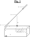
- a wire 2 is represented schematically for cutting polystyrene and it is linked at its ends with two sliders 1.
- the figure represents schematically a block 100 which, as example, is cut by the wire 2 in such a manner so as to obtain a series of tubulars with square section (3, 4, 5).
- the wire follows a cutting path represented by the dashed line and which comprises a vertical section, a second horizontal section and then the realization of tubulars placed side by side with a sequence of horizontal and vertical motions.
- this cutting pattern is only an example of many possible cutting patterns, as, depending on geometries, the motion of the wire 2 can also have different directions, such as diagonal and/or curved ones.
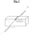
- figure 2 shows schematically an ideal and perfectly rectilinear direction 10 of the wire compared to the real curved trend (that is the bending) assumed by the wire during the cutting in this particular case.
- a solution is proposed providing the use of a sensor device (20, CL) able to detect an alignment deviation of the wire (that is inflected wire) in respect to a reference condition represented by the linearity condition of the wire (that is non-curved wire).
- the system detects a bending deviation of the wire in respect to a reference linear condition.
- Figure 3 outlines such kind of solution structurally, by outlining as a whole the device 20 comprising a sensor.
- the below described device 20 may be an element which can be mounted on pre-existing cutting machineries (that is equipped with advancement motion engine, controlling devices, etc.) or a cutting machine can be built including such integrated device.
- a lever element 21 is provided, to which a wire 2 can be connected for the cutting.
- the lever element is equipped with a sensor (M, S).
- a HALL sensor can be particularly suitable for these purposes, as it is particularly precise and sensitive.
- the sensor can be of the two-axis type (A-A; B-B) or three or more axis depending on the needs.
- This kind of sensor includes a magnet M which generates a magnetic field and an element S sensitive to such magnetic field.
- Such element S is able to detect a variation of the magnetic field when and whether the magnet modifies its position.
- the lever element 21 is hinged to a point ( C ) on a rigid support, that forms a support structure (obviously, the whole element is transportable and mountable on pre-existing machineries).
- Figure 3 shows the two axis A-A and B-B around where, for example, such lever 21 can rotate even if, obviously, the axis may be different both for number and for direction.
- the HALL sensor is provided to the opposite side of the hinging, at the opposite side to the application point of wire 2. Therefore, the figure shows the magnet M and the sensor S below, detecting the magnetic field and its variations.
- a preset quantification of such field variation, detected by the sensor can be easily linked to a certain percentage of necessary speed reduction.
- the mathematical law which links a field variation, detected by the sensor S, to the necessary speed reduction can be for example of the linear type such that a line of progressive deceleration can be easily created as a function of an increase of magnetic field deviation. Substantially, a certain deceleration can be associated to each of the detected magnetic field change delta.
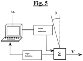
- the assembly which includes a slider provided with the sensor connected to it, is linked to the control device (CL), such as a PLC or also programmable PC computers.
- CL control device
- the element S measures the detected field and sends the detected survey to the controlling device ( CN ).
- the controlling device checks if there is a field deviation in respect to the set reference value and orders a consequent speed reduction if it finds a deviation (reduction connected to the set mathematical law depending on the detected deviation value). Therefore, such speed reduction can be proportional to the detected variation, so as to tend to progressively bring the wire in a condition of linearity, gradually while the speed is reduced.
- the cutting temperature is kept steady in a traditional way and it is not varied and it is generally set to a value immediately below the melting one or the breaking one of the used wire, in such a manner so as to take advantage of the maximum advancement speed.
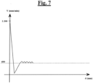
- the cutting method includes also a setting of an extremely high initial speed for any kind of polystyrene piece to be cut.
- the speed may be 2.200 mm per minute, considering that, on average, the cutting speed is approximately 600 or 700 mm per minute, or even less.
- the initial condition provides the maximum tolerable temperature for the hot wire and the maximum achievable speed.
- the wire which starts at a distance from the block, bends as soon as it meets the piece, due to the initial high speed.
- the sensor within the necessary responsiveness time, immediately detects a high field variation and the controlling device, once verified the field deviation in respect to the reference field value which represents the linearity condition of the wire, processes such difference in respect to the initial reference condition and orders a drastic speed reduction which leads the slider nearly to stop.
- the wire bending and its temperature are sufficient (for the effect of elastic returns of the wire) to keep cutting because of inertia, until the wire is in a perfectly linear condition, with a consequent return of the field value within the set reference value.
- the system is programmed in such a manner that each linearity condition of the wire is followed by a progressive speed increase. This is for guaranteeing not only the maximum efficiency, but also and specially to prevent the wire from cutting too slowly in respect to the set temperature.
- the slider starts to move with a progressively increasing speed, until it reaches its ideal equilibrium condition represented by the horizontal line set to the 600mm/min value, as an example.
- such speed is not kept constant (even if it is practicable) but it is preferred to continue varying such speed minute by minute.
- the controlling device continues to order a progressive acceleration, therefore a speed increase, until a slight axis variation of the wire is caused with a consequent new speed reduction for bringing back the wire in axis. The whole process takes place uninterruptedly during the cutting minute by minute.
- the optimal speed is as it is kept constant, but, actually, such slight variations create oscillations around an equilibrium speed and make the system adapt best to the "local" cutting condition which is operating, thus avoiding the risk of a "locally” low cutting speed in a point with a consequent cutting defect.
- the system itself automatically adapts the cutting speed minute by minute, depending on the local conditions of the area to be cut.
- infrared sensors For example, infrared sensors, ultrasound sensors or laser sensors.
- FIG. 8 An example is shown in figure 8 .
- Such figure shows an example of solution 200 with an ultrasound sensor or even a laser one.
- the lever element 210 is hinged to one of its ends (through a hinge 220) within a tubular duct 230, prearranged fixed in a support.
- the external tubular comprises two holes in axis at 90° angles and in which are respectively arranged two ultrasonic emitters 250 that project on two orthogonal axes (A-B).
- the axis B is shown as exiting from the drawing surface.
- Ultrasounds intercept the lever element 210 and are reflected backwards.
- the return period allows to calculate the position in axis or not of the lever element.
- the processor processes returning data and check if there is a position in axis or a misalignment in respect to the reference condition.
- any misalignment is easily detectable, approaching / distancing the lever element from the respective emitters and therefore, a deviation from a reference condition which represents the lever element in axis indeed.
- the controlling device reduces the speed proportionally.
- such device can be separated from any machinery and thus assembled also on pre-existing machineries.
- the device connects then to the control device (for example the PC) which is programmed for receiving from the sensor the detected data and regulating consequently the advancement speed.
- the control device for example the PC
- a further embodiment may include a detection of the wire inclination during the cutting, for example through a camera system or through a laser sensor which detects the wire and, therefore, without necessarily taking advantage of the system of lever inclination following the wire but instead by prearranging it unmovably.
- a detection of the wire inclination during the cutting for example through a camera system or through a laser sensor which detects the wire and, therefore, without necessarily taking advantage of the system of lever inclination following the wire but instead by prearranging it unmovably.
Landscapes
- Life Sciences & Earth Sciences (AREA)
- Forests & Forestry (AREA)
- Engineering & Computer Science (AREA)
- Mechanical Engineering (AREA)
- Perforating, Stamping-Out Or Severing By Means Other Than Cutting (AREA)
- Pharmaceuticals Containing Other Organic And Inorganic Compounds (AREA)
- Processing Of Stones Or Stones Resemblance Materials (AREA)
Claims (15)
- Vorrichtung (20, 200) zum Schneiden eines Polystyrolblocks (100) durch den Vorschub eines heißen Drahtes mit einer vorbestimmten Geschwindigkeit (V), dadurch gekennzeichnet, dass Mittel (M, S; 250, 230) vorgesehen und konfiguriert sind, um eine Biegung des Drahtes während des Schneidens derart zu erfassen, dass eine Biegungsabweichung in Bezug auf einen Referenzzustand verifiziert wird und die Vorschubgeschwindigkeit (V) in Abhängigkeit von dem erfassten Zustand moduliert wird.
- Vorrichtung (20, 200) nach Anspruch 1, wobei eine Steuervorrichtung (CL), beispielsweise ein Computer-PC oder eine SPS, vorgesehen und so konfiguriert ist, dass sie die Biegungsabweichung in Bezug auf den Referenzzustand verifiziert und die Vorschubgeschwindigkeit (V) in Abhängigkeit von dem erfassten Zustand moduliert.
- Vorrichtung nach Anspruch 1 oder 2, wobei Folgendes vorgesehen ist:- mindestens ein Hebelelement (21; 210), an dem mindestens ein heißer Draht (2) angebracht werden kann;- das Hebelelement (21; 210) ist so angeordnet, dass es in der Lage ist, im Gebrauch einer möglichen Neigung zu folgen, die der heiße Draht (2) während der Vorschubbewegung beim Schneiden annimmt, wobei das Hebelelement (21; 210) ferner mit einem Sensor (M, S; 250, 230) zusammenwirkt, der eine vom Hebelelement (21; 210) während des Schneidens eingenommene Neigung anzeigt, so dass eine Steuervorrichtung (CL) eine mögliche Neigungsabweichung in Bezug auf einen Referenzzustand prüfen und folglich die Vorschubgeschwindigkeit (V) des Hebelelements in Abhängigkeit von der erfassten Neigungsabweichung modulieren kann.
- Vorrichtung nach Anspruch 3, wobei die Steuervorrichtung (CL) vorgesehen und mit dem Sensor verbunden ist und so programmiert ist, dass sie den/die vom Sensor erfassten Parameter, die die vom Hebelelement während des Schneidens eingenommene Neigung anzeigen, verarbeitet und die Geschwindigkeit entsprechend moduliert.
- Vorrichtung nach Anspruch 3 oder 4, wobei die Geschwindigkeit so moduliert wird, dass das Hebelelement (21; 210) wieder in den Referenzzustand gebracht wird.
- Vorrichtung nach einem oder mehreren der vorstehenden Ansprüche 3 bis 5, wobei das Hebelelement (21, 210) so an einem Träger befestigt ist, dass es mindestens eine Neigungsrichtung in Bezug auf den Befestigungspunkt (C; 220) einnimmt, wobei das Hebelelement vorzugsweise angelenkt ist.
- Vorrichtung nach einem oder mehreren der vorstehenden Ansprüche 2 bis 4, wobei die Steuervorrichtung so programmiert ist, dass sie die Geschwindigkeit so lange reduziert, bis sie die erfasste Abweichung aufhebt.
- Vorrichtung nach einem oder mehreren der vorstehenden Ansprüche 2 bis 4 und/oder nach Anspruch 7, wobei die Steuervorrichtung so programmiert ist, dass sie die Geschwindigkeit zyklisch variiert, indem sie sie erhöht, sobald eine solche Abweichung aufgehoben wurde, und sie wieder reduziert, wenn sie eine Abweichung erfasst, die einen bestimmten voreingestellten Grenzwert überschreitet.
- Maschine zum Schneiden von Polystyrol, umfassend eine Vorrichtung nach einem oder mehreren der vorstehenden Ansprüche.
- Verfahren zum Betreiben des Schneidens eines Polystyrolblocks (100) durch den Vorschub eines heißen Drahtes mit einer vorbestimmten Geschwindigkeit (V), wobei das Verfahren die Erfassung der Biegung des Drahtes durch Mittel (M, S; 250, 230) umfasst, die zum Erfassen der Biegung des Drahtes während des Schneidens konfiguriert ist, so dass eine Biegungsabweichung des Drahtes in Bezug auf einen Referenzzustand verifiziert wird, und wobei eine daraus folgende Änderung der Vorschubgeschwindigkeit (V) des Drahtes in Abhängigkeit von dem erfassten Zustand durchgeführt wird.
- Verfahren nach Anspruch 10, wobei die Geschwindigkeit so moduliert wird, dass der Draht zurück in den Referenzzustand gebracht wird.
- Verfahren nach Anspruch 11, wobei die Geschwindigkeit so moduliert wird, dass sie zyklisch variiert wird, indem sie erhöht wird, sobald eine solche Abweichung von dem Referenzzustand aufgehoben wurde, und wieder reduziert wird, wenn die Abweichung von dem Referenzzustand erfasst wird.
- Verfahren nach Anspruch 10, wobei die Mittel (M, S, 250, 230) mindestens ein Hebelelement (21; 210) umfassen, an dem mindestens ein heißer Schneiddraht (2) angebracht ist, wobei das Hebelelement so angeordnet ist, dass es der möglichen Biegung des Drahtes während der Vorschubbewegung beim Schneiden folgt, und wobei das Hebelelement mit einem Sensor zusammenwirkt, der einen oder mehrere Parameter erfasst, die eine Biegung des Hebelelements während des Schneidens anzeigen.
- Verfahren nach einem oder mehreren der vorstehenden Ansprüche 10 bis 13, wobei der Referenzzustand der Zustand ist, in dem sich der Draht in einer geradlinigen Konfiguration befindet.
- Verfahren nach Anspruch 14, sofern abhängig von Anspruch 11, durch Verwendung einer Vorrichtung zum Schneiden, umfassend Mittel (M, S; 250, 230) zur Bestimmung einer möglichen Biegung, die der Draht während des Schneidens annimmt, und Mittel zur Modulation der Geschwindigkeit.
Applications Claiming Priority (1)
| Application Number | Priority Date | Filing Date | Title |
|---|---|---|---|
| PCT/IT2016/000308 WO2018122881A1 (en) | 2016-12-27 | 2016-12-27 | An equipment for cutting polystyrene blocks in automated way |
Publications (3)
| Publication Number | Publication Date |
|---|---|
| EP3562633A1 EP3562633A1 (de) | 2019-11-06 |
| EP3562633B1 true EP3562633B1 (de) | 2024-02-14 |
| EP3562633C0 EP3562633C0 (de) | 2024-02-14 |
Family
ID=58401934
Family Applications (1)
| Application Number | Title | Priority Date | Filing Date |
|---|---|---|---|
| EP16849910.1A Active EP3562633B1 (de) | 2016-12-27 | 2016-12-27 | Vorrichtung zum automatischenschneiden von polystyrene |
Country Status (4)
| Country | Link |
|---|---|
| US (1) | US11135737B2 (de) |
| EP (1) | EP3562633B1 (de) |
| CA (1) | CA3045057C (de) |
| WO (1) | WO2018122881A1 (de) |
Families Citing this family (3)
| Publication number | Priority date | Publication date | Assignee | Title |
|---|---|---|---|---|
| CN110891751B (zh) * | 2017-05-09 | 2022-06-14 | 维斯维什·斯里尼瓦桑 | 在cnc线切割中具有内部几何形状的切割设计方法 |
| IT201700069802A1 (it) * | 2017-06-22 | 2018-12-22 | Colines Spa | Sistema di taglio trasversale adatto ad essere usato in una macchina di produzione di film plastici |
| US11981044B2 (en) * | 2017-08-22 | 2024-05-14 | Viswesh Srinivasan | Shapeable hot scoop for material removal |
Family Cites Families (20)
| Publication number | Priority date | Publication date | Assignee | Title |
|---|---|---|---|---|
| US2972669A (en) * | 1957-10-25 | 1961-02-21 | Clyde A Brown | Materials cutting apparatus and method |
| US3635207A (en) * | 1969-12-31 | 1972-01-18 | Continental Granite Corp | Wire-type stone-cutting saw |
| US4067312A (en) * | 1976-09-08 | 1978-01-10 | Elberton Granite Association, Inc. | Automatic feedback control for wire saw |
| DE3237907A1 (de) | 1982-10-13 | 1984-05-17 | Robert 8242 Bischofswiesen Frank | Verfahren und vorrichtung zum herstellen eines surfbrettes |
| US4536145A (en) * | 1984-05-07 | 1985-08-20 | Tom Sawyer Supply & Equipment | Apparatus for forming an expanded foam form liner including a contoured surface |
| US4699032A (en) * | 1984-10-05 | 1987-10-13 | Clark Iii William T | Hot wire cutting system |
| US4601224A (en) * | 1984-10-05 | 1986-07-22 | Clark Iii William T | Hot wire cutting system |
| DE9100987U1 (de) | 1991-01-29 | 1991-04-18 | Kaehne, Robert, Dipl.-Ing., 7790 Meßkirch | Schneidegerät zum Bearbeiten thermoplastischer Schaumstoffe mit einem von elektrischem Strom durchflossenen Heizdraht |
| RU2034698C1 (ru) * | 1992-11-12 | 1995-05-10 | Исаак Маркович Френкель | Способ резания древесины и инструмент для его осуществления |
| AU708525B2 (en) * | 1994-06-16 | 1999-08-05 | Giovanni Lavermicocca | Three-dimensional puzzles |
| FR2754208B1 (fr) * | 1996-10-03 | 1998-12-11 | Esox | Dispositif pour la decoupe de pieces de forme quelconque |
| JP3104959U (ja) * | 2004-04-30 | 2004-10-21 | 慎吾 大給 | ワイヤソー加工機 |
| US7503831B2 (en) * | 2006-04-26 | 2009-03-17 | Siemens Medical Solutions Usa, Inc. | System and method for cutting soluble scintillator material |
| JP4998928B2 (ja) * | 2006-06-30 | 2012-08-15 | 国立大学法人 長崎大学 | 切断方法及び切断装置 |
| WO2010006148A2 (en) * | 2008-07-11 | 2010-01-14 | Saint-Gobain Abrasives. Inc. | Wire slicing system |
| IT1395077B1 (it) * | 2009-08-13 | 2012-09-05 | Ts R&D S R L | Macchina per il taglio di elementi strutturali, quali piloni, travi, putrelle o simili di sostegno di strutture in acciaio, calcestruzzo, acciaio e calcestruzzo, materiali litoidi o simili |
| EP2402125A1 (de) * | 2010-06-29 | 2012-01-04 | Siemens Aktiengesellschaft | Verfahren zur Herstellung von Testkomponenten mittels eines Hitzdrahtschneiders |
| JP6132438B2 (ja) * | 2014-03-19 | 2017-05-24 | コマツNtc株式会社 | シングルワイヤ式のワイヤソーによる切断方法およびシングルワイヤ式のワイヤソー |
| FR3048903B1 (fr) * | 2016-03-15 | 2018-04-13 | Saint-Gobain Placo | Procede et dispositif de decoupe d'une plaque ou d'un panneau de materiau de construction poreux |
| JP6919852B2 (ja) * | 2016-09-27 | 2021-08-18 | 株式会社テック技販 | インゴットの切断装置、および、インゴットの切断装置に使用される荷重検出装置 |
-
2016
- 2016-12-27 EP EP16849910.1A patent/EP3562633B1/de active Active
- 2016-12-27 CA CA3045057A patent/CA3045057C/en active Active
- 2016-12-27 US US16/470,592 patent/US11135737B2/en active Active
- 2016-12-27 WO PCT/IT2016/000308 patent/WO2018122881A1/en not_active Ceased
Also Published As
| Publication number | Publication date |
|---|---|
| US20190366576A1 (en) | 2019-12-05 |
| WO2018122881A8 (en) | 2019-08-08 |
| WO2018122881A1 (en) | 2018-07-05 |
| CA3045057C (en) | 2021-07-13 |
| EP3562633A1 (de) | 2019-11-06 |
| US11135737B2 (en) | 2021-10-05 |
| CA3045057A1 (en) | 2018-07-05 |
| EP3562633C0 (de) | 2024-02-14 |
Similar Documents
| Publication | Publication Date | Title |
|---|---|---|
| EP3562633B1 (de) | Vorrichtung zum automatischenschneiden von polystyrene | |
| EP1374139B1 (de) | Steuerung für einen laser mit prädiktiven modellen des bewegungssystems des laserstrahls | |
| US11256229B2 (en) | Industrial machinery and control method thereof | |
| US8073568B2 (en) | Device utilizing a PID controller, control method thereof, and robot utilizing the controller | |
| EP2261595B1 (de) | Kreisförmigkeitsmessgerät | |
| CN107407931A (zh) | 通过触碰操纵器实现的鲁棒的直观的操作方法 | |
| KR101251184B1 (ko) | 구동 명령을 이용한 비젼 트래킹 시스템 및 방법 | |
| CN107791150A (zh) | 流体射流切割系统以及控制流体射流切割头的运动的方法 | |
| EP3278892B1 (de) | Ausrüstung zum mechanischen umformen von blechen | |
| US11981044B2 (en) | Shapeable hot scoop for material removal | |
| JP2006102889A (ja) | 減速機の異常判定装置及び減速機の異常判定方法 | |
| JP2004148466A5 (de) | ||
| JP2019188548A (ja) | 数値制御装置 | |
| US6430787B1 (en) | Apparatus and method for carving and separating carpet | |
| RU2010117394A (ru) | Способ, устройство и компьютерная программа для регулировки работы гидравлической стрелы | |
| WO2022054674A1 (ja) | キサゲ加工を行うロボットシステム、方法、及びコンピュータプログラム | |
| JP6836564B2 (ja) | センサブラケットおよびロボットシステム | |
| CA2524664A1 (en) | System and method to selectively prevent movements of an electric vehicle | |
| JP2019217563A (ja) | ロボットシステムおよびロボット | |
| CN110053042B (zh) | 机器人控制装置 | |
| CN116802019B (zh) | 进行刮研加工的机器人系统、方法以及计算机程序 | |
| CN110366478A (zh) | 铰接臂机器人和借助于铰接臂机器人来切削加工工件的方法 | |
| JP7436174B2 (ja) | 工作機械 | |
| JP2015217490A (ja) | 多方向支持ガイドローラの方向制御方法および多方向支持ガイドローラの方向制御装置 | |
| CN102649381A (zh) | 材质自适应数字雕刻机 |
Legal Events
| Date | Code | Title | Description |
|---|---|---|---|
| STAA | Information on the status of an ep patent application or granted ep patent |
Free format text: STATUS: UNKNOWN |
|
| STAA | Information on the status of an ep patent application or granted ep patent |
Free format text: STATUS: THE INTERNATIONAL PUBLICATION HAS BEEN MADE |
|
| PUAI | Public reference made under article 153(3) epc to a published international application that has entered the european phase |
Free format text: ORIGINAL CODE: 0009012 |
|
| STAA | Information on the status of an ep patent application or granted ep patent |
Free format text: STATUS: REQUEST FOR EXAMINATION WAS MADE |
|
| 17P | Request for examination filed |
Effective date: 20190610 |
|
| AK | Designated contracting states |
Kind code of ref document: A1 Designated state(s): AL AT BE BG CH CY CZ DE DK EE ES FI FR GB GR HR HU IE IS IT LI LT LU LV MC MK MT NL NO PL PT RO RS SE SI SK SM TR |
|
| AX | Request for extension of the european patent |
Extension state: BA ME |
|
| DAX | Request for extension of the european patent (deleted) | ||
| RAV | Requested validation state of the european patent: fee paid |
Extension state: MA Effective date: 20190610 |
|
| STAA | Information on the status of an ep patent application or granted ep patent |
Free format text: STATUS: EXAMINATION IS IN PROGRESS |
|
| 17Q | First examination report despatched |
Effective date: 20200514 |
|
| GRAP | Despatch of communication of intention to grant a patent |
Free format text: ORIGINAL CODE: EPIDOSNIGR1 |
|
| STAA | Information on the status of an ep patent application or granted ep patent |
Free format text: STATUS: GRANT OF PATENT IS INTENDED |
|
| GRAJ | Information related to disapproval of communication of intention to grant by the applicant or resumption of examination proceedings by the epo deleted |
Free format text: ORIGINAL CODE: EPIDOSDIGR1 |
|
| INTG | Intention to grant announced |
Effective date: 20210309 |
|
| STAA | Information on the status of an ep patent application or granted ep patent |
Free format text: STATUS: EXAMINATION IS IN PROGRESS |
|
| INTC | Intention to grant announced (deleted) | ||
| GRAP | Despatch of communication of intention to grant a patent |
Free format text: ORIGINAL CODE: EPIDOSNIGR1 |
|
| P01 | Opt-out of the competence of the unified patent court (upc) registered |
Effective date: 20230418 |
|
| STAA | Information on the status of an ep patent application or granted ep patent |
Free format text: STATUS: GRANT OF PATENT IS INTENDED |
|
| INTG | Intention to grant announced |
Effective date: 20230615 |
|
| GRAJ | Information related to disapproval of communication of intention to grant by the applicant or resumption of examination proceedings by the epo deleted |
Free format text: ORIGINAL CODE: EPIDOSDIGR1 |
|
| STAA | Information on the status of an ep patent application or granted ep patent |
Free format text: STATUS: EXAMINATION IS IN PROGRESS |
|
| INTC | Intention to grant announced (deleted) | ||
| GRAP | Despatch of communication of intention to grant a patent |
Free format text: ORIGINAL CODE: EPIDOSNIGR1 |
|
| STAA | Information on the status of an ep patent application or granted ep patent |
Free format text: STATUS: GRANT OF PATENT IS INTENDED |
|
| INTG | Intention to grant announced |
Effective date: 20230925 |
|
| GRAS | Grant fee paid |
Free format text: ORIGINAL CODE: EPIDOSNIGR3 |
|
| GRAA | (expected) grant |
Free format text: ORIGINAL CODE: 0009210 |
|
| STAA | Information on the status of an ep patent application or granted ep patent |
Free format text: STATUS: THE PATENT HAS BEEN GRANTED |
|
| AK | Designated contracting states |
Kind code of ref document: B1 Designated state(s): AL AT BE BG CH CY CZ DE DK EE ES FI FR GB GR HR HU IE IS IT LI LT LU LV MC MK MT NL NO PL PT RO RS SE SI SK SM TR |
|
| REG | Reference to a national code |
Ref country code: GB Ref legal event code: FG4D |
|
| REG | Reference to a national code |
Ref country code: CH Ref legal event code: EP |
|
| REG | Reference to a national code |
Ref country code: DE Ref legal event code: R096 Ref document number: 602016085814 Country of ref document: DE |
|
| REG | Reference to a national code |
Ref country code: IE Ref legal event code: FG4D |
|
| U01 | Request for unitary effect filed |
Effective date: 20240227 |
|
| U07 | Unitary effect registered |
Designated state(s): AT BE BG DE DK EE FI FR IT LT LU LV MT NL PT SE SI Effective date: 20240306 |
|
| P04 | Withdrawal of opt-out of the competence of the unified patent court (upc) registered |
Effective date: 20240412 |
|
| PG25 | Lapsed in a contracting state [announced via postgrant information from national office to epo] |
Ref country code: IS Free format text: LAPSE BECAUSE OF FAILURE TO SUBMIT A TRANSLATION OF THE DESCRIPTION OR TO PAY THE FEE WITHIN THE PRESCRIBED TIME-LIMIT Effective date: 20240614 |
|
| PG25 | Lapsed in a contracting state [announced via postgrant information from national office to epo] |
Ref country code: GR Free format text: LAPSE BECAUSE OF FAILURE TO SUBMIT A TRANSLATION OF THE DESCRIPTION OR TO PAY THE FEE WITHIN THE PRESCRIBED TIME-LIMIT Effective date: 20240515 |
|
| PG25 | Lapsed in a contracting state [announced via postgrant information from national office to epo] |
Ref country code: HR Free format text: LAPSE BECAUSE OF FAILURE TO SUBMIT A TRANSLATION OF THE DESCRIPTION OR TO PAY THE FEE WITHIN THE PRESCRIBED TIME-LIMIT Effective date: 20240214 Ref country code: RS Free format text: LAPSE BECAUSE OF FAILURE TO SUBMIT A TRANSLATION OF THE DESCRIPTION OR TO PAY THE FEE WITHIN THE PRESCRIBED TIME-LIMIT Effective date: 20240514 |
|
| PG25 | Lapsed in a contracting state [announced via postgrant information from national office to epo] |
Ref country code: ES Free format text: LAPSE BECAUSE OF FAILURE TO SUBMIT A TRANSLATION OF THE DESCRIPTION OR TO PAY THE FEE WITHIN THE PRESCRIBED TIME-LIMIT Effective date: 20240214 |
|
| PG25 | Lapsed in a contracting state [announced via postgrant information from national office to epo] |
Ref country code: RS Free format text: LAPSE BECAUSE OF FAILURE TO SUBMIT A TRANSLATION OF THE DESCRIPTION OR TO PAY THE FEE WITHIN THE PRESCRIBED TIME-LIMIT Effective date: 20240514 Ref country code: NO Free format text: LAPSE BECAUSE OF FAILURE TO SUBMIT A TRANSLATION OF THE DESCRIPTION OR TO PAY THE FEE WITHIN THE PRESCRIBED TIME-LIMIT Effective date: 20240514 Ref country code: IS Free format text: LAPSE BECAUSE OF FAILURE TO SUBMIT A TRANSLATION OF THE DESCRIPTION OR TO PAY THE FEE WITHIN THE PRESCRIBED TIME-LIMIT Effective date: 20240614 Ref country code: HR Free format text: LAPSE BECAUSE OF FAILURE TO SUBMIT A TRANSLATION OF THE DESCRIPTION OR TO PAY THE FEE WITHIN THE PRESCRIBED TIME-LIMIT Effective date: 20240214 Ref country code: GR Free format text: LAPSE BECAUSE OF FAILURE TO SUBMIT A TRANSLATION OF THE DESCRIPTION OR TO PAY THE FEE WITHIN THE PRESCRIBED TIME-LIMIT Effective date: 20240515 Ref country code: ES Free format text: LAPSE BECAUSE OF FAILURE TO SUBMIT A TRANSLATION OF THE DESCRIPTION OR TO PAY THE FEE WITHIN THE PRESCRIBED TIME-LIMIT Effective date: 20240214 |
|
| PG25 | Lapsed in a contracting state [announced via postgrant information from national office to epo] |
Ref country code: PL Free format text: LAPSE BECAUSE OF FAILURE TO SUBMIT A TRANSLATION OF THE DESCRIPTION OR TO PAY THE FEE WITHIN THE PRESCRIBED TIME-LIMIT Effective date: 20240214 |
|
| PG25 | Lapsed in a contracting state [announced via postgrant information from national office to epo] |
Ref country code: PL Free format text: LAPSE BECAUSE OF FAILURE TO SUBMIT A TRANSLATION OF THE DESCRIPTION OR TO PAY THE FEE WITHIN THE PRESCRIBED TIME-LIMIT Effective date: 20240214 |
|
| PG25 | Lapsed in a contracting state [announced via postgrant information from national office to epo] |
Ref country code: SM Free format text: LAPSE BECAUSE OF FAILURE TO SUBMIT A TRANSLATION OF THE DESCRIPTION OR TO PAY THE FEE WITHIN THE PRESCRIBED TIME-LIMIT Effective date: 20240214 |
|
| PG25 | Lapsed in a contracting state [announced via postgrant information from national office to epo] |
Ref country code: CZ Free format text: LAPSE BECAUSE OF FAILURE TO SUBMIT A TRANSLATION OF THE DESCRIPTION OR TO PAY THE FEE WITHIN THE PRESCRIBED TIME-LIMIT Effective date: 20240214 |
|
| PG25 | Lapsed in a contracting state [announced via postgrant information from national office to epo] |
Ref country code: SK Free format text: LAPSE BECAUSE OF FAILURE TO SUBMIT A TRANSLATION OF THE DESCRIPTION OR TO PAY THE FEE WITHIN THE PRESCRIBED TIME-LIMIT Effective date: 20240214 |
|
| PG25 | Lapsed in a contracting state [announced via postgrant information from national office to epo] |
Ref country code: SM Free format text: LAPSE BECAUSE OF FAILURE TO SUBMIT A TRANSLATION OF THE DESCRIPTION OR TO PAY THE FEE WITHIN THE PRESCRIBED TIME-LIMIT Effective date: 20240214 Ref country code: SK Free format text: LAPSE BECAUSE OF FAILURE TO SUBMIT A TRANSLATION OF THE DESCRIPTION OR TO PAY THE FEE WITHIN THE PRESCRIBED TIME-LIMIT Effective date: 20240214 Ref country code: RO Free format text: LAPSE BECAUSE OF FAILURE TO SUBMIT A TRANSLATION OF THE DESCRIPTION OR TO PAY THE FEE WITHIN THE PRESCRIBED TIME-LIMIT Effective date: 20240214 Ref country code: CZ Free format text: LAPSE BECAUSE OF FAILURE TO SUBMIT A TRANSLATION OF THE DESCRIPTION OR TO PAY THE FEE WITHIN THE PRESCRIBED TIME-LIMIT Effective date: 20240214 |
|
| REG | Reference to a national code |
Ref country code: DE Ref legal event code: R097 Ref document number: 602016085814 Country of ref document: DE |
|
| PLBE | No opposition filed within time limit |
Free format text: ORIGINAL CODE: 0009261 |
|
| STAA | Information on the status of an ep patent application or granted ep patent |
Free format text: STATUS: NO OPPOSITION FILED WITHIN TIME LIMIT |
|
| U20 | Renewal fee for the european patent with unitary effect paid |
Year of fee payment: 9 Effective date: 20241120 |
|
| 26N | No opposition filed |
Effective date: 20241115 |
|
| PG25 | Lapsed in a contracting state [announced via postgrant information from national office to epo] |
Ref country code: MC Free format text: LAPSE BECAUSE OF FAILURE TO SUBMIT A TRANSLATION OF THE DESCRIPTION OR TO PAY THE FEE WITHIN THE PRESCRIBED TIME-LIMIT Effective date: 20240214 |
|
| REG | Reference to a national code |
Ref country code: CH Ref legal event code: PL |
|
| GBPC | Gb: european patent ceased through non-payment of renewal fee |
Effective date: 20241227 |
|
| PG25 | Lapsed in a contracting state [announced via postgrant information from national office to epo] |
Ref country code: GB Free format text: LAPSE BECAUSE OF NON-PAYMENT OF DUE FEES Effective date: 20241227 |
|
| PG25 | Lapsed in a contracting state [announced via postgrant information from national office to epo] |
Ref country code: CH Free format text: LAPSE BECAUSE OF NON-PAYMENT OF DUE FEES Effective date: 20241231 |
|
| PG25 | Lapsed in a contracting state [announced via postgrant information from national office to epo] |
Ref country code: IE Free format text: LAPSE BECAUSE OF NON-PAYMENT OF DUE FEES Effective date: 20241227 |