EP3561933B1 - Hochtemperaturpolymerelektrolytmembranbrennstoffzellenstapel zur optimierung des stapelbetriebs - Google Patents
Hochtemperaturpolymerelektrolytmembranbrennstoffzellenstapel zur optimierung des stapelbetriebs Download PDFInfo
- Publication number
- EP3561933B1 EP3561933B1 EP18198690.2A EP18198690A EP3561933B1 EP 3561933 B1 EP3561933 B1 EP 3561933B1 EP 18198690 A EP18198690 A EP 18198690A EP 3561933 B1 EP3561933 B1 EP 3561933B1
- Authority
- EP
- European Patent Office
- Prior art keywords
- cell
- end plate
- cooling plates
- stack
- pemfc
- Prior art date
- Legal status (The legal status is an assumption and is not a legal conclusion. Google has not performed a legal analysis and makes no representation as to the accuracy of the status listed.)
- Active
Links
Images




Classifications
-
- H—ELECTRICITY
- H01—ELECTRIC ELEMENTS
- H01M—PROCESSES OR MEANS, e.g. BATTERIES, FOR THE DIRECT CONVERSION OF CHEMICAL ENERGY INTO ELECTRICAL ENERGY
- H01M8/00—Fuel cells; Manufacture thereof
- H01M8/04—Auxiliary arrangements, e.g. for control of pressure or for circulation of fluids
- H01M8/04007—Auxiliary arrangements, e.g. for control of pressure or for circulation of fluids related to heat exchange
- H01M8/04029—Heat exchange using liquids
-
- H—ELECTRICITY
- H01—ELECTRIC ELEMENTS
- H01M—PROCESSES OR MEANS, e.g. BATTERIES, FOR THE DIRECT CONVERSION OF CHEMICAL ENERGY INTO ELECTRICAL ENERGY
- H01M8/00—Fuel cells; Manufacture thereof
- H01M8/24—Grouping of fuel cells, e.g. stacking of fuel cells
- H01M8/249—Grouping of fuel cells, e.g. stacking of fuel cells comprising two or more groupings of fuel cells, e.g. modular assemblies
-
- H—ELECTRICITY
- H01—ELECTRIC ELEMENTS
- H01M—PROCESSES OR MEANS, e.g. BATTERIES, FOR THE DIRECT CONVERSION OF CHEMICAL ENERGY INTO ELECTRICAL ENERGY
- H01M8/00—Fuel cells; Manufacture thereof
- H01M8/02—Details
- H01M8/0202—Collectors; Separators, e.g. bipolar separators; Interconnectors
- H01M8/0267—Collectors; Separators, e.g. bipolar separators; Interconnectors having heating or cooling means, e.g. heaters or coolant flow channels
-
- H—ELECTRICITY
- H01—ELECTRIC ELEMENTS
- H01M—PROCESSES OR MEANS, e.g. BATTERIES, FOR THE DIRECT CONVERSION OF CHEMICAL ENERGY INTO ELECTRICAL ENERGY
- H01M8/00—Fuel cells; Manufacture thereof
- H01M8/02—Details
- H01M8/0271—Sealing or supporting means around electrodes, matrices or membranes
-
- H—ELECTRICITY
- H01—ELECTRIC ELEMENTS
- H01M—PROCESSES OR MEANS, e.g. BATTERIES, FOR THE DIRECT CONVERSION OF CHEMICAL ENERGY INTO ELECTRICAL ENERGY
- H01M8/00—Fuel cells; Manufacture thereof
- H01M8/02—Details
- H01M8/0297—Arrangements for joining electrodes, reservoir layers, heat exchange units or bipolar separators to each other
-
- H—ELECTRICITY
- H01—ELECTRIC ELEMENTS
- H01M—PROCESSES OR MEANS, e.g. BATTERIES, FOR THE DIRECT CONVERSION OF CHEMICAL ENERGY INTO ELECTRICAL ENERGY
- H01M8/00—Fuel cells; Manufacture thereof
- H01M8/04—Auxiliary arrangements, e.g. for control of pressure or for circulation of fluids
- H01M8/04007—Auxiliary arrangements, e.g. for control of pressure or for circulation of fluids related to heat exchange
-
- H—ELECTRICITY
- H01—ELECTRIC ELEMENTS
- H01M—PROCESSES OR MEANS, e.g. BATTERIES, FOR THE DIRECT CONVERSION OF CHEMICAL ENERGY INTO ELECTRICAL ENERGY
- H01M8/00—Fuel cells; Manufacture thereof
- H01M8/04—Auxiliary arrangements, e.g. for control of pressure or for circulation of fluids
- H01M8/04007—Auxiliary arrangements, e.g. for control of pressure or for circulation of fluids related to heat exchange
- H01M8/04067—Heat exchange or temperature measuring elements, thermal insulation, e.g. heat pipes, heat pumps, fins
-
- H—ELECTRICITY
- H01—ELECTRIC ELEMENTS
- H01M—PROCESSES OR MEANS, e.g. BATTERIES, FOR THE DIRECT CONVERSION OF CHEMICAL ENERGY INTO ELECTRICAL ENERGY
- H01M8/00—Fuel cells; Manufacture thereof
- H01M8/04—Auxiliary arrangements, e.g. for control of pressure or for circulation of fluids
- H01M8/04298—Processes for controlling fuel cells or fuel cell systems
- H01M8/04313—Processes for controlling fuel cells or fuel cell systems characterised by the detection or assessment of variables; characterised by the detection or assessment of failure or abnormal function
- H01M8/0432—Temperature; Ambient temperature
-
- H—ELECTRICITY
- H01—ELECTRIC ELEMENTS
- H01M—PROCESSES OR MEANS, e.g. BATTERIES, FOR THE DIRECT CONVERSION OF CHEMICAL ENERGY INTO ELECTRICAL ENERGY
- H01M8/00—Fuel cells; Manufacture thereof
- H01M8/04—Auxiliary arrangements, e.g. for control of pressure or for circulation of fluids
- H01M8/04298—Processes for controlling fuel cells or fuel cell systems
- H01M8/04313—Processes for controlling fuel cells or fuel cell systems characterised by the detection or assessment of variables; characterised by the detection or assessment of failure or abnormal function
- H01M8/0432—Temperature; Ambient temperature
- H01M8/04365—Temperature; Ambient temperature of other components of a fuel cell or fuel cell stacks
-
- H—ELECTRICITY
- H01—ELECTRIC ELEMENTS
- H01M—PROCESSES OR MEANS, e.g. BATTERIES, FOR THE DIRECT CONVERSION OF CHEMICAL ENERGY INTO ELECTRICAL ENERGY
- H01M8/00—Fuel cells; Manufacture thereof
- H01M8/04—Auxiliary arrangements, e.g. for control of pressure or for circulation of fluids
- H01M8/04298—Processes for controlling fuel cells or fuel cell systems
- H01M8/04694—Processes for controlling fuel cells or fuel cell systems characterised by variables to be controlled
- H01M8/04701—Temperature
- H01M8/04723—Temperature of the coolant
-
- H—ELECTRICITY
- H01—ELECTRIC ELEMENTS
- H01M—PROCESSES OR MEANS, e.g. BATTERIES, FOR THE DIRECT CONVERSION OF CHEMICAL ENERGY INTO ELECTRICAL ENERGY
- H01M8/00—Fuel cells; Manufacture thereof
- H01M8/04—Auxiliary arrangements, e.g. for control of pressure or for circulation of fluids
- H01M8/04298—Processes for controlling fuel cells or fuel cell systems
- H01M8/04694—Processes for controlling fuel cells or fuel cell systems characterised by variables to be controlled
- H01M8/04746—Pressure; Flow
- H01M8/04783—Pressure differences, e.g. between anode and cathode
-
- H—ELECTRICITY
- H01—ELECTRIC ELEMENTS
- H01M—PROCESSES OR MEANS, e.g. BATTERIES, FOR THE DIRECT CONVERSION OF CHEMICAL ENERGY INTO ELECTRICAL ENERGY
- H01M8/00—Fuel cells; Manufacture thereof
- H01M8/24—Grouping of fuel cells, e.g. stacking of fuel cells
- H01M8/241—Grouping of fuel cells, e.g. stacking of fuel cells with solid or matrix-supported electrolytes
-
- H—ELECTRICITY
- H01—ELECTRIC ELEMENTS
- H01M—PROCESSES OR MEANS, e.g. BATTERIES, FOR THE DIRECT CONVERSION OF CHEMICAL ENERGY INTO ELECTRICAL ENERGY
- H01M8/00—Fuel cells; Manufacture thereof
- H01M8/24—Grouping of fuel cells, e.g. stacking of fuel cells
- H01M8/241—Grouping of fuel cells, e.g. stacking of fuel cells with solid or matrix-supported electrolytes
- H01M8/242—Grouping of fuel cells, e.g. stacking of fuel cells with solid or matrix-supported electrolytes comprising framed electrodes or intermediary frame-like gaskets
-
- H—ELECTRICITY
- H01—ELECTRIC ELEMENTS
- H01M—PROCESSES OR MEANS, e.g. BATTERIES, FOR THE DIRECT CONVERSION OF CHEMICAL ENERGY INTO ELECTRICAL ENERGY
- H01M8/00—Fuel cells; Manufacture thereof
- H01M8/24—Grouping of fuel cells, e.g. stacking of fuel cells
- H01M8/241—Grouping of fuel cells, e.g. stacking of fuel cells with solid or matrix-supported electrolytes
- H01M8/2425—High-temperature cells with solid electrolytes
- H01M8/2432—Grouping of unit cells of planar configuration
-
- H—ELECTRICITY
- H01—ELECTRIC ELEMENTS
- H01M—PROCESSES OR MEANS, e.g. BATTERIES, FOR THE DIRECT CONVERSION OF CHEMICAL ENERGY INTO ELECTRICAL ENERGY
- H01M8/00—Fuel cells; Manufacture thereof
- H01M8/24—Grouping of fuel cells, e.g. stacking of fuel cells
- H01M8/2457—Grouping of fuel cells, e.g. stacking of fuel cells with both reactants being gaseous or vaporised
-
- H—ELECTRICITY
- H01—ELECTRIC ELEMENTS
- H01M—PROCESSES OR MEANS, e.g. BATTERIES, FOR THE DIRECT CONVERSION OF CHEMICAL ENERGY INTO ELECTRICAL ENERGY
- H01M8/00—Fuel cells; Manufacture thereof
- H01M8/24—Grouping of fuel cells, e.g. stacking of fuel cells
- H01M8/2465—Details of groupings of fuel cells
- H01M8/247—Arrangements for tightening a stack, for accommodation of a stack in a tank or for assembling different tanks
- H01M8/248—Means for compression of the fuel cell stacks
-
- H—ELECTRICITY
- H01—ELECTRIC ELEMENTS
- H01M—PROCESSES OR MEANS, e.g. BATTERIES, FOR THE DIRECT CONVERSION OF CHEMICAL ENERGY INTO ELECTRICAL ENERGY
- H01M8/00—Fuel cells; Manufacture thereof
- H01M8/10—Fuel cells with solid electrolytes
- H01M2008/1095—Fuel cells with polymeric electrolytes
-
- H—ELECTRICITY
- H01—ELECTRIC ELEMENTS
- H01M—PROCESSES OR MEANS, e.g. BATTERIES, FOR THE DIRECT CONVERSION OF CHEMICAL ENERGY INTO ELECTRICAL ENERGY
- H01M8/00—Fuel cells; Manufacture thereof
- H01M8/002—Shape, form of a fuel cell
- H01M8/006—Flat
-
- H—ELECTRICITY
- H01—ELECTRIC ELEMENTS
- H01M—PROCESSES OR MEANS, e.g. BATTERIES, FOR THE DIRECT CONVERSION OF CHEMICAL ENERGY INTO ELECTRICAL ENERGY
- H01M8/00—Fuel cells; Manufacture thereof
- H01M8/10—Fuel cells with solid electrolytes
- H01M8/1004—Fuel cells with solid electrolytes characterised by membrane-electrode assemblies [MEA]
-
- H—ELECTRICITY
- H01—ELECTRIC ELEMENTS
- H01M—PROCESSES OR MEANS, e.g. BATTERIES, FOR THE DIRECT CONVERSION OF CHEMICAL ENERGY INTO ELECTRICAL ENERGY
- H01M8/00—Fuel cells; Manufacture thereof
- H01M8/24—Grouping of fuel cells, e.g. stacking of fuel cells
- H01M8/2465—Details of groupings of fuel cells
- H01M8/2484—Details of groupings of fuel cells characterised by external manifolds
-
- Y—GENERAL TAGGING OF NEW TECHNOLOGICAL DEVELOPMENTS; GENERAL TAGGING OF CROSS-SECTIONAL TECHNOLOGIES SPANNING OVER SEVERAL SECTIONS OF THE IPC; TECHNICAL SUBJECTS COVERED BY FORMER USPC CROSS-REFERENCE ART COLLECTIONS [XRACs] AND DIGESTS
- Y02—TECHNOLOGIES OR APPLICATIONS FOR MITIGATION OR ADAPTATION AGAINST CLIMATE CHANGE
- Y02E—REDUCTION OF GREENHOUSE GAS [GHG] EMISSIONS, RELATED TO ENERGY GENERATION, TRANSMISSION OR DISTRIBUTION
- Y02E60/00—Enabling technologies; Technologies with a potential or indirect contribution to GHG emissions mitigation
- Y02E60/30—Hydrogen technology
- Y02E60/50—Fuel cells
Definitions
- One or more example embodiments relate to a high-temperature polymer electrolyte membrane fuel cell (HT-PEMFC) stack for optimizing a stack operation.
- H-PEMFC high-temperature polymer electrolyte membrane fuel cell
- a fuel cell is drawing attention as promising futuristic clean energy technology since the fuel cell is eco-friendly and has a high-efficiency, a high-power density, and the like.
- HT-PEMFC high-temperature polymer electrolyte membrane fuel cell
- PBI polybenzimidazole
- a separate moisture trap is not required since water is generated in a vapor form through the operation of the HT-PEMFC.
- a degradation in performance of a membrane electrode assembly (MEA) by CO poisoning may significantly decrease to be CO-resistant up to CO concentration 3%. Accordingly, a CO removal process may be minimized during a hydrogen reforming process. In addition, a relatively high outlet temperature close to 100°C may be obtained, which may lead to increasing use of thermal energy.
- MEA membrane electrode assembly
- the HT-PEMFC may need to be further developed. Theoretically, the HT-PEMFC has a high electrochemical reaction rate. Practically, a performance of the developed HT-PEMFC may slightly not reach that of a low-temperature polymer electrolyte membrane fuel cell (LT-PEMFC). Also, the HT-PEMFC may have a relatively short durability and lifespan due to a harsh operation condition, for example, an exposure to phosphoric acid and a high temperature.
- LT-PEMFC low-temperature polymer electrolyte membrane fuel cell
- a coolant may penetrate the MEA.
- the performance of an HT-PEMFC stack may be degraded.
- an oil used as a coolant of the HT-PEMFC stack has a viscosity greater than that of water, the oil causes a high differential pressure in a circulation path, which may also lead to damage to the HT-PEMFC.
- the oil used as the coolant of the HT-PEMFC stack operates at high temperature, the oil causes a change in a volume of a separator during a circulation in a coolant flow path formed in the separator of the HT-PEMFC, which may accelerate a damage.
- a non-uniformity of temperature may occur in a stacking direction of the HT-PEMFC stack.
- the non-uniform temperature may decrease an efficiency of the HT-PEMFC.
- JP-H05,242,903 which represents the closest prior art, discloses a fuel cell stack for optimizing a stack operation, the stack comprising: a coolant inlet configured to allow a coolant to flow in; a plurality of cooling plates configured to move the coolant that flows in through the coolant inlet; and a plurality of cell assemblies each provided between two cooling plates adjacent to each other among the plurality of cooling plates, and each cell assembly comprising a plurality of cell units, wherein at least a portion of the plurality of cell assemblies each comprises a different number of cell units.
- EP-2,413,422 discloses a fuel cell stack in which the number of bipolar plates between two cooling plates is largest in the central region of the fuel cell stack, and is gradually less towards the first and second end plates, that is both ends of the fuel cell stack.
- the number of bipolar plates near the first and second end plates is small, the time for increasing the temperature of the bipolar plates near the first and second end plates can be reduced. Accordingly, the start-up time of the fuel cell stack can be reduced.
- a high-temperature polymer electrolyte membrane fuel cell (HT-PEMFC) stack for optimizing a stack operation
- the HT-PEMFC stack including: a coolant inlet configured to allow a coolant to flow in; a plurality of cooling plates configured to move the coolant that flows in through the coolant inlet; and a plurality of cell assemblies each provided between two cooling plates adjacent to each other among the plurality of cooling plates, and each cell assembly including a plurality of cell units, wherein in at least a portion of the plurality of cell assemblies closest to the coolant inlet, a number of cell units included in the cell assemblies of the portion of the plurality of cell assemblies decreases according to an increase in a distance between a corresponding cell assembly and the coolant inlet.
- a coolant inlet configured to allow a coolant to flow in
- a plurality of cooling plates configured to move the coolant that flows in through the coolant inlet
- a plurality of cell assemblies each provided between two cooling plates adjacent to each other among the plurality
- At least one example embodiment provides a high-temperature polymer electrolyte membrane fuel cell (HT-PEMFC) stack that may prevent a degradation in a performance and a durability from occurring due to a non-uniform temperature in a stack.
- H-PEMFC high-temperature polymer electrolyte membrane fuel cell
- At least one example embodiment also provides an HT-PEMFC stack that may prevent a gas leakage from occurring due to a loose coupling of the stack.
- the plurality of cooling plates may include: a plurality of first cooling plates; and a plurality of second cooling plates provided relatively distant from the coolant inlet compared to the plurality of first cooling plates, and the portion of the plurality of cell assemblies may include: one or more first cell assemblies provided between two first cooling plates adjacent to each other and including a first number of first cell units; and one or more second cell assemblies provided between two second cooling plates adjacent to each other and including a second number of second cell units, the second number being less than the first number.
- the HT-PEMFC stack may further include: an end plate configured to press the plurality of first cooling plates, the plurality of second cooling plates, the first cell assembly, and the second cell assembly.
- the plurality of cooling plates may further include a plurality of third cooling plates provided closer to the end plate than the plurality of second cooling plates
- the plurality of cell assemblies may further include a third cell assembly provided between two third cooling plates adjacent to each other and including a third number of third cell units, the third umber being grater than the second number.
- the end plate may include: a top end plate including the coolant inlet; and a bottom end plate provided to face the top end plate, the first cell assembly may be provided closer to the top end plate than the second cell assembly, and the third cell assembly may be provided closer to the bottom end plate than the second cell assembly.
- the first cell assembly may include: a plurality of first cell units each including a membrane electrode bonding assembly (MEA); and a first dummy cell including a thermocouple and configured to stack in parallel with the plurality of cell units.
- MEA membrane electrode bonding assembly
- the first dummy cell may be provided between two first cell units provided in a middle of the plurality of fist cell units.
- the second cell assembly may include: a plurality of second cell units each including an MEA; and a second dummy cell including a thermocouple and configured to stack in parallel with the plurality of cell units.
- the first cell assembly may include: a plurality of first cell units each including an MEA; and an insulating member configured to surround the plurality of first cell units.
- the HT-PEMFC stack may further include: a coolant hose configured to allow the coolant to flow in each of the plurality of first cooling plates and the plurality of second cooling plates. At least a portion of the insulating member may be provided between the plurality of the first cell units and the coolant hose.
- the HT-PEMFC stack may further include: an end plate configured to press the plurality of first cooling plates and the plurality of first cell assemblies; and a surface pressure measuring device provided on one surface of the end plate and configured to measure a pressure applied to the plurality of first cooling plates and the plurality of first cell assemblies by the end plate.
- the HT-PEMFC stack further including: a clamping bar configured to couple with the end plate; and a relief spring provided at an end of the clamping bar and configured to press the end plate.
- the surface pressure measuring device may be provided between the relief spring and the end plate.
- a plurality of relief springs may be provided along an edge of the end plate, and the surface pressure measuring device may be provided below each of the plurality of relief springs.
- first, second, A, B, (a), (b), and the like may be used herein to describe components.
- Each of these terminologies is not used to define an essence, order or sequence of a corresponding component but used merely to distinguish the corresponding component from other component(s). It should be noted that if it is described in the specification that one component is “connected”, “coupled”, or “joined” to another component, a third component may be “connected”, “coupled”, and “joined” between the first and second components, although the first component may be directly connected, coupled, or joined to the second component.
- a component having a common function with a component included in one example embodiment is described using a like name in another example embodiment. Unless otherwise described, a description made in one example embodiment may be applicable to another example embodiment and a detailed description within a duplicate range is omitted.
- FIG. 1 is a cross-sectional view illustrating a high-temperature polymer electrolyte membrane fuel cell (HT-PEMFC) stack according to an example embodiment.
- H-PEMFC high-temperature polymer electrolyte membrane fuel cell
- an HT-PEMFC stack 10 may include a support assembly 11, a first cell assembly 12a, a second cell assembly 12b, a plurality of cooling plates 13, and a current collector 14 configured to provide a produced current to an outside.
- the plurality of cooling plates 13 may include a plurality of first cooling plates provided on top surfaces or bottom surfaces of the first cell assemblies 12a, respectively, and a plurality of second cooling plates provided on top surfaces or bottom surfaces of the second cell assemblies 12b, respectively.
- the first cooling plate and the second cooling plate may not be different components and may be determined based on a cell assembly on which a corresponding cooling plate is provided between the first cell assembly 12a and the second cell assembly 12b.
- a cooling plate provided between the first cell assembly 12a and the second cell assembly 12b may be referred to as a first cooling plate or a second cooling plate.
- the support assembly 11 may support and press the first cell assembly 12a, the second cell assembly 12b, and the plurality of cooling plates 13.
- the support assembly 11 may include an end plate 110, a middle end plate 111, a clamping bar 112, a relief spring 113, and surface pressure measuring devices 119.
- the end plate 110 refers to a plate that is coupled with each of both ends of the HT-PEMFC stack 10 and may press other components provided between the two end plates 110. To optimize the utilization of a space, the end plate 110 may be in, for example, a rectangular shape. Although not illustrated, the end plate 110 may include a coolant inlet port and a coolant outlet port. For example, a single coolant inlet port and a single coolant outlet port may be provided to an end plate 110, or two coolant inlet ports and two coolant outlet ports may be provided to an end plate 110.
- the middle end plate 111 refers to a plate that is provided at a center between the two end plates 110 and may enhance a fastening force.
- the HT-PEMFC stack 10 may operate at high temperature, and thus have a relatively great thermal expansion compared to that of a low-temperature PEMFC stack. Therefore, a probability that the first cell assembly 12a and/or the second cell assembly 12b are damaged by the thermal expansion may increase. To prevent such damage, it is possible to increase a thickness of a separator. Here, if the thickness of the separator increases, it may be difficult to maintain the fastening force with the two end plates 110.
- the middle end plate 111 may be additionally provided between the two end plates 110 to increase the fastening force.
- the clamping bar 112 may be provided between the two end plates 110 or may be provided between each of the two end plates 110 and the middle end plate 111 and may fasten components provided between the two end plates 110.
- the clamping bar 112 may be provided to pass through at least a portion of the components provided between the two end plates 110 to properly align the components.
- the relief spring 113 may be provided at an end of the clamping bar 112 and press the components provided between the two end plates 110 or between each of the two end plates 110 and the middle end plate 111.
- a pressure may be uniformly applied to the first cell assembly 12a and/or the second cell assembly 12b by adjusting a location and a length of the relief spring 113.
- Surface pressure measuring devices 119 may be provided between the relief spring 113 and the end plate 110.
- Surface pressure measuring device 119 may measure the pressure applied to the components by the relief spring 113.
- a user may determine whether stack coupling is normally performed based on pressure information measured by the plurality of surface pressure measuring devices 119.
- Each of the first cell assembly 12a and the second cell assembly 12b may be provided between the plurality of cooling plates 13, which may be performed a plurality of number of times. Accordingly, a plurality of first cell assemblies 12a and a plurality of second cell assemblies 12b may be provided. For example, referring to FIG. 1 , nine first cell assemblies 12a may be provided above the middle end plate 111, and nine second cell assemblies 12b may be provided below the middle end plate 111. The first cell assembly 12a may be provided between the two cooling plates 13 adjacent to each other.
- the first cell assembly 12a may include a plurality of first cell units 121a, a first dummy cell 122a, and a first insulating member 123a.
- Each of the plurality of first cell units 121a may include a membrane electrode assembly (MEA) and two separators configured to surround a top and a bottom of the MEA, respectively.
- MEA membrane electrode assembly
- the first dummy cell 122a may measure an operation temperature of the MEA.
- the first dummy cell 122a may include a plurality of thermocouples.
- the first dummy cell 122a may be stacked in parallel with the plurality of first cell units 121a.
- the first dummy cell 122a may be formed of a material identical to that of the separator included in the plurality of first cell units 121a.
- the first dummy cell 122a may be provided between the two first cell units 121a provided in the middle of the plurality of first cell units 121a. For example, if an even number of the plurality of first cell units 121a are present, the first dummy cell 122a may be provided between the two first cell units 121a that are provided in the middle. As another example, if an odd number of the plurality of the first cell units 121a are present, the first dummy cell 122a may be provided between any two of three first cell units 121a that are provided in the middle. Due to such arrangement, the first dummy cell 122a may be relatively less influenced by the cooling plate 13 adjacent thereto, and in this state, may measure a real-time temperature of the MEA.
- a single first dummy cell 122a may be provided for each of the plurality of first cell assemblies 12a.
- a temperature distribution in the stack may be measured based on temperature information measured by each of the first dummy cells 122a.
- the first insulating member 123a may surround the plurality of first cell units 121a and the first dummy cell 122a.
- the first insulating member 123a may decrease an amount of heat that is generated in the plurality of first cell units 121a and transferred to a coolant hose 135 of FIG. 4 .
- a temperature of a coolant to be transferred to the plurality of cooling plates 13 through the cooling hose 135 may be maintained to be relatively uniform due to the first insulating member 123a.
- the second cell assembly 12b may include a plurality of second cell units 121b, a second dummy cell 122b, and a second insulating member 123b.
- a number of the plurality of second cell units 121b of the second cell assembly 12b may be less than a number of the plurality of first cell units 121a of the first cell assembly 12a.
- five first cell units 121a may be included in a single first cell assembly 12a
- four second cell units 121b may be include in a single second cell assembly 12b.
- An area of the first cell assembly 12a including the five cell units is indicated with A
- an area of the second cell assembly 12b including the four cell units is indicated with B. That is, a cooling plate ratio of an upper portion is greater than that of an lower portion.
- the lower portion refers to a portion located relatively distant from a coolant inlet through which a coolant flows in from an outside
- the upper portion refers to a portion located relatively closer to the coolant inlet.
- the plurality of cooling plates 13 may be provided to remove heat generated in the HT-PEMFC stack 10, and may remove the heat generated in the first cell assembly 12a and the second cell assembly 12b by moving the coolant using an external manifold scheme.
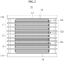
- FIG. 2 is a cross-sectional view illustrating an HT-PEMFC stack according to an example embodiment.
- an HT-PEMFC stack 20 may include end plate 110, middle end plate 111, a first cell assembly 12c, a second cell assembly 12d, a third cell assembly 12e, a plurality of cooling plates, a current collector 14, and a coolant inlet 18.
- the plurality of cooling plates may include a plurality of first cooling plates provided on top surfaces or bottom surfaces of the first cell assemblies 12c, respectively, a plurality of second cooling plate provided on top surfaces or bottom surfaces of the second cell assemblies 12d, respectively, a plurality of third cooling plates provided on top surfaces or bottom surfaces of the third cell assemblies 12e, respectively.
- the first cooling plate, the second cooling plate, and the third cooling plate may not be different components and may be determined based on a cell assembly on which a corresponding cooling plate is provided among the first cell assembly 12c, the second cell assembly 12d, and the third cell assembly 12e.
- the end plate 110 and middle end plate 111 may include a top end plate including the coolant inlet 18, and a bottom end plate provided to face the top end plate.
- the end plate 110 may also be referred to as the top end plate
- the middle end plate 111 may also be referred to as the bottom end plate.
- a coolant may flow in the top end plate 110 through the coolant inlet 18 and be injected into the plurality of cooling plates.
- the first cell assembly 12c may be provided closer to the top end plate 110 than the second cell assembly 12d.
- the third cell assembly 12e may be provided closer to the middle end plate 111 than the second cell assembly 12d.
- the first cell assembly 12c and the third cell assembly 12e are provided closer to the end plate 110 and middle end plate 111, respectively, and thus the end plate 110 and middle end plate 111 may absorb heat. Therefore, an appropriate temperature may be maintained.
- the second cell assembly 12d is provided relatively distant from the end plate 110 and middle end plate 111 compared to the first cell assembly 12c and the third cell assembly 12e. Thus, it is relatively difficult to maintain an appropriate temperature.
- the second cell assembly 12d may include a number of cell units less than a number of cell units included in each of the first cell assembly 12c and the third cell assembly 12e.
- the first cell assembly 12c may include five cell units
- the second cell assembly 12d may include four cell units
- the third cell assembly 12e may include five cell units.
- FIG. 3 is a cross-sectional view illustrating a portion of an HT-PEMFC stack according to an example embodiment.
- the HT-PEMFC stack 20 may include the end plate 110, a first cell assembly 12f, a second cell assembly 12g, a third cell assembly 12h, a fourth cell assembly 12i, a fifth cell assembly 12j, the current collector 14, a plurality of cooling plates, and the coolant inlet 18.
- the first cell assembly 12f, the second cell assembly 12g, the third cell assembly 12h, the fourth cell assembly 12i, and the fifth cell assembly 12j may be arranged to be distant from the coolant inlet 18.
- the first cell assembly 12f may be provided closest to the coolant inlet 18, and the fifth cell assembly 12j may be provided most distant from the coolant inlet 18.
- a number of cell units included in at least a portion of a plurality of cell assemblies may gradually decrease according to an increase in a distance between a corresponding cell assembly and the coolant inlet 18.
- the first cell assembly 12f may include nine cell units and a single dummy cell
- the second cell assembly 12g may include eight cell units and a single dummy cell
- the third cell assembly 12h may include seven cell units and a single dummy cell
- the fourth cell assembly 12i may include six cell units and a single dummy cell
- the fifth cell assembly 12j may include five cell units and a single dummy cell.
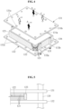
- FIG. 4 is an exploded perspective view illustrating a portion of an HT-PEMFC stack according to an example embodiment
- FIG. 5 is a cross-sectional view illustrating a portion of an HT-PEMFC stack according to an example embodiment.
- the cell assembly is provided between two cooling plates 131 and 132.
- the cell assembly may include a plurality of cell units 121, a dummy cell 122, and an insulating member 123.
- the cooling plate 131 attached on a top surface of the cell assembly may include an inlet hole and an outlet hole for hydrogen and oxygen, a plurality of holes 131c through which the plurality of clamping bars 112 of FIG. 1 passes, respectively, and holes 131a and 131b through which coolant hoses 135 and 136 pass, respectively.
- the cooling plate 132 attached on a bottom surface of the cell assembly may include an inlet hole and an outlet hole for hydrogen and oxygen, a plurality of holes 132c through which the plurality of clamping bars 112 of FIG. 1 passes, respectively, and holes 132a and 132b through which the coolant hoses 135 and 136 pass, respectively.
- FIG. 6 is a graph showing an enhancement in a temperature deviation by an HT-PEMFC according to an example embodiment.
- a point in time at which a time is 0 indicates a point in time at which a heat-up ends in the HT-PEMFC stack and a reaction starts in an MEA.
- a temperature difference between a top end plate and a bottom end plate is about 20°C at the point in time at which the time is 0.
- the bottom end plate is in direct contact with an external device and thus may have a temperature less than that of the top end plate due to a heat conduction. While the reaction continues in the MEA, a plurality of cooling plates may cool the MEA.
- an interval between the plurality of cooling plates may decrease according to an increase in a distance between a corresponding cooling plate and a coolant inlet or may decrease according to an increase in a distance between a corresponding cooling plate and each end plate.
- each of the cooling plates may allow a temperature of the HT-PEMFC stack to be uniform through the above structure. Accordingly, referring to the graph, it can be verified that the temperature difference between the top end plate and the bottom end plate approaches about 0°C when 120 minutes elapses.
- FIG. 7 is a top view illustrating a dummy cell according to an example embodiment
- FIG. 8 is a side view illustrating a dummy cell according to an example embodiment.
- a dummy cell 122 may include a dummy cell body 1221, a plurality of dummy cell holes 1222, and a plurality of thermocouples, for example, a first thermocouple TC1, a second thermocouple TC2, and a third thermocouple TC3.
- the dummy cell body 1221 may have a shape corresponding to the cell unit 121a of FIG.1 .
- the dummy cell body 1221 may overlap the cell unit 121 in a stacking direction of a stack.
- the dummy cell body 1221 may also have a bottom surface in a rectangular shape identical thereto.
- the plurality of dummy cell holes 1222 may communicate with a hydrogen inlet hole and outlet hole and an oxygen inlet hole and outlet hole included in the cell unit 121 of FIG. 4 , respectively.
- the plurality of thermocouples may be inserted in the dummy cell body 1221 in a direction vertical to the stacking direction. Only one of the plurality of thermocouples, for example, the first thermocouple TC1, the second thermocouple TC2, and the thermocouple TC3, may be provided. Each of the plurality of thermocouples, for example, the first thermocouple TC1, the second thermocouple TC2, and the thermocouple TC3, may be inserted at a different depth, and may measure a temperature at a different location.
- thermocouple TC1 may measure a temperature of a portion that is a relatively edge
- the third thermocouple TC3 may measure a temperature of a center portion
- the second thermocouple TC2 may measure a temperature between the first thermocouple TC1 and the third thermocouple TC3.
- the third thermocouple TC3 may measure a temperature of a center portion of a unit in which a reaction of the MEA most actively occurs.
- FIG. 9 is a top view illustrating an end plate according to an example embodiment.
- a plurality of relief springs 113 may be provided along an edge of the end plate 110.
- ten relief springs may be provided along an edge of the end plate 110.
- four relief springs 113 may be provided along each long side of the end plate 110, and three relief springs 113 may be provided along each short side of the end plate 110. That is, the ten relief springs 113 may be provided.
- the plurality of surface pressure measuring devices 119 may be provided below the relief springs 113, respectively.
- the plurality of surface pressure measuring devices 119 may uniformly measure a pressure applied to the end plate 110.
- ten surface pressure measuring devices 119 may also be provided.
- a pressure of a top left side is measured to be relatively low compared to a pressure applied to other portions of the end plate 110, a user may further rigidly fasten the relief spring 113 of the top left side to implement a normal coupling.
- MEA membrane electrode assembly
Landscapes
- Life Sciences & Earth Sciences (AREA)
- Engineering & Computer Science (AREA)
- Manufacturing & Machinery (AREA)
- Sustainable Development (AREA)
- Sustainable Energy (AREA)
- Chemical & Material Sciences (AREA)
- Chemical Kinetics & Catalysis (AREA)
- Electrochemistry (AREA)
- General Chemical & Material Sciences (AREA)
- Fuel Cell (AREA)
Claims (12)
- Hochtemperatur-Polymerelektrolytmembran-Brennstoffzellen- (High-Temperature Polymer Electrolyte Membrane Fuel Cell, HT-PEMFC) Stapel zur Optimierung eines Stapelbetriebs, wobei der HT-PEMFC-Stapel umfasst:einen Kühlmitteleinlass (18), der dafür konfiguriert ist, ein Kühlmittel einströmen zu lassen;eine Vielzahl von Kühlplatten (13, 131, 132), die dafür konfiguriert ist, das Kühlmittel, das durch den Kühlmitteleinlass (18) einströmt, zu bewegen; undeine Vielzahl von Zellanordnungen (12a, 12b, 12c, 12d, 12e, 12f, 12g, 12h), die jeweils zwischen zwei benachbarten Kühlplatten unter der Vielzahl von Kühlplatten (13, 131, 132) vorgesehen sind, wobei jede Zellanordnung eine Vielzahl von Zelleinheiten umfasst,dadurch gekennzeichnet, dassin mindestens einem Teil der Vielzahl von Zellanordnungen (12a, 12b, 12c, 12d, 12e, 12f, 12g, 12h), der dem Kühlmitteleinlass (18) am nächsten ist, eine Anzahl von Zelleinheiten, die in den Zellanordnungen des Teils der Vielzahl von Zellanordnungen (12a, 12b, 12c, 12d, 12e, 12f, 12g, 12h) enthalten sind, abnimmt entsprechend einer Zunahme des Abstands zwischen einer entsprechenden Zellanordnung und dem Kühlmitteleinlass (18).
- HT-PEMFC-Stapel nach einem der vorhergehenden Ansprüche, wobei die Vielzahl der Kühlplatten (13, 131, 132) umfasst:eine Vielzahl von ersten Kühlplatten; undeine Vielzahl von zweiten Kühlplatten, die im Vergleich zu der Vielzahl von ersten Kühlplatten relativ weit vom Kühlmitteleinlass entfernt sind, undwobei der Teil der Vielzahl von Zellanordnungen (12a, 12b, 12c, 12d, 12e, 12f, 12g, 12h) umfasst:eine oder mehrere erste Zellanordnungen, die zwischen zwei ersten Kühlplatten nebeneinander angeordnet sind und eine erste Anzahl von ersten Zelleneinheiten umfassen; undeine oder mehrere zweite Zellanordnungen, die zwischen zwei aneinander angrenzenden zweiten Kühlplatten vorgesehen sind und eine zweite Anzahl von zweiten Zelleneinheiten umfassen, wobei die zweite Anzahl geringer ist als die erste Anzahl.
- HT-PEMFC-Stapel nach Anspruch 2, der ferner umfasst:eine Endplatte (110), die dafür konfiguriert ist, die Vielzahl der ersten Kühlplatten, die Vielzahl der zweiten Kühlplatten, die erste Zelleneinheit und die zweite Zelleneinheit zu pressen,wobei die Vielzahl von Kühlplatten (13, 131, 132) ferner eine Vielzahl von dritten Kühlplatten umfasst, die näher an der Endplatte vorgesehen sind als die Vielzahl von zweiten Kühlplatten, unddie Vielzahl von Zellanordnungen (12a, 12b, 12c, 12d, 12e, 12f, 12g, 12h) ferner eine dritte Zellanordnung umfasst, die zwischen zwei dritten Kühlplatten benachbart zueinander vorgesehen ist und eine dritte Anzahl von dritten Zelleinheiten umfasst, wobei die dritte Anzahl größer als die zweite Anzahl ist.
- HT-PEMFC-Stapel nach Anspruch 3, wobei die Endplatte (110, 111) umfasst:eine obere Endplatte (110), die den Kühlmitteleinlass (18) umfasst; undeine untere Endplatte (110, 111), die so vorgesehen ist, dass sie der oberen Endplatte gegenüberliegt,wobei die erste Zellanordnung näher an der oberen Endplatte (110) angeordnet ist als die zweite Zellanordnung, unddie dritte Zellanordnung näher an der unteren Endplatte (110, 111) angeordnet ist als die zweite Zellanordnung.
- HT-PEMFC-Stapel nach einem der Ansprüche 2 bis 4, wobei die erste Zellanordnung umfasst:eine Vielzahl von ersten Zelleinheiten, die jeweils eine Membran-Elektroden-Verbindungsanordnung (MEA) umfassen; undeine erste Dummy-Zelle (122a), die ein Thermoelement umfasst und so konfiguriert ist, dass sie parallel zu der Vielzahl der ersten Zelleinheiten gestapelt werden kann.
- HT-PEMFC-Stapel nach Anspruch 5, wobei die erste Dummy-Zelle (122a) zwischen zwei ersten Zelleinheiten vorgesehen ist, die in der Mitte der Vielzahl der ersten Zelleinheiten vorgesehen sind.
- HT-PEMFC-Stapel nach Anspruch 5 oder 6, wobei die zweite Zellanordnung umfasst:eine Vielzahl von zweiten Zelleinheiten, die jeweils eine MEA umfassen; undeine zweite Dummy-Zelle (122b), die ein Thermoelement umfasst und dafür konfiguriert ist, parallel zu der Vielzahl der zweiten Zelleinheiten gestapelt zu werden.
- HT-PEMFC-Stapel nach einem der Ansprüche 2 bis 7, wobei die erste Zellanordnung umfasst:eine Vielzahl von ersten Zelleinheiten, die jeweils eine MEA umfassen; undein isolierendes Element, das so konfiguriert ist, dass es die Vielzahl der ersten Zelleinheiten umgibt.
- HT-PEMFC-Stapel nach Anspruch 8, der ferner umfasst:einen Kühlmittelschlauch (135), der so konfiguriert ist, dass das Kühlmittel in jede der Vielzahl von ersten Kühlplatten und der Vielzahl von zweiten Kühlplatten fließen kann,wobei mindestens ein Teil des Isolierelements zwischen der Vielzahl der ersten Zelleneinheiten und dem Kühlmittelschlauch vorgesehen ist.
- HT-PEMFC-Stapel nach einem der vorhergehenden Ansprüche, der ferner umfasst:eine Endplatte (110), die dafür konfiguriert ist, die Vielzahl von Kühlplatten (13, 131, 132) und die Vielzahl von Zellanordnungen (12a, 12b, 12c, 12d, 12e, 12f, 12g, 12h) zu pressen; undeine Oberflächendruckmessvorrichtung, die an der Endplatte (110) vorgesehen und dafür konfiguriert ist, einen Druck zu messen, der auf die Vielzahl von Kühlplatten (13, 131, 132) und die Vielzahl von Zellanordnungen (12a, 12b, 12c, 12d, 12e, 12f, 12g, 12h) durch die Endplatte (110) ausgeübt wird.
- HT-PEMFC-Stapel nach Anspruch 10, der ferner umfasst:eine Klemmstange (112), die zum Koppeln mit der Endplatte (110) konfiguriert ist; undeine Entlastungsfeder (113), die an einem Ende der Klemmstange vorgesehen und dafür konfiguriert ist, die Endplatte (110) zu drücken,wobei die Oberflächendruckmessvorrichtung zwischen der Entlastungsfeder und der Endplatte angeordnet ist.
- HT-PEMFC-Stapel nach Anspruch 11, wobei eine Vielzahl von Entlastungsfedern (113) entlang einer Kante der Endplatte (110) vorgesehen ist, und
die Oberflächendruckmessvorrichtung unterhalb jeder der Vielzahl von Entlastungsfedern (113) angeordnet ist.
Applications Claiming Priority (1)
| Application Number | Priority Date | Filing Date | Title |
|---|---|---|---|
| KR1020180048538A KR20190124498A (ko) | 2018-04-26 | 2018-04-26 | 스택 운전 최적화를 위한 고온 고분자전해질막 연료전지 스택 |
Publications (2)
| Publication Number | Publication Date |
|---|---|
| EP3561933A1 EP3561933A1 (de) | 2019-10-30 |
| EP3561933B1 true EP3561933B1 (de) | 2024-08-28 |
Family
ID=63762408
Family Applications (1)
| Application Number | Title | Priority Date | Filing Date |
|---|---|---|---|
| EP18198690.2A Active EP3561933B1 (de) | 2018-04-26 | 2018-10-04 | Hochtemperaturpolymerelektrolytmembranbrennstoffzellenstapel zur optimierung des stapelbetriebs |
Country Status (4)
| Country | Link |
|---|---|
| EP (1) | EP3561933B1 (de) |
| KR (1) | KR20190124498A (de) |
| CN (1) | CN110416574A (de) |
| DK (1) | DK3561933T3 (de) |
Families Citing this family (3)
| Publication number | Priority date | Publication date | Assignee | Title |
|---|---|---|---|---|
| KR102900657B1 (ko) | 2020-07-31 | 2025-12-15 | 주식회사 엘지에너지솔루션 | 필름형 압력 센서를 포함하는 전지 셀 지그 및 이를 이용한 전지 셀의 스웰링 측정 방법 |
| JP2024512795A (ja) * | 2021-04-02 | 2024-03-19 | アドベント テクノロジーズ エルエルシー | 燃料電池電力システム |
| CN118712409B (zh) * | 2024-05-27 | 2025-09-05 | 广州汽车集团股份有限公司 | 一种燃料电池冷却结构及燃料电池、汽车 |
Citations (1)
| Publication number | Priority date | Publication date | Assignee | Title |
|---|---|---|---|---|
| EP2413422A1 (de) * | 2010-07-30 | 2012-02-01 | Samsung Electronics Co., Ltd. | Stapel mit gleichmäßiger Temperaturverteilung und Betriebsverfahren dafür |
Family Cites Families (7)
| Publication number | Priority date | Publication date | Assignee | Title |
|---|---|---|---|---|
| JPH05242903A (ja) * | 1992-02-27 | 1993-09-21 | Toshiba Corp | 燃料電池積層体 |
| KR100495736B1 (ko) * | 2001-04-03 | 2005-06-16 | 마쯔시다덴기산교 가부시키가이샤 | 고분자 전해질형 연료전지 및 그 운전방법 |
| CN101138120B (zh) * | 2005-03-11 | 2010-12-01 | Bdfip控股有限公司 | 燃料电池堆和关闭燃料电池堆的方法 |
| KR20100114686A (ko) * | 2009-04-16 | 2010-10-26 | 삼성전자주식회사 | 복수 개의 발전 모듈들을 갖는 연료 전지 스택 및 연료 전지 시스템 |
| KR101102177B1 (ko) * | 2009-08-13 | 2012-01-02 | 두산중공업 주식회사 | 연료전지의 면압제어장치 |
| KR101283022B1 (ko) * | 2011-06-10 | 2013-07-08 | 현대자동차주식회사 | 내부온도 측정이 가능한 연료전지의 스택 |
| KR101768128B1 (ko) * | 2016-02-16 | 2017-08-16 | 한국에너지기술연구원 | 독립형 냉각판을 구비하는 고온 고분자 전해질 막 연료 전지 스택 및 그 제조 방법 |
-
2018
- 2018-04-26 KR KR1020180048538A patent/KR20190124498A/ko not_active Ceased
- 2018-10-04 DK DK18198690.2T patent/DK3561933T3/da active
- 2018-10-04 EP EP18198690.2A patent/EP3561933B1/de active Active
- 2018-10-24 CN CN201811245214.XA patent/CN110416574A/zh active Pending
Patent Citations (1)
| Publication number | Priority date | Publication date | Assignee | Title |
|---|---|---|---|---|
| EP2413422A1 (de) * | 2010-07-30 | 2012-02-01 | Samsung Electronics Co., Ltd. | Stapel mit gleichmäßiger Temperaturverteilung und Betriebsverfahren dafür |
Also Published As
| Publication number | Publication date |
|---|---|
| DK3561933T3 (da) | 2024-09-23 |
| EP3561933A1 (de) | 2019-10-30 |
| KR20190124498A (ko) | 2019-11-05 |
| CN110416574A (zh) | 2019-11-05 |
Similar Documents
| Publication | Publication Date | Title |
|---|---|---|
| US10270116B2 (en) | High-temperature polymer electrolyte membrane fuel cell stack having independent cooling plate and method of producing the same | |
| JP4948823B2 (ja) | 燃料電池スタック | |
| US20070207372A1 (en) | Fuel cell | |
| JPH08180883A (ja) | 固体高分子電解質型燃料電池 | |
| US7419739B2 (en) | Flexible bipolar plate | |
| US8927170B2 (en) | Flow field plate for reduced pressure drop in coolant | |
| JP2019121530A (ja) | 発電セル | |
| EP3561933B1 (de) | Hochtemperaturpolymerelektrolytmembranbrennstoffzellenstapel zur optimierung des stapelbetriebs | |
| US10644329B2 (en) | Fuel cell stack having a displacement absorbing member disposed in a cooling fluid channel | |
| KR101261948B1 (ko) | 연료전지 스택 | |
| KR102666114B1 (ko) | 분리판 및 이를 포함하는 연료전지 스택 | |
| US12027730B2 (en) | Fuel cell stack | |
| KR101759652B1 (ko) | 고분자 전해질형 연료전지, 연료전지 스택 및 엔드 플레이트 | |
| CN105378998B (zh) | 变形吸收构件和燃料电池 | |
| US12603303B2 (en) | Fuel cell stack | |
| US11552311B2 (en) | Fuel cell | |
| KR102329252B1 (ko) | 스택 운전 최적화를 위한 고온 고분자전해질막 연료전지 스택 | |
| JP5398338B2 (ja) | 燃料電池スタック | |
| JP5443254B2 (ja) | 燃料電池 | |
| KR101979837B1 (ko) | 연료 전지용 독립형 냉각판 및 이를 포함하는 연료 전지 | |
| US10297842B2 (en) | Fuel cell stack | |
| JP2015191841A (ja) | 燃料電池スタック | |
| US20250385277A1 (en) | Separator for fuel cell | |
| KR102952875B1 (ko) | 연료 전지 | |
| US12068510B2 (en) | Fuel cell stack |
Legal Events
| Date | Code | Title | Description |
|---|---|---|---|
| PUAI | Public reference made under article 153(3) epc to a published international application that has entered the european phase |
Free format text: ORIGINAL CODE: 0009012 |
|
| STAA | Information on the status of an ep patent application or granted ep patent |
Free format text: STATUS: REQUEST FOR EXAMINATION WAS MADE |
|
| 17P | Request for examination filed |
Effective date: 20181004 |
|
| AK | Designated contracting states |
Kind code of ref document: A1 Designated state(s): AL AT BE BG CH CY CZ DE DK EE ES FI FR GB GR HR HU IE IS IT LI LT LU LV MC MK MT NL NO PL PT RO RS SE SI SK SM TR |
|
| AX | Request for extension of the european patent |
Extension state: BA ME |
|
| STAA | Information on the status of an ep patent application or granted ep patent |
Free format text: STATUS: EXAMINATION IS IN PROGRESS |
|
| 17Q | First examination report despatched |
Effective date: 20191111 |
|
| GRAP | Despatch of communication of intention to grant a patent |
Free format text: ORIGINAL CODE: EPIDOSNIGR1 |
|
| STAA | Information on the status of an ep patent application or granted ep patent |
Free format text: STATUS: GRANT OF PATENT IS INTENDED |
|
| RIC1 | Information provided on ipc code assigned before grant |
Ipc: H01M 8/00 20160101ALN20240523BHEP Ipc: H01M 8/1018 20160101ALN20240523BHEP Ipc: H01M 8/10 20160101ALN20240523BHEP Ipc: H01M 8/1004 20160101ALN20240523BHEP Ipc: H01M 8/242 20160101ALI20240523BHEP Ipc: H01M 8/2432 20160101ALI20240523BHEP Ipc: H01M 8/0432 20160101ALI20240523BHEP Ipc: H01M 8/04007 20160101ALI20240523BHEP Ipc: H01M 8/0297 20160101ALI20240523BHEP Ipc: H01M 8/0271 20160101ALI20240523BHEP Ipc: H01M 8/249 20160101ALI20240523BHEP Ipc: H01M 8/241 20160101AFI20240523BHEP |
|
| INTG | Intention to grant announced |
Effective date: 20240613 |
|
| GRAS | Grant fee paid |
Free format text: ORIGINAL CODE: EPIDOSNIGR3 |
|
| GRAA | (expected) grant |
Free format text: ORIGINAL CODE: 0009210 |
|
| STAA | Information on the status of an ep patent application or granted ep patent |
Free format text: STATUS: THE PATENT HAS BEEN GRANTED |
|
| AK | Designated contracting states |
Kind code of ref document: B1 Designated state(s): AL AT BE BG CH CY CZ DE DK EE ES FI FR GB GR HR HU IE IS IT LI LT LU LV MC MK MT NL NO PL PT RO RS SE SI SK SM TR |
|
| REG | Reference to a national code |
Ref country code: GB Ref legal event code: FG4D |
|
| REG | Reference to a national code |
Ref country code: CH Ref legal event code: EP |
|
| REG | Reference to a national code |
Ref country code: DE Ref legal event code: R096 Ref document number: 602018073566 Country of ref document: DE |
|
| REG | Reference to a national code |
Ref country code: DK Ref legal event code: T3 Effective date: 20240919 |
|
| REG | Reference to a national code |
Ref country code: IE Ref legal event code: FG4D |
|
| REG | Reference to a national code |
Ref country code: LT Ref legal event code: MG9D |
|
| PG25 | Lapsed in a contracting state [announced via postgrant information from national office to epo] |
Ref country code: NO Free format text: LAPSE BECAUSE OF FAILURE TO SUBMIT A TRANSLATION OF THE DESCRIPTION OR TO PAY THE FEE WITHIN THE PRESCRIBED TIME-LIMIT Effective date: 20241128 |
|
| REG | Reference to a national code |
Ref country code: AT Ref legal event code: MK05 Ref document number: 1718989 Country of ref document: AT Kind code of ref document: T Effective date: 20240828 |
|
| PG25 | Lapsed in a contracting state [announced via postgrant information from national office to epo] |
Ref country code: PL Free format text: LAPSE BECAUSE OF FAILURE TO SUBMIT A TRANSLATION OF THE DESCRIPTION OR TO PAY THE FEE WITHIN THE PRESCRIBED TIME-LIMIT Effective date: 20240828 Ref country code: PT Free format text: LAPSE BECAUSE OF FAILURE TO SUBMIT A TRANSLATION OF THE DESCRIPTION OR TO PAY THE FEE WITHIN THE PRESCRIBED TIME-LIMIT Effective date: 20241230 Ref country code: NL Free format text: LAPSE BECAUSE OF FAILURE TO SUBMIT A TRANSLATION OF THE DESCRIPTION OR TO PAY THE FEE WITHIN THE PRESCRIBED TIME-LIMIT Effective date: 20240828 Ref country code: GR Free format text: LAPSE BECAUSE OF FAILURE TO SUBMIT A TRANSLATION OF THE DESCRIPTION OR TO PAY THE FEE WITHIN THE PRESCRIBED TIME-LIMIT Effective date: 20241129 Ref country code: FI Free format text: LAPSE BECAUSE OF FAILURE TO SUBMIT A TRANSLATION OF THE DESCRIPTION OR TO PAY THE FEE WITHIN THE PRESCRIBED TIME-LIMIT Effective date: 20240828 |
|
| PG25 | Lapsed in a contracting state [announced via postgrant information from national office to epo] |
Ref country code: BG Free format text: LAPSE BECAUSE OF FAILURE TO SUBMIT A TRANSLATION OF THE DESCRIPTION OR TO PAY THE FEE WITHIN THE PRESCRIBED TIME-LIMIT Effective date: 20240828 |
|
| PG25 | Lapsed in a contracting state [announced via postgrant information from national office to epo] |
Ref country code: LV Free format text: LAPSE BECAUSE OF FAILURE TO SUBMIT A TRANSLATION OF THE DESCRIPTION OR TO PAY THE FEE WITHIN THE PRESCRIBED TIME-LIMIT Effective date: 20240828 |
|
| REG | Reference to a national code |
Ref country code: NL Ref legal event code: MP Effective date: 20240828 |
|
| PG25 | Lapsed in a contracting state [announced via postgrant information from national office to epo] |
Ref country code: AT Free format text: LAPSE BECAUSE OF FAILURE TO SUBMIT A TRANSLATION OF THE DESCRIPTION OR TO PAY THE FEE WITHIN THE PRESCRIBED TIME-LIMIT Effective date: 20240828 Ref country code: IS Free format text: LAPSE BECAUSE OF FAILURE TO SUBMIT A TRANSLATION OF THE DESCRIPTION OR TO PAY THE FEE WITHIN THE PRESCRIBED TIME-LIMIT Effective date: 20241228 |
|
| PG25 | Lapsed in a contracting state [announced via postgrant information from national office to epo] |
Ref country code: HR Free format text: LAPSE BECAUSE OF FAILURE TO SUBMIT A TRANSLATION OF THE DESCRIPTION OR TO PAY THE FEE WITHIN THE PRESCRIBED TIME-LIMIT Effective date: 20240828 |
|
| PG25 | Lapsed in a contracting state [announced via postgrant information from national office to epo] |
Ref country code: RS Free format text: LAPSE BECAUSE OF FAILURE TO SUBMIT A TRANSLATION OF THE DESCRIPTION OR TO PAY THE FEE WITHIN THE PRESCRIBED TIME-LIMIT Effective date: 20241128 Ref country code: ES Free format text: LAPSE BECAUSE OF FAILURE TO SUBMIT A TRANSLATION OF THE DESCRIPTION OR TO PAY THE FEE WITHIN THE PRESCRIBED TIME-LIMIT Effective date: 20240828 |
|
| PG25 | Lapsed in a contracting state [announced via postgrant information from national office to epo] |
Ref country code: PT Free format text: LAPSE BECAUSE OF FAILURE TO SUBMIT A TRANSLATION OF THE DESCRIPTION OR TO PAY THE FEE WITHIN THE PRESCRIBED TIME-LIMIT Effective date: 20241230 Ref country code: PL Free format text: LAPSE BECAUSE OF FAILURE TO SUBMIT A TRANSLATION OF THE DESCRIPTION OR TO PAY THE FEE WITHIN THE PRESCRIBED TIME-LIMIT Effective date: 20240828 Ref country code: NO Free format text: LAPSE BECAUSE OF FAILURE TO SUBMIT A TRANSLATION OF THE DESCRIPTION OR TO PAY THE FEE WITHIN THE PRESCRIBED TIME-LIMIT Effective date: 20241128 Ref country code: NL Free format text: LAPSE BECAUSE OF FAILURE TO SUBMIT A TRANSLATION OF THE DESCRIPTION OR TO PAY THE FEE WITHIN THE PRESCRIBED TIME-LIMIT Effective date: 20240828 Ref country code: LV Free format text: LAPSE BECAUSE OF FAILURE TO SUBMIT A TRANSLATION OF THE DESCRIPTION OR TO PAY THE FEE WITHIN THE PRESCRIBED TIME-LIMIT Effective date: 20240828 Ref country code: IS Free format text: LAPSE BECAUSE OF FAILURE TO SUBMIT A TRANSLATION OF THE DESCRIPTION OR TO PAY THE FEE WITHIN THE PRESCRIBED TIME-LIMIT Effective date: 20241228 Ref country code: HR Free format text: LAPSE BECAUSE OF FAILURE TO SUBMIT A TRANSLATION OF THE DESCRIPTION OR TO PAY THE FEE WITHIN THE PRESCRIBED TIME-LIMIT Effective date: 20240828 Ref country code: GR Free format text: LAPSE BECAUSE OF FAILURE TO SUBMIT A TRANSLATION OF THE DESCRIPTION OR TO PAY THE FEE WITHIN THE PRESCRIBED TIME-LIMIT Effective date: 20241129 Ref country code: FI Free format text: LAPSE BECAUSE OF FAILURE TO SUBMIT A TRANSLATION OF THE DESCRIPTION OR TO PAY THE FEE WITHIN THE PRESCRIBED TIME-LIMIT Effective date: 20240828 Ref country code: ES Free format text: LAPSE BECAUSE OF FAILURE TO SUBMIT A TRANSLATION OF THE DESCRIPTION OR TO PAY THE FEE WITHIN THE PRESCRIBED TIME-LIMIT Effective date: 20240828 Ref country code: BG Free format text: LAPSE BECAUSE OF FAILURE TO SUBMIT A TRANSLATION OF THE DESCRIPTION OR TO PAY THE FEE WITHIN THE PRESCRIBED TIME-LIMIT Effective date: 20240828 Ref country code: AT Free format text: LAPSE BECAUSE OF FAILURE TO SUBMIT A TRANSLATION OF THE DESCRIPTION OR TO PAY THE FEE WITHIN THE PRESCRIBED TIME-LIMIT Effective date: 20240828 Ref country code: RS Free format text: LAPSE BECAUSE OF FAILURE TO SUBMIT A TRANSLATION OF THE DESCRIPTION OR TO PAY THE FEE WITHIN THE PRESCRIBED TIME-LIMIT Effective date: 20241128 |
|
| PG25 | Lapsed in a contracting state [announced via postgrant information from national office to epo] |
Ref country code: RO Free format text: LAPSE BECAUSE OF FAILURE TO SUBMIT A TRANSLATION OF THE DESCRIPTION OR TO PAY THE FEE WITHIN THE PRESCRIBED TIME-LIMIT Effective date: 20240828 Ref country code: SM Free format text: LAPSE BECAUSE OF FAILURE TO SUBMIT A TRANSLATION OF THE DESCRIPTION OR TO PAY THE FEE WITHIN THE PRESCRIBED TIME-LIMIT Effective date: 20240828 |
|
| PG25 | Lapsed in a contracting state [announced via postgrant information from national office to epo] |
Ref country code: EE Free format text: LAPSE BECAUSE OF FAILURE TO SUBMIT A TRANSLATION OF THE DESCRIPTION OR TO PAY THE FEE WITHIN THE PRESCRIBED TIME-LIMIT Effective date: 20240828 |
|
| PG25 | Lapsed in a contracting state [announced via postgrant information from national office to epo] |
Ref country code: CZ Free format text: LAPSE BECAUSE OF FAILURE TO SUBMIT A TRANSLATION OF THE DESCRIPTION OR TO PAY THE FEE WITHIN THE PRESCRIBED TIME-LIMIT Effective date: 20240828 |
|
| PG25 | Lapsed in a contracting state [announced via postgrant information from national office to epo] |
Ref country code: IT Free format text: LAPSE BECAUSE OF FAILURE TO SUBMIT A TRANSLATION OF THE DESCRIPTION OR TO PAY THE FEE WITHIN THE PRESCRIBED TIME-LIMIT Effective date: 20240828 Ref country code: SK Free format text: LAPSE BECAUSE OF FAILURE TO SUBMIT A TRANSLATION OF THE DESCRIPTION OR TO PAY THE FEE WITHIN THE PRESCRIBED TIME-LIMIT Effective date: 20240828 |
|
| REG | Reference to a national code |
Ref country code: CH Ref legal event code: PL Ref country code: DE Ref legal event code: R097 Ref document number: 602018073566 Country of ref document: DE |
|
| PLBE | No opposition filed within time limit |
Free format text: ORIGINAL CODE: 0009261 |
|
| STAA | Information on the status of an ep patent application or granted ep patent |
Free format text: STATUS: NO OPPOSITION FILED WITHIN TIME LIMIT |
|
| PG25 | Lapsed in a contracting state [announced via postgrant information from national office to epo] |
Ref country code: MC Free format text: LAPSE BECAUSE OF FAILURE TO SUBMIT A TRANSLATION OF THE DESCRIPTION OR TO PAY THE FEE WITHIN THE PRESCRIBED TIME-LIMIT Effective date: 20240828 |
|
| PG25 | Lapsed in a contracting state [announced via postgrant information from national office to epo] |
Ref country code: BE Free format text: LAPSE BECAUSE OF NON-PAYMENT OF DUE FEES Effective date: 20241031 Ref country code: LU Free format text: LAPSE BECAUSE OF NON-PAYMENT OF DUE FEES Effective date: 20241004 |
|
| PG25 | Lapsed in a contracting state [announced via postgrant information from national office to epo] |
Ref country code: FR Free format text: LAPSE BECAUSE OF NON-PAYMENT OF DUE FEES Effective date: 20241028 |
|
| GBPC | Gb: european patent ceased through non-payment of renewal fee |
Effective date: 20241128 |
|
| PG25 | Lapsed in a contracting state [announced via postgrant information from national office to epo] |
Ref country code: CH Free format text: LAPSE BECAUSE OF NON-PAYMENT OF DUE FEES Effective date: 20241031 |
|
| 26N | No opposition filed |
Effective date: 20250530 |
|
| REG | Reference to a national code |
Ref country code: BE Ref legal event code: MM Effective date: 20241031 |
|
| PG25 | Lapsed in a contracting state [announced via postgrant information from national office to epo] |
Ref country code: SE Free format text: LAPSE BECAUSE OF FAILURE TO SUBMIT A TRANSLATION OF THE DESCRIPTION OR TO PAY THE FEE WITHIN THE PRESCRIBED TIME-LIMIT Effective date: 20240828 |
|
| PG25 | Lapsed in a contracting state [announced via postgrant information from national office to epo] |
Ref country code: GB Free format text: LAPSE BECAUSE OF NON-PAYMENT OF DUE FEES Effective date: 20241128 |
|
| PG25 | Lapsed in a contracting state [announced via postgrant information from national office to epo] |
Ref country code: IE Free format text: LAPSE BECAUSE OF NON-PAYMENT OF DUE FEES Effective date: 20241004 |
|
| PGFP | Annual fee paid to national office [announced via postgrant information from national office to epo] |
Ref country code: DE Payment date: 20250902 Year of fee payment: 8 |
|
| PGFP | Annual fee paid to national office [announced via postgrant information from national office to epo] |
Ref country code: DK Payment date: 20251014 Year of fee payment: 8 |
|
| PG25 | Lapsed in a contracting state [announced via postgrant information from national office to epo] |
Ref country code: CY Free format text: LAPSE BECAUSE OF FAILURE TO SUBMIT A TRANSLATION OF THE DESCRIPTION OR TO PAY THE FEE WITHIN THE PRESCRIBED TIME-LIMIT; INVALID AB INITIO Effective date: 20181004 |
|
| PG25 | Lapsed in a contracting state [announced via postgrant information from national office to epo] |
Ref country code: HU Free format text: LAPSE BECAUSE OF FAILURE TO SUBMIT A TRANSLATION OF THE DESCRIPTION OR TO PAY THE FEE WITHIN THE PRESCRIBED TIME-LIMIT; INVALID AB INITIO Effective date: 20181004 |