EP3561434A1 - Heat exchanger, method for manufacturing same, and refrigeration cycle device - Google Patents
Heat exchanger, method for manufacturing same, and refrigeration cycle device Download PDFInfo
- Publication number
- EP3561434A1 EP3561434A1 EP16924289.8A EP16924289A EP3561434A1 EP 3561434 A1 EP3561434 A1 EP 3561434A1 EP 16924289 A EP16924289 A EP 16924289A EP 3561434 A1 EP3561434 A1 EP 3561434A1
- Authority
- EP
- European Patent Office
- Prior art keywords
- heat exchanger
- flat tube
- fin
- bonding agent
- exchanger according
- Prior art date
- Legal status (The legal status is an assumption and is not a legal conclusion. Google has not performed a legal analysis and makes no representation as to the accuracy of the status listed.)
- Granted
Links
Images







Classifications
-
- F—MECHANICAL ENGINEERING; LIGHTING; HEATING; WEAPONS; BLASTING
- F28—HEAT EXCHANGE IN GENERAL
- F28D—HEAT-EXCHANGE APPARATUS, NOT PROVIDED FOR IN ANOTHER SUBCLASS, IN WHICH THE HEAT-EXCHANGE MEDIA DO NOT COME INTO DIRECT CONTACT
- F28D1/00—Heat-exchange apparatus having stationary conduit assemblies for one heat-exchange medium only, the media being in contact with different sides of the conduit wall, in which the other heat-exchange medium is a large body of fluid, e.g. domestic or motor car radiators
- F28D1/02—Heat-exchange apparatus having stationary conduit assemblies for one heat-exchange medium only, the media being in contact with different sides of the conduit wall, in which the other heat-exchange medium is a large body of fluid, e.g. domestic or motor car radiators with heat-exchange conduits immersed in the body of fluid
- F28D1/04—Heat-exchange apparatus having stationary conduit assemblies for one heat-exchange medium only, the media being in contact with different sides of the conduit wall, in which the other heat-exchange medium is a large body of fluid, e.g. domestic or motor car radiators with heat-exchange conduits immersed in the body of fluid with tubular conduits
- F28D1/053—Heat-exchange apparatus having stationary conduit assemblies for one heat-exchange medium only, the media being in contact with different sides of the conduit wall, in which the other heat-exchange medium is a large body of fluid, e.g. domestic or motor car radiators with heat-exchange conduits immersed in the body of fluid with tubular conduits the conduits being straight
- F28D1/0535—Heat-exchange apparatus having stationary conduit assemblies for one heat-exchange medium only, the media being in contact with different sides of the conduit wall, in which the other heat-exchange medium is a large body of fluid, e.g. domestic or motor car radiators with heat-exchange conduits immersed in the body of fluid with tubular conduits the conduits being straight the conduits having a non-circular cross-section
- F28D1/05366—Assemblies of conduits connected to common headers, e.g. core type radiators
-
- C—CHEMISTRY; METALLURGY
- C22—METALLURGY; FERROUS OR NON-FERROUS ALLOYS; TREATMENT OF ALLOYS OR NON-FERROUS METALS
- C22C—ALLOYS
- C22C21/00—Alloys based on aluminium
- C22C21/10—Alloys based on aluminium with zinc as the next major constituent
-
- C—CHEMISTRY; METALLURGY
- C09—DYES; PAINTS; POLISHES; NATURAL RESINS; ADHESIVES; COMPOSITIONS NOT OTHERWISE PROVIDED FOR; APPLICATIONS OF MATERIALS NOT OTHERWISE PROVIDED FOR
- C09J—ADHESIVES; NON-MECHANICAL ASPECTS OF ADHESIVE PROCESSES IN GENERAL; ADHESIVE PROCESSES NOT PROVIDED FOR ELSEWHERE; USE OF MATERIALS AS ADHESIVES
- C09J5/00—Adhesive processes in general; Adhesive processes not provided for elsewhere, e.g. relating to primers
- C09J5/02—Adhesive processes in general; Adhesive processes not provided for elsewhere, e.g. relating to primers involving pretreatment of the surfaces to be joined
-
- C—CHEMISTRY; METALLURGY
- C22—METALLURGY; FERROUS OR NON-FERROUS ALLOYS; TREATMENT OF ALLOYS OR NON-FERROUS METALS
- C22C—ALLOYS
- C22C21/00—Alloys based on aluminium
-
- F—MECHANICAL ENGINEERING; LIGHTING; HEATING; WEAPONS; BLASTING
- F28—HEAT EXCHANGE IN GENERAL
- F28F—DETAILS OF HEAT-EXCHANGE AND HEAT-TRANSFER APPARATUS, OF GENERAL APPLICATION
- F28F1/00—Tubular elements; Assemblies of tubular elements
- F28F1/02—Tubular elements of cross-section which is non-circular
- F28F1/022—Tubular elements of cross-section which is non-circular with multiple channels
-
- F—MECHANICAL ENGINEERING; LIGHTING; HEATING; WEAPONS; BLASTING
- F28—HEAT EXCHANGE IN GENERAL
- F28F—DETAILS OF HEAT-EXCHANGE AND HEAT-TRANSFER APPARATUS, OF GENERAL APPLICATION
- F28F1/00—Tubular elements; Assemblies of tubular elements
- F28F1/10—Tubular elements and assemblies thereof with means for increasing heat-transfer area, e.g. with fins, with projections, with recesses
- F28F1/12—Tubular elements and assemblies thereof with means for increasing heat-transfer area, e.g. with fins, with projections, with recesses the means being only outside the tubular element
- F28F1/126—Tubular elements and assemblies thereof with means for increasing heat-transfer area, e.g. with fins, with projections, with recesses the means being only outside the tubular element consisting of zig-zag shaped fins
-
- F—MECHANICAL ENGINEERING; LIGHTING; HEATING; WEAPONS; BLASTING
- F28—HEAT EXCHANGE IN GENERAL
- F28F—DETAILS OF HEAT-EXCHANGE AND HEAT-TRANSFER APPARATUS, OF GENERAL APPLICATION
- F28F13/00—Arrangements for modifying heat-transfer, e.g. increasing, decreasing
- F28F13/18—Arrangements for modifying heat-transfer, e.g. increasing, decreasing by applying coatings, e.g. radiation-absorbing, radiation-reflecting; by surface treatment, e.g. polishing
-
- F—MECHANICAL ENGINEERING; LIGHTING; HEATING; WEAPONS; BLASTING
- F28—HEAT EXCHANGE IN GENERAL
- F28F—DETAILS OF HEAT-EXCHANGE AND HEAT-TRANSFER APPARATUS, OF GENERAL APPLICATION
- F28F19/00—Preventing the formation of deposits or corrosion, e.g. by using filters or scrapers
- F28F19/02—Preventing the formation of deposits or corrosion, e.g. by using filters or scrapers by using coatings, e.g. vitreous or enamel coatings
-
- F—MECHANICAL ENGINEERING; LIGHTING; HEATING; WEAPONS; BLASTING
- F28—HEAT EXCHANGE IN GENERAL
- F28F—DETAILS OF HEAT-EXCHANGE AND HEAT-TRANSFER APPARATUS, OF GENERAL APPLICATION
- F28F19/00—Preventing the formation of deposits or corrosion, e.g. by using filters or scrapers
- F28F19/02—Preventing the formation of deposits or corrosion, e.g. by using filters or scrapers by using coatings, e.g. vitreous or enamel coatings
- F28F19/06—Preventing the formation of deposits or corrosion, e.g. by using filters or scrapers by using coatings, e.g. vitreous or enamel coatings of metal
-
- C—CHEMISTRY; METALLURGY
- C09—DYES; PAINTS; POLISHES; NATURAL RESINS; ADHESIVES; COMPOSITIONS NOT OTHERWISE PROVIDED FOR; APPLICATIONS OF MATERIALS NOT OTHERWISE PROVIDED FOR
- C09J—ADHESIVES; NON-MECHANICAL ASPECTS OF ADHESIVE PROCESSES IN GENERAL; ADHESIVE PROCESSES NOT PROVIDED FOR ELSEWHERE; USE OF MATERIALS AS ADHESIVES
- C09J2463/00—Presence of epoxy resin
-
- F—MECHANICAL ENGINEERING; LIGHTING; HEATING; WEAPONS; BLASTING
- F28—HEAT EXCHANGE IN GENERAL
- F28D—HEAT-EXCHANGE APPARATUS, NOT PROVIDED FOR IN ANOTHER SUBCLASS, IN WHICH THE HEAT-EXCHANGE MEDIA DO NOT COME INTO DIRECT CONTACT
- F28D21/00—Heat-exchange apparatus not covered by any of the groups F28D1/00 - F28D20/00
- F28D2021/0019—Other heat exchangers for particular applications; Heat exchange systems not otherwise provided for
- F28D2021/0068—Other heat exchangers for particular applications; Heat exchange systems not otherwise provided for for refrigerant cycles
- F28D2021/0071—Evaporators
-
- F—MECHANICAL ENGINEERING; LIGHTING; HEATING; WEAPONS; BLASTING
- F28—HEAT EXCHANGE IN GENERAL
- F28D—HEAT-EXCHANGE APPARATUS, NOT PROVIDED FOR IN ANOTHER SUBCLASS, IN WHICH THE HEAT-EXCHANGE MEDIA DO NOT COME INTO DIRECT CONTACT
- F28D21/00—Heat-exchange apparatus not covered by any of the groups F28D1/00 - F28D20/00
- F28D2021/0019—Other heat exchangers for particular applications; Heat exchange systems not otherwise provided for
- F28D2021/008—Other heat exchangers for particular applications; Heat exchange systems not otherwise provided for for vehicles
- F28D2021/0085—Evaporators
-
- F—MECHANICAL ENGINEERING; LIGHTING; HEATING; WEAPONS; BLASTING
- F28—HEAT EXCHANGE IN GENERAL
- F28F—DETAILS OF HEAT-EXCHANGE AND HEAT-TRANSFER APPARATUS, OF GENERAL APPLICATION
- F28F19/00—Preventing the formation of deposits or corrosion, e.g. by using filters or scrapers
- F28F19/02—Preventing the formation of deposits or corrosion, e.g. by using filters or scrapers by using coatings, e.g. vitreous or enamel coatings
- F28F19/04—Preventing the formation of deposits or corrosion, e.g. by using filters or scrapers by using coatings, e.g. vitreous or enamel coatings of rubber; of plastics material; of varnish
-
- F—MECHANICAL ENGINEERING; LIGHTING; HEATING; WEAPONS; BLASTING
- F28—HEAT EXCHANGE IN GENERAL
- F28F—DETAILS OF HEAT-EXCHANGE AND HEAT-TRANSFER APPARATUS, OF GENERAL APPLICATION
- F28F2245/00—Coatings; Surface treatments
- F28F2245/02—Coatings; Surface treatments hydrophilic
-
- F—MECHANICAL ENGINEERING; LIGHTING; HEATING; WEAPONS; BLASTING
- F28—HEAT EXCHANGE IN GENERAL
- F28F—DETAILS OF HEAT-EXCHANGE AND HEAT-TRANSFER APPARATUS, OF GENERAL APPLICATION
- F28F2275/00—Fastening; Joining
- F28F2275/02—Fastening; Joining by using bonding materials; by embedding elements in particular materials
Definitions
- the present invention relates to heat exchangers and methods of manufacturing thereof, and refrigeration cycle apparatuses, and more particularly to a heat exchanger having a fin bonded to a heat transfer tube, a method of manufacturing the heat exchanger, and a refrigeration cycle apparatus including such a heat exchanger.
- a heat exchanger having a combination of a flat tube and a corrugated fin is used.
- the flat tube is a form of heat transfer tube through which refrigerant flows, which has a flat cross-sectional shape so as to achieve efficient heat transfer.
- the corrugated fin is a fin formed by bending a plate-like fin into a bellows shape.
- a plurality of flat tubes are spaced from one another in the minor axis direction of the flat tubes.
- Each of the plurality of flat tubes is disposed such that the major axis of the flat tube is along a direction of air flow.
- a plurality of corrugated fins are disposed such that one corrugated fin is disposed between one flat tube and another flat tube adjacent to and spaced from each other.
- Peak portions of a bellows-shaped fin facing one flat tube are joined to the one flat tube. Peak portions of the bellows-shaped fin facing another flat tube are joined to the another flat tube.
- the flat tubes and the bellows-shaped fin are conventionally joined by brazing. The brazing is performed under a relatively high temperature condition of approximately 600°C, for example.
- a heat exchanger is required, when dew adheres to its fin, to spread and discharge the dew to the outside of the heat exchanger without causing scattering of the dew.
- it is strongly required of a fin of an indoor heat exchanger not to cause scattering of dew into a room. It is also required that a surface of the fin not be contaminated. Accordingly, the surface of a fin including a corrugated fin is covered with a coating material having at least hydrophilic property and antifouling property.
- the coating material covering the surface of the fin melts by heat (approximately 600°C) during brazing.
- various methods of joining a fin to a flat tube while preventing a coating material from melting (PTL 1, PTL 2, PTL 3 and PTL 4).
- An object of the present invention is to provide a heat exchanger having a flat tube and a fin bonded together, without causing melting of a coating material covering the fin. Another object is to provide a method of manufacturing such a heat exchanger. Yet another object is to provide a refrigeration cycle apparatus including such a heat exchanger.
- a heat exchanger includes a flat tube and a fin.
- the flat tube has a flat cross-sectional shape, and is covered with an anticorrosive layer.
- the fin is bonded to the flat tube with a bonding agent on a first surface of the anticorrosive layer interposed therebetween, and covered with a coating material.
- the first surface of the anticorrosive layer has been roughened.
- the bonding agent is fixed to the roughened first surface.
- a method of manufacturing a heat exchanger includes the following steps.
- a flat tube having a flat cross-sectional shape and covered with an anticorrosive layer is prepared.
- a fin covered with a coating material is prepared.
- a roughening process is performed on a first surface of the anticorrosive layer of the flat tube.
- a bonding agent is fixed to the first surface of the anticorrosive layer that has been subjected to the roughening process.
- the fin is brought into contact with the bonding agent.
- the fin is pressed toward the flat tube, while the flat tube is pressed toward the fin. Heat treatment is conducted while the flat tube and the fin are being pressed.
- a refrigeration cycle apparatus is a refrigeration cycle apparatus including the heat exchanger described above.
- the fin is bonded to the flat tube with the bonding agent on the first surface of the anticorrosive layer interposed therebetween, so that the heat exchanger in which the coating material covering the fin does not melt is obtained.
- the fin can be bonded to the flat tube without causing melting of the coating material covering the fin.
- an air conditioner (refrigerant circuit) is described as an exemplary refrigeration cycle apparatus including a heat exchanger according to each embodiment.
- an air conditioner 81 includes a compressor 83, a four-way valve 91, an indoor unit 89, an expansion valve 87 and an outdoor unit 85.
- Compressor 83, four-way valve 91, indoor unit 89, expansion valve 87 and outdoor unit 85 are connected together by a refrigerant pipe 97.
- Outdoor unit 85 includes a heat exchanger 1 disposed therein. Outdoor unit 85 also includes an outdoor fan 93 provided therein for forcibly feeding outdoor air into heat exchanger 1. Heat exchange takes place between the outdoor air forcibly fed into and passing through heat exchanger 1, and refrigerant flowing through heat exchanger 1 (flat tube).
- Indoor unit 89 includes a heat exchanger 1 disposed therein. Indoor unit 89 also include an indoor fan 95 provided therein for forcibly feeding indoor air into heat exchanger 1. Heat exchange takes place between the indoor air forcibly fed into and passing through heat exchanger 1, and refrigerant flowing through heat exchanger 1 (flat tube).
- Operation of air conditioner 81 includes cooling operation, heating operation and defrosting operation.
- the cooling operation is an operation for cooling the indoor air.
- the heating operation is an operation for heating the indoor air.
- the defrosting operation is an operation for melting frost and the like which have adhered to heat exchanger 1 of outdoor unit 85.
- a refrigerant flow path is switched by four-way valve 91 depending on the cooling operation, the heating operation and the defrosting operation.
- the refrigerant discharged from compressor 83 is fed into outdoor unit 85 (heat exchanger 1), and the refrigerant that has flown through indoor unit 89 (heat exchanger 1) is returned to compressor 83 (see dotted line arrows).
- the refrigerant discharged from compressor 83 is fed into indoor unit 89 (heat exchanger 1), and the refrigerant that has flown through outdoor unit 85 (heat exchanger 1) is returned to compressor 83 (see solid line arrows).
- heat exchanger 1 of outdoor unit 85 serves as a condenser
- heat exchanger 1 of indoor unit 89 serves as an evaporator.
- compressor 83 By driving compressor 83, high-temperature and high-pressure gaseous refrigerant is discharged from compressor 83.
- the discharged high-temperature and high-pressure gas refrigerant (single phase) flows through four-way valve 91 into heat exchanger 1 of outdoor unit 85.
- heat exchanger 1 heat exchange takes place between the refrigerant that has flown therein and the air fed into outdoor unit 85, causing the high-temperature and high-pressure gas refrigerant to condense into high-pressure liquid refrigerant (single phase).
- the high-pressure liquid refrigerant fed from outdoor unit 85 (heat exchanger 1) is turned, by expansion valve 87, into refrigerant in a two-phase state of low-pressure gas refrigerant and liquid refrigerant.
- the refrigerant in a two-phase state flows into heat exchanger 1 of indoor unit 89.
- heat exchanger 1 heat exchange takes place between the refrigerant in a two-phase state that has flown therein and the air fed into indoor unit 89, causing the refrigerant in a two-phase state into low-pressure gas refrigerant (single phase) due to evaporation of its liquid refrigerant.
- the room interior is cooled by this heat exchange.
- the low-pressure gas refrigerant fed from indoor unit 89 flows through four-way valve 91 into compressor 83.
- the low-pressure gas refrigerant that has flown therein is compressed into high-temperature and high-pressure gas refrigerant, and discharged from compressor 83 again. This cycle is repeated thereafter.
- heat exchanger 1 of outdoor unit 85 serves as an evaporator
- heat exchanger 1 of indoor unit 89 serves as a condenser.
- high-temperature and high-pressure gaseous refrigerant is discharged from compressor 83.
- the discharged high-temperature and high-pressure gas refrigerant (single phase) flows through four-way valve 91 into heat exchanger 1 of indoor unit 89.
- heat exchanger 1 heat exchange takes place between the gas refrigerant that has flown therein and the air fed into indoor unit 89, causing the high-temperature and high-pressure gas refrigerant to condense into high-pressure liquid refrigerant (single phase).
- the room interior is heated by this heat exchange.
- the high-pressure liquid refrigerant fed from indoor unit 89 (heat exchanger 1) is turned, by expansion valve 87, into refrigerant in a two-phase state of low-pressure gas refrigerant and liquid refrigerant.
- the refrigerant in a two-phase state flows into heat exchanger 1 of outdoor unit 85.
- heat exchanger 1 heat exchange takes place between the refrigerant in a two-phase state that has flown therein and the air fed into outdoor unit 85, causing the refrigerant in a two-phase state into low-pressure gas refrigerant (single phase) due to evaporation of its liquid refrigerant.
- the low-pressure gas refrigerant fed from outdoor unit 85 flows through four-way valve 91 into compressor 83.
- the low-pressure gas refrigerant that has flown therein is compressed into high-temperature and high-pressure gas refrigerant, and discharged from compressor 83 again. This cycle is repeated thereafter.
- heat exchanger 1 of outdoor unit 85 serves as an evaporator, moisture contained in the outdoor air may turn into frost and adhere to heat exchanger 1.
- frost Once the frost has adhered to heat exchanger 1 of outdoor unit 85, a flow of the outdoor air trying to pass through that heat exchanger 1 is hindered. Thus, satisfactory heat exchange between the outdoor air and the refrigerant flowing through heat exchanger 1 is not performed, resulting in degraded heating efficiency of air conditioner 81.
- air conditioner 81 once frost has adhered to heat exchanger 1 of outdoor unit 85 to a level equal to or above a certain level, the heating operation is suspended, and the defrosting operation is performed for melting the frost that has adhered to heat exchanger 1.
- the actions of outdoor fan 93 and indoor fan 95 are stopped.
- a flow of the refrigerant in the defrosting operation is the same as the flow of the refrigerant in the cooling operation.
- high-temperature and high-pressure gaseous refrigerant discharged from compressor 83 is fed through four-way valve 91 into heat exchanger 1 of outdoor unit 85.
- heat exchanger 1 heat of the gaseous refrigerant is dissipated, causing the frost that has adhered to heat exchanger 1 to melt.
- the refrigerant flows from outdoor unit 85 to expansion valve 87 and indoor unit 89, and is returned to compressor 83. This cycle is repeated thereafter until the frost that has adhered to heat exchanger 1 is removed.
- heat exchanger 1 includes a plurality of flat tubes 3 (heat transfer tubes), a plurality of corrugated fins 21 (fins), an inlet side header 51 and an outlet side header 53.
- the plurality of flat tubes 3 are substantially horizontally disposed, and are vertically spaced from one another.
- Each flat tube 3 is provided with an outer wall planar portion 7 and an outer wall curved portion 9.
- a plurality of refrigerant flow paths 5 through which the refrigerant flows are formed at a distance from one another within flat tube 3.
- Inlet side header 51 is disposed at one end side in a longitudinal direction of the plurality of flat tubes 3, and outlet side header 53 is disposed at the other end side in the longitudinal direction.
- Inlet side header 51 is provided with a refrigerant inlet/outlet 55.
- Outlet side header 53 is provided with a refrigerant inlet/outlet 55.
- the refrigerant that has flown in through refrigerant inlet/outlet 55 of inlet side header 51 flows through flat tubes 3 and is transferred to outlet side header 53.
- the refrigerant that has flown in through refrigerant inlet/outlet 55 of outlet side header 53 flows through flat tubes 3 and is transferred to inlet side header 51.
- Corrugated fin 21 is disposed between one flat tube 3 and another flat tube 3 vertically adjacent to each other.
- Corrugated fin 21 is a fin formed by bending a plate-like fin into a bellows shape.
- corrugated fin 21 has a curved portion 25 and a planar portion 23.
- the surface of corrugated fin 21 is covered with a coating material 27 having at least hydrophilic property and antifouling property.
- a peak portion (curved portion 25) of corrugated fin 21 facing one flat tube 3 is bonded with an adhesive 41 to outer wall planar portion 7 of the one flat tube 3.
- a peak portion (curved portion 25) of corrugated fin 21 facing another flat tube 3 is bonded with adhesive 41 to outer wall planar portion 7 of the another flat tube 3.
- an epoxy-based adhesive is applied, for example, as adhesive 41.
- flat tube 3 is covered with an anticorrosive layer 11 made of an alloy layer of aluminum and zinc, for example.
- the surface of anticorrosive layer 11 has been subjected to a roughening process.
- Roughened anticorrosive layer 11 has an arithmetic mean roughness of not less than 0.7 ⁇ m and not more than 100 ⁇ m. When the arithmetic mean roughness is lower than 0.7 ⁇ m, adequate bonding strength between adhesive 41 and flat tube 3 (anticorrosive layer 11) cannot be obtained.
- anticorrosive layer 11 has an initial thickness of approximately 100 ⁇ m, when the arithmetic mean roughness exceeds 100 ⁇ m, anticorrosive layer 11 will be penetrated, thus increasing the possibility of corrosion of flat tube 3.
- a distance TH from the top of the roughened surface of anticorrosive layer 11 to an upper surface of adhesive 41 is not less than 0.1 ⁇ m and not more than 5.0 ⁇ m.
- the thickness of adhesive 41 is smaller than 0.1 ⁇ m, it is difficult to control the distribution (thickness) of adhesive 41 applied to flat tube 3, possibly resulting in variation in bonding state after the bonding.
- the thickness of adhesive 41 exceeds 5.0 ⁇ m, on the other hand, thermal conduction between flat tube 3 and corrugated fin 21 is more likely to be hindered. There is also a risk of an outflow of the adhesive during the bonding.
- Heat exchanger 1 according to the first embodiment is configured as described above.
- flat tube 3 is prepared as shown in Figs. 7 and 8 .
- the surface of flat tube 3 is covered with anticorrosive layer 11.
- Anticorrosive layer 11 has a thickness of approximately 100 ⁇ m.
- an anticorrosive layer surface 12 has an arithmetic mean surface roughness of approximately between 0.2 ⁇ m and 0.5 ⁇ m.
- a blasting process is performed on flat tube 3.
- fine sand is sprayed onto flat tube 3 to thereby roughen anticorrosive layer surface 12 located at outer wall planar portion 7.
- anticorrosive layer surface 12 is roughened so as to have an arithmetic mean surface roughness of not less than 0.7 ⁇ m and not more than 100 ⁇ m.
- adhesive 41 is applied (cladding) to the surface (outer wall planar portion 7) of flat tube 3 that has been subjected to the blasting process.
- the adhesive is applied such that the distance from the top of roughened anticorrosive layer surface 12 to the upper surface of adhesive 41 (the thickness of adhesive 41) is approximately 5 ⁇ m.
- the adhesive is applied by spraying adhesive 41 onto flat tube 3, for example.
- adhesive 41 may be applied to flat tube 3 by a roll (not shown).
- flat tubes 3 and corrugated fins 21 are bonded together.
- the plurality of flat tubes 3 and the plurality of corrugated fins 21 are disposed in such a manner that each corrugated fin 21 is sandwiched between one flat tube 3 and another flat tube 3 spaced from and adjacent to each other.
- wires (not shown) are tied, for example, around the plurality of flat tubes 3 and the plurality of corrugated fins 21, to apply pressure in a direction in which corrugated fin 21 is sandwiched between the one flat tube 3 and the another flat tube 3 (see arrows).
- heat treatment is conducted under a temperature condition of approximately 200°C (see wavy line arrows), while the pressure is being applied to the plurality of flat tubes 3 and the plurality of corrugated fins 21.
- corrugated fins 21 and flat tubes 3 are bonded together with adhesive 41, while corrugated fins 21 and flat tubes 3 are in close contact with each other.
- the temperature for the heat treatment is approximately 200°C, coating material 27 covering corrugated fin 21 does not melt, so that the hydrophilic property, antifouling property and the like of corrugated fin 21 are maintained.
- the wires (not shown) are subsequently untied, to complete heat exchanger 1 having flat tubes 3 and corrugated fins 21 bonded together with adhesive 41 (see Fig. 2 ).
- the thickness of adhesive 41 is at least not less than 0.1 ⁇ m. As a result, a uniform distribution (thickness) of adhesive 41 applied to flat tube 3 can be achieved.
- the bonding ratio means a ratio of the number of actual bonding portions to the number of all bonding portions.
- Adhesive 41 has a lower melting point than base materials for flat tube 3 and corrugated fin 21. In addition, adhesive 41 is not diffused into these base materials and does not form a metallic bond, and therefore tends to have lower bonding power than common brazing.
- adhesive 41 can be reliably fixed to the roughened surface of flat tube 3, and the bonding ratio of bonding corrugated fin 21 bonded to adhesive 41 reliably fixed to flat tube 3 can be increased, to thereby improve the bonding strength between corrugated fin 21 and flat tube 3.
- bonding failure during the manufacture of heat exchanger 1 can be suppressed to improve the productivity, thus contributing to reduction in production costs.
- a fin of a heat exchanger of an air conditioner is required to have hydrophilic property and antifouling property.
- the surface of corrugated fin 21 is covered with coating material 27 having hydrophilic property, antifouling property and the like. Coating material 27 will melt under a temperature condition (approximately 600°C) when a corrugated fin and a flat tube are joined together by brazing.
- the temperature for the heat treatment when corrugated fin 21 and flat tube 3 are bonded together with adhesive 41 is approximately 200°C. Accordingly, coating material 27 will not melt, and the hydrophilic property, antifouling property and the like of corrugated fin 21 can be maintained.
- the coating material needs to be uniformly applied to the corrugated fin, with the corrugated fin being bonded to the flat tube.
- a heat exchanger of an indoor unit degradation in hydrophilic property of the surface of a corrugated fin may cause water droplets produced during dehumidification to be detached from the corrugated fin, resulting in the water droplets dropping in a room.
- a heat exchanger has fins arranged in a bellows shape at high density, causing an increase in the amount of water droplets held due to an increase in surface tension.
- the water droplets that have adhered to the corrugated fin are more likely to drop in a room.
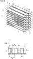
- heat exchanger 1 Although only one row of heat exchanger 1 is shown as disposed in heat exchanger 1 described above, multiple-row heat exchanger 1 including two or more rows of heat exchangers 1a, 1b, 1c and the like may be employed as shown in Fig. 16 . Such heat exchanger 1 can also be manufactured without a change in manufacturing method for each of heat exchangers 1a, 1b, 1c and the like.
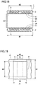
- FIG. 17 and 18 bellows-shaped corrugated fin 21 in heat exchanger 1 is bent such that planar portion 23 and a planar portion 26 are alternately formed. Planar portion 26 of corrugated fin 21 is bonded with adhesive 41 to flat tube 3.
- the configuration is otherwise similar to that of the heat exchanger shown in Figs. 3 to 6 , and thus the same components are designated by the same symbols and will not be described repeatedly unless necessary.
- the bonding strength can be further increased by the bonding of planar portion 26 to flat tube 3. This is now described.
- Fig. 19 shows a region where planar portion 26 faces flat tube 3.
- the length of this region in a direction in which flat tube 3 extends is represented as a length A1
- the length of this region in a direction orthogonal to the direction in which flat tube 3 extends is represented as a length B1.
- the length of this region in the direction in which flat tube 3 extends is length A1, which is equal to A1.
- the length of this region in the direction orthogonal to the direction in which flat tube 3 extends is a length B2 shorter than length B1, because the outer wall curved portion of flat tube 3 is located.
- curved portion 25 of corrugated fin 21 is bonded to flat tube 3 (see Fig. 3 ).
- the length of this region in the direction in which flat tube 3 extends is a length A2 shorter than length A1.
- length B2 is equal to length B2.
- a bonding area S1 between corrugated fin 21 and flat tube 3 is represented as A1 ⁇ A2.
- a bonding area S2 between corrugated fin 21 and flat tube 3 is represented as A2 ⁇ B2 (A2 ⁇ A1).
- bonding area S1 is larger than bonding area S2, so that the bonding strength can be improved.
- corrugated fin of the heat exchanger a corrugated fin capable of improving the bonding strength between the corrugated fin and the flat tube is described.
- bellows-shaped corrugated fin 21 in the heat exchanger is bent such that planar portion 23 and planar portion 26 are alternately formed.
- planar portion 26 is bonded with adhesive 41 to flat tube 3 in such a manner that adjacent planar portions 26 in corrugated fin 21 are located closest to each other.
- the configuration is otherwise similar to that of the heat exchanger shown in Figs. 3 to 6 , and thus the same components are designated by the same symbols and will not be described repeatedly unless necessary.
- Fig. 21 shows a region where planar portion 26 faces flat tube 3.
- the length of this region in the direction in which flat tube 3 extends is represented as length A1
- the length of this region in the direction orthogonal to the direction in which flat tube 3 extends is represented as length B1.
- length A2 of this region in the direction in which flat tube 3 extends is equal to length A1.
- the area of the region where planar portion 26 faces flat tube 3 is represented as A1 ⁇ B1.
- the bonding area of the region where planar portion 26 is bonded to flat tube 3 is represented as A1 ⁇ B2.
- Fig. 22 shows relation (graph) between the bonding area ratio, and shear stress acting on the bonding surface between the adhesive and the corrugated fin.
- shear stress at which a fin made of aluminum is fractured is 110 (N/mm 2 ).
- shear stress acting on adhesive 41 generally has a value lower than 6.9 (N/mm 2 ), which is the shear stress of an adhesive, so that corrugated fin 21 does not peel from adhesive 41.
- corrugated fin 21 of heat exchanger 1 described above, planar portions 26 are bonded with adhesive 41 to flat tube 3 in such a manner that adjacent planar portions 26 are located closest to each other.
- length A1 2 ⁇ fp.
- the bonding area between corrugated fin 21 and flat tube 3 can be increased, to further improve the bonding strength. Moreover, thermal resistance can be reduced. Furthermore, the thickness of adhesive 41 can be reduced, to reduce thermal resistance in a thickness direction of the adhesive. The amount of adhesive 41 used can also be reduced.
- flat tube 3 is provided with protrusions 15 in a direction intersecting a direction in which refrigerant flow path 5 extends.
- Corrugated fin 21 is provided with recesses 29 in which protrusions 15 of flat tube 3 fit.
- the configuration is otherwise similar to that of the heat exchanger shown in Figs. 3 to 6 , and thus the same components are designated by the same symbols and will not be described repeatedly unless necessary. It should be noted that protrusions 15 and recesses 29 are shown in an exaggerated manner for the purpose of illustration.
- flat tube 3 is provided with protrusions 15, and corrugated fin 21 is provided with recesses 29.
- a bonding distance (area) between corrugated fin 21 and flat tube 3 can be increased, thereby improving the bonding strength.
- This method is particularly effective when adhesive 41 susceptible to peeling in a direction of air flow is used as adhesive 41. At least one pair of protrusion 15 and recess 29 in the direction of air flow is enough to obtain a desired effect. In addition, the effect of suppressing the peeling of corrugated fin 21 is obtained even when the protruding length of protrusion 15 (the depth of recess 29) is not more than 1 mm.
- protrusions 15 have been described as provided at portions in a width direction of flat tube 3.
- the positions of the protrusions are not limited to such arrangement.
- protrusions 15 may be provided at one end side and the other end side in the width direction of flat tube 3, respectively, as shown in Fig. 24 .
- the effect of suppressing the peeling of corrugated fin 21 is obtained in this case as well.
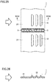
- corrugated fin 21 is provided with louvers 31.
- Double line arrows indicate a direction of air flow. Louvers 31 are disposed on the leeward side, and open toward the windward side.
- the configuration is otherwise similar to that of the heat exchanger shown in Figs. 3 to 6 , and thus the same components are designated by the same symbols and will not be described repeatedly unless necessary.
- heat exchange takes place when outdoor air (air) fed into a casing of the outdoor unit passes through a heat exchanger.
- outdoor air air
- an external force in the same direction as the direction of flow of the outside air tends to act on a corrugated fin.
- louvers are disposed on the windward side of the corrugated fin, there is a risk that the external force may break openings in the louvers to close the louvers, resulting in degradation in heat exchange performance.
- louvers 31 when louvers 31 are disposed on the leeward side, peel strength on the windward side on which the external force acts can be increased, as compared to an example where louvers 31 are disposed on the windward side, thereby suppressing the closing of louvers 31.
- the outside air can flow through louvers 31 to easily generate a turbulent flow, thereby further facilitating the heat exchange between the outside air and the refrigerant.
- Epoxy resin-based adhesive 41 has been described as an example of the bonding agent in each embodiment. Epoxy resin-based adhesive 41 has excellent heat resistance, water resistance, and stability to chemical materials. Moreover, epoxy resin-based adhesive 41 does not contain volatile organic chemical materials such as formaldehyde which has been identified as a cause of sick house syndrome. Epoxy resin-based adhesive 41 is therefore an adhesive suitable for a heat exchanger used for an indoor unit. Furthermore, epoxy resin-based adhesive 41 also has excellent oil resistance, and therefore can also be applied in a place where oil is frequently used such as a kitchen.
- Epoxy resin-based adhesives include a one-component adhesive and a two-component adhesive.
- a mixing ratio between epoxy resin and a curing agent may vary.
- a curing agent is added to epoxy resin in advance, so that stable bonding strength can be obtained without variation in components.
- epoxy resin-based adhesive 41 has a thermal conductivity (0.6 W/m ⁇ k) higher than the thermal conductivities (0.2 to 0.3 W/m ⁇ k) of other adhesives such as a nylon-based adhesive or polyester-based adhesive. It can be said also from this fact that epoxy resin-based adhesive 41 is an adhesive suitable for a heat exchanger.
- solder may be used, instead of epoxy resin-based adhesive 41, as the bonding agent.
- the solder may be formed on the surface of flat tube 3 by plating.
- corrugated fin 21 can be bonded with the solder to flat tube 3 under a temperature condition of two hundred and several tens of °C, and furthermore, coating material 27 coating corrugated fin 21 (see Fig. 4 ) does not melt.
- any bonding agent may be used other than the adhesive and the solder, as long as corrugated fin 21 (fin) and flat tube 3 (heat transfer tube) can be bonded together without causing melting of coating material 27 coating corrugated fin 21 (fin).
- corrugated fin 21 has been described as an example of the fin, a plate-like can also be applied.
- a clearance between the flat tube and the fin be set to a minimum value (5 ⁇ m) in order to suppress degradation in thermal conductivity caused by an increased thickness of the adhesive.
- the present invention is effectively utilized for a heat exchanger including a fin and a flat tube.
- 1, 1a, 1b, 1c heat exchanger 3 flat tube; 5 refrigerant flow path; 7 outer wall planar portion; 9 outer wall curved portion; 11 anticorrosive layer; 12 anticorrosive layer surface; 13 top; 15 protrusion; 21 corrugated fin; 23 planar portion; 25 curved portion; 26 planar portion; 27 coating material; 29 recess; 31 louver; 41 adhesive; 51 inlet side header; 53 outlet side header; 55 refrigerant inlet/outlet; 81 air conditioner; 83 compressor; 85 outdoor unit; 87 expansion valve; 89 indoor unit; 91 four-way valve; 93 outdoor fan; 95 indoor fan; 97 refrigerant pipe; A1, A2, B1, B2 length; fp fin pitch.
Landscapes
- Engineering & Computer Science (AREA)
- Mechanical Engineering (AREA)
- Physics & Mathematics (AREA)
- Thermal Sciences (AREA)
- General Engineering & Computer Science (AREA)
- Chemical & Material Sciences (AREA)
- Organic Chemistry (AREA)
- Materials Engineering (AREA)
- Metallurgy (AREA)
- Geometry (AREA)
- Heat-Exchange Devices With Radiators And Conduit Assemblies (AREA)
Abstract
Description
- The present invention relates to heat exchangers and methods of manufacturing thereof, and refrigeration cycle apparatuses, and more particularly to a heat exchanger having a fin bonded to a heat transfer tube, a method of manufacturing the heat exchanger, and a refrigeration cycle apparatus including such a heat exchanger.
- In one type of air conditioner such as a car air conditioner, a heat exchanger having a combination of a flat tube and a corrugated fin is used. The flat tube is a form of heat transfer tube through which refrigerant flows, which has a flat cross-sectional shape so as to achieve efficient heat transfer. The corrugated fin is a fin formed by bending a plate-like fin into a bellows shape.
- A plurality of flat tubes are spaced from one another in the minor axis direction of the flat tubes. Each of the plurality of flat tubes is disposed such that the major axis of the flat tube is along a direction of air flow. A plurality of corrugated fins are disposed such that one corrugated fin is disposed between one flat tube and another flat tube adjacent to and spaced from each other.
- Peak portions of a bellows-shaped fin facing one flat tube are joined to the one flat tube. Peak portions of the bellows-shaped fin facing another flat tube are joined to the another flat tube. The flat tubes and the bellows-shaped fin are conventionally joined by brazing. The brazing is performed under a relatively high temperature condition of approximately 600°C, for example.
-
- PTL 1: Japanese Patent Laying-Open No.
2016-130603 - PTL 2: Japanese Patent Laying-Open No.
2012-73014 - PTL 3: Japanese Patent Laying-Open No.
2003-1409 - PTL 4: Japanese Patent Laying-Open No.
2005-207728 - A heat exchanger is required, when dew adheres to its fin, to spread and discharge the dew to the outside of the heat exchanger without causing scattering of the dew. In particular, it is strongly required of a fin of an indoor heat exchanger not to cause scattering of dew into a room. It is also required that a surface of the fin not be contaminated. Accordingly, the surface of a fin including a corrugated fin is covered with a coating material having at least hydrophilic property and antifouling property.
- However, the coating material covering the surface of the fin melts by heat (approximately 600°C) during brazing. There have thus been proposed various methods of joining a fin to a flat tube while preventing a coating material from melting (
PTL 1, PTL 2,PTL 3 and PTL 4). - The present invention has been made as part of efforts to develop such a heat exchanger. An object of the present invention is to provide a heat exchanger having a flat tube and a fin bonded together, without causing melting of a coating material covering the fin. Another object is to provide a method of manufacturing such a heat exchanger. Yet another object is to provide a refrigeration cycle apparatus including such a heat exchanger.
- A heat exchanger according to the present invention includes a flat tube and a fin. The flat tube has a flat cross-sectional shape, and is covered with an anticorrosive layer. The fin is bonded to the flat tube with a bonding agent on a first surface of the anticorrosive layer interposed therebetween, and covered with a coating material. The first surface of the anticorrosive layer has been roughened. The bonding agent is fixed to the roughened first surface.
- A method of manufacturing a heat exchanger according to the present invention includes the following steps. A flat tube having a flat cross-sectional shape and covered with an anticorrosive layer is prepared. A fin covered with a coating material is prepared. A roughening process is performed on a first surface of the anticorrosive layer of the flat tube. A bonding agent is fixed to the first surface of the anticorrosive layer that has been subjected to the roughening process. The fin is brought into contact with the bonding agent. The fin is pressed toward the flat tube, while the flat tube is pressed toward the fin. Heat treatment is conducted while the flat tube and the fin are being pressed.
- A refrigeration cycle apparatus according to the present invention is a refrigeration cycle apparatus including the heat exchanger described above.
- According to the heat exchanger of the present invention, the fin is bonded to the flat tube with the bonding agent on the first surface of the anticorrosive layer interposed therebetween, so that the heat exchanger in which the coating material covering the fin does not melt is obtained.
- According to the method of manufacturing a heat exchanger of the present invention, the fin can be bonded to the flat tube without causing melting of the coating material covering the fin.
- According to the refrigeration cycle apparatus of the present invention, scattering of water droplets, soil or the like into a room can be suppressed by including the heat exchanger described above.
-
-
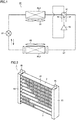
Fig. 1 shows a refrigerant circuit of an air conditioner including a heat exchanger according to each embodiment. -
Fig. 2 is a perspective view of the heat exchanger according to a first embodiment. -
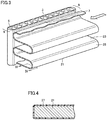
Fig. 3 is a partial enlarged perspective view showing a portion where a corrugated fin and a flat tube are bonded together in the same embodiment. -
Fig. 4 is a partial cross-sectional view of the corrugated fin taken along the cross-sectional line IV-IV shown inFig. 3 in the same embodiment. -
Fig. 5 is a side view including a partial cross section, showing the portion where the corrugated fin and the flat tube are bonded together in the same embodiment. -
Fig. 6 is a partial enlarged cross-sectional view inside a circle shown inFig. 5 in the same embodiment. -
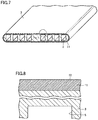
Fig. 7 is a partial perspective view including a partial cross section, showing a step of a method of manufacturing the heat exchanger shown inFig. 2 in the same embodiment. -
Fig. 8 is a partial enlarged cross-sectional view inside a circle shown inFig. 7 in the same embodiment. -
Fig. 9 is a partial perspective view including a partial cross section, showing a step performed after the step shown inFig. 7 in the same embodiment. -
Fig. 10 is a partial enlarged cross-sectional view inside a circle shown inFig. 9 in the same embodiment. -
Fig. 11 is a partial perspective view including a partial cross section, showing a step performed after the step shown inFig. 9 in the same embodiment. -
Fig. 12 is a partial enlarged cross-sectional view inside a circle shown inFig. 11 in the same embodiment. -
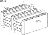
Fig. 13 is a partial perspective view including a partial cross section, showing a step performed after the step shown inFig. 11 in the same embodiment. -
Fig. 14 is a partial enlarged side view including a partial cross section of the step shown inFig. 13 in the same embodiment. -
Fig. 15 is a partial perspective view including a partial cross section, showing a step performed after the step shown inFig. 13 in the same embodiment. -
Fig. 16 is a perspective view showing an exemplary heat exchanger having a plurality of the heat exchangers shown inFig. 2 disposed therein in the same embodiment. -
Fig. 17 is a partial enlarged front view of a heat exchanger according to a second embodiment. -
Fig. 18 is a side view including a partial cross section, showing a portion where a corrugated fin and a flat tube are bonded together in the same embodiment. -
Fig. 19 is a partial plan view illustrating a region where the corrugated fin and the flat tube are bonded together in the same embodiment. -
Fig. 20 is a partial enlarged front view of a heat exchanger according to a third embodiment. -
Fig. 21 is a partial plan view illustrating a region where a corrugated fin and a flat tube are bonded together in the same embodiment. -
Fig. 22 is a graph showing relation between shear stress and a bonding area ratio in the same embodiment. -
Fig. 23 is a side view including a partial cross section, showing a portion where a corrugated fin and a flat tube are bonded together in a heat exchanger according to a fourth embodiment. -
Fig. 24 is a side view including a partial cross section, showing a portion where a corrugated fin and a flat tube are bonded together in a heat exchanger according to a modification in the same embodiment. -
Fig. 25 is a side view including a partial cross section, showing a portion where a corrugated fin and a flat tube are bonded together in a heat exchanger according to a fifth embodiment. -
Fig. 26 is a partial cross-sectional view of the corrugated fin taken along the cross-sectional line XXVI-XXVI shown inFig. 25 . - First, an air conditioner (refrigerant circuit) is described as an exemplary refrigeration cycle apparatus including a heat exchanger according to each embodiment. As shown in
Fig. 1 , anair conditioner 81 includes acompressor 83, a four-way valve 91, an indoor unit 89, anexpansion valve 87 and an outdoor unit 85.Compressor 83, four-way valve 91, indoor unit 89,expansion valve 87 and outdoor unit 85 are connected together by arefrigerant pipe 97. - Outdoor unit 85 includes a
heat exchanger 1 disposed therein. Outdoor unit 85 also includes anoutdoor fan 93 provided therein for forcibly feeding outdoor air intoheat exchanger 1. Heat exchange takes place between the outdoor air forcibly fed into and passing throughheat exchanger 1, and refrigerant flowing through heat exchanger 1 (flat tube). - Indoor unit 89 includes a
heat exchanger 1 disposed therein. Indoor unit 89 also include anindoor fan 95 provided therein for forcibly feeding indoor air intoheat exchanger 1. Heat exchange takes place between the indoor air forcibly fed into and passing throughheat exchanger 1, and refrigerant flowing through heat exchanger 1 (flat tube). - Operation of
air conditioner 81 includes cooling operation, heating operation and defrosting operation. The cooling operation is an operation for cooling the indoor air. The heating operation is an operation for heating the indoor air. The defrosting operation is an operation for melting frost and the like which have adhered toheat exchanger 1 of outdoor unit 85. - In
air conditioner 81, a refrigerant flow path is switched by four-way valve 91 depending on the cooling operation, the heating operation and the defrosting operation. In the cooling operation and the defrosting operation, the refrigerant discharged fromcompressor 83 is fed into outdoor unit 85 (heat exchanger 1), and the refrigerant that has flown through indoor unit 89 (heat exchanger 1) is returned to compressor 83 (see dotted line arrows). In the heating operation, on the other hand, the refrigerant discharged fromcompressor 83 is fed into indoor unit 89 (heat exchanger 1), and the refrigerant that has flown through outdoor unit 85 (heat exchanger 1) is returned to compressor 83 (see solid line arrows). - Each operation is described in further detail. First, in the cooling operation,
heat exchanger 1 of outdoor unit 85 serves as a condenser, andheat exchanger 1 of indoor unit 89 serves as an evaporator. By drivingcompressor 83, high-temperature and high-pressure gaseous refrigerant is discharged fromcompressor 83. The discharged high-temperature and high-pressure gas refrigerant (single phase) flows through four-way valve 91 intoheat exchanger 1 of outdoor unit 85. In thatheat exchanger 1, heat exchange takes place between the refrigerant that has flown therein and the air fed into outdoor unit 85, causing the high-temperature and high-pressure gas refrigerant to condense into high-pressure liquid refrigerant (single phase). - The high-pressure liquid refrigerant fed from outdoor unit 85 (heat exchanger 1) is turned, by
expansion valve 87, into refrigerant in a two-phase state of low-pressure gas refrigerant and liquid refrigerant. The refrigerant in a two-phase state flows intoheat exchanger 1 of indoor unit 89. In thatheat exchanger 1, heat exchange takes place between the refrigerant in a two-phase state that has flown therein and the air fed into indoor unit 89, causing the refrigerant in a two-phase state into low-pressure gas refrigerant (single phase) due to evaporation of its liquid refrigerant. The room interior is cooled by this heat exchange. The low-pressure gas refrigerant fed from indoor unit 89 (heat exchanger 1) flows through four-way valve 91 intocompressor 83. The low-pressure gas refrigerant that has flown therein is compressed into high-temperature and high-pressure gas refrigerant, and discharged fromcompressor 83 again. This cycle is repeated thereafter. - Next, in the heating operation,
heat exchanger 1 of outdoor unit 85 serves as an evaporator, andheat exchanger 1 of indoor unit 89 serves as a condenser. By drivingcompressor 83, high-temperature and high-pressure gaseous refrigerant is discharged fromcompressor 83. The discharged high-temperature and high-pressure gas refrigerant (single phase) flows through four-way valve 91 intoheat exchanger 1 of indoor unit 89. In thatheat exchanger 1, heat exchange takes place between the gas refrigerant that has flown therein and the air fed into indoor unit 89, causing the high-temperature and high-pressure gas refrigerant to condense into high-pressure liquid refrigerant (single phase). The room interior is heated by this heat exchange. - The high-pressure liquid refrigerant fed from indoor unit 89 (heat exchanger 1) is turned, by
expansion valve 87, into refrigerant in a two-phase state of low-pressure gas refrigerant and liquid refrigerant. The refrigerant in a two-phase state flows intoheat exchanger 1 of outdoor unit 85. In thatheat exchanger 1, heat exchange takes place between the refrigerant in a two-phase state that has flown therein and the air fed into outdoor unit 85, causing the refrigerant in a two-phase state into low-pressure gas refrigerant (single phase) due to evaporation of its liquid refrigerant. The low-pressure gas refrigerant fed from outdoor unit 85 (heat exchanger 1) flows through four-way valve 91 intocompressor 83. The low-pressure gas refrigerant that has flown therein is compressed into high-temperature and high-pressure gas refrigerant, and discharged fromcompressor 83 again. This cycle is repeated thereafter. - In this heating operation, since
heat exchanger 1 of outdoor unit 85 serves as an evaporator, moisture contained in the outdoor air may turn into frost and adhere toheat exchanger 1. Once the frost has adhered toheat exchanger 1 of outdoor unit 85, a flow of the outdoor air trying to pass through thatheat exchanger 1 is hindered. Thus, satisfactory heat exchange between the outdoor air and the refrigerant flowing throughheat exchanger 1 is not performed, resulting in degraded heating efficiency ofair conditioner 81. To avoid this, inair conditioner 81, once frost has adhered toheat exchanger 1 of outdoor unit 85 to a level equal to or above a certain level, the heating operation is suspended, and the defrosting operation is performed for melting the frost that has adhered toheat exchanger 1. - In the defrosting operation, the actions of
outdoor fan 93 andindoor fan 95 are stopped. A flow of the refrigerant in the defrosting operation is the same as the flow of the refrigerant in the cooling operation. When the defrosting operation is started, high-temperature and high-pressure gaseous refrigerant discharged fromcompressor 83 is fed through four-way valve 91 intoheat exchanger 1 of outdoor unit 85. In thatheat exchanger 1, heat of the gaseous refrigerant is dissipated, causing the frost that has adhered toheat exchanger 1 to melt. Subsequently, the refrigerant flows from outdoor unit 85 toexpansion valve 87 and indoor unit 89, and is returned tocompressor 83. This cycle is repeated thereafter until the frost that has adhered toheat exchanger 1 is removed. - Next, the structure of
heat exchanger 1 disposed in each of indoor unit 89 and outdoor unit 85 is described. - As shown in
Figs. 2 and3 ,heat exchanger 1 includes a plurality of flat tubes 3 (heat transfer tubes), a plurality of corrugated fins 21 (fins), aninlet side header 51 and anoutlet side header 53. The plurality offlat tubes 3 are substantially horizontally disposed, and are vertically spaced from one another. Eachflat tube 3 is provided with an outer wallplanar portion 7 and an outer wall curvedportion 9. A plurality ofrefrigerant flow paths 5 through which the refrigerant flows are formed at a distance from one another withinflat tube 3. -
Inlet side header 51 is disposed at one end side in a longitudinal direction of the plurality offlat tubes 3, andoutlet side header 53 is disposed at the other end side in the longitudinal direction.Inlet side header 51 is provided with a refrigerant inlet/outlet 55.Outlet side header 53 is provided with a refrigerant inlet/outlet 55. For example, the refrigerant that has flown in through refrigerant inlet/outlet 55 ofinlet side header 51 flows throughflat tubes 3 and is transferred tooutlet side header 53. The refrigerant that has flown in through refrigerant inlet/outlet 55 ofoutlet side header 53, on the other hand, flows throughflat tubes 3 and is transferred toinlet side header 51. - Each
corrugated fin 21 is disposed between oneflat tube 3 and anotherflat tube 3 vertically adjacent to each other.Corrugated fin 21 is a fin formed by bending a plate-like fin into a bellows shape. Here,corrugated fin 21 has acurved portion 25 and aplanar portion 23. As shown inFig. 4 , the surface ofcorrugated fin 21 is covered with acoating material 27 having at least hydrophilic property and antifouling property. - As shown in
Figs. 3 and5 , a peak portion (curved portion 25) ofcorrugated fin 21 facing oneflat tube 3 is bonded with an adhesive 41 to outer wallplanar portion 7 of the oneflat tube 3. A peak portion (curved portion 25) ofcorrugated fin 21 facing anotherflat tube 3 is bonded with adhesive 41 to outer wallplanar portion 7 of the anotherflat tube 3. Here, an epoxy-based adhesive is applied, for example, as adhesive 41. - As shown in
Fig. 6 ,flat tube 3 is covered with ananticorrosive layer 11 made of an alloy layer of aluminum and zinc, for example. The surface ofanticorrosive layer 11 has been subjected to a roughening process. Roughenedanticorrosive layer 11 has an arithmetic mean roughness of not less than 0.7 µm and not more than 100 µm. When the arithmetic mean roughness is lower than 0.7 µm, adequate bonding strength betweenadhesive 41 and flat tube 3 (anticorrosive layer 11) cannot be obtained. On the other hand, sinceanticorrosive layer 11 has an initial thickness of approximately 100 µm, when the arithmetic mean roughness exceeds 100 µm,anticorrosive layer 11 will be penetrated, thus increasing the possibility of corrosion offlat tube 3. - A distance TH from the top of the roughened surface of
anticorrosive layer 11 to an upper surface of adhesive 41 (the thickness of adhesive 41) is not less than 0.1 µm and not more than 5.0 µm. When the thickness of adhesive 41 is smaller than 0.1 µm, it is difficult to control the distribution (thickness) of adhesive 41 applied toflat tube 3, possibly resulting in variation in bonding state after the bonding. When the thickness of adhesive 41 exceeds 5.0 µm, on the other hand, thermal conduction betweenflat tube 3 andcorrugated fin 21 is more likely to be hindered. There is also a risk of an outflow of the adhesive during the bonding.Heat exchanger 1 according to the first embodiment is configured as described above. - Next, an exemplary method of
manufacturing heat exchanger 1 described above is described. First,flat tube 3 is prepared as shown inFigs. 7 and 8 . The surface offlat tube 3 is covered withanticorrosive layer 11.Anticorrosive layer 11 has a thickness of approximately 100 µm. At this point in time, ananticorrosive layer surface 12 has an arithmetic mean surface roughness of approximately between 0.2 µm and 0.5 µm. - Next, a blasting process is performed on
flat tube 3. As shown inFigs. 9 and 10 , fine sand is sprayed ontoflat tube 3 to thereby roughenanticorrosive layer surface 12 located at outer wallplanar portion 7. Here,anticorrosive layer surface 12 is roughened so as to have an arithmetic mean surface roughness of not less than 0.7 µm and not more than 100 µm. - Next, as shown in
Figs. 11 and 12 , adhesive 41 is applied (cladding) to the surface (outer wall planar portion 7) offlat tube 3 that has been subjected to the blasting process. Here, the adhesive is applied such that the distance from the top of roughenedanticorrosive layer surface 12 to the upper surface of adhesive 41 (the thickness of adhesive 41) is approximately 5 µm. The adhesive is applied by spraying adhesive 41 ontoflat tube 3, for example. Alternatively, adhesive 41 may be applied toflat tube 3 by a roll (not shown). - Next,
flat tubes 3 andcorrugated fins 21 are bonded together. As shown inFigs. 13 and14 , the plurality offlat tubes 3 and the plurality ofcorrugated fins 21 are disposed in such a manner that eachcorrugated fin 21 is sandwiched between oneflat tube 3 and anotherflat tube 3 spaced from and adjacent to each other. Then, in this state, wires (not shown) are tied, for example, around the plurality offlat tubes 3 and the plurality ofcorrugated fins 21, to apply pressure in a direction in which corrugatedfin 21 is sandwiched between the oneflat tube 3 and the another flat tube 3 (see arrows). - Next, heat treatment is conducted under a temperature condition of approximately 200°C (see wavy line arrows), while the pressure is being applied to the plurality of
flat tubes 3 and the plurality ofcorrugated fins 21. As a result,corrugated fins 21 andflat tubes 3 are bonded together with adhesive 41, whilecorrugated fins 21 andflat tubes 3 are in close contact with each other. Here, since the temperature for the heat treatment is approximately 200°C, coatingmaterial 27 coveringcorrugated fin 21 does not melt, so that the hydrophilic property, antifouling property and the like ofcorrugated fin 21 are maintained. - The wires (not shown) are subsequently untied, to complete
heat exchanger 1 havingflat tubes 3 andcorrugated fins 21 bonded together with adhesive 41 (seeFig. 2 ). - In
heat exchanger 1 described above, first,anticorrosive layer 11 offlat tube 3 is subjected to the roughening process, and then adhesive 41 is sprayed onto or applied to the roughened surface ofanticorrosive layer 11, to thereby fix adhesive 41 to flat tube 3 (cladding). Here, the thickness of adhesive 41 (distance TH from the top of the roughened surface ofanticorrosive layer 11 to the upper surface of adhesive 41) is at least not less than 0.1 µm. As a result, a uniform distribution (thickness) of adhesive 41 applied toflat tube 3 can be achieved. - Next, the heat treatment is conducted while pressure is being applied such that
corrugated fin 21 is sandwiched between oneflat tube 3 and anotherflat tube 3, to thereby bondflat tubes 3 andcorrugated fin 21 together whilecorrugated fin 21 is in reliable contact with adhesive 41. As a result, a bonding ratio offlat tubes 3 andcorrugated fins 21 can be improved. The bonding ratio means a ratio of the number of actual bonding portions to the number of all bonding portions. -
Adhesive 41 has a lower melting point than base materials forflat tube 3 andcorrugated fin 21. In addition, adhesive 41 is not diffused into these base materials and does not form a metallic bond, and therefore tends to have lower bonding power than common brazing. - In the method described above, adhesive 41 can be reliably fixed to the roughened surface of
flat tube 3, and the bonding ratio of bondingcorrugated fin 21 bonded to adhesive 41 reliably fixed toflat tube 3 can be increased, to thereby improve the bonding strength betweencorrugated fin 21 andflat tube 3. In addition, bonding failure during the manufacture ofheat exchanger 1 can be suppressed to improve the productivity, thus contributing to reduction in production costs. - As described above, generally, a fin of a heat exchanger of an air conditioner is required to have hydrophilic property and antifouling property. The surface of
corrugated fin 21 is covered withcoating material 27 having hydrophilic property, antifouling property and the like.Coating material 27 will melt under a temperature condition (approximately 600°C) when a corrugated fin and a flat tube are joined together by brazing. - On the other hand, the temperature for the heat treatment when corrugated
fin 21 andflat tube 3 are bonded together with adhesive 41 is approximately 200°C. Accordingly, coatingmaterial 27 will not melt, and the hydrophilic property, antifouling property and the like ofcorrugated fin 21 can be maintained. - When a corrugated fin and a flat tube are to be joined together by brazing, a process of covering the corrugated fin with a coating material is performed after the brazing.
- In this case, the coating material needs to be uniformly applied to the corrugated fin, with the corrugated fin being bonded to the flat tube. However, it is difficult to uniformly apply the coating material to the corrugated fin due to limited viscosity of the coating material, resulting in degradation in performance such as hydrophilic property and antifouling property as compared to a corrugated fin covered with a coating material before the bonding.
- Particularly, in the case of a heat exchanger of an indoor unit, degradation in hydrophilic property of the surface of a corrugated fin may cause water droplets produced during dehumidification to be detached from the corrugated fin, resulting in the water droplets dropping in a room. Particularly, in the case of a corrugated fin, a heat exchanger has fins arranged in a bellows shape at high density, causing an increase in the amount of water droplets held due to an increase in surface tension. Thus, the water droplets that have adhered to the corrugated fin are more likely to drop in a room.
- In the case of a heat exchanger of an outdoor unit, on the other hand, degradation in hydrophilic property of the surface of a corrugated fin may cause degradation in drainage performance during defrosting operation. Thus, heating performance sometimes cannot be fully utilized when the defrosting operation is switched to the heating operation. Moreover, water droplets remaining on the corrugated fin may freeze into ice, in which case the heat exchanger may be damaged. The manufacturing method according to the first embodiment can avoid such problems.
- Although only one row of
heat exchanger 1 is shown as disposed inheat exchanger 1 described above, multiple-row heat exchanger 1 including two or more rows ofheat exchangers Fig. 16 .Such heat exchanger 1 can also be manufactured without a change in manufacturing method for each ofheat exchangers - Here, an exemplary modification of the corrugated fin of the heat exchanger is described. As shown in
Figs. 17 and18 , bellows-shapedcorrugated fin 21 inheat exchanger 1 is bent such thatplanar portion 23 and aplanar portion 26 are alternately formed.Planar portion 26 ofcorrugated fin 21 is bonded with adhesive 41 toflat tube 3. The configuration is otherwise similar to that of the heat exchanger shown inFigs. 3 to 6 , and thus the same components are designated by the same symbols and will not be described repeatedly unless necessary. - In
corrugated fin 21 of the heat exchanger described above, the bonding strength can be further increased by the bonding ofplanar portion 26 toflat tube 3. This is now described. -
Fig. 19 shows a region whereplanar portion 26 facesflat tube 3. Here, with regard to the region whereplanar portion 26 facesflat tube 3, the length of this region in a direction in whichflat tube 3 extends is represented as a length A1, and the length of this region in a direction orthogonal to the direction in whichflat tube 3 extends is represented as a length B1. Then, with regard to a region whereplanar portion 26 is bonded toflat tube 3, the length of this region in the direction in whichflat tube 3 extends is length A1, which is equal to A1. On the other hand, the length of this region in the direction orthogonal to the direction in whichflat tube 3 extends is a length B2 shorter than length B1, because the outer wall curved portion offlat tube 3 is located. - In contrast, in
heat exchanger 1 according to the first embodiment,curved portion 25 ofcorrugated fin 21 is bonded to flat tube 3 (seeFig. 3 ). Thus, with regard to a region wherecurved portion 25 is bonded toflat tube 3, the length of this region in the direction in whichflat tube 3 extends is a length A2 shorter than length A1. On the other hand, the length of this region in the direction orthogonal to the direction in whichflat tube 3 extends is length B2, which is equal to length B2. - Accordingly, in
heat exchanger 1 according to the second embodiment, a bonding area S1 betweencorrugated fin 21 andflat tube 3 is represented as A1 × A2. - In
heat exchanger 1 according to the first embodiment, on the other hand, a bonding area S2 betweencorrugated fin 21 andflat tube 3 is represented as A2×B2 (A2<A1). As a result, bonding area S1 is larger than bonding area S2, so that the bonding strength can be improved. - Here, as another exemplary modification of the corrugated fin of the heat exchanger, a corrugated fin capable of improving the bonding strength between the corrugated fin and the flat tube is described.
- As shown in
Fig. 20 , bellows-shapedcorrugated fin 21 in the heat exchanger is bent such thatplanar portion 23 andplanar portion 26 are alternately formed. In particular,planar portion 26 is bonded with adhesive 41 toflat tube 3 in such a manner that adjacentplanar portions 26 incorrugated fin 21 are located closest to each other. The configuration is otherwise similar to that of the heat exchanger shown inFigs. 3 to 6 , and thus the same components are designated by the same symbols and will not be described repeatedly unless necessary. - Next, the bonding strength between
corrugated fin 21 andflat tube 3 is described.Fig. 21 shows a region whereplanar portion 26 facesflat tube 3. Here, with regard to the region whereplanar portion 26 facesflat tube 3, the length of this region in the direction in whichflat tube 3 extends is represented as length A1, and the length of this region in the direction orthogonal to the direction in whichflat tube 3 extends is represented as length B1. - Then, with regard to a region where
planar portion 26 is bonded toflat tube 3, length A2 of this region in the direction in whichflat tube 3 extends is equal to length A1. On the other hand, the length of this region in the direction orthogonal to the direction in whichflat tube 3 extends is length B2 shorter than length B1, because the outer wall curved portion offlat tube 3 is located. - The area of the region where
planar portion 26 facesflat tube 3 is represented as A1×B1. The bonding area of the region whereplanar portion 26 is bonded toflat tube 3 is represented as A1×B2. When a ratio of the bonding area of the region whereplanar portion 26 is bonded toflat tube 3 to the area of the region whereplanar portion 26 facesflat tube 3 is referred to as a bonding area ratio, then the bonding area ratio is represented as (A1×B2)/(A1×B1) = B2/B1. - Here,
Fig. 22 shows relation (graph) between the bonding area ratio, and shear stress acting on the bonding surface between the adhesive and the corrugated fin. It is known that shear stress at which a fin made of aluminum is fractured is 110 (N/mm2). According to evaluation by the inventors, it was found that, when the bonding area ratio is not less than approximately 0.8, even when a shear stress of 110 (N/mm2) occurs in a direction of air flow, shear stress acting on adhesive 41 generally has a value lower than 6.9 (N/mm2), which is the shear stress of an adhesive, so thatcorrugated fin 21 does not peel from adhesive 41. - Moreover, in
corrugated fin 21 ofheat exchanger 1 described above,planar portions 26 are bonded with adhesive 41 toflat tube 3 in such a manner that adjacentplanar portions 26 are located closest to each other. Thus, when a fin pitch ofcorrugated fin 21 is represented as fp, length A1 is represented as: length A1 = 2·fp. - Accordingly, as compared to the heat exchanger described in the second embodiment (see
Fig. 17 ), the bonding area betweencorrugated fin 21 andflat tube 3 can be increased, to further improve the bonding strength. Moreover, thermal resistance can be reduced. Furthermore, the thickness of adhesive 41 can be reduced, to reduce thermal resistance in a thickness direction of the adhesive. The amount of adhesive 41 used can also be reduced. - Here, a modification of the corrugated fin and the flat tube is described. As shown in
Fig. 23 ,flat tube 3 is provided withprotrusions 15 in a direction intersecting a direction in whichrefrigerant flow path 5 extends.Corrugated fin 21, on the other hand, is provided withrecesses 29 in which protrusions 15 offlat tube 3 fit. The configuration is otherwise similar to that of the heat exchanger shown inFigs. 3 to 6 , and thus the same components are designated by the same symbols and will not be described repeatedly unless necessary. It should be noted thatprotrusions 15 and recesses 29 are shown in an exaggerated manner for the purpose of illustration. - In the heat exchanger described above,
flat tube 3 is provided withprotrusions 15, andcorrugated fin 21 is provided withrecesses 29. Thus, as compared to a heat exchanger not provided with such protrusions and recesses, a bonding distance (area) betweencorrugated fin 21 andflat tube 3 can be increased, thereby improving the bonding strength. - This method is particularly effective when adhesive 41 susceptible to peeling in a direction of air flow is used as adhesive 41. At least one pair of
protrusion 15 andrecess 29 in the direction of air flow is enough to obtain a desired effect. In addition, the effect of suppressing the peeling ofcorrugated fin 21 is obtained even when the protruding length of protrusion 15 (the depth of recess 29) is not more than 1 mm. - In the heat exchanger described above,
protrusions 15 have been described as provided at portions in a width direction offlat tube 3. The positions of the protrusions are not limited to such arrangement. For example,protrusions 15 may be provided at one end side and the other end side in the width direction offlat tube 3, respectively, as shown inFig. 24 . The effect of suppressing the peeling ofcorrugated fin 21 is obtained in this case as well. - Here, a modification of the corrugated fin is described. As shown in
Figs. 25 and 26 ,corrugated fin 21 is provided withlouvers 31. Double line arrows indicate a direction of air flow.Louvers 31 are disposed on the leeward side, and open toward the windward side. The configuration is otherwise similar to that of the heat exchanger shown inFigs. 3 to 6 , and thus the same components are designated by the same symbols and will not be described repeatedly unless necessary. - Generally, in an outdoor unit of an air conditioner, heat exchange takes place when outdoor air (air) fed into a casing of the outdoor unit passes through a heat exchanger. When the outside air is passing through the heat exchanger, an external force in the same direction as the direction of flow of the outside air tends to act on a corrugated fin. When louvers are disposed on the windward side of the corrugated fin, there is a risk that the external force may break openings in the louvers to close the louvers, resulting in degradation in heat exchange performance.
- In contrast, when
louvers 31 are disposed on the leeward side, peel strength on the windward side on which the external force acts can be increased, as compared to an example wherelouvers 31 are disposed on the windward side, thereby suppressing the closing oflouvers 31. Thus, the outside air can flow throughlouvers 31 to easily generate a turbulent flow, thereby further facilitating the heat exchange between the outside air and the refrigerant. - Epoxy resin-based
adhesive 41 has been described as an example of the bonding agent in each embodiment. Epoxy resin-basedadhesive 41 has excellent heat resistance, water resistance, and stability to chemical materials. Moreover, epoxy resin-basedadhesive 41 does not contain volatile organic chemical materials such as formaldehyde which has been identified as a cause of sick house syndrome. Epoxy resin-basedadhesive 41 is therefore an adhesive suitable for a heat exchanger used for an indoor unit. Furthermore, epoxy resin-basedadhesive 41 also has excellent oil resistance, and therefore can also be applied in a place where oil is frequently used such as a kitchen. - Epoxy resin-based adhesives include a one-component adhesive and a two-component adhesive. In the two-component adhesive, a mixing ratio between epoxy resin and a curing agent may vary. In the one-component adhesive, on the other hand, a curing agent is added to epoxy resin in advance, so that stable bonding strength can be obtained without variation in components.
- In addition, epoxy resin-based
adhesive 41 has a thermal conductivity (0.6 W/m·k) higher than the thermal conductivities (0.2 to 0.3 W/m·k) of other adhesives such as a nylon-based adhesive or polyester-based adhesive. It can be said also from this fact that epoxy resin-basedadhesive 41 is an adhesive suitable for a heat exchanger. - Alternatively, solder may be used, instead of epoxy resin-based
adhesive 41, as the bonding agent. In the case of solder, the solder may be formed on the surface offlat tube 3 by plating. In the case of solder,corrugated fin 21 can be bonded with the solder toflat tube 3 under a temperature condition of two hundred and several tens of °C, and furthermore,coating material 27 coating corrugated fin 21 (seeFig. 4 ) does not melt. - Moreover, any bonding agent may be used other than the adhesive and the solder, as long as corrugated fin 21 (fin) and flat tube 3 (heat transfer tube) can be bonded together without causing melting of
coating material 27 coating corrugated fin 21 (fin). - Although
corrugated fin 21 has been described as an example of the fin, a plate-like can also be applied. In this case, it is desirable that a clearance between the flat tube and the fin be set to a minimum value (5 µm) in order to suppress degradation in thermal conductivity caused by an increased thickness of the adhesive. - The heat exchangers described in the respective embodiments can be combined in various ways as needed.
- The embodiments disclosed herein are illustrative and non-restrictive. The present invention is defined by the terms of the claims, not the description above, and is intended to include any modifications within the meaning and scope equivalent to the terms of the claims.
- The present invention is effectively utilized for a heat exchanger including a fin and a flat tube.
- 1, 1a, 1b, 1c heat exchanger; 3 flat tube; 5 refrigerant flow path; 7 outer wall planar portion; 9 outer wall curved portion; 11 anticorrosive layer; 12 anticorrosive layer surface; 13 top; 15 protrusion; 21 corrugated fin; 23 planar portion; 25 curved portion; 26 planar portion; 27 coating material; 29 recess; 31 louver; 41 adhesive; 51 inlet side header; 53 outlet side header; 55 refrigerant inlet/outlet; 81 air conditioner; 83 compressor; 85 outdoor unit; 87 expansion valve; 89 indoor unit; 91 four-way valve; 93 outdoor fan; 95 indoor fan; 97 refrigerant pipe; A1, A2, B1, B2 length; fp fin pitch.
Claims (17)
- A heat exchanger comprising:a flat tube having a flat cross-sectional shape and covered with an anticorrosive layer; anda fin bonded to the flat tube with a bonding agent on a first surface of the anticorrosive layer interposed therebetween, and covered with a coating material,the first surface of the anticorrosive layer having been roughened, andthe bonding agent being fixed to the roughened first surface.
- The heat exchanger according to claim 1, wherein
the first surface of the anticorrosive layer has been roughened so as to have an arithmetic mean surface roughness of not less than 0.7 µm and not more than 100 µm. - The heat exchanger according to claim 2, wherein
a thickness of the bonding agent from a top of the roughened first surface of the anticorrosive layer to an upper surface of the bonding agent is not less than 0.1 µm and not more than 5.0 µm. - The heat exchanger according to any one of claims 1 to 3, wherein
the fin includes a portion extending as a flat plate along the flat tube, and
the portion extending as a flat plate is bonded to the flat tube. - The heat exchanger according to any one of claims 1 to 4, wherein
the flat tube has a width in a first direction, and extends in a second direction intersecting the first direction, and
when a length in the second direction over which the fin and the flat tube are in contact with each other is represented as a length A1, a length in the second direction of a portion where the fin and the flat tube are bonded together with the bonding agent is represented as a length A2, a length in the first direction over which the fin and the flat tube are in contact with each other is represented as a length B1, a length in the first direction of the portion where the fin and the flat tube are bonded together with the bonding agent is represented as a length B2, and a bonding area ratio is represented as (A2×B2)/(A1×B1), then the bonding area ratio is greater than 0.8. - The heat exchanger according to any one of claims 1 to 5, wherein
the flat tube is provided with a first protrusion-recess portion, and
the fin is provided with a second protrusion-recess portion in which the first protrusion-recess portion fits. - The heat exchanger according to any one of claims 1 to 6, wherein
the fin is provided with a louver located on a leeward side. - The heat exchanger according to any one of claims 1 to 7, wherein
the bonding agent includes an adhesive. - The heat exchanger according to claim 8, wherein
the adhesive includes an epoxy resin-based adhesive. - The heat exchanger according to any one of claims 1 to 7, wherein
the bonding agent includes solder. - A method of manufacturing a heat exchanger, comprising:preparing a flat tube having a flat cross-sectional shape and covered with an anticorrosive layer;preparing a fin covered with a coating material;performing a roughening process on a first surface of the anticorrosive layer of the flat tube;fixing a bonding agent to the first surface of the anticorrosive layer that has been subjected to the roughening process;bringing the fin into contact with the bonding agent;pressing the fin toward the flat tube, while pressing the flat tube toward the fin; andconducting heat treatment while the flat tube and the fin are being pressed.
- The method of manufacturing a heat exchanger according to claim 11, wherein
in the performing a roughening process, the first surface is roughened so as to have an arithmetic mean surface roughness of not less than 0.7 µm and not more than 100 µm. - The method of manufacturing a heat exchanger according to claim 11 or 12, wherein
in the conducting heat treatment, the heat treatment is conducted under a temperature condition lower than a temperature at which the coating material melts. - The method of manufacturing a heat exchanger according to any one of claims 11 to 13, wherein
in the fixing a bonding agent, an adhesive is used as the bonding agent. - The method of manufacturing a heat exchanger according to claim 14, wherein
in the fixing a bonding agent, an epoxy resin-based adhesive is used as the adhesive. - The method of manufacturing a heat exchanger according to any one of claims 11 to 13, wherein
in the fixing a bonding agent, solder is used as the bonding agent, and the solder is fixed to the flat tube by plating. - A refrigeration cycle apparatus comprising the heat exchanger according to any one of claims 1 to 10.
Applications Claiming Priority (1)
| Application Number | Priority Date | Filing Date | Title |
|---|---|---|---|
| PCT/JP2016/088115 WO2018116408A1 (en) | 2016-12-21 | 2016-12-21 | Heat exchanger, method for manufacturing same, and refrigeration cycle device |
Publications (3)
| Publication Number | Publication Date |
|---|---|
| EP3561434A1 true EP3561434A1 (en) | 2019-10-30 |
| EP3561434A4 EP3561434A4 (en) | 2019-12-25 |
| EP3561434B1 EP3561434B1 (en) | 2023-03-29 |
Family
ID=62626059
Family Applications (1)
| Application Number | Title | Priority Date | Filing Date |
|---|---|---|---|
| EP16924289.8A Active EP3561434B1 (en) | 2016-12-21 | 2016-12-21 | Heat exchanger, method for manufacturing same, and refrigeration cycle device |
Country Status (5)
| Country | Link |
|---|---|
| US (2) | US11499210B2 (en) |
| EP (1) | EP3561434B1 (en) |
| JP (1) | JP6768834B2 (en) |
| CN (1) | CN110073167B (en) |
| WO (1) | WO2018116408A1 (en) |
Families Citing this family (11)
| Publication number | Priority date | Publication date | Assignee | Title |
|---|---|---|---|---|
| CN113720174B (en) | 2019-05-05 | 2024-12-17 | 浙江三花智能控制股份有限公司 | Microchannel heat exchanger |
| CN114754606B (en) * | 2021-01-08 | 2023-08-11 | 杭州三花研究院有限公司 | Heat exchanger and its preparation method |
| BR112023018455A2 (en) * | 2021-03-19 | 2023-10-10 | Brazeway Inc | MICROCHANNEL HEAT EXCHANGER FOR APPLIANCE CONDENSER |
| US12405070B2 (en) * | 2022-01-04 | 2025-09-02 | Carrier Corporation | Corrosion resistant microchannel heat exchanger |
| CN115325854B (en) * | 2022-07-01 | 2024-04-16 | 杭州三花研究院有限公司 | Heat exchanger and method for manufacturing the same |
| CN115325851B (en) * | 2022-07-01 | 2024-04-12 | 杭州三花研究院有限公司 | Heat exchanger and method for manufacturing the same |
| CN115325853B (en) * | 2022-07-01 | 2024-04-12 | 杭州三花研究院有限公司 | Heat exchanger and method for manufacturing the same |
| WO2024002119A1 (en) * | 2022-07-01 | 2024-01-04 | 杭州三花研究院有限公司 | Heat exchanger and manufacturing method therefor |
| CN115325852B (en) * | 2022-07-01 | 2024-04-16 | 杭州三花研究院有限公司 | Heat exchanger and method for manufacturing the same |
| KR20240121008A (en) * | 2023-02-01 | 2024-08-08 | 엘지전자 주식회사 | Heat exchanger |
| WO2025154508A1 (en) * | 2024-01-17 | 2025-07-24 | 株式会社デンソー | Heat exchanger and method for manufacturing heat exchanger |
Family Cites Families (54)
| Publication number | Priority date | Publication date | Assignee | Title |
|---|---|---|---|---|
| US3731732A (en) * | 1971-05-03 | 1973-05-08 | Modine Manuf | Tube and fin heat exchanger |
| JPS58148485U (en) * | 1982-03-27 | 1983-10-05 | カルソニックカンセイ株式会社 | Heat exchanger |
| JPS59191892A (en) * | 1983-04-13 | 1984-10-31 | Nippon Denso Co Ltd | Heat exchanger assembled without soldering |
| US4714623A (en) * | 1985-02-28 | 1987-12-22 | Riccio Louis M | Method and apparatus for applying metal cladding on surfaces and products formed thereby |
| US5305945A (en) * | 1989-09-12 | 1994-04-26 | Modine Manufacturing Co. | Finned assembly for heat exchangers |
| US5295302A (en) * | 1991-10-29 | 1994-03-22 | Calsonic Corporation | Method of manufacturing an aluminum heat exchanger |
| JPH06221787A (en) | 1993-01-29 | 1994-08-12 | Nippondenso Co Ltd | Heat exchanger |
| US5490559A (en) * | 1994-07-20 | 1996-02-13 | Dinulescu; Horia A. | Heat exchanger with finned partition walls |
| EP0823296A3 (en) * | 1996-08-03 | 2000-03-01 | Balcke-Dürr GmbH | Method of manufacturing corrosion resistant heat exchangers |
| JPH10246592A (en) * | 1997-03-07 | 1998-09-14 | Furukawa Electric Co Ltd:The | Extruded flat multi-hole tube for brazing member of heat exchanger and method of manufacturing the same |
| DE69808565T2 (en) * | 1997-07-16 | 2003-02-13 | Denso Corp., Kariya | Aluminum alloy tube and heat exchanger, and method for metal spraying a filler metal |
| EP0907064A3 (en) * | 1997-10-03 | 2000-08-02 | Horia A. Dinulescu | Heat exchanger, more particularly air cooler for power plant, and method for manufacturing same |
| JPH11142077A (en) * | 1997-11-04 | 1999-05-28 | Furukawa Electric Co Ltd:The | Aluminum alloy tube |
| US6176959B1 (en) * | 1999-02-08 | 2001-01-23 | Vought Aircraft Industries, Inc. | Method for microtexturizing and bonding two surfaces |
| JP2001280891A (en) * | 2000-03-30 | 2001-10-10 | Kobe Steel Ltd | Corrosion resistant copper tube or copper alloy tube and heat exchanger employing the same |
| JP2001336893A (en) * | 2000-05-26 | 2001-12-07 | Mitsubishi Alum Co Ltd | Fin for heat exchanger excellent in brazing property and heat exchanger using the same |
| US6397939B1 (en) * | 2000-12-13 | 2002-06-04 | Modine Manufacturing Company | Tube for use in serpentine fin heat exchangers |
| JP2003001409A (en) | 2001-06-22 | 2003-01-08 | Showa Denko Kk | Manufacturing method of heat exchanger, heat exchange tube with wax foil, and method and apparatus for manufacturing heat exchange tube with wax foil |
| JP2004042059A (en) * | 2002-07-09 | 2004-02-12 | Showa Denko Kk | Brazing material, brazed article using the same, method for producing the same, and heat exchange tube for brazing, heat exchanger using the same, and method for producing the same |
| WO2005061166A1 (en) * | 2003-12-24 | 2005-07-07 | Showa Denko K.K. | Heat exchanger and method for manufacturing the same |
| JP2005207728A (en) | 2003-12-24 | 2005-08-04 | Showa Denko Kk | Heat exchanger and manufacturing method therefor |
| WO2005097389A1 (en) * | 2004-04-08 | 2005-10-20 | Showa Denko K.K. | Heat exchanger tube, heat exchanger, and manufacturing method thereof |
| JP4813124B2 (en) * | 2005-08-15 | 2011-11-09 | 三菱アルミニウム株式会社 | Extruded tube for heat exchanger and heat exchanger |
| CN1997271B (en) * | 2006-01-06 | 2010-07-21 | 聚鼎科技股份有限公司 | Heat sink and method for making same |
| US7431074B1 (en) * | 2006-03-20 | 2008-10-07 | Fellman Michael L | Radiator structure |
| DE102006050681B3 (en) * | 2006-10-24 | 2007-12-27 | Gea Energietechnik Gmbh | Production of a heat exchanger for cooling steam in a power station comprises hot dip refining a steel sheet forming a corrosion protection layer, removing the protection layer from one side of the sheet and further processing |
| EP1944563A1 (en) * | 2007-01-12 | 2008-07-16 | Innospin AG | Heat exchanger tube and method for the production thereof |
| JP2008256236A (en) * | 2007-04-03 | 2008-10-23 | T Rad Co Ltd | Corrugated fin heat exchanger |
| JP2009150587A (en) * | 2007-12-19 | 2009-07-09 | Denso Corp | Heat exchanger |
| JP2009235338A (en) * | 2008-03-28 | 2009-10-15 | Mitsubishi Electric Corp | Coating composition, heat exchanger, air conditioner |
| JP2009250510A (en) * | 2008-04-04 | 2009-10-29 | Mitsubishi Electric Corp | Heat exchanger and its manufacturing method |
| US20100024353A1 (en) * | 2008-07-29 | 2010-02-04 | Green Horizon Manufacturing Llc | Method for deploying prefabricated structures arranged in a complementary layout |
| FR2941040B1 (en) * | 2009-01-15 | 2012-08-31 | Valeo Systemes Thermiques | INTERCHANGE OF HEAT EXCHANGE FOR A HEAT EXCHANGE DEVICE |
| SG179189A1 (en) * | 2009-09-16 | 2012-04-27 | Carrier Corp | Free-draining finned surface architecture for a heat exchanger |
| US20110232881A1 (en) * | 2010-03-26 | 2011-09-29 | Hamilton Sundstrand Corporation | Corrugated Graphite Sheet Heat Transfer Device |
| JP5517728B2 (en) * | 2010-04-27 | 2014-06-11 | サンデン株式会社 | HEAT EXCHANGER AND HEAT EXCHANGER MANUFACTURING METHOD |
| JP5727299B2 (en) | 2010-05-31 | 2015-06-03 | 株式会社Uacj | Manufacturing method of fin-and-tube heat exchanger |
| DE202011003054U1 (en) * | 2011-02-22 | 2011-05-12 | Behr Gmbh & Co. Kg | heat exchangers |
| JP2012241973A (en) * | 2011-05-19 | 2012-12-10 | Daikin Industries Ltd | Corrugated fin laminated heat exchanger with bridge, and method of manufacturing the same |
| JP5967588B2 (en) * | 2011-10-19 | 2016-08-10 | パナソニックIpマネジメント株式会社 | Heat exchanger |
| JP5898995B2 (en) * | 2012-02-20 | 2016-04-06 | 株式会社ケーヒン・サーマル・テクノロジー | Manufacturing method of evaporator with cold storage function for car air conditioner |
| JP5906113B2 (en) * | 2012-03-27 | 2016-04-20 | 三菱アルミニウム株式会社 | Extruded heat transfer tube for heat exchanger, heat exchanger, and method for producing extruded heat transfer tube for heat exchanger |
| JP2013250016A (en) * | 2012-06-01 | 2013-12-12 | Panasonic Corp | Fin tube heat exchanger |
| FR3010513B1 (en) * | 2013-09-09 | 2015-10-16 | Fives Cryo | COLLEGE HEAT EXCHANGER ARRAY AND METHOD OF BONDING THE SAME |
| JP2015117875A (en) * | 2013-12-18 | 2015-06-25 | 日本軽金属株式会社 | Parallel flow heat exchanger and manufacturing method thereof |
| JP6225042B2 (en) * | 2014-02-14 | 2017-11-01 | 住友精密工業株式会社 | Plate fin heat exchanger and method of manufacturing corrugated fin for heat exchanger |
| JP2016020757A (en) * | 2014-07-14 | 2016-02-04 | 日立アプライアンス株式会社 | Manufacturing method for refrigeration cycle device and cross fin tube type heat exchanger used for the same |
| JP2016031158A (en) * | 2014-07-25 | 2016-03-07 | ダイキン工業株式会社 | Heat exchanger |
| JP6384723B2 (en) * | 2014-08-20 | 2018-09-05 | 日本軽金属株式会社 | Manufacturing method of fin-and-tube heat exchanger |
| DE102014217075A1 (en) * | 2014-08-27 | 2016-03-03 | Mahle International Gmbh | Method for producing a tempering device and tempering device |
| DE102014218694A1 (en) * | 2014-09-17 | 2016-03-17 | Mahle International Gmbh | Process for the preparation of a heat exchanger |
| JP6341098B2 (en) | 2015-01-14 | 2018-06-13 | 日本軽金属株式会社 | Manufacturing method of parallel flow type heat exchanger |
| JP2016183787A (en) * | 2015-03-25 | 2016-10-20 | 株式会社デンソー | Heat exchanger |
| JP6460598B2 (en) * | 2015-06-24 | 2019-01-30 | 株式会社Uacj | Flux liquid |
-
2016
- 2016-12-21 EP EP16924289.8A patent/EP3561434B1/en active Active
- 2016-12-21 US US16/464,035 patent/US11499210B2/en active Active
- 2016-12-21 JP JP2018557455A patent/JP6768834B2/en not_active Expired - Fee Related
- 2016-12-21 CN CN201680091596.8A patent/CN110073167B/en not_active Expired - Fee Related
- 2016-12-21 WO PCT/JP2016/088115 patent/WO2018116408A1/en not_active Ceased
-
2022
- 2022-09-30 US US17/958,021 patent/US11827957B2/en active Active
Also Published As
| Publication number | Publication date |
|---|---|
| US20190382873A1 (en) | 2019-12-19 |
| US11827957B2 (en) | 2023-11-28 |
| US11499210B2 (en) | 2022-11-15 |
| JP6768834B2 (en) | 2020-10-14 |
| EP3561434B1 (en) | 2023-03-29 |
| EP3561434A4 (en) | 2019-12-25 |
| CN110073167A (en) | 2019-07-30 |
| CN110073167B (en) | 2021-01-01 |
| WO2018116408A1 (en) | 2018-06-28 |
| US20230022462A1 (en) | 2023-01-26 |
| JPWO2018116408A1 (en) | 2019-10-24 |
Similar Documents
| Publication | Publication Date | Title |
|---|---|---|
| US11827957B2 (en) | Heat exchanger and method of manufacturing thereof, and refrigeration cycle apparatus | |
| CN103958995B (en) | Heat and Mass Exchangers for Liquid Desiccant Air Conditioners | |
| EP3306252B1 (en) | Heat exchanger and refrigeration cycle apparatus | |
| US11226164B2 (en) | Stacked header, heat exchanger, and air-conditioning apparatus | |
| EP2455687B1 (en) | Outdoor heat exchanger and heat pump having the same | |
| EP2863159B1 (en) | Heat exchanger, method for producing same, and refrigeration cycle device | |
| JP6701371B2 (en) | Heat exchanger and refrigeration cycle device | |
| EP3875879B1 (en) | Heat exchanger fins and manufacturing method therefor, heat exchanger, and air-conditioning apparatus | |
| US10557652B2 (en) | Heat exchanger and air conditioner | |
| WO2014147788A1 (en) | Heat exchanger, refrigeration cycle device, and production method for heat exchanger | |
| WO2016009713A1 (en) | Refrigeration cycle device and manufacturing method for cross fin tube-type heat exchanger used by refrigeration cycle device | |
| EP3321624B1 (en) | THERMAL EXCHANGER AND AIR CONDITIONING DEVICE | |
| CN106403641A (en) | Heat exchangers and refrigeration cycle devices | |
| WO2020084786A1 (en) | Heat exchanger and refrigeration cycle device using same | |
| JP6918131B2 (en) | Heat exchanger and refrigeration cycle equipment | |
| US11573056B2 (en) | Heat exchanger, heat exchanger unit, and refrigeration cycle apparatus | |
| EP3845851A1 (en) | Heat exchanger, heat exchanger unit, and refrigeration cycle device | |
| KR20080095628A (en) | Air conditioner | |
| WO2016119367A1 (en) | Air conditioning unit having tubesheet combined heat-exchanging evaporative condenser | |
| CN107850358A (en) | Heat exchanger and refrigerating circulatory device | |
| JP2014066431A (en) | Heat exchanger and refrigeration cycle device mounting the same |
Legal Events
| Date | Code | Title | Description |
|---|---|---|---|
| STAA | Information on the status of an ep patent application or granted ep patent |
Free format text: STATUS: THE INTERNATIONAL PUBLICATION HAS BEEN MADE |
|
| PUAI | Public reference made under article 153(3) epc to a published international application that has entered the european phase |
Free format text: ORIGINAL CODE: 0009012 |
|
| STAA | Information on the status of an ep patent application or granted ep patent |
Free format text: STATUS: REQUEST FOR EXAMINATION WAS MADE |
|
| 17P | Request for examination filed |
Effective date: 20190531 |
|
| AK | Designated contracting states |
Kind code of ref document: A1 Designated state(s): AL AT BE BG CH CY CZ DE DK EE ES FI FR GB GR HR HU IE IS IT LI LT LU LV MC MK MT NL NO PL PT RO RS SE SI SK SM TR |
|
| AX | Request for extension of the european patent |
Extension state: BA ME |
|
| A4 | Supplementary search report drawn up and despatched |
Effective date: 20191126 |
|
| RIC1 | Information provided on ipc code assigned before grant |
Ipc: F28D 1/053 20060101ALI20191120BHEP Ipc: B23K 1/20 20060101ALI20191120BHEP Ipc: B29C 65/48 20060101ALI20191120BHEP Ipc: F28F 19/04 20060101ALN20191120BHEP Ipc: F28F 13/18 20060101ALI20191120BHEP Ipc: C09J 5/02 20060101ALI20191120BHEP Ipc: C22C 21/00 20060101ALI20191120BHEP Ipc: F28F 1/02 20060101ALI20191120BHEP Ipc: F28D 21/00 20060101ALN20191120BHEP Ipc: F28F 19/06 20060101AFI20191120BHEP Ipc: B23K 1/00 20060101ALI20191120BHEP Ipc: F28F 1/12 20060101ALI20191120BHEP Ipc: F28F 19/02 20060101ALI20191120BHEP |
|
| DAV | Request for validation of the european patent (deleted) | ||
| DAX | Request for extension of the european patent (deleted) | ||
| STAA | Information on the status of an ep patent application or granted ep patent |
Free format text: STATUS: EXAMINATION IS IN PROGRESS |
|
| 17Q | First examination report despatched |
Effective date: 20220304 |
|
| GRAP | Despatch of communication of intention to grant a patent |
Free format text: ORIGINAL CODE: EPIDOSNIGR1 |
|
| STAA | Information on the status of an ep patent application or granted ep patent |
Free format text: STATUS: GRANT OF PATENT IS INTENDED |
|
| RIC1 | Information provided on ipc code assigned before grant |
Ipc: F28F 19/04 20060101ALN20220915BHEP Ipc: F28D 21/00 20060101ALN20220915BHEP Ipc: C09J 5/02 20060101ALI20220915BHEP Ipc: B23K 1/20 20060101ALI20220915BHEP Ipc: B23K 1/00 20060101ALI20220915BHEP Ipc: F28F 19/02 20060101ALI20220915BHEP Ipc: F28F 1/12 20060101ALI20220915BHEP Ipc: F28F 1/02 20060101ALI20220915BHEP Ipc: F28D 1/053 20060101ALI20220915BHEP Ipc: F28F 13/18 20060101ALI20220915BHEP Ipc: C22C 21/00 20060101ALI20220915BHEP Ipc: B29C 65/48 20060101ALI20220915BHEP Ipc: F28F 19/06 20060101AFI20220915BHEP |
|
| RIC1 | Information provided on ipc code assigned before grant |
Ipc: F28F 19/04 20060101ALN20220921BHEP Ipc: F28D 21/00 20060101ALN20220921BHEP Ipc: C09J 5/02 20060101ALI20220921BHEP Ipc: B23K 1/20 20060101ALI20220921BHEP Ipc: B23K 1/00 20060101ALI20220921BHEP Ipc: F28F 19/02 20060101ALI20220921BHEP Ipc: F28F 1/12 20060101ALI20220921BHEP Ipc: F28F 1/02 20060101ALI20220921BHEP Ipc: F28D 1/053 20060101ALI20220921BHEP Ipc: F28F 13/18 20060101ALI20220921BHEP Ipc: C22C 21/00 20060101ALI20220921BHEP Ipc: B29C 65/48 20060101ALI20220921BHEP Ipc: F28F 19/06 20060101AFI20220921BHEP |
|
| INTG | Intention to grant announced |
Effective date: 20221007 |
|
| GRAS | Grant fee paid |
Free format text: ORIGINAL CODE: EPIDOSNIGR3 |
|
| GRAA | (expected) grant |
Free format text: ORIGINAL CODE: 0009210 |
|
| STAA | Information on the status of an ep patent application or granted ep patent |
Free format text: STATUS: THE PATENT HAS BEEN GRANTED |
|
| AK | Designated contracting states |
Kind code of ref document: B1 Designated state(s): AL AT BE BG CH CY CZ DE DK EE ES FI FR GB GR HR HU IE IS IT LI LT LU LV MC MK MT NL NO PL PT RO RS SE SI SK SM TR |
|
| REG | Reference to a national code |
Ref country code: CH Ref legal event code: EP |
|
| REG | Reference to a national code |
Ref country code: DE Ref legal event code: R096 Ref document number: 602016078604 Country of ref document: DE |
|
| REG | Reference to a national code |
Ref country code: AT Ref legal event code: REF Ref document number: 1556965 Country of ref document: AT Kind code of ref document: T Effective date: 20230415 |
|
| REG | Reference to a national code |
Ref country code: IE Ref legal event code: FG4D |
|
| REG | Reference to a national code |
Ref country code: LT Ref legal event code: MG9D |
|
| PG25 | Lapsed in a contracting state [announced via postgrant information from national office to epo] |
Ref country code: RS Free format text: LAPSE BECAUSE OF FAILURE TO SUBMIT A TRANSLATION OF THE DESCRIPTION OR TO PAY THE FEE WITHIN THE PRESCRIBED TIME-LIMIT Effective date: 20230329 Ref country code: NO Free format text: LAPSE BECAUSE OF FAILURE TO SUBMIT A TRANSLATION OF THE DESCRIPTION OR TO PAY THE FEE WITHIN THE PRESCRIBED TIME-LIMIT Effective date: 20230629 Ref country code: LV Free format text: LAPSE BECAUSE OF FAILURE TO SUBMIT A TRANSLATION OF THE DESCRIPTION OR TO PAY THE FEE WITHIN THE PRESCRIBED TIME-LIMIT Effective date: 20230329 Ref country code: LT Free format text: LAPSE BECAUSE OF FAILURE TO SUBMIT A TRANSLATION OF THE DESCRIPTION OR TO PAY THE FEE WITHIN THE PRESCRIBED TIME-LIMIT Effective date: 20230329 Ref country code: HR Free format text: LAPSE BECAUSE OF FAILURE TO SUBMIT A TRANSLATION OF THE DESCRIPTION OR TO PAY THE FEE WITHIN THE PRESCRIBED TIME-LIMIT Effective date: 20230329 |
|
| REG | Reference to a national code |
Ref country code: NL Ref legal event code: MP Effective date: 20230329 |
|
| REG | Reference to a national code |
Ref country code: AT Ref legal event code: MK05 Ref document number: 1556965 Country of ref document: AT Kind code of ref document: T Effective date: 20230329 |
|
| P01 | Opt-out of the competence of the unified patent court (upc) registered |
Effective date: 20230711 |
|
| PG25 | Lapsed in a contracting state [announced via postgrant information from national office to epo] |
Ref country code: SE Free format text: LAPSE BECAUSE OF FAILURE TO SUBMIT A TRANSLATION OF THE DESCRIPTION OR TO PAY THE FEE WITHIN THE PRESCRIBED TIME-LIMIT Effective date: 20230329 Ref country code: NL Free format text: LAPSE BECAUSE OF FAILURE TO SUBMIT A TRANSLATION OF THE DESCRIPTION OR TO PAY THE FEE WITHIN THE PRESCRIBED TIME-LIMIT Effective date: 20230329 Ref country code: GR Free format text: LAPSE BECAUSE OF FAILURE TO SUBMIT A TRANSLATION OF THE DESCRIPTION OR TO PAY THE FEE WITHIN THE PRESCRIBED TIME-LIMIT Effective date: 20230630 Ref country code: FI Free format text: LAPSE BECAUSE OF FAILURE TO SUBMIT A TRANSLATION OF THE DESCRIPTION OR TO PAY THE FEE WITHIN THE PRESCRIBED TIME-LIMIT Effective date: 20230329 |
|
| PG25 | Lapsed in a contracting state [announced via postgrant information from national office to epo] |
Ref country code: SM Free format text: LAPSE BECAUSE OF FAILURE TO SUBMIT A TRANSLATION OF THE DESCRIPTION OR TO PAY THE FEE WITHIN THE PRESCRIBED TIME-LIMIT Effective date: 20230329 Ref country code: RO Free format text: LAPSE BECAUSE OF FAILURE TO SUBMIT A TRANSLATION OF THE DESCRIPTION OR TO PAY THE FEE WITHIN THE PRESCRIBED TIME-LIMIT Effective date: 20230329 Ref country code: PT Free format text: LAPSE BECAUSE OF FAILURE TO SUBMIT A TRANSLATION OF THE DESCRIPTION OR TO PAY THE FEE WITHIN THE PRESCRIBED TIME-LIMIT Effective date: 20230731 Ref country code: ES Free format text: LAPSE BECAUSE OF FAILURE TO SUBMIT A TRANSLATION OF THE DESCRIPTION OR TO PAY THE FEE WITHIN THE PRESCRIBED TIME-LIMIT Effective date: 20230329 Ref country code: EE Free format text: LAPSE BECAUSE OF FAILURE TO SUBMIT A TRANSLATION OF THE DESCRIPTION OR TO PAY THE FEE WITHIN THE PRESCRIBED TIME-LIMIT Effective date: 20230329 Ref country code: AT Free format text: LAPSE BECAUSE OF FAILURE TO SUBMIT A TRANSLATION OF THE DESCRIPTION OR TO PAY THE FEE WITHIN THE PRESCRIBED TIME-LIMIT Effective date: 20230329 |
|
| PG25 | Lapsed in a contracting state [announced via postgrant information from national office to epo] |
Ref country code: SK Free format text: LAPSE BECAUSE OF FAILURE TO SUBMIT A TRANSLATION OF THE DESCRIPTION OR TO PAY THE FEE WITHIN THE PRESCRIBED TIME-LIMIT Effective date: 20230329 Ref country code: PL Free format text: LAPSE BECAUSE OF FAILURE TO SUBMIT A TRANSLATION OF THE DESCRIPTION OR TO PAY THE FEE WITHIN THE PRESCRIBED TIME-LIMIT Effective date: 20230329 Ref country code: IS Free format text: LAPSE BECAUSE OF FAILURE TO SUBMIT A TRANSLATION OF THE DESCRIPTION OR TO PAY THE FEE WITHIN THE PRESCRIBED TIME-LIMIT Effective date: 20230729 |
|
| REG | Reference to a national code |
Ref country code: DE Ref legal event code: R097 Ref document number: 602016078604 Country of ref document: DE |
|
| PGFP | Annual fee paid to national office [announced via postgrant information from national office to epo] |
Ref country code: GB Payment date: 20231102 Year of fee payment: 8 |
|
| PG25 | Lapsed in a contracting state [announced via postgrant information from national office to epo] |
Ref country code: DK Free format text: LAPSE BECAUSE OF FAILURE TO SUBMIT A TRANSLATION OF THE DESCRIPTION OR TO PAY THE FEE WITHIN THE PRESCRIBED TIME-LIMIT Effective date: 20230329 Ref country code: CZ Free format text: LAPSE BECAUSE OF FAILURE TO SUBMIT A TRANSLATION OF THE DESCRIPTION OR TO PAY THE FEE WITHIN THE PRESCRIBED TIME-LIMIT Effective date: 20230329 |
|
| PGFP | Annual fee paid to national office [announced via postgrant information from national office to epo] |
Ref country code: FR Payment date: 20231108 Year of fee payment: 8 Ref country code: DE Payment date: 20231031 Year of fee payment: 8 |
|
| PLBE | No opposition filed within time limit |
Free format text: ORIGINAL CODE: 0009261 |
|
| STAA | Information on the status of an ep patent application or granted ep patent |
Free format text: STATUS: NO OPPOSITION FILED WITHIN TIME LIMIT |
|
| 26N | No opposition filed |
Effective date: 20240103 |
|
| PG25 | Lapsed in a contracting state [announced via postgrant information from national office to epo] |
Ref country code: SI Free format text: LAPSE BECAUSE OF FAILURE TO SUBMIT A TRANSLATION OF THE DESCRIPTION OR TO PAY THE FEE WITHIN THE PRESCRIBED TIME-LIMIT Effective date: 20230329 |
|
| PG25 | Lapsed in a contracting state [announced via postgrant information from national office to epo] |
Ref country code: SI Free format text: LAPSE BECAUSE OF FAILURE TO SUBMIT A TRANSLATION OF THE DESCRIPTION OR TO PAY THE FEE WITHIN THE PRESCRIBED TIME-LIMIT Effective date: 20230329 Ref country code: IT Free format text: LAPSE BECAUSE OF FAILURE TO SUBMIT A TRANSLATION OF THE DESCRIPTION OR TO PAY THE FEE WITHIN THE PRESCRIBED TIME-LIMIT Effective date: 20230329 |
|
| REG | Reference to a national code |
Ref country code: CH Ref legal event code: PL |
|
| PG25 | Lapsed in a contracting state [announced via postgrant information from national office to epo] |
Ref country code: LU Free format text: LAPSE BECAUSE OF NON-PAYMENT OF DUE FEES Effective date: 20231221 |
|
| PG25 | Lapsed in a contracting state [announced via postgrant information from national office to epo] |
Ref country code: MC Free format text: LAPSE BECAUSE OF FAILURE TO SUBMIT A TRANSLATION OF THE DESCRIPTION OR TO PAY THE FEE WITHIN THE PRESCRIBED TIME-LIMIT Effective date: 20230329 |
|
| REG | Reference to a national code |
Ref country code: BE Ref legal event code: MM Effective date: 20231231 |
|
| PG25 | Lapsed in a contracting state [announced via postgrant information from national office to epo] |
Ref country code: MC Free format text: LAPSE BECAUSE OF FAILURE TO SUBMIT A TRANSLATION OF THE DESCRIPTION OR TO PAY THE FEE WITHIN THE PRESCRIBED TIME-LIMIT Effective date: 20230329 Ref country code: LU Free format text: LAPSE BECAUSE OF NON-PAYMENT OF DUE FEES Effective date: 20231221 |
|
| REG | Reference to a national code |
Ref country code: IE Ref legal event code: MM4A |
|
| PG25 | Lapsed in a contracting state [announced via postgrant information from national office to epo] |
Ref country code: IE Free format text: LAPSE BECAUSE OF NON-PAYMENT OF DUE FEES Effective date: 20231221 |
|
| PG25 | Lapsed in a contracting state [announced via postgrant information from national office to epo] |
Ref country code: BE Free format text: LAPSE BECAUSE OF NON-PAYMENT OF DUE FEES Effective date: 20231231 |
|
| PG25 | Lapsed in a contracting state [announced via postgrant information from national office to epo] |
Ref country code: CH Free format text: LAPSE BECAUSE OF NON-PAYMENT OF DUE FEES Effective date: 20231231 |
|
| PG25 | Lapsed in a contracting state [announced via postgrant information from national office to epo] |
Ref country code: IE Free format text: LAPSE BECAUSE OF NON-PAYMENT OF DUE FEES Effective date: 20231221 Ref country code: CH Free format text: LAPSE BECAUSE OF NON-PAYMENT OF DUE FEES Effective date: 20231231 Ref country code: BE Free format text: LAPSE BECAUSE OF NON-PAYMENT OF DUE FEES Effective date: 20231231 |
|
| PG25 | Lapsed in a contracting state [announced via postgrant information from national office to epo] |
Ref country code: BG Free format text: LAPSE BECAUSE OF FAILURE TO SUBMIT A TRANSLATION OF THE DESCRIPTION OR TO PAY THE FEE WITHIN THE PRESCRIBED TIME-LIMIT Effective date: 20230329 |
|
| PG25 | Lapsed in a contracting state [announced via postgrant information from national office to epo] |
Ref country code: BG Free format text: LAPSE BECAUSE OF FAILURE TO SUBMIT A TRANSLATION OF THE DESCRIPTION OR TO PAY THE FEE WITHIN THE PRESCRIBED TIME-LIMIT Effective date: 20230329 |
|
| REG | Reference to a national code |
Ref country code: DE Ref legal event code: R119 Ref document number: 602016078604 Country of ref document: DE |
|
| PG25 | Lapsed in a contracting state [announced via postgrant information from national office to epo] |
Ref country code: CY Free format text: LAPSE BECAUSE OF FAILURE TO SUBMIT A TRANSLATION OF THE DESCRIPTION OR TO PAY THE FEE WITHIN THE PRESCRIBED TIME-LIMIT; INVALID AB INITIO Effective date: 20161221 |
|
| PG25 | Lapsed in a contracting state [announced via postgrant information from national office to epo] |
Ref country code: HU Free format text: LAPSE BECAUSE OF FAILURE TO SUBMIT A TRANSLATION OF THE DESCRIPTION OR TO PAY THE FEE WITHIN THE PRESCRIBED TIME-LIMIT; INVALID AB INITIO Effective date: 20161221 |
|
| GBPC | Gb: european patent ceased through non-payment of renewal fee |
Effective date: 20241221 |
|
| PG25 | Lapsed in a contracting state [announced via postgrant information from national office to epo] |
Ref country code: DE Free format text: LAPSE BECAUSE OF NON-PAYMENT OF DUE FEES Effective date: 20250701 |
|
| PG25 | Lapsed in a contracting state [announced via postgrant information from national office to epo] |
Ref country code: GB Free format text: LAPSE BECAUSE OF NON-PAYMENT OF DUE FEES Effective date: 20241221 |
|
| PG25 | Lapsed in a contracting state [announced via postgrant information from national office to epo] |
Ref country code: FR Free format text: LAPSE BECAUSE OF NON-PAYMENT OF DUE FEES Effective date: 20241231 |
|
| PG25 | Lapsed in a contracting state [announced via postgrant information from national office to epo] |
Ref country code: TR Free format text: LAPSE BECAUSE OF FAILURE TO SUBMIT A TRANSLATION OF THE DESCRIPTION OR TO PAY THE FEE WITHIN THE PRESCRIBED TIME-LIMIT Effective date: 20230329 |